1. PARTS OF THE INSTRUMENT
|
|
|
- Alexandrina Cunningham
- 5 years ago
- Views:
Transcription
1
2 CONTENTS 1. PARTS OF THE INSTRUMENT FEATURES SPECIFICATIONS STANDARD EQUIPMENT POWER SUPPLIES REFLECTING PRISMS AND ACCESSORIES DISPLAY SYMBOLS KEY FUNCTIONS INTERNAL SWITCHES OPERATION PREPARATION FOR ANGLE MEASUREMENT Battery. BDC18: Mounting and check Compensation of zenith angle Centring the SET3 by adjusting tripod leg length Focussing ANGLE MEASUREMENT Automatically indexing vertical circle Angle measurement Setting the horizontal circle to a required value i.e. reference target value Repetition of angles PREPARATION FOR DISTANCE MEASUREMENT Prism constant correction Atmospheric correction Earth-curvature and refraction correction Prism sighting Mode selection DISTANCE MEASUREMENT Angle and distance measurement Measurement of coordinates Remote elevation measurement Measurement of horizontat distance and height difference between two or more target points SETTING OUT (STAKE-OUT) MEASUREMENT Horizontal angle setting out (stake-out) measurement Distance setting out measurement SELF DIAGNOSIS OPTIONAL ACCESSORIES DIAGONAL EYEPIECE DE
3 12.2 ELECTRONIC FIELD BOOK SDR INTERFACE IFIA FOR THE HP41CV CHECKS AND ADJUSTMENTS ANGLE MEASURING FUNCTION Plate level Circular level Index error of the tilt angle sensor Reticle Perpendicularity of the reticle to the horizontal axis Coincidence of the distance measuring axis with the reticle Optical plummet DISTANCE MEASURING FUNCTION Check flow chart Additive distance constant FOR ANGLE MEASUREMENT OF THE HIGHEST ACCURACY LEVELLING BY REFERRING TO THE DISPLAY MANUALLY INDEXING VERTICAL CIRCLE BY V1, V FOR DISTANCE MEASUREMENT OF THE HIGHEST ACCURACY ACCURACY OF MEASUREMENT OF ATMOSPHERIC CONDITIONS TO OBTAIN THE ATMOSPHERIC PRESSURE PRECAUTIONS AND MAINTENANCE PRECAUTIONS MAINTENANCE ATMOSPHERIC CORRECTION CHARTS INDEX I Tribrach clamp I locking screw IMPORTANT When the new SET3 is shipped. the tribrach clamp is fixed with a screw. Loosen it and leave it loose.
4 1. PARTS OF THE INSTRUMENT Fig Handle securing Instrument height mark 0 Internal switch cover 43 Lower Lower fine motion screw Tribrach Circular level adjusting Circular level Q) Base Levelling foot Tribrach (D Horizontal circle posit ioning Prism constant switch cover (D Objective lens
5 Fig. Tubular compass Battery, Sensor index adjustment cover Optical plummet focussing Optical plummet Power Horizontal Hor~zontal f~ne motlon Data output External power source Plate Plate level adjusting Vert~cal Vert~cal f~ne motlon screw
6 Fig. 1.3 Peep Telescope reticle adjustment Telescope plung~ng Return s~gnal audio Measureltrack ppm Return signal Telescope eyepiece 0 Telescope focuss~ng ring
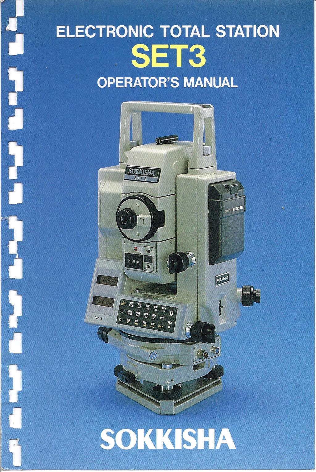
7 2. FEATURES Horizontal angle, zenith angle, slope distance, horizontal distance, height difference, N- and E-coordinates are displayed by key operation. Horizontal distance between two prism points and remote measurement of objects above and below a prism point are automatically calculated. A setting-out (stake-out) function for angles or distances is provided. Self-diagnostic function. If, for any reason, the SET3 is not functioning correctly during use, an error code is displayed. Angle resolution can.be set to l" (0.2mgon) or 5" (l mgon). The tilt angle of the vertical axis can be measured by the internal sensor and displayed. By referring to the display, the SET3 can be levelled. The zenith angle is automatically compensated by the tilt sensor and the compensated angle displayed. Horizontal circle can be set to zero in any direction. The SET3automatically switches off 30 minutes after the last operation to save battery power. An RS-232C data-output connector is standard. Two way communication with a field or office computer is available.
8 3. SPECIFICATIONS Distance measurement Range: (When using Sokkisha standard reflecting prisms) Average conditions: (Slight haze, visibility about 20 km, sunny periods, weak scintillation) l -prism 1,900 m 3-prisms 2,600 m Good conditions: (No haze, visibility about 40km, overcast, no scintillation) l -prism 2,200 m 3-prisms 3,000 m Standard deviation k(5mm -I-3ppm.D) Display: LCD 8-digit Four display windows, two on each face Maximum slope distance 9, m Minimum display: MEAS. 1 mm TRACK. lomm Measuring time: Mode Slope distance Horizontal distance / MEAS. 1 TRACK. 1 Coordinates Remote elevation distance between two points Atmospheric correction: Prism constant correction: Earth-curvature and refraction correction: Audio target aquisition: Signal source: Light intensity control: / 7 s + every 1 s 1 s + every 0.5 s 8 + every 5 S 8 S + every 1-99 ppm to +l99 ppm (I ppm per step) -99 mm to +59 mm (1 mm per step) Selectable ON/OFF Selectable ON/OFF Infrared LED Automatic
9 Angle measurement Telescope Length: Aperture: Magnification: Resolving power: I mage: Field of view: Minimum focus: Horizontal circle Type: Minimum display: Vertical circle Type: Minimum display: Accuracy Automatic compensator Type: Minimum display: Range of compensation: Display Range: 177 mm 45 mm, EDM: 50 mm 30 X 3" Erect 1 30' (26 m/l,000 m) 1.3m l ncremental l " (0.2 mgon) Incremental with 0 index l" (0.2 mgon) Standard deviation of mean of measurement taken in positions I and I1 (DIN 18723) 3" (0.9 mgon) 3" (0.9 mgon) Selectable ONIOFF Liquid 1" (0.2 mgon) + 3' Measuring mode Horizontal angle: Vertical angle: Measuring time: Right/Left/Repetition of angles Zenith O0 (Ogon) or Horizontal 0" (Ogon) or Horizontal 0 rt900 (0 gonk l00 gon) Less than 0.5s
10 Sensitivity of levels Plate level: Circular level: Optical plummet Image: Magnification: Minimum focus: Data input/output: Self-diagnostic function: Power saving cut off: Operating temperature: Power source: Working duration: Charging time: Instrument height: Size (without handle): Weight: Erect 3 X 0.1 m Asynchronous serial, RS-232C compatible Provided 30 minutes after operation -20 C to +50 C Ni-Cd battery, BDC18 (6V) About 600 measurement at 25OC, distance and angle measurement; 13 hours at 25"C, angle measurement only. (About 4,000 measurements, distance and angle measurement; 90 hours at 2S0C, angle measurement only, with optional battery BDCl2.) 12 to 15 hours, standard charger CDCI 1 ICDC1 l D (depending on input voltages) (1 hour, optional charger CDCI 2A, CDC13, CDC15) 236 mm 168(W)x177(D)x330(H) mm 7.6 kg (wlinternal battery)

11 4. STANDARD EQUIPMENT Fig. 4.1 SET3 main unit... 1 Internal battery. BDC Battery charger. CDCIIICDCIID... 1 Battery charging adaptor. EDCll... 1 Tubular compass. CP7 (accuracy: + 1')... 1 Lens cap... 1 Lens hood... 1 Vinyl cover... 1 Plumb bob... 1 Tool pouch... 1 Screwdriver... 1 Lens brush... 1 Adjusting pin... 2 Cleaning cloth... 1 Atmospheric correction chart... 1 Operator's manual... 1 Carrying case. SC
12 5. POWER SUPPLIES The SET3 can be operated with the following combinations: 12 to 15 hours * Standard set. (l00 to 120V AC) Optional accessories are not marked with an asterisk. (220 to 240V AC) l hour quick charger CDC12A (120V AC) 1 hour cigar lighter charger CDC13 (12V DC) 1 hour quick ; ; g ; ; ; AC power adaptor (100,120, 220,240V AC) External battery E%@ 15 hours charger CDC14A (120V AC) Fig. 5.1 Cable to cigar lighter EDC4 " '8 Cable to car External battery battery converter EDC5 EDC14 Use the SET3 only with the combinations shown here. Note: When using the SET3 with external power supplies, it is recommended that for the most accurate angle measurements, the BDC18 battery be left in place to balance the weight on the axes.
13 Battery charging precautions To charge the battery, use only the recommended charger. 1) Charge the battery at least once a month if it is not used for a long time. 2) Charge the battery at a temperature between 10 C and 40 C. 3) Before using EDC2 or CDCI 5, set the voltage selector to the proper voltage. 4) EDC14 has a breaker switch. Normally the red mark appears on the breaker. If not, set the red mark in place. 5) When using a car battery, make sure that the polarity is correct. 6) Make sure that the cigar lighter has 12V output and that the negative terminal is grounded. 7) When charging the battery, first connect it to the battery charger and then connect the charger to the power supply. Check that the battery charger light is on. If not switch power supply off and on again until the light comes on. 8) The battery charger may become warm while charging. This is normal. 9) Do not charge the battery for any longer than specified. 10) Store the battery in a place where the temperature is between 0 C and 40 C. 11) Battery operating life is shortened at extreme temperatures.
14 6. REFLECTING PRISMS AND ACCESSORIES All Sokkisha reflecting prisms and their accessories have standardized screws (518" X 11 thread) for easy compatibility. APS12P APSl lp Fig. 6.1 *All the equipment described above is optional. *I: See Prism constant correction. "2: Fluorescent paint finishing allows clearer sighting in adverse observing conditions
15 Precautions 1 ) Carefully face the reflecting prism towards the instrument; sight the target centre accurately. 2) To use the triple prism assembly AP31 or AP32 as a single prism (e.g. for short distances), mount the single prism APOI in the centre hole of the triple prism holder. 3) Check that "236" (the height of the SET3) is displayed in the window of the instrument height adaptor AP41. The height of the AP41 can be adjusted as Loosen the two fixing Turn the centre part counterclockwise to unlock Move it up or down until "236" appears in the Turn the centre part clockwise to re-lock Tighten the fixing screws. Fig. 6.2 Fig. 6.3 Note: SET3 instruments with a serial number less than have a height of 233 mm. 4) Use the plate level on the AP41 to adjust the tribrach circular level as in ) Check the optical plummet of the AP41 as in After all checks and adjustments have been completed, make sure that the AP41 optical plummet sights the same point as the optical plummet of the SET3.
16 7. DISPLAY SYMBOLS, H I' H, Horizontal angle right Horizontal angle left 4 Slope distance d Horizontal distance d l Height difference i ILL+ N-coordinate g+ E-coordinate -- I + Compensated angle -I, Tilt angle I Horizontal angle. H "' repetition t H 4Ibb S.0 Zenith angle V between two polnts e I Distance, angle or error code Fig. 7.1
17 8. KEY FUNCTIONS SET3 has three measurement modes. When it is switched on and the vertical circle is indexed by rotating the telescope, it is automatically in the theodolite mode. Fig. 8.1 Theodolite mode Angle measurement. SET3 accepts a, Basic mode m Prism sighting, data entry and recall. SET3 accepts all keys except a. EDM + Theodolite mode Angle and distance measurement. SET3 accepts or keys. m, m or B keys. m, m, 6/) or B keys.
18 Fig e Select theodolite mode. * Stop data entry halfway before m has been Stop measurement and transfer to basic mode. Set horizontal angle to zero. To confirm zero setting, press m. When using the "Measuring distance between 2 poinrs" function, set the starting point to the values of the last measured point. m * Change the sign of data before entry. Recall data from Enter "7". m Measure slope dis7ance. Enter "8". e Measure horizontal Enter Measure height difference. CIear entry. Select horizontal angle to left, right or by repetition (accumulation).
19 m 0 EDM power ON/OFF for locating Enter decimal point. e Measure setting out (stake-out) e Enter "4". e Measure N- and Enter "5". Measure remote elevation e Enter "6". 0 Measure horizontal distance between two prism points. Display vertical axis tilt angle ON/OFF m 0 Illuminate display and reticle of telescope for 30 seconds. Enter "0". Q Enter horizontal angle when setting horizontal circle to a certain value. 0 Enter "1". Enter setting out (stake-out) distance. Enter "2". 0 Enter setting out (stake-out) horizontal angle, Q Enter "3". e Enter coordinates of instrument station. Transfer entered data to memory. Confirm input of (setting horizontal angle to zero).
20 I"' z L" m TILT 0 m FEET m 0"i90" 9. INTERNAL SWITCHES Switches are located under internal switch cover r Fig. 9.1 I Switch I Function I 1 1 ON Angle resolution 5"/1 mgon * OFF Anoe resolution 1 "/0.2 rnaon ON Manually index vertical circle by V,, V, *OFF Automatically index vertical circle by transitting telescope l ON Vertical circle compensator off *OFF Vertical circle compensator on ON 'OFF l Display distance in feet Display distance in meters ON Distance corrected for earth-curvature and refraction * OFF Distance not corrected for earth-curvature and refraction ON Display vertical angle with 0' (Ogon) horizontal 190 i100goni *OFF Vertical anale display controlled by switch 1 ON Display vertical angle with O0 (Ogon) horizontal * OFF Displav zenith anale (The asterisk indicates the position of each switch at the time of shipping from factory.) Before changing switch settings, turn power switch OFF.
21 10. OPERATION 10.1 PREPARATION FOR ANGLE MEASUREMENT Battery, BDC18: Mounting and check 1 ) Confirm that the power is OFF. 2) Mount the battery BDC18 in the SET3. Hold the left standard when inserting the battery. Push it until a click is heard to indicate correct location. Confirm that the battery is fixed securely. Release button Guide To remove the battery, turn the power switch OFF and push down the release button of the battery. 3) Two short audio signals are heard when the power is switched ON. The display shown and indicate the instrument is in normal condition... I I second Fig. 10.2
22 If the battery voltage is too low, the display will appear as shown below. Set the power switch OFF and replace the battery with a charged one, or charge the battery. Battery voltage is too 10~. Fig Compensation of zenith angle 1 ) Remove the switch cover a. 2) To use zenith angle with compensation, set switch 5 to OFF with a screw driver. (The factory setting is OFF.) 3) Replace the cover. h (0 z "= 0.t 0 N Compensation select switch.m3 ON - Without compensation "Cmn OFF -With com~ensation This mark appears when the internal switch 5 is set to 0 F F. When this mark appears, the angle is M compensated automatically. n9-1 r~h n" Fig The internal tilt sensor has a range of +3' and a resolution of 1 ". Read the automatically compensated zenith angle when the display is steady. When the display is not steady due to vibration or strong wind, set switch 5 to ON to use the SET3 without compensation.
23 Centring the SET3 by adjusting tripod leg length 1 ) Make sure that: a. The tripod head is approximately level. b. The tripod shoes are firmly fixed in the ground. 2) Set the SET3 on the tripod head. Tighten the centring screw. 3) Focus on the surveying point: a. Turn the optical plummet to focus on the reticle. b. Turn the optical plummet focussing to focus on the surveying point. 4) Turn the levelling foot to centre the surveying point in the reticle. 5) Observe the off-centre direction of the bubble in the circular level (D. Shorten the leg nearest that direction, or extend the leg farthest from that direction. Generally, two legs must be adjusted to centre the bubble. 6) When centring of the circular level is completed, turn the levelling screws to centre the plate bubble. 7) Look through the optical plummet again. If the surveying point is off-centre, loosen the centring screw to centre the surveying point on the reticle. Tighten the centring screw. 8) Repeat 6), 7) if the plate level bubble is off-centre Focussing 1) Looking through the telescope, turn the eyepiece fully clockwise, then anticlockwise until just before the reticle image becomes blurred. In this way, frequent refocussing can be dispensed with, since your eye is focussed at infinity. 2) Loosen the and horizontal Bring the target into the field of view with the peep Tighten both clamps. 3) Turn the focussing and focus on the target. Sight the target with the and horizontal fine motion Focus on the target until there is no parallax between the target and the reticle.
24 Parallax: Relative displacement of target image in respect to the reticle when observer's head is moved slightly before the eyepiece. If sighting is carried out before parallax is eliminated, this will introduce errors in reading and will impair your observations ANGLE MEASUREMENT r Make sure that: a. The SET3 is set up correctly over the surveying point. b. Battery voltage is adequate Automatically indexing vertical circle 1) Turn the power ON. Make sure that the display appears as shown below. 400 gon Fig ) Loosen the vertical clamp a, and use the telescope plunging to rotate the telescope completely. (Indexing occurs when the objective lens crosses the horizontal plane in position V1.) When the vertical circle is indexed, an audio signal is given and the display appears as below. 400 gon *I... I In* ,-, 4-t S-, 8-8 L1,-l!-l,-l 8-1 $7,-l 6 7 #-l,l,-l t-l #-l Fig. 10.6
25 Angle measurement can now begin. Note: When the power switch is turned off for any reason, the vertical index is lost. When the power switch is turned back on, the vertical index must be redetermined Angle measurement Before this procedure, index the vertical circle. l) Select theodolite mode by pressing m. 2) Select the horizontal angle right or left with according to measuring method. l Display H #)... Horizontal angle H qfl... Horizontal angle left H I))... Horizontal angle repetition Fig When is pressed, the display changes alternately as shown in Fig ) Sight the first target A. 4) Press and m to set the horizontal angle display to O0 (0 gm). 360" 400 gon i Fig. 10.8
26 5) Use the horizontal and the vertical to sight the second target B. Zenith angle v] Horizontal angle 360' 400 gon IC l1 lr u ?.8358 V S?.r!B? C# nun^^ r] Fig The displayed horizontal angle is the angle between targets A and B Setting the horizontal circle to a required value i.e. reference target value 1) Entry of horizontal angle of a target. Press B to stop measurement. Enter as follows: 0 To clear the entry halfway, press 0 TO stop the entry halfway, press B. * The entered horizontal angle should be between 0 00'00" ( gon) and 1999'59'59" ( gon). When an input data value exceeds 360" (400gon), the value is displayed minus 360" (400gon). Example: '10" '10" gon -t gon entered displayed 2) Measurement Example: Sight the target A and make sure that the horizontal and vertical clamps are fully tightened. Press B 10 stop measurement.
27 Enter the required horizontal angle e.g '20". About I S - Fig Target A has now been set to 15 36'20" Repetition of angles Repetition of angles from -1,999 59'59" to 1,999 59'59" (-1, gon to 1, gon) is displayed by using m. 1 ) Press to select repetition of angle. H I,, Fig ) Sight target A, and press 0&) and m... Repetition of angle display 400 gon Fig
28 3) Use the horizontal and the horizontal fine motion to sight target B. 360' 400 gon Fig ) Use the lower and the lower fine motion to turn back to target A. Important: Do not turn the horizontal clamp or fine motion screw during this procedure. 360" 400 gon Fig ) Use the horizontal clamp and the horizontal fine motion screw to sight target B. 360' 400 gon Fig ) Repeat 4), 5) steps to measure repetition of angles. 7) To release the repetition of angle display, press m.
29 10.3 PREPARATION FOR DISTANCE MEASUREMENT Prism constant correction 1) Remove the prism constant switch cover (D with a coin. 2) Use the screwdriver to turn the X l0 mm index and X l mm index to match the reflecting prism constant correction value. Example: Apply a prism constant correction of -30 mm: -30 mm = -3 X l0 mm - 0 X 1 mm. Therefore, set the X l 0 index to C and the X l index to 0. Note: The sign (+/-) of the SWxl value corresponds to the sign of the SWx l 0 value. ~ ~ X I O l 2, Sian +l- corresoonds to SWX 10 3) Replace the cover. Fig Prism constant values of Sokkisha reflecting prisms. The prism constant of the AP series prisms is 30 mm (the same value as the previous Sokkisha prism) using the prism spacer APOlS (standard accessory). The constant can be changed to 40 mm by removing the prism spacer. PR03 APOIS+APOI APO l Fig When using reflecting prisms with constant values other than the above, a prism constant correction of -99 mm to 159 mm can be set in steps of 1 mm using the X 10 and X l indices.
30 Atmospheric correction The SET3 is designed so that the correction factor is 0 for a temperature of +l 5OC and an atmospheric pressure of 760 mmhg. The correction factor is obtained from the pressure and temperature as follows. 1) Measure the temperature and atmospheric pressure with a thermometer and a barometer. Pressure can be obtained from weather station sea level data by correcting for altitude. For altitude correction see To convert millibars to mmhg, multiply by Example: 959 millibars 0.75 X 959 = 719 mmhg 2) Read the correction factor from the atmospheric correction tables on pages 70 and 71. Example: Temperature +25"C Atmospheric pressure 750 mmhg Correction factor is tl 3 ppm. Temperature I PP- Fig ) Set the ppm to t13. 4) To obtain the atmospheric correction factor by computation. Example A: Using pressure in mmhg X P Atmospheric correction factor X = X t P: Atmospheric pressure in mmhg t: Temperature in centigrade
31 4) To obtain the atmospheric correction factor by computation X P Atmospheric correction factor X = X t P: Atmospheric pressure in mmhg t: Temperature in centigrade Example: P = 750 mmhg, t = +25OC To convert millibars to mmhg multiply by Example: 959 millibar 0.75~ mmHg 5) The corrected slope distance is calculated by the formula: D: Corrected slope distance d: 'The display of slope distance when ppm is set at 0 X: Correction factor in ppm Example: Slope distance 2, m X = +5 ppm
32 Earth-curvature and refraction correction 1) Remove the internal switch cover 0. 2) To correct horizontal distance and height difference for earthcurvature and refraction, set switch 3 to ON with a screwdriver. 3) Replace the cover. Earth-curvature and correction switch -m ON -Correction is applied. m m OFF-Correction is not applied. refraction Fig This correction is performed in the measurement of horizontal distance and height difference. The value displayed by the SET3 is computed by the following formula: When the switch is ON Horizontal distance after correction Height difference after correction l-k V'= Sxcos Z + - X S* xsin2 Z 2 R When the switch is OFF Horizontal distance H=SxsinZ Height difference V=SxcosZ S: Slope distance (value after atmospheric correction) Z: Zenith angle K: Atmospheric refraction constant (0.142) R: Radius of the earth (6.372 X 10⁶m)
33 Target 2 Average sea level t 1 Fig Example: Amount of correction at a zenith angle 70" I000 I500 H' - H (m) V' - V (m) Note that the horizontal distance is a distance measured at the height of the surveying point above the sea level. It is necessary to reduce this distance to the average sea level and to apply the local projection correction Prism sighting 1) Sight the centre of the reflecting prism with the telescope. 2) Set the return signal audio to P. 3) Set the power to ON and press m. turns the power supplied to the EDM unit ON or OFF. Usually the power of the EDM unit turns OFF automatically after 1 second of inactivity and the power source mark disappears. But when m is pressed, power is supplied to the EDM unit for about 2 minutes to permit prism sighting. a. When power is supplied to the distance measurement unit (EDM unit), the power source is displayed.
34 b. When the reflected light is received by the telescope, an audio signal is heard and the return signal lights UP. When the light intensity coming back from the prism is very high, the return signal lamp may light up, even for a slight mis-sighting. Make sure that the target centre is sighted correctly. 4) Switch off the audio target acquisition Mode selection 1) Select the mode to MEAS. for fine measurement, or TRACK. for tracking. - Fig measurement TRACK.: tracking measurement MEAS.: Measures in mm units at first after 7 seconds and then every 5 seconds. TRACK.: Measures in cm units at first after 7 seconds and then every 0.4 to 1 second.
35 10.4 DISTANCE MEASUREMENT -Make sure that: a. The SET3 is set up correctly over the surveying point. b. The prism constant switch, the earth-curvature refraction switch, and ppm switch are set correctly. c. Battery voltage is adequate. d. Indexing the vertical circle is complete Angle and distance measurement 1) Press H to stop angle measurement. Fig U 2) Press and sight the centre of the reflecting prism. (See ) 3) Press a to measure slope distance. The following display appears showing that the slope distance measurement is being performed. Display flashes Fig m 4) The slope distance and the zenith angle will be displayed after about 7 seconds. _I_+ s i r22d I i.60~) Zenith angle Fig Slope distance: m (fine measurement) Slope distance will continue to be measured every 5 seconds
36 9 When the following keys are pressed instead of a in step 3), the measurement corresponding to each key is performed. Key operation During measurement Measured value j4 Horizontal 33 ;88'5', distance I I C L II * Zenith angle - Height I] 3515'53, difference Fig ) Press B to stop measurement. * Horizontal and zenith angles are displayed in real time.
37 6) After stopping, you can recall the following observational data, which are stored in the instrument, by pressing the appropriate keys. Key operation Measured value 1 &'h 1 zenith angle 1 v/,/, ' angle 1 8 {722gr' 1 Zenith Horizontal angle 4 d l // y.55 Slope distance Horizontal angle Horizontal distance Height Fig Each distance value displayed is the result obtained in the latest measurement. 7) To use as a theodolite after distance measurement, press then p. H
38 Measurement of coordinates Vertical line 1 L: Horizontal distance \ Instrument station (X,, Y,) Fig \--Start point (0, 0) 1 ) The SET3 computes coordinates using the formulas: N (X)-coordinate = X. + L cos OH E (Y)-coordinate = Yo + L sin OH 2) The observation procedure is the same as Because the N component is positive for north and the E component is positive for east in plane rectangular coordinates, you should select the horizontal angle right and set the horizontal circle to zero on north. 31 For example: 0' *A Y/E Fig Point No. 0 A B Horizontal distance Horizontal angle - 20" 1 5'1 0" ( gon) 225" 32'50" ( gon) N-coordinate E-coordinate ,
39 4) Press to stop measurement. Measure coordinates as follows. a. Entry of instrument station To clear the entry halfway, press TO stop the entry halfway, press The range of coordinates is between -9, m (-9, ft) and 9, m (9, ft). The coordinates are retained in the memory of the SET3 for about 5 days even when the power switch is turned OFF. After that, the coordinates become (0, 0). Example: Entering the instrument station coordinates (610, 770) VUVV Stored coordinates are displayed. Enter the N-coordinate. ri n n n 1 --mmmm 6 :2?22 1 ;,gut 1. 1 Enter the E-coordinate. -I -I CI 0,-I,-I Fig b. Confirmation of instrument station coordinates Confirm the displayed To correct the stored coordinates, re-enter them.
40 c. Measurement of target point coordinates g23rgr.j Measurement During Measured measurement coordinates Fig stop Remote elevation measurement At certain surveying points e.g. power transmission lines or cables supporting bridges, etc., a reflecting prism cannot usually be positioned. In such cases the remote elevation measurement makes height differences easy to measure. h=hl +h2 h, = S (sin 6Jzl X cot OZ2 -COS 6Jzl) Fig ) Between the ground and the object a. Set up a reflecting prism under the object and measure the prism centre height from the ground with a tape Use an optical plummet to set the prism accurately. b. Enter the height, h, measured in step a., as a positive value, as setting-out data.
41 Example: The prism centre height from the ground is m n n n n l V!-l Cl U Enter the data Fig c. Sight the reflecting prism and press a. Press a after the distance measurement data is displayed. During measurement 1 ;g Measurement stop Measured value Fig The measured value is stored in the SET3. d. Press a, then a. During measurement About 1 {5,?3. l S.0 A Measured value Fig
42 When the SET3 is sighted on the prism, the height, h,, measured with a tape measure (the prism height from the ground) will be displayed. e. Sight the object. The object height from the ground, h, will be displayed in the lower display. Fig. '10.36 Measurement stop * The range of measurement is between vertical angles of -89" (-98gon) and 89" (98gon) Measurement of horizontal distance and height difference between two or more target points Horizontal distance L and height difference H between two or more points can be measured Fig To measure horizontal distances and height differences between: PI (the first starting target) and P, Pg or P4; and then: between P, (the second starting target) and P".
43 l) Set up the reflecting prisms on the target points P,, P,, P, P4,...,P". 2) Sight the prism P, and Press a after the distance measurement data is displayed. --B During measurement Measured value Fig The measured value is stored in the SET3. 3) Sight the reflecting prism P, and During measurement Horizontal distance and height difference between P, and PZ Fig ) To measure the horizontal distance and height difference between P, and Pg, P4, press after sighting each prism. 5) Change of the starting target point. Note: Only the last-measured point (i.e. Pq) can be used as the starting target in this procedure.
44 Press a. ' Horizontal angle of the new " " 8 { :,g;':( starting target point. -. _-.A r---ii Horizontal distance of the I,,,00,,3C,,-,-,,-,, I new starting target point. I.. I Fig * The displayed value is stored in the SET3. 6) To measure the horizontal distance and height difference between P, and P, press B after sighting the prism P, SETTING-OUT (STAKE-OUT) MEASUREMENT Horizontal angle setting-out (stake-out) measurement The SET3 displays the value of the horizontal angle to be set out minus the measured horizontal angle in the upper display, and the measured horizontal angle in the lower display. 1 ) Entry of horizontal angle value to be set out. a. Press m to stop measurement. Enter as follows: 0 To clear the entry halfway, press m. * To stop the entry halfway, press. B 8 The entered horizontal angle should be between 0 00'00" (0.0000gon) and 1999~59'59" ( gon). * When an input data value exceeds 360' (400 gon), the value is displayed minus 360 (400gon). Example: '10" '10" gon gon entered displayed e The data once entered is stored until the power switch is turned OFF and then becomes zero.
45 b. Entry of setting-out horizontal angle data. ~ressh to stop measurement. Example: Setting-out a horizontal angle of '00" Fig ) Measurement Displayed value = setting out value - measured horizontal angle The range of displayed values in the upper display is g:-tg'ngrr 1 Turn the alidade b Horizontal angle at the point Fig
46 Distance setting-out measurement 1) Setting out a distance. The SET3 displays the measured distance minus the distance to be set out 2) Entry of distance value to be set out. The distance must be entered for slope distance, horizontal distance or height difference measurements. Press B to stop measurement Enter as follows. a - I Enter data I - To clear the entry halfway, press m To stop the entry halfway, press B. The entered distance should be between m and m. The data once entered is stored until the power switch is turned OFF and then becomes 0. 3) Confirmation of setting out distance data. Confirm the displayed To correct the stored data, re-enter it 4) Measurement The following distance measurements can be performed with m. Key operation Slope distance setting-out Horizontal distance setting-out \- Height difterence setting-out Fig
47 Example Setting-out a hor~zontal d~stance of 90 5 m a. Entry of distance value to be set out. nnnn Enter the data. Stored data is displayed. About / s b. Measurement Fig During measurement Measured distance and horizontal angle Fig The measured horizontal distance is m longer than the setting-out distance (90.5 m).
48 11. SELF DIAGNOSIS If there is any fault in the measuring function, the error codes shown in the following table will be displayed. I Display I Meaning I Action Battery voltage is too low. Replace the battery with a charged one, or charge the battery. - I l-i l-c C 1lJI-l 1-1 t -1 C r f f *Error when measuring a horizontal angle. when measur- Ing a zenith angle. Compensator range error. Tilt angle exceeds -3'. Compensator range error. Tilt angle exceeds +3'. Incoming ref iected light decreased during measurement. Incoming reflection was disturbed. Incoming reflection is totally absent when the instrument is ready for distance measuring. Reset to the horizpntal angle 0" (0 gon). Index the vertical circle again. Level the SET3 again. Sight the reflecting prism again. Increase the number of the reflecting prisms for a long distance. Measure the distance again confirming the condition with the return signal lamp or sound.
49 Display Meaning Error when measuring the initial slope distance during either remote elevation or horizontal distance between two points measurement. During remote elevation measurement, the vertical angle is more than t8g0 (t98gon) or the measured distance is more than t9, m. The measured distance is more than rt 19, m (+ 19, ft). Act ion Sight the reflecting prism and perform slope distance measurement again. Press H to stop measuring. Press H to stop measuring. t- :l I t-l C C r y During horizontal distance between two points measurement, L' (horizontal di~t.~) is more than 1 O7 m. * If the SET3 is rotated faster than four revolutions per second, the error indication "E100" or "E101" is displayed. When the error indication "E" appears with any number other than the ones above, please contact our agent.
50 12. OPTIONAL ACCESSORIES 12.1 DIAGONAL EYEPIECE DE18 The diagonal eyepiece is convenient for steep observations and in places where space around the instrument is limited. Remove the by loosening the mounting ring, and screw in the diagonal eyepiece. Setting up the DE18 Fig ELECTRONIC FIELD BOOK SDR2 The SDR2 collects and stores slope distance, zenith and horizontal angle data from the SET3. Calculations can be performed on the data so that the measurements can be verified in the field. The stored data can be transmitted to a data processing system. Fig
51 SDR2 specifications Power source: "AA" (UM3) X 4 Memory type: CMOS RAM 16K or 32K ROM 16 K Keyboard: 33 keys Display: LCD Baud rate: 300, 600, 1200, 2400,4800 bps Operating temperature range: 0 to 50 C Weight: 450 g 12.3 INTERFACE lfla FOR THE HP-41CV Transfers data from the SET3 to the HP-41 CV computer. IFlA+ HP-41CV Fig I F1 A specifications lnput voltage: 6V, 12V Supplied from the SET2 lnput baud rate: 1200 bps Operating temperature range: 0 to 45 C Weight: 380 g Fig. 12.4
52 13. CHECKS AND ADJUSTMENTS The SET3 may be affected by sudden changes in weather conditions and excessive vibration. This can result in inaccurate surveying. Therefore, IT IS IMPORTANT TO CHECK AND ADJUST THE SET3 BEFORE AND DURING USE in the following order ANGLE MEASURING FUNCTION 13.1.l Plate level Circular level Index error of the tilt angle sensor Reticle Perpendicularity of the reticle to the horizontal axis Coincidence of the distance measuring axis with the reticle Optical plummet Plate level The glass tube of the plate level is sensitive to temperature change or shock. Be sure to check the plate before use. l) See Figs and 13.2 for relation between bubble movement and rotation of the levelling foot screws. Fig Fig ) Turn the upper part of the SET3 until the plate level is perpendicular to a line between levelling screws A and B. Then centre the bubble using the levelling screw C. Levelling screw Plate level A
53 3) Turn the upper part 90' (100gon) until the plate level is parallel to the line between levelling screws A and B. Then centre the bubble by turning levelling screws A and B by the same amount and in the opposite direction. A L0 Fig ) Turn the upper part 180 (200gon). Correct the bubble deviation, if any, by half the amount with leveliing screws A and B, as in 3) above. 5) Correct the remaining half deviation by turning the plate level adjusting with the adjusting pin. '1, A B Fig ) Repeat 2) to 5) above until the bubble remains centred for all the positions of the upper part.
54 Circular level When the plate level adjustment is complete, the circular should be checked. Note the direction off-centre of the bubble. Loosen the adjusting screw farthest from that direction and tighten the other adjusting screws to centre the bubble. 'LJ Fig Index error of the tilt angle sensor When the circular level adjustment is complete, the index error should be checked. 1) After indexing the vertical circle, tighten the vertical clamp a. 2) Press and QQ to set the horizontal circle to zero, then press m to display the tilt angle. Fig ) Loosen the horizontal clamp and turn the upper part through 180?r5' (200gon+0.1 gon). Fig
55 a+b, 4) Calculate - = ~ndex error c 2 Example: - 10" + 9" = -0.5" 2 5) If the index error is less than 5", no adjustment is necessary. For adjustment remove the sensor index adjustment Return to 0' horizontal angle position. Using a suitable flat screwdriver,adjust the internal screw until the upper display don =a - c. Turn the upper part through 180'. Adjust the internal screw until the upper display dlgo0 = b - C. Sensor index adjusting screw Fig Example: If a = -12", b = -6", index error c = - 12" + (-6") = 2
56 Reticle When the index error adjustment is complete, the position of the reticle should be checked. 1) Level the SET3. Select a clear target at a horizontal distance of 50 to l00 m. 50 to l OOm Fig ) After indexing the vertical circle, sight the target and take the horizontal angle reading in position Vl, e.g. a1 = 18"34'00" (a1 = gon) and the zenith angle reading, e.g. bl = 90 30'10" (bl = gon). Fig ) Next in position V2, sight the same target. Take the horizontal angle reading, e.g. a, = '10" (a, = gon) and the zenith angle reading, e.g. b, = '02" (b, = gon). 4) Calculate a, - al, b, + bl. a, - a1 = '10" '00" = '10" (a, - a1 = gon gon = gon) b, + bl = '02" '10" = '12" (b, + br = gon gon = gon)
57 5) When the reticle is in the normal position, your results should show that a, - al is within 20" of 180" (200 gon) and b, + bl is within 20" of 360" (400gon). If the difference of a, - a1 from 180' (200gon) or b, + bl from 360" (400gon) is 20" or greater after several checks, adjust as foiiows. 6) While still in position V2, use the horizontal and vertical fine motion screws to adjust the lower display, a, and the upper display, b,, to read: Example: If a[= 1 8"34'00" a, = 198O34'26" bl = 90 30'1 2" b, = 269"30f12" 7) Look through the telescope. The target is seen shifted from the vertical and horizontal reticle lines. 8) Remove the reticle adjustment Adjusting screws fb Fig
58 9) Adjust the reticle sideways with the adjusting screws unt~l the target is centrally w~thin the vert~cal I~nes, and then adjust ~t up or down with the screws until the target is centrally with~n the horizontal lines 10) Replace the cover Fig Fig The adjustment is very delicate. contact our agent. If it is difficult, please N.B. If amount of the reticle shift is too large, distance measuring may be affected. Do not adjust the reticle more than 20" (0.006gon).
59 Perpendicularity of the reticle to the horizontal axis 1) Select and sight a clear target on the upper part A of the vertical reticle line Fig ) Turn the telescope slowly upward with the vertical fine motion until the target slides to the lower part B, Fig If the target is still centrally within the vertical lines no adjustment is necessary. If necessary, adjust as follows. Fig Fig ) If the target at B is not on the reticle, slightly loosen the lower adjusting screw and either the left or right adjusting screw with the adjusting pin, then rotate the reticle plate until the reticle is perpendicular to the horizontal axis. Retighten the screws by the same amount. Fig ) Recheck the reticle position as in
60 Coincidence of the distance measuring axis with the reticle When the reticle has been checked, check the distance measuring axis relative to the reticle as follows. 1) Level the SET3. Set up the reflecting prism at a horizontal distance of 50 to 100 m. Fig ) Sight the reflecting prism centre and take the horizontal and zenith angle readings. (H and Z respectively) Fig ) Press m on the keyboard and make sure the return signal lights up. 4) Four more readings are necessary. Turn the horizontal or vertical fine motion screw slowly until the return signal lamp goes off. Then take readings. Readings H1, H,: when the telescope is directed to the left Readings Z, (right) of the sighted direction in 2) above. Zb: when the telescope is directed above (below) the sighted direction in 2) above. 5) Check the differences of HI (H,) against H, and Z, (Zb) against Z. When the four differences obtained are larger than 2.5' (0.046 gon), the coincidence is normal. If the differences obtained are less than 2.5' (0.046gon1, please contact our agent.
61 Optical plummet 1 ) Level the SET3. Centre a surveying point in the reticle of the optical plummet. Loosen the horizontal clamp and turn the upper part through 180' (200gon). If the surveying point is still centred, no adjustment is necessary. 2) If the surveying point is off-centre, correct half the deviation with the four adjusting screws, and correct the remaining half with the levelling screws.. Fig ) Repeat the adjustment if necessary.
62 13.2 DISTANCE MEASURING FUNCTION Check flow chart Power switch ON l r-leesesas'.l.. l Yes NO I:_.,..; displayed? ( : Power swttch OFF Sight reflecting prism correctly and press Replace or charge I Return s~gnalamp ON? Cover object~ve lens I check c;n'tact of I Return sigml lamp out? <** Replace or charge the batterv battery term~nals L Removercover 1 Select MEAS. and Power switch ON Audio tone heard? l Yes NO - dlsp1ayed7 ssssssa, Yes Contact our agent Fig
63 Additive distance constant The additive distance constant of the SET3 is adjusted to 0 before delivery. However, the additive constant can change with time and so should be determined periodically and then used to correct distances measured. 1) Determining the additive distance constant. The most reliable method of determining the additive distance constant is to test the SET3 on an established base line with a maximum range of approximately 1,000 m, and with 6 to 8 intermediate stations spaced at multiples of the instrument unit length, which is 10 m. Measurements should be taken in all combinations of the 6 to 8 stations. If an additive distance constant of greater than 5 mm is found please contact our agent. 2) Confirmation of the additive distance constant K if a base line is not available. a. Select points A and B on flat ground about 100 m apart, and C in the middle. b. Set up the SET3 at A, and measure the distance AB. Note: Be sure prism height is the same as the height of the SET3 objective lens centre. If ground is not level, use an automatic level to set correct instrument heights of all points. About loom A Fig B
64 c. Shift the SET3 to C, and measure the distance CA and CB. Fig d. Compute the additive distance error K using the formula: K=S-(CA+CB) --- AB, CA, CB: Average of ten measurements. e. Obtain K value three times. If all K are greater than 5 mm, contact our agent.
65 14. FOR ANGLE MEASUREMENT OF THE HIGHEST ACCURACY 14.1 LEVELLING BY REFERRING TO THE DISPLAY For the most accurate measurement of horizontal angles, particularly for steep observations, the SET3 should be levelled using the tilt angle display. The index error of the tilt angle can be eliminated by taking readings on O0 and 180'. 1) Level with the plate 2) Tighten the vertical with the telescope approximately horizontal. 3) Loosen the horizontal and turn the upper part of the SET3 until the plate level is parallel to a line between levelling screws A and B. Then press and to set the horizontal angle to O0 (Ogon) Fig Fig ) Press to display the tilt angle. Fig. 14.3
66 5) Wait for 3 to 4 seconds until the tilt angle reading is steady. Then press m and a. Fig ) Turn the upper part of the SET3 through 180' (200gon). Fig ) Wait for 3 to 4 seconds until the tilt angle reading is steady. Then press and a. n;1 n'n a" LlUVU J I. -'- l Fig ) Referr~ng to the tilt angle reading, level the SET3 using levelling screws A or B until the value in the display IS OOf l". Fig. 14.7
67 9) Turn the upper part of the SET3 through 90' (100gon). gnn 73n 1 " " 1 Fig ) Wait for 3 to 4 seconds until the tilt angle reading is steady. Then referring to the tilt angle reading, level the SET3 using the levelling screw C until the value in the display is OO+l". Fig ) Press to release the tilt angle display Fig The vertical axis error is now minimized.
68 14.2 MANUALLY INDEXING VERTICAL CIRCLE BY v1, v2 Like every theodolite, the SET3 will have a verticai index error. A vertical index error can be removed as follows. 1 ) Turn the power OFF, remove the internal switch cover and set switch 6 to ON. (When switch 6 is ON, the automatic indexing of the vertical circle by transitting the telescope is inactive.) 2) After levelling the SET3, turn the power ON and make sure that the display appears as shown below. 360' 400 gon j 1, ,-l,-l Cl CI *-I rrt-t n'n n" I 1 n n e-1 rt,-l I Fig ) In position Vl, accurately sight a clear target at a horizontal distance of about 30 m. 4) Press m and m. Fig " 400 gon Fig
69 5) Next in position V2, accurately sight the same target. Fig ) Press and a. When the vertical circle is indexed, the display appears as below. 360" 400 gon Zenith angle Horizontal angle Fig If the power sw~tch has been turned OFF, the vertical circle must be ~ndexed again. When moving the SET3 after measurement, turn the power OFF.
70 15. FOR DISTANCE MEASUREMENT OF THE HIGHEST ACCURACY 15.1 ACCURACY OF MEASUREMENT OF ATMOSPHERIC CONDITIONS The relation between measured distance and the velocity of light is given by T: The period between light emission and reception. C: The velocity of light in the air. C,: The velocity of light in a vacuum. n: Refractive index of the air. - The measured distance is affected by variation in the refractive index dd- dn. dn (or dd + D. dn) D n Therefore, the accuracy of measurement of the refractive index must be the same as that of the measured distance. To calculate refractive index to an accuracy of 2 ppm, temperature must be measured to within 1 C and pressure to within 5 mmhg TO OBTAIN THE ATMOSPHERIC PRESSURE To obtain the average refractive index of the air throughout the measured light path, you should use the average atmospheric pressure. In flat terrain there is little variation in the atmospheric pressure. In mountains, the following calculation should be used.
71 Example: Fig By the Laplace formula Zn - Z, = 18,400 ( &-?S! Log (P,/p,) t: Temperature ("C) Z: Height above sea level (m) P: Pressure (mmhg) P, = 760 mmhg Z, = 330 m Z2 = 650 m to = 20 C t, = 20 C t2 = 18 C 330 {Log ,400(1 t ~ 20) P, = 10 1; 731 Average pressure: mmhg
72 16. PRECAUTIONS AND MAINTENANCE 16.1 PRECAUTIONS 1) When the SET3 is not used for a long time, check it at least once every three months. 2) Handle the SET3 with care. Avoid heavy shocks or vibration. 3) If any trouble is found on the rotatable portion, screws or optical parts (e.g. lens), contact our agent. 4) When removing the SET3 from the carrying case, never pull it out by force. The empty carrying case should then be closed to exc!ude dust. 5) Never place the SET3 directly on the ground. 6) Never carry the SET3 on the tripod to another site. 7) Protect the SET3 with an umbrella against direct sunlight, rain and humidity. 8) When the operator leaves the SET3, the vinyl cover should be placed on the instrument. 9) Do not aim the telescope at the sun 10) Always switch the power off before removing the internal battery. 11) Always remove the battery from the SET3 when returning it to the case. 12) Do not wipe the or the carrying case with an organic solvent. 13) When the SET3 is placed in the carrying case, follow the layout plan. 14) Make sure that the SET3 and the protective lining of the carrying case are dry before closing the case. The case is hermetically sealed and if moisture is trapped inside, damage to the instrument could occur.
73 16.2 MAINTENANCE 1) Wipe off moisture completely if the instrument gets wet during survey work. 2) Always clean the instrument before returning it to the case. brush first, to remove minute particles. Then, after providing a little condensation by breathing on the lens, 3) Store the SET3 in a dry room where the temperature remains fairly constant. 4) If the battery is discharged excessively, its life may be shortened. Store it in a charged state. 5) Check the tripod for loose fit and loose screws.

74 17. ATMOSPHERIC CORRECTION CHARTS (Metric) Pressure (rnrnhg) The chart shows the correction every two ppm, while the atmos- pheric correction can be applied to the SET3 for every ppm

75 (English) Pressure (inchhg) The chart shows the correction every two ppm, while the atmospheric correction can be applied to the SET3 for every ppm. The specifications and general appearance of the instrument may be altered at any time and may differ from those appearing in catalogues and the operator's manual.
SET5W WATERPROOF TOTAL STATION
 SURVEYING INSTRUMENTS SOKKIA SET5W WATERPROOF TOTAL STATION Water, water everywhere... but not a drop of worry. The waterproof SET5W is ruggedly built to withstand harsh operating conditions. Being fully
3--Rv.ei. value ANGLE MEASUREMENT...' CONTENTS
 CONTENTS 3--Rv.ei 1. PARTS OF THE INSTRUMENT................... 1 2. FEATURES... 4 3. SPECiFiCATIONS.............. 5 4. STANDARD EQUIPMENT....................... 8 5. POWER SUPPLIES... 9 6. REFLECTING
Cleveland State University
 CVE 212 - Surveying Lab #1 MEASURING ANGLES & DISTANCES WITH A TOTAL STATION EQUIPMENT EDMI and Tripod Single prism mounted on a prism pole Field book Pencil 2 Walkie Talkies INTRODUCTION Recent developments
GT-510/510L series Instruction Manual
 GT-510/510L series Instruction Manual NO.3.20110322 Contents 1 INSTRUMENT FEATURES... - 1 2 QUICK GUIDE... - 2 2.1 INSTRUMENT PACKING...- 2 2.2 NAME OF INSTRUMENT PARTS...- 3 2.3 UNPACK AND STORAGE...-
Digital Land Surveying And Mapping(DLS&M) Dr. Jayanta Kumar Ghosh Department of Civil Engineering Indian Institute of Technology, Roorkee
 Dr. Jayanta Kumar Ghosh Department of Civil Engineering Indian Institute of Technology, Roorkee") Digital Land Surveying And Mapping(DLS&M) Dr. Jayanta Kumar Ghosh Department of Civil Engineering Indian Institute of Technology, Roorkee Lecture - 17 Total Station Introduction Welcome students, this
Digital Land Surveying And Mapping(DLS&M) Dr. Jayanta Kumar Ghosh Department of Civil Engineering Indian Institute of Technology, Roorkee Lecture - 17 Total Station Introduction Welcome students, this
取扱説明書 /INSTRUCTION MANUAL 自動レベル /AUTOMATIC LEVEL AT-B2/B3/B4 FC10386-A012-02
 取扱説明書 /INSTRUCTION MANUAL 自動レベル /AUTOMATIC LEVEL AT-B2/B3/B4 FC10386-A012-02 SURVEYING INSTRUMENTS INSTRUCTION MANUAL AUTOMATIC LEVEL AT-B2/B3/B4 Thank you for selecting the AT-B2/B3/B4. Please read this
Fig. 1. instrument is in the case
 1. Applications The NETH503 series Electronic Theodolite has an optical incremental grading system which features digital angle measurements. It can achieve measurement, calculating, display and memory
Automatic Level NP-732
 INSTRUCTIONS FOR USE Automatic Level NP-732 Contents Before use 2 1.Nomenclature. 3 2.Operation....4 2-1 Preparing before surveying...4 2-2 Surveying method..........5 2-2-1 Measuring altitude difference...5
WATTS MICROPTIC ALIDADE OPERATING INSTRUCTIONS 20-7
 WATTS MICROPTIC ALIDADE 20-7 OPERATING INSTRUCTIONS WATTS Operating Instructions for the WATTS MICROPTIC ALIDADE SA100 SA101 RANK PRECISION INDUSTRIES METROLOGY DIVISION Survey Equipment Sales Langston
INTRODUCTION TO ENGINEERING SURVEYING (CE 1305)
") INTRODUCTION TO ENGINEERING SURVEYING (CE 1305) Linear Measurements Sr Dr. Tan Liat Choon Email: tanliatchoon@gmail.com Mobile: 016-4975551 1 EDM, TOTAL STATION, PRISM AND POLE 2 ELECTROMAGNETIC DISTANCE
INTRODUCTION TO ENGINEERING SURVEYING (CE 1305) Linear Measurements Sr Dr. Tan Liat Choon Email: tanliatchoon@gmail.com Mobile: 016-4975551 1 EDM, TOTAL STATION, PRISM AND POLE 2 ELECTROMAGNETIC DISTANCE
SET4B; Electronic Total Station
 SET4B; Electronic Total Station CONTENTS 1. PRECAUTIONS................................ 1 2. PARTS OF THE INSTRUMENT................... 2 3. FEATURES... 4 4. KEY FUNCTIONS..............................
DWT-10 Instruction Manual
 DWT-10 Instruction Manual For Customer Service Call (781) 848-7702 or Fax (781) 848-8022 Congratulations on your choice of this David White Electronic Digital Transit. We suggest that you read this instruction
SOKKIA C0,LTD. 1-1, TOMIGAYA 1-CHOME, SHIBUYA IKYO, 151 JAPAN PHONE 'U TFLEX SURSOK J2851
 SURVEYING INS Electronic heodolite SOKKIA C0,LTD. 1-1, TOMIGAYA 1-CHOME, SHIBUYA IKYO, 151 JAPAN PHONE 03-3405-5211 'U. 03-3465-5203 TFLEX SURSOK J2851 OPERATOR'S MANUAL MEMO CONTENTS 1. PRECAUTIONS 2.
CIV : THEODOLITE ADJUSTMENT
 Unit CIV2202: Surveying 10.1 CIV2202.10: THEODOLITE ADJUSTMENT Table of Contents PREVIEW...2 Introduction...2 Objectives...2 Readings...2 REGULAR CHECKS...2 Tripod...2 Footscrews...2 Tribrach head...3
~.LIETZ ~. LI ETZ INSTRUCTION MANUAL DOUBLE CENTER THEODOLITE TM-20C THE LIETZ COMPANY E. Del Arno Blvd. Carson, Ca (213)
") ~.LIETZ DOUBLE CENTER THEODOLITE TM-20C INSTRUCTION MANUAL f~, ~. LI ETZ THE LIETZ COMPANY 1645 E. Del Arno Blvd. Carson, Ca. 90746. (213)537-0410 n INSTRUMENT NOMENCLATURE cr, il (~ iíl i) Ii: in CD CD
~.LIETZ DOUBLE CENTER THEODOLITE TM-20C INSTRUCTION MANUAL f~, ~. LI ETZ THE LIETZ COMPANY 1645 E. Del Arno Blvd. Carson, Ca. 90746. (213)537-0410 n INSTRUMENT NOMENCLATURE cr, il (~ iíl i) Ii: in CD CD
Carlson CR Robotic/Reflectorless Total Station
 0 West Second Street Suite 00 Maysville, KY 4056 www.carlsonsw.com Phone: 606-564-508 Fax: 606-564-64 Type starts around here Carlson CR Robotic/Reflectorless Total Station Calibration Overview Congratulations
SURVEYING INSTRUMENTS DT7C DT20C. Electronic Digital Theodolite OPERATOR'S MANUAL
 SURVEYING INSTRUMENTS DT7C DT20C Electronic Digital Theodolite OPERATOR'S MANUAL This is the mark of the Japan Surveying Instruments Manufacturers Association. SURVEYING INSTRUMENTS DT7C DT20C Electronic
Owner's Manual. for AUTOMATIC LEVEL. NBL Series. FOR CUSTOMER SERVICE, PARTS & REPAIR, CALL Toll Free:
 Owner's Manual for AUTOMATIC LEVEL NBL Series FOR CUSTOMER SERVICE, PARTS & REPAIR, CALL Toll Free: 1-888-247-1960 1 1. CONTENTS 2. Nomenclature page 3 3. Care and Maintenance page 4 4. Using your Instrument
Owner's Manual NSL100B BUILDERS LEVEL NSL500B TRANSIT LEVEL
 Owner's Manual NSL100B BUILDERS LEVEL NSL500B TRANSIT LEVEL 1 1. CONTENTS 2. Nomenclature page 3 3. Care and Maintenance page 4 4. Using your Instrument 4.1 Setting up your Instrument page 5 4.2 Stadia
Quick Start Guide. The ieq45 GoTo German Equatorial Mount # 8000C
 Quick Start Guide The ieq45 GoTo German Equatorial Mount # 8000C PACKAGE CONTENTS Telescope Mount (with built-in GPS) 3.5 Vixen type dovetail saddle (installed on the mount) 8 Losmandy-D type dovetail
Directions for use
 Directions for use 40070 40080 60050 70060 70076 80060 90060 900114 Fig. 1 Fig. 1A Fig. 2 Fig. 3 Fig. 4 Fig. 5 Fig. 6 Fig. 7 english ENGLISH DIRECTIONS FOR USE 1 Tripod Leg 2 Tripod Leg Adjusting Screw
22X Builder s Transit Level Model No Instruction Manual
 2595H 7/29/09 10:15 AM Page 1 22X Builder s Transit Level Model No. 40-6910 Instruction Manual Congratulations on your choice of this 22X Builder s Transit Level. We suggest you read this instruction manual
DT220 DT520 DT520S DT520A DT520AS DT620 DT620S
 SURVEYING INSTRUMENTS DT220 DT520 DT520S DT520A DT520AS DT620 DT620S Electronic Digital Theodolite OPERATOR'S MANUAL This is the mark of the Japan Surveying Instruments Manufacturers Association. SURVEYING
FOCUS 30/FOCUS 35 Field Calibration with Survey Pro Field Software
 GeoInstruments Application Note June 25th, 2015 FOCUS 30/FOCUS 35 Field Calibration with Survey Pro Field Software Summary: This support note outlines the procedure which should be followed to calibrate
Automatic Level Maintenance Manual SAL-XX W/ AIR DAMPENED COMPENSATOR
 Automatic Level Maintenance Manual SAL-XX W/ AIR DAMPENED COMPENSATOR CST/Berger 2001 SAL 20/24/28/32 PAGE 1 REV. C 071803 Automatic Level Maintenance Manual User Calibration and Testing... 3 Circular
22X Builder s Level Model No Instruction Manual
 2594H 7/29/09 10:12 AM Page 1 22X Builder s Level Model No. 40-6900 Instruction Manual Congratulations on your choice of this 22X Builder s Level. We suggest you read this instruction manual thoroughly
Leveling. 3.1 Definitions
 Leveling 3.1 Definitions Leveling is the procedure used to determine differences in elevation between points that are remote from each other. Elevation is a vertical distance above or below a reference
RECON. How to Setup the Telescope to Observe. This guide will show you how to setup your telescope for observing. Written By: Brittany McCrigler
 RECON How to Setup the Telescope to Observe This guide will show you how to setup your telescope for observing. Written By: Brittany McCrigler 2017 recon.dozuki.com Page 1 of 30 INTRODUCTION This guide
C A S S I N I TRACKER
 C A S S I N I TRACKER ASTRONOMICAL REFLECTOR T ELESCOPE SERIES #C-80080TR #C-1100102TR #C-1000120TR #C-1000120TREF #C-900135TR COSMO BRANDS INC. WWW.COSMOSOPTICS.COM 2 CASSINI REFLECTING TELESCOPE OPERATING
CASSINI CQR-800 OPERATING INSTRUCTIONS INTRODUCTION
 HQR-800 CASSINI CQR-800 OPERATING INSTRUCTIONS INTRODUCTION CONGRATULATIONS ON YOUR PURCHASE OF THE CASSINI CQR-800 TELESCOPE. THIS TELESCOPE HAS BEEN PRODUCED TO PRECISE SPECIFICATIONS. PRIOR TO USING
Total station LEICA TPS
 Total station LEICA TPS405 200 The perfect solution for all sites Rugged, adaptable total station with accurate angle measurements, dual-axis compensator, powerful EDM, data output in any format, and application
Surveying Instruments. B Series B20 B30 B40. Automatic Levels
 Surveying Instruments B Series B20 B30 B40 Automatic Levels World-Proven Precision and Durability B20 Automatic Level B30 Automatic Level B40 Automatic Level 28x 1.5mm Accuracy 32x 0.7mm Accuracy 24x 2.0mm
H050 E 97.1.DF.2. Automatic Levels AS-2 / AS-2C
 H050 E 97.1.DF.2 Automatic Levels AS-2 / AS-2C ikoninstruction Manual Thank you for purchasing the Nikon automatic levels AS-2/AS-2C. The AS-2/AS-2C is designed for high precision surveys in civil engineering
10.3 Vertical reticle
 Circular vial adj. screw Circular vial Tighten the screws equally after the above adjustment. Circular vial adj. screw 10.3 Vertical reticle [Checks] 1 Set the instrument up the tripod and carefully level
THE LOSMANDY G-11 MOUNT
 Checking the parts THE LOSMANDY G-11 MOUNT Depending on which accessories you ordered, your G-11 mount was shipped in four or more boxes. The contents of each box are as follows: Equatorial Mount Adjustable
C A S S I N I. MODEL : C EQ3 900mm X 135mm COSMO BRANDS INC.
 C A S S I N I MODEL : C-900135EQ3 900mm X 135mm COSMO BRANDS INC. WWW.COSMOSOPTICS.COM 2 C A S S I N I C-900135EQ3 TELESCOPE OPERATING INSTRUCTIONS INTRODUCTION CONGRATULATIONS ON YOUR PURCHASE OF THE
Polar Alignment of LX200R and Ultra Wedge For The Southern Hemisphere by Chris James
 Return To How To Menu Polar Alignment of LX200R and Ultra Wedge For The Southern Hemisphere by Chris James Overview This document goes thru the process required to Polar Align the LX200R using a Ultra
Appendix 2: Disassembling and Assembling the Telescopes and the Celestron Equatorial Mounts
 Appendix 2: Disassembling and Assembling the Telescopes and the Celestron Equatorial Mounts Disassembling (classroom) 1. The mount must be locked with the telescope situated horizontally. Note the telescope
CBRD30CP3 & BOWRD30CP INSTRUCTION MANUAL
 CBRD30CP3 & BOWRD30CP INSTRUCTION MANUAL PROLOGUE Your BSA Illuminated sight is for use on both compound and standard bows. Each version of the BSA illuminated sight has a specific reticle to help maintain
5-25x56 PMII PSR Illuminated with Double Turn
 Page 1 of 20 5-25x56 PMII PSR Illuminated with Double Turn Page 3 of 20 1. Scope description... 5 1.1 Introduction... 5 1.2 Safety instructions... 5 2. Technical data... 6 2.1 General data... 6 2.2 Dimensions...
Bright Advance Corporation
 USER INSTRUCTIONS TABLE OF CONTENTS INSTRUCTIONS FOR USE2 PREPARING TO USE THE SCALE2 DISPLAYS3 KEYBOARD FUNCTION4 OPERATION7 COUNTING14 DIFFERENT KEYBOARD TYPES21 INTERFACE31 POWER SOURCES40 1 INSTRUCTIONS
HS515G-M. PARALOW Circle Dot Sight. User's Manual. Holosun Technologies Inc. Phone: (909) Fax: (909)
 Fax: (909)") HS515G-M PARALOW Circle Dot Sight User's Manual Multi Reticle Holosun Technologies Inc. Phone: (909) 594-2888 Fax: (909) 598-4888 E-mail: info@holosun.com COLOR www.holosun.com PARALOW HS515G-M PARALOW
HS515G-M PARALOW Circle Dot Sight User's Manual Multi Reticle Holosun Technologies Inc. Phone: (909) 594-2888 Fax: (909) 598-4888 E-mail: info@holosun.com COLOR www.holosun.com PARALOW HS515G-M PARALOW
LEAPERS, INC. RED/GREEN DOTS
 LEAPERS, INC. 1 RED/GREEN DOTS range estimating scopes UTG reticle intensified scopes TOTAL SOLUTION TO YOUR NEEDS -COMMITMENT TO BEST QUALITY, BEST VALUE AND BEST SERVICEwww.LEAPERS.com 32700 Capitol
Welcome to purchase and use our products and thank you for your confidence in our company s products!
 PREFACE Dear users: Welcome to purchase and use our products and thank you for your confidence in our company s products! It has been our target to innovate the international-level advanced surveying instrument
ASTRO-PHYSICS, INC. POLAR ALIGNMENT TELESCOPE (PASILL2)
") OBJECTIVE LENS ASTRO-PHYSICS, INC. POLAR ALIGNMENT TELESCOPE (PASILL2) This model shipped from January 2001 through July 2002. It fits all 400, 600, 600E, 800, 900 and 1200 models (except the original
OBJECTIVE LENS ASTRO-PHYSICS, INC. POLAR ALIGNMENT TELESCOPE (PASILL2) This model shipped from January 2001 through July 2002. It fits all 400, 600, 600E, 800, 900 and 1200 models (except the original
SURVEYING INSTRUMENTS LDT520 LDT520S. Laser Digital Theodolite. Class 3R Laser Product OPERATOR'S MANUAL
 SURVEYING INSTRUMENTS LDT520 LDT520S Laser Digital Theodolite Class 3R Laser Product OPERATOR'S MANUAL Li-ion S Li-ion :This is the mark of the Japan Surveying Instruments Manufacturers Association. SURVEYING
Instruction Manual. Model #: (Reflector) Lit #: / 06-07
 Lit #: / 06-07") Instruction Manual Model #: 49114500 (Reflector) Model #: 49060700 () Model #: 49070800 () Lit #: 93-0468 / 06-07 PARTS DIAGRAM C E D B A F G H I J NOTE: Actual product may have improvements that are not
Instruction Manual Model #: 49114500 (Reflector) Model #: 49060700 () Model #: 49070800 () Lit #: 93-0468 / 06-07 PARTS DIAGRAM C E D B A F G H I J NOTE: Actual product may have improvements that are not
MODE button MAX/MIN button CHANNEL button / C/ F / RCC button SNOOZE / LIGHT button Battery compartment A/C in-jack 3. 4.
 KL4912 Desktop weather station Instruction Manual Introduction This weather station comes with backlight, indoor and outdoor temperature & humidity display, and alarm clock with calendar. Fig. 1 Front
5-25x56 PMII PSR With Double Turn
 Page 1 of 20 5-25x56 PMII PSR 5-25x56 PMII PSR With Double Turn Page 3 of 20 1. Scope description... 5 1.1 Introduction... 5 1.2 Safety instructions... 5 2. Technical data... 6 2.1 General data... 6 2.2
Optics. Measuring the line spectra of inert gases and metal vapors using a prism spectrometer. LD Physics Leaflets P
 Optics Spectrometer Prism spectrometer LD Physics Leaflets P5.7.1.1 Measuring the line spectra of inert gases and metal vapors using a prism spectrometer Objects of the experiment Adjusting the prism spectrometer.
WS-9018U Wireless Weather Station. Instruction Manual
 WS-9018U Wireless Weather Station Instruction Manual Contents Page 1. Functions of the Weather Station....3 2. Safety notes...3 3. Product features....4 4. Getting started....4 5. Quick Set Up...5 6. Setting
SCHIEBER TELESCOPES. Unique, High-Quality Telescopes
 SCHIEBER TELESCOPES Unique, High-Quality Telescopes 3.5 Refractor Astrophotography Bundle - Strike 90 PLUS Telescope Assembly Instructions and Digital Eyepiece Camera Instructions. (1) telescope assembly
PoleMaster User Manual (Northern Hemisphere)
") PoleMaster User Manual (Northern Hemisphere) 1. Hardware Installation 1.1 Attach the PoleMaster camera unit to the quick install plate using the three bolts supplied. In the case of the AZ EQ5-GT and Mesu
PoleMaster User Manual (Northern Hemisphere) 1. Hardware Installation 1.1 Attach the PoleMaster camera unit to the quick install plate using the three bolts supplied. In the case of the AZ EQ5-GT and Mesu
MC ILLUMINATED USER MANUAL
 1. MC-10-80 ILLUMINATED USER MANUAL Ringsights The MC-10-80 Illuminated offers the lowest profile for the FN PS90. It is a dual sourced sight with black ring for day and backup electronic illumination
PLI Support Guide: Robotic Total Station Field Calibration
 PLI Support Guide: Robotic Total Station Field Calibration Summary: This manual will instruct you on how to properly calibrate your Trimble Robotic Total Station using Trimble Access. Your instrument must
National Optical & Scientific Instrument Inc Tri-County Parkway Schertz, Texas Phone (210) Fax (210)
 Fax (210)") National Optical & Scientific Instrument Inc. 6508 Tri-County Parkway Schertz, Texas 78154 Phone (210) 590-9010 Fax (210) 590-1104 INSTRUCTIONS FOR SHOP MICROSCOPES MODEL NUMBERS 186 187 188 189 National
National Optical & Scientific Instrument Inc. 6508 Tri-County Parkway Schertz, Texas 78154 Phone (210) 590-9010 Fax (210) 590-1104 INSTRUCTIONS FOR SHOP MICROSCOPES MODEL NUMBERS 186 187 188 189 National
Platinum Series. 6-30x56 Front Focal Plane Scope. with Patented ACSS.308/.223 HUD DMR Reticle. Advanced Combined Sighting System
 6-30x56 Front Focal Plane Scope with Patented ACSS.308/.223 HUD DMR Reticle Advanced Combined Sighting System combining Bullet Drop Compensation, Range Estimation, Wind and Leads in one easy-to-use system
'-. MICROMEr II. The MICROMET8 II is shipped assembled except for the Filar Eyepiece, Micrometer Stage, and Standard Vise.
 MICROMEr II '-. UNPACKING: Carefully unpack and check contents. If any components are missing or damaged, save the packing list and material, and advise the carrier and Buehler Ltd. of the discrepancy.
ASTRO-PHYSICS, INC. POLAR ALIGNMENT TELESCOPE
 Polar Alignment Telescope ASTRO-PHYSICS, INC. POLAR ALIGNMENT TELESCOPE This polar axis telescope will help you align your mount with the Celestial Poles. When your mount is properly aligned, your telescope's
PULSE TOTAL STATION GPT-3000(L)N SERIES
N SERIES") GPT-3000(L)N SERIES PULSE TOTAL STATION Best Performance Non-prism measurement Features Visible Laser Pointer GPT-3000(L)N Series uses both an invisible Pulse Laser Diode for distance measurement and a
GPT-3000(L)N SERIES PULSE TOTAL STATION Best Performance Non-prism measurement Features Visible Laser Pointer GPT-3000(L)N Series uses both an invisible Pulse Laser Diode for distance measurement and a
Kalinka Optics Warehouse User Manual Kobra AK Side Mount Red Dot Sight Manual
 Kalinka Optics Warehouse User Manual www.kalinkaoptics.com Kobra AK Side Mount Red Dot Sight Manual CONTENTS 1. Introduction... 4 2. Purpose... 4 3. Specifications... 4 4. Components and Equipment Provided...
Acceleration/Velocity/Displacement VIBRATION METER
 Acceleration/Velocity/Displacement VIBRATION METER Model : VB-8220 Your purchase of this VIBRATION METER marks a step forward for you into the field of precision measurement. Although this METER is a complex
CASSINI CQR-120 OPERATING INSTRUCTIONS
 CASSINI CQR-120 OPERATING INSTRUCTIONS INTRODUCTION CONGRATULATIONS ON YOUR PURCHASE OF THE CASSINI CQR-120 TELESCOPE. THIS TELESCOPE HAS BEEN PRODUCED TO PRECISE SPECIFICATIONS. PRIOR TO USING YOUR NEW
saxon Instruction Manual saxon Grandeur Brass Telescope High quality optics
 saxon High quality optics Instruction Manual saxon Grandeur Brass Telescope WARNING! Do not use the telescope to look at the sun without an appropriate solar filter. Looking at or near the sun can result
DIGITAL ABBE REFRACTOMETER INE-WYA-2S OPERATING INSTRUCTION PLEASE READ THIS MANUAL CAREFULLY BEFORE OPERATION
 DIGITAL ABBE REFRACTOMETER INE-WYA-2S OPERATING INSTRUCTION PLEASE READ THIS MANUAL CAREFULLY BEFORE OPERATION 3, Hagavish st. Israel 58817 Tel: 972 3 5595252, Fax: 972 3 5594529 mrc@mrclab.com MRC.11.16
Telescope. 1. Read these instructions carefully and familiarise yourself with the procedure before assembling the unit.
 Telescope a Simple assembly instructions- Please keep for future reference IMPORTANT 1. Read these instructions carefully and familiarise yourself with the procedure before assembling the unit. 2. Check
DETERMINATION OF AREA OF POLYGON BY CHAIN AND CROSS STAFF SURVEY 1. AIM:
 Expt. No: 2 Date: DETERMINATION OF AREA OF POLYGON BY CHAIN AND CROSS STAFF SURVEY 1. AIM: To determine the area of a given field with define boundary by conducting cross staff survey. 2. INSTRUMENTS REQUIRED:
STONEX ELECTRONIC THEODOLITE STT SERIES. Instruction Manual
 STONEX ELECTRONIC THEODOLITE STT SERIES Instruction Manual PREFACE Dear users: Welcome to purchase and use our products and thank you for your confidence in our company s products! It has been our target
RP-100 TELESCOPE Instruction Manual
 2070 5th Avenue Ronkonkoma, NY 11779 Phone: 631-963-5000 Fax: 631-427-6749 For information, call toll-free: 1-800-967-8427 info@carson.com / sales@carson.com / www.carson.com RP-100 TELESCOPE Instruction
Richter Optica. Instructions for Model: S850 Stereo Zoom Microscope
 Richter Optica info@richter-optica.com Instructions for Model: S850 Stereo Zoom Microscope Microscope Head Focus Knob Stage Clips Zoom Knob C-Mount Adapter Eyepiece Focusing Holder Focusing Holder Set
OPERATION MANUAL. 3 in 1, IR, Type K/J/R/E/T, Pt 100 ohm THERMOMETER. Model : TM-2000
 3 in 1, IR, Type K/J/R/E/T, Pt 100 ohm THERMOMETER Model : TM-2000 Your purchase of this THERMOMETER marks a step forward for you into the field of precision measurement. Although this THERMOMETER is a
Instruction Manual. Omegon EQ-500 Equatorial Mount English version Rev A
 Instruction Manual Omegon EQ-500 Equatorial Mount English version 10.2014 Rev A Instruction Manual Omegon EQ-500 Equatorial Mount Congratulations on the purchase of the new Omegon EQ-500 Equatorial Mount.
4-14X44 FRONT FOCAL PLANE SCOPE WITH ARC-2 MOA RETICLE
 4-14X44 FRONT FOCAL PLANE SCOPE WITH ARC-2 MOA RETICLE MPN: PA4-14XFFP-ARC2-MOA UPC: 8 18500 01279 5 INTRODUCING THE 4-14X44 FFP ARC-2 MOA The 4-14x44 Front Focal Plane scope is a proven tough rifle optic
GP3130R GP3130R3 Gyro Station
 SURVEYING INSTRUMENTS GP3130R GP3130R3 Gyro Station GP3130R3: CLASS 3R Laser Product GP3130R: CLASS 2 Laser Product CLASS 1 LED Product OPERATOR'S MANUAL GP1 SET3130R: "Series 130R operator s manual" :This
1 YEAR LIMITED WARRANTY TELESCOPES
 1 YEAR LIMITED WARRANTY TELESCOPES BARSKA Optics, as manufacturer, warrants this new precision optical product to be free of original defects in materials and/or workmanship for the length of time specified
Self-Testing Prevectron 2 Millenium Lightning Conductor Set-up and Installation Manual
 Self testing Prevectron 2 Millenium Lightning Conductor ENGLISH Self-Testing Prevectron 2 Millenium Lightning Conductor Set-up and Installation Manual S6.60T S4.50T S3.40T N.B. : Information and Specifications
SECTION 1 - WHAT IS A BTU METER? BTU's = Flow x ΔT Any ISTEC BTU Meter System consists of the following main components:
 SECTION 1 - WHAT IS A BTU METER? ISTEC BTU Meters measure energy usage by multiplying flow rate and temperature difference. As the water (or other liquid) passes through these lines, the multi-wing turbine
Cleveland State University
 CVE 212 - Surveying Lab #6 MEASURING ISTANCES USING STAIA METHOS EQUIPMENT Transit or theodolite with stadia hairs and tripod Philadelphia leveling rod Field book No. 3 drafting pencil INTROUCTION When
Circular Motion and Centripetal Force
 [For International Campus Lab ONLY] Objective Measure the centripetal force with the radius, mass, and speed of a particle in uniform circular motion. Theory ----------------------------- Reference --------------------------
1-8X24 SECOND FOCAL PLANE SCOPE WITH PATENTED ACSS.223/5.56, 5.45X39,.308 WIN RETICLE PA1-8X24SFP-ACSS-5.56
 1-8X24 SECOND FOCAL PLANE SCOPE WITH PATENTED ACSS.223/5.56, 5.45X39,.308 WIN RETICLE PA1-8X24SFP-ACSS-5.56 ACHIEVING A CLEAR RETICLE PICTURE INTRODUCING THE 1-8X24 SECOND FOCAL PLANE SCOPE The ACSS (Advanced
PRIMARY ARMS 4-14X44 FRONT FOCAL PLANE SCOPE WITH PATENT PENDING ACSS HUD DMR 5.56 RETICLE PA4-14X44FFP-ACSS-HUD-DMR-5.56
 PRIMARY ARMS -1X FRONT FOCAL PLANE SCOPE WITH PATENT PENDING ACSS HUD DMR 5.5 RETICLE PA-1XFFP-ACSS-HUD-DMR-5.5 INTRODUCING THE -1X FFP ACSS HUD DMR 5.5 The ACSS HUD DMR 5.5 is a revolutionary DMR reticle
SKELESCOPE REFLECTOR TELESCOPE WITH TABLE TOP TRIPOD SK-100 INSTRUCTION MANUAL
 TM SKELESCOPE REFLECTOR TELESCOPE WITH TABLE TOP TRIPOD SK-100 INSTRUCTION MANUAL TABLE OF CONTENTS Introduction Box Contents / Visual Key Diagram Telescope Assembly Setting up Your Telescope Attaching
Instruction Manual. Made in Japan
 Instruction Manual www.ultimax6.eu Made in Japan Congratulation on the purchase of your new UltimaX scope! Introduction These instructions are provided to guide you in the correct use of the riflescope.
Red and Green Dot Sight FF26002 USER MANUAL
 Red and Green Dot Sight FF26002 USER MANUAL The Firefield brand has recently launched with products designed to maximize every intense moment. Originally designed for consumers who need products to hold
Magnetic Fields. Experiment 1. Magnetic Field of a Straight Current-Carrying Conductor
 General Physics Lab Department of PHYSICS YONSEI University Lab Manual (Lite) Magnetic Fields Ver.20181029 NOTICE This LITE version of manual includes only experimental procedures for easier reading on
RP-200 TELESCOPE Instruction Manual
 2070 5th Avenue Ronkonkoma, NY 11779 Phone: 631-963-5000 Fax: 631-427-6749 For information, call toll-free: 1-800-967-8427 info@carson.com / sales@carson.com / www.carson.com RP-200 TELESCOPE Instruction
Ph 3455/MSE 3255 Experiment 2: Atomic Spectra
 Ph 3455/MSE 3255 Experiment 2: Atomic Spectra Background Reading: Tipler, Llewellyn pp. 163-165 Apparatus: Spectrometer, sodium lamp, hydrogen lamp, mercury lamp, diffraction grating, watchmaker eyeglass,
x Builders Level Service Manual
 40-690 22x Builders Level Service Manual Item Description Pages.0 Overall Instrument Assembly 2. Main Assembly 2.2 Telescope Assembly 3.3 Base Assembly 4.4 Frame Assembly 5 2.0 Calibration 6-8 2. Vial
Experiment #5: Cauchy s Formula
 Experiment #5: Cauchy s Formula Carl Adams October 14, 2011 1 Purpose This experiment is a continuation of Experiment #4. It is assumed you have an aligned spectrometer. 2 Safety/Protocol 1. The gas discharge
One-Year Limited Warranty
 INDEX Product overview...3 Installing the batteries...4 Mounting the Rifle Scope...5 Operation...6 Windage and Elevation adjustments...7-8 Infrared Illumination...8 Focusing...9 Power display & battery
Platinum Series. 6-30x56 Front Focal Plane Scope. with Patent Pending DEKA MIL Reticle. DEKA MIL reticle for unsurpassed accuracy at long range
 6-30x56 Front Focal Plane Scope with Patent Pending DEKA MIL Reticle DEKA MIL reticle for unsurpassed accuracy at long range PA6-30X56FFP-DEKA-AMS Platinum Series 1. Turn the Power Ring to a high setting,
DISPERSION OF A GLASS PRISM
 PH2 page 1 DISPERSION OF A GLASS PRISM OBJECTIVE The objective of this experiment is to analyze the emission spectrum of helium and to analyze the dispersion of a glass prism by measuring the index of
NcSTAR SHOOTER II SERIES SCOPE
 NcSTAR SHOOTER II SERIES SCOPE Congratulations on the purchase of your New NcSTAR Shooter II Series Scope! The Shooter II Series of scopes gives you many great options, so you can choose the scope that
Assembly Manual for the Brevard Astronomical Society 16 inch F4.5 Dobsonian Telescope Brevard Astronomical Society P.O. Box 1084 Cocoa, FL 32922
 BAS 16 Telescope Manual Rev 1 Assembly Manual for the Brevard Astronomical Society 16 inch F4.5 Dobsonian Telescope Brevard Astronomical Society P.O. Box 1084 Cocoa, FL 32922 TABLE OF CONTENTS SECTION
Wireless Weather Station. Instruction Manual
 Wireless Weather Station Instruction Manual Congratulations on purchasing this state-of-the-art Weather Station as an example of fine design and quality piece of engineering. The operation of this product
product manual H-3220A Benkelman Beam
 05.12 product manual H-3220A Benkelman Beam General The H-3220A Benkelman Beam Apparatus is a convenient and accurate device used for measuring the deflection of flexible pavements under moving wheel
Acceleration, Velocity, Separate probe VIBRATION METER Model : VB-8202
 Acceleration, Velocity, Separate probe VIBRATION METER Model : VB-8202 Your purchase of this VIBRATION METER marks a step forward for you into the field of precision measurement. Although this METER is
NEW STANDARD SEXTANT OF THE U. S. NAVY
 NEW STANDARD SEXTANT OF THE U. S. NAVY Director of the United States of America Hydrographic Office has sent to the International Hydrographic Bureau the following data relating to the new Standard Sextant
Experiment #4: Optical Spectrometer and the Prism Deviation
 Experiment #4: Optical Spectrometer and the Prism Deviation Carl Adams October 2, 2011 1 Purpose In the first part of this lab you will set up and become familiar with an optical spectrometer. In the second
AccuAligning TM Polar Scope for SmartEQ TM Portable German Equatorial GOTO Mount. Installation and User Manual. Product #3130
 AccuAligning TM Polar Scope for SmartEQ TM Portable German Equatorial GOTO Mount Installation and User Manual Product #3130 ioptron Corporation, 6E Gill Street, Woburn, MA 01801 www.ioptron.com ioptron