INSTRUCTION MANUAL CONSTRUCTION TOTAL STATION CTS-3000 SERIES CTS-3005 CTS-3007
|
|
|
- Mervyn Booth
- 5 years ago
- Views:
Transcription
1 INSTRUCTION MANUAL CONSTRUCTION TOTAL STATION CTS-3000 SERIES CTS-3005 CTS [27M]
2
3 FOREWORD Thank you for purchasing the TOPCON Construction Total Station, CTS-3000 series. For the best performance of the instruments, please carefully read these instructions and keep them in a convenient location for future reference. This instruction manual explains the basic operation of this instrument. Regarding the TOPFIELD Mode, please see the supplementary manual, TOPFIELD. 1
4 General Handling Precautions Before starting work or operation, be sure to check that the instrument is functioning correctly with normal performance. Do not submerge the instrument into water. The instrument can not be submerged underwater. The instrument is designed based on the International Standard IP66, therefore it is protected from the normal rainfall. Setting the instrument on a tripod When mounting the instrument on a tripod, use a wooden tripod when possible. The vibrations that may occur when using a metallic tripod can effect the measuring precision. Installing the tribrach If the tribrach is installed incorrectly, the measuring precision could be effected. Occasionally check the adjusting screws on the tribrach. Make sure the base fixing lever is locked and the base fixing screws are tightened. Guarding the instrument against shocks When transporting the instrument, provide some protection to minimize risk of shocks. Heavy shocks may cause the measurement to be faulty. Carrying the instrument Always carry the instrument by its handgrip. Exposing the instrument to extreme heat. Do not leave the instrument in extreme heat for longer than necessary. It could adversely affect its performance. Sudden changes of temperature Any sudden change of temperature to the instrument or prism may result in a reduction of measuring distance range, i.e when taking the instrument out from a heated vehicle. Let instrument acclimate itself to ambient temperature. Battery level check Confirm battery level remaining before operating. Taking the battery out It is recommended not to take the battery out during the power is on. All the data stored is possible gone at that time. So please do your assembling or taking the battery out after the power is off. Do not hold the lower part of display unit When you take out the instrument from a carrying case, or keep into the case, please hold the hand grip and base of the instrument. Please do not hold the lower part of the display unit. External power source Use only recommended batteries or external power source. Use of batteries or an external power source not recommended by us may result in equipment failure. (For further information see the chapter BATTERY SYSTEM. ) Noise from the inside of instrument When EDM turns on, the sound of motors from inside the instrument body may be heard. This is normal and does not effect operation of the instrument. 2
5 Display for Safe Use In order to encourage the safe use of products and prevent any danger to the operator and others or damage to properties, important warnings are put on the products and inserted in the instruction manuals. We suggest that everyone understand the meaning of the following displays and icons before reading the Safety Cautions and text. Display WARNING CAUTION Meaning Ignoring or disregard of this display may lead to the danger of death or serious injury. Ignoring or disregard of this display may lead to personal injury or physical damage. Injury refers to hurt, burn, electric shock, etc. Physical damage refers to extensive damage to buildings or equipment and furniture. Safety Cautions WARNING There is a risk of fire, electric shock or physical harm if you attempt to disassemble or repair the instrument yourself. This is only to be carried out by TOPCON or an authorized dealer, only! Cause eye injury or blindness. Do not look at the sun through a telescope. Laser beams can be dangerous, and can cause eye injury s if used incorrectly. Never attempt to repair the instrument yourself. Cause eye injury or blindness. Do not stare into beam. High temperature may cause fire. Do not cover the charger while it is charging. Risk of fire or electric shock. Do not use damaged power cable, plug and socket. Risk of fire or electric shock. Do not use a wet battery or charger. May ignite explosively. Never use an instrument near flammable gas, liquid matter, and do not use in a coal mine. Battery can cause explosion or injury. Do not dispose in fire or heat. Risk of fire or electric shock. Do not use any power voltage except the one given on manufacturers instructions. Battery can cause outbreak of fire. Do not use any other type of charger other than the one specified. Risk of fire or electric shock. Do not use an AC cable incompatible with the power supply voltage in use. The short circuit of a battery can cause a fire. Do not short circuit battery when storing it. 3
6 CAUTION Use of controls or adjustment or performance of procedures other than those specified herein may result in hazardous radiation exposure. Let the laser beam reach the aimed object or the target without anybody else in the laser beam path. In case you operate laser beam open, avoid radiating laser beam to the height of man s head. It is quite possible for the beam to enter into one s eyes, and it is possible to lose visual sight temporarily, and lose one s caution and awareness of other dangers - avoid glaring beam. Do not connect or disconnect equipment with wet hands, you are at risk of electric shocks if you do! Risk of injury by overturn the carrying case. Do not stand or sit on the carrying cases. Please note that the tips of tripod can be hazardous, be aware of this when setting up or carrying the tripod. Risk of injury by falling down the instrument or case. Do not use a carrying case with a damaged which belts, grips or latches. Do not allow skin or clothing to come into contact with acid from the batteries, if this does occur then wash off with copious amounts of water and seek medical advice. A plumb bob can cause an injury to a person if used incorrectly. It could be dangerous if the instrument falls over, please ensure you attach a hand grip to the instrument securely. Ensure that you mount the Tribrach correctly, failing to do so may result in injury if the tribrach were to fall over. It could be dangerous if the instrument falls over, please check that you fix the instrument to the tripod correctly. Risk of injury by falling down a tripod and an instrument. Always check that the screws of tripod are tightened. The battery is to be disposed of safely. The appliance is not intended for use by young children or infirm persons without supervision. Young children should be supervised to ensure that they do not play with the appliance. 4
7 User 1)This product is for professional use only! The user is required to be a qualified surveyor or have a good knowledge of surveying, in order to understand the user and safety instructions, before operating, inspecting or adjusting. 2)Wear the required protectors (safety shoes, helmet, etc.) when operating. Exceptions from Responsibility 1)The user of this product is expected to follow all operating instructions and make periodic checks of the product s performance. 2)The manufacturer, or its representatives, assumes no responsibility for results of a faulty or intentional usage or misuse including any direct, indirect, consequential damage, and loss of profits. 3)The manufacturer, or its representatives, assumes no responsibility for consequential damage, and loss of profits by any disaster, (an earthquake, storms, floods etc.). A fire, accident, or an act of a third party and/or a usage any other usual conditions. 4)The manufacturer, or its representatives, assumes no responsibility for any damage, and loss of profits due to a change of data, loss of data, an interruption of business etc., caused by using the product or an unusable product. 5)The manufacturer, or its representatives, assumes no responsibility for any damage, and loss of profits caused by usage except for explained in the user manual. 6)The manufacturer, or its representatives, assumes no responsibility for damage caused by wrong movement, or action due to connecting with other products. 5
8 Laser Safety Labels Distance Measurement CTS-3000 series uses the invisible laser beam. The CTS-3000 series are manufactured and sold in accordance with Performance Standards for Light-Emitting Products (FDA/BRH 21 CFR 1040) or Radiation Safety of Laser Products, Equipment Classification, Requirements and User`s Guide (IEC Publication ) provided on the safety standard for laser beam. As per the said standard, the CTS-3000 series is classified as Class 1 (l) Laser Products. In case of any failure, do not disassemble the instrument. Contact TOPCON or your TOPCON dealer. Laser pointer and Plumb Laser (Plumb laser is supplied for certain markets) CTS-3000 series plumb laser and laser pointer use the visible laser beam. The CTS-3000 series plumb laser and laser pointer are manufactured and sold in accordance with Performance Standards for Light-Emitting Products (FDA/BRH 21 CFR 1040) or Radiation Safety of Laser Products, Equipment Classification, Requirements and User`s Guide (IEC Publication ) provided on the safety standard for laser beam. As per the said standard, the CTS-3000 series plumb laser type is classified as Class 2 (II) Laser Products. In case of any failure, do not disassemble the instrument. Contact TOPCON or your TOPCON dealer. Find the labels which describes the caution and safety about the laser beam as follows in CTS-3000 series. We request you to replace it one anytime the caution labels are damaged or lost and paste a new one at the same place. You can get the labels from Topcon or your dealer. Laser aperture Explanatory Label Warning Label Aperture Label Laser aperture (Only for laser plummet type.) Symbol mark while the laser is emitting. The following symbol mark will appear at the right side of the second line TILT SENSOR:[XY-ON] X:-0 00'25" Y: 0 00'20" X-ON XY-ON OFF L.PL Symbol mark 6
9 Contents FOREWORD General Handling Precautions Display for Safe Use Safety Cautions User Exceptions from Responsibility Laser Safety Labels Symbol mark while the laser is emitting Standard Set Composition NOMENCLATURE AND FUNCTIONS Nomenclature Display Operating Key Function Key (Soft Key) Star key mode Serial signal RS-232C connector Laser Plummet ON/OFF (Only for Laser Plummet type) PREPARATION FOR MEASUREMENT Power Connection Setting Instrument Up For Measurement Power Switch Key ON Battery Power Remaining Display Vertical and Horizontal Angle Tilt Correction How to Enter Alphanumeric characters How to enter characters ANGLE MEASUREMENT Measuring Horizontal Angle Right and Vertical Angle Switching Horizontal Angle Right/Left Measuring from the Required Horizontal Angle Setting by Holding the Angle Setting a Horizontal Angle from the Keys Vertical Angle Percent Grade(%) Mode Repetition Angle Measurement Buzzer Sounding for Horizontal Angle 90 Increments Compasses (vertical angle) DISTANCE MEASUREMENT Setting of the Atmospheric Correction Setting of the Correction for Prism Constant / Non-prism Constant Distance Measurement (Continuous Measurement) Distance Measurement (N-time Measurement/Single Measurement) Fine Mode/Tracking Mode/Coarse Mode Stake Out (S.O) Offset Measurement Angle Offset Distance Offset Measurement Plane Offset Measurement Column Offset Measurement COORDINATE MEASUREMENT Setting Coordinate Values of Occupied Point Setting Height of the Instrument Setting Height of Target (Prism Height) Execution of Coordinate Measuring SPECIAL MODE (Menu Mode) Setting Illumination of Display and Cross Hairs Setting Mode Setting Minimum Reading Auto Power Off Vertical and Horizontal Angle Tilt correction (Tilt ON/OFF) Systematic Error of Instrument Correction
10 6.2.5 Selecting Battery Type Heater ON/OFF Setting RS-232C communication with external device Setting Contrast of Display Memory Initialization SET AUDIO MODE SETTING THE PRISM / NON-PRISM CONSTANT VALUE SETTING ATMOSPHERIC CORRECTION Calculation of Atmospheric Correction Setting of Atmospheric Correction Value CORRECTION FOR REFRACTION AND EARTH CURVATURE Distance Calculation Formula POWER SOURCE AND CHARGING On-board Battery BT-52QA DETACH/ATTACH OF TRIBRACH SELECTING MODE Items of the Selecting Mode How to Set Selecting Mode CHECK AND ADJUSTMENT Checking and adjusting of instrument constant Checking the Optical Axis Checking the optical axis of EDM and theodolite Checking the optical axis of Laser pointer Checking/Adjusting the Theodolite Functions Checking /Adjusting the Plate Level Checking /Adjusting the Circular Level Adjustment of the Vertical Cross-hair Collimation of the Instrument Checking / Adjusting the Optical Plummet Telescope Checking / Adjusting the Laser Plummet (For Laser Plummet type) Adjustment of Vertical Angle 0 Datum How to Set the Instrument Constant Value Adjustment of Compensation Systematic Error of Instrument EDM Alignment Checking mode PRECAUTIONS SPECIAL ACCESSORIES BATTERY SYSTEM PRISM SYSTEM ERROR DISPLAYS SPECIFICATIONS APPENDIX Appendix-1 Dual Axis Compensation... Appendix-1 Precaution when Charging or Storing Batteries... Appendix-3 8
11 Standard Set Composition The numerical value in parentheses shows the quantity. CTS-3000 series (with lens cap) (1) Plastic carrying case(1) On-board Battery BT-52QA (2) Battery charger BC-27M (1), AC cable (1) Sun shade (1) Plastic rain cover (1) Plumb bob set (1) Tool kit with case (1) [rod pin (2), screwdriver, hexagonal wrench (2), cleaning brush] Plumb bob hook is including in the tool kit case. Instruction manual (1) Silicon cloth (1) (Make sure that all of the above items are with the instrument when purchased.) Remarks: When using BC-27M in North America, use only 120V ~. 9
12 1 NOMENCLATURE AND FUNCTIONS 1.1 Nomenclature 1 NOMENCLATURE AND FUNCTIONS Handgrip locking screw Handgrip Objective lens Laser pointer Laser aperture Instrument center mark Point guide Vertical tangent screw Vertical motion clamp Optical plummet telescope (Optical plummet telescope type only) Circular level Adjustment screw for circular level Leveling screw Tribrach fixing lever Base 1-1
13 1 NOMENCLATURE AND FUNCTIONS Sighting collimator Telescope focusing knob Battery locking lever Telescope grip On-board battery BT-52QA Telescope eyepiece Instrument center mark Plate level Horizontal tangent screw Display unit Horizontal motion clamp Power supply connector Serial Signal connector 1-2
14 1.2 Display 1 NOMENCLATURE AND FUNCTIONS Display The display uses a graphic LCD which has 4 lines and 20 characters per line. In general, the upper three lines display measured data, and the bottom line displays the soft key function which changes with the measuring mode. Contrast and Illumination The contrast and illumination of display window are adjusted. See Chapter 6 SPECIAL MODE (Menu Mode) or section 1.5 Star key mode. Heater(Automatic) The built-in automatic heater functions when the temperature is below 0 C. This keeps the display s speed up at temperatures lower than 0 C. To set the heater ON/OFF, see section Heater ON/ OFF. The operating time will become short if a heater is used. Example V : 90 10'20" HR: '40" HR: '40" HD* m VD: m 0SET HOLD HSET P1 MEAS MODE NP/P P1 Angle measurement mode Distance measurement mode V-angle : H-angle : Feet unit HR: '40" HD* f VD: f MEAS MODE NP/P P1 Horizontal-angle : Horizontal distance : m Relative elevation : m Feet and inch unit HR: '40" HD* f VD: f MEAS MODE NP/P P1 Horizontal-angle : Horizontal distance : ft Relative elevation : 12.34ft Horizontal-angle : Horizontal distance : 123ft4in6/8in Relative elevation : 12ft3in4/8in Display marks Display Contents Display Contents V V-angle EDM working HR H-angle right m Meter unit HL H-angle left f Feet unit / Feet and inch unit HD Horizontal distance N P Switches non-prism mode or prism mode VD Relative elevation Laser emitting mark SD N E Z Slope distance N coordinate E coordinate Z coordinate 1-3
15 1.3 Operating Key 1 NOMENCLATURE AND FUNCTIONS Alphanumeric characters key Keys Name of Key Function Star key Coordinate meas.key Distance meas.key Star key mode is used for each presetting or displaying as follows. 1 Contrast of the display 2 Reticle illumination 3 Back Light 4 Non-prism/Prism 5 Laser pointer 6 Laser plummet (Laser plummet type only) 7 Tilt correction 8 Point guide 9 Set audio mode Coordinate measurement mode Distance measurement mode ANG Angle meas.key Angle measurement mode MENU ESC Menu key Escape key To be menu mode. To set application measurements and adjust in the menu mode. Returning to the measurement mode or previous layer mode from the mode set. To be DATA COLLECTION mode or LAYOUT mode directly from the normal measurement mode. It is also possible to use as Record key in normal measurement mode. To select function of Escape key, see Chapter 13 SELECTING MODE. ENT Enter key Press at the end of inputting values. POWER Power source key ON/OFF of power source F1 F4 Soft key (Function key) Responds to the message displayed. 1-4
16 1.4 Function Key (Soft Key) 1 NOMENCLATURE AND FUNCTIONS The Soft Key message is displayed at the bottom line of display. The functions are according to the displayed message. Angle measurement mode V: 90 10'20" HR:120 30'40" 0SET HOLD HSET P1 TILT REP V% P2 H-BZ R/L CMPS P3 Angle measurement [F1] [F2] [F3] [F4] Soft keys Distance measurement mode HR:120 30'40" HD*[r] <<m VD: m MEAS MODE NP/P P1 OFSET S.O S/A P2 --- m/f/i --- P3 Coordinates measurement mode N: m E: m Z: m MEAS MODE NP/P P1 R.HT INSHT OCC P2 OFSET m/f/i S/A P3 Page Soft key Display mark Function F1 0SET Angle of Horizontal is set to 0 00'00" F2 HOLD Hold the horizontal angle. F3 HSET Sets a required horizontal angle by entering numerals. F4 P1 The function of soft keys is shown on next page (P2). F1 TILT Setting Tilt Correction If ON, the display shows tilt correction value. F2 REP Repetition angle measurement mode F3 V% Vertical angle percent grade(%) mode F4 P2 The function of soft keys is shown on next page (P3). F1 H-BZ Sets the buzzer sound for every horizontal angle 90. F2 R/L Switches R/L rotation of horizontal angle. F3 CMPS Switches the COMPASS ON/OFF of vertical angle. F4 P3 The function of soft keys is shown on next page (P1). Distance measurement mode F1 MEAS Start measuring 1 F2 MODE Sets a measuring mode, Fine/Coarse/Tracking. F3 NP/P Switches non-prism mode or prism mode. F4 P1 The function of soft keys is shown on next page (P2). F1 OFSET Select Off-set measurement mode. 2 F2 S.O Select stake out measurement mode. F3 S/A Select set audio mode. F4 P2 The function of soft keys is shown on next page (P3). 3 F2 m/f/i Switches meter, feet or feet and inch unit. F4 P3 The function of soft keys is shown on next page (P1). 1-5
17 Coordinate measurement mode F1 MEAS Start measuring. 1 F2 MODE Sets a measuring mode, Fine/Coarse/Tracking. F3 NP/P Switches non-prism mode or prism mode. F4 P1 The function of soft keys is shown on next page (P2). F1 R.HT Sets a prism height by input values. 2 F2 INSHT Sets an instrument height by input values. F3 OCC Sets an instrument coordinate point by input values. F4 P2 The function of soft keys is shown on next page (P3). F1 OFSET Select Off-set measurement mode. 3 F2 m/f/i Switches meter, feet or feet and inch unit. F3 S/A Select set audio mode. F4 P3 The function of soft keys is shown on next page (P1). 1 NOMENCLATURE AND FUNCTIONS 1-6
18 1 NOMENCLATURE AND FUNCTIONS 1.5 Star key mode Press the ( ) key to view the instrument options. The following instrument options can be selected from the ( ): 1.Adjustment the contrast of the display (0 to 9 steps) [ or ] 2.Adjustment the reticle illumination (1 to 9 steps) [ or ] 3.Turn the backlight of the display, reticle illumination ON / OFF 4.Select Non-prism mode / Prism mode 5.Turn the Laser pointer option ON/Blink/OFF 6. Turn the Laser plummet option ON/OFF (Only for the laser plummet type) 7.Setting Tilt Correction 8.Turn the Point Guide option ON/OFF 9.S/A (set audio) mode Note: Star key mode does not function when the same function as the function assigned to the star key mode is performed from the main routine. V: 77 42'30" HR:120 30'40" 0SET HOLD HSET P1 Press the star ( ) key. Press the star ( ) key. key Display mark Function F1 Turn the backlight of the display ON/OFF [ / ] F2 Non-prism mode / Prism mode selection F3 Turn the Laser pointer option ON / Blink / OFF [ / / ] F4 Turn the Laser plummet option ON/OFF [ / ] (Only for the laser plummet type) F F2 Setting Tilt Correction If ON, the display shows tilt correction value. F3 Turn the Point Guide option ON/OFF [ / ] F4 The light acceptance quantity level for the EDM (SIGNAL), the atmospheric correction value (PPM) and correction value of prism constant (PSM) are displayed. or Adjust the contrast of the display (0 to 9 steps) or Adjust the Reticle Illumination (1 to 9 steps) ON/OFF of the reticle illumination is linked with ON/OFF of the backlight. 1-7
19 1 NOMENCLATURE AND FUNCTIONS Adjustment the contrast (0 to 9 ) of the display This enable you to adjust the contrast of the display. Press the up or down arrow keys to adjust the contrast. Adjustment the reticle illumination (1 to 9 ) This enable you to adjust the reticle illumination. Press the right or left arrow keys to adjust the reticle illumination. The switch of reticle illumination will be interlocked with the switch of display backlight. Turn the display backlight ON/OFF To turn the backlight ON, press the [F1] key. Press [F1] again to turn the backlight OFF. Switching the non-prism mode/prism mode To switch the non-prism /prism mode, press the [F2](NP/P) key. For more information, see Chapter 4 DISTANCE MEASUREMENT. Lighting, Blinking, and Extinguishing of Laser Pointer Whenever the [F3] (L.P.) key is pressed, the laser pointer will light up, blink, or be extinguished, in that order. The laser pointer assists with collimation by radiating visible laser light from the objective lens to the target. Laser aperture The laser pointer indicates the approximate collimation position of the telescope. It does not indicate the exact collimation position. To adjust the laser pointer, see Checking the optical axis of Laser pointer. When the EDM is working, the laser pointer will blink. You cannot see the laser pointer when looking through the telescope. Therefore, please look directly, with the naked eye, at the point indicated by the laser pointer. The distance to which the laser pointer can be used will vary with climatic conditions and with the eyesight of the user. When the laser pointer is used, the operating time of internal power source will become short. 1-8
20 1 NOMENCLATURE AND FUNCTIONS Tilt correction The tilt setting mode performed here will not be memorized after powering OFF. To set TILT correction in the initialized setting (it is memorized after powering OFF), see Section Vertical and Horizontal Angle Tilt correction (Tilt ON/OFF). Point guide Fast and simple to use, the Point Guide feature is useful when doing stake out work. The Point Guide System on the instrument telescope assist the rod person to get on-line. When using with the Point Guide System, the operating time of internal power source will become short. Turning the Point Guide ON and Operation: Press the [F3] key to turn ON the Point Guide. Looking at the objective lens of the telescope, the right LED will blink and the left LED will stay lit. Instrument The Point Guide should be used within a distance of 100 meters (328 feet). The quality of its results will depend on the weather conditions and the user s eyesight. The goal of the rod person is to look at both LED s on the instrument and move the prism on-line until both LED s are equally bright. If the solid LED is brighter, move right. If the blinking LED is brighter, move left. Illuminate Blink Prism Once you have determined that both of the LED s are equally bright, you are on-line with the instrument. Turning the Point Guide OFF: To turn OFF the Point Guide System, press the [F3] key again. Set audio mode The light acceptance quantity level (Signal level) is displayed in this mode. When reflected light from the prism is received, a buzzer sounds. This function is good for easy collimation when the target is difficult to find. Press the [F4] key to view the set audio screen. (1) To stop the buzzer, refer to Chapter 13 SELECTING MODE. (2) Also, it is possible to display the signal level in Distance Measuring Mode. The temperature, pressure, PPM, PSM and NPM can be viewed in set audio mode. Refer to Chapter 7 SET AUDIO MODE, Chapter 8 SETTING THE PRISM / NON-PRISM CONSTANT VALUE and Chapter 9 SETTING ATMOSPHERIC CORRECTION, for further instructions. 1-9
21 1.6 Serial signal RS-232C connector 1 NOMENCLATURE AND FUNCTIONS The serial signal connector is used for connecting the CTS-3000 series with a computer or TOPCON Data Collector, which enables the computer to receive measured data from the CTS-3000 series or to send preset data of horizontal angle, etc. to it. The following data will be output at each mode. Mode Output Angle mode (V, HR or HL) (V in percent) V, HR (or HL) Horizontal distance mode (HR, HD, VD) V, HR, HD, VD Slope distance mode (V, HR, SD) V, HR, SD, HD Coordinate mode N, E, Z, HR (or V, HR, SD, N, E, Z) The display and the output at the coarse mode are the same as the contents above. Output at the tracking mode is displayed as distance data only. The details necessary for the connection with the CTS-3000 series are obtained from its Interface Manual which is optionally available. Please refer to the manual. 1-10
22 1 NOMENCLATURE AND FUNCTIONS 1.7 Laser Plummet ON/OFF (Only for Laser Plummet type) Laser plummet option will help you to center the instrument easily onto the measurement point. There are two ways to turn on/off of laser plummet option as follows. On/Off of laser plummet option by Soft Key in Tilt Correction Operating procedure Option Display 1 Press the [F4] key to get the function page 2. [F4] V : 90 10'20" HR: '40" 2 Press the [F1](TILT) key. In case ON is already selected, the display shows tilt correction value. 3 Press the [F4](L.PL) key. By pressing the [F4](L.PL) key, the laser plummet will be turned On / Off alternately. [F1] [F4] 0SET HOLD HSET P1 TILT REP V% P2 TILT SENSOR:[XY-ON] X:-0 00'25" Y: 0 00'20" X-ON XY-ON OFF L.PL TILT SENSOR:[XY-ON] X:-0 00'25" Y: 0 00'20" X-ON XY-ON OFF L.PL Symbol mark while the laser is emitting. The following symbol mark will appear at the right side of the second line. TILT SENSOR:[XY-ON] X:-0 00'25" Y: 0 00'20" X-ON XY-ON OFF L.PL Symbol mark On/Off of laser plummet option from MENU mode Operating procedure Operation Display 1 Press the [MENU] key. [MENU] 2 Press the [F2] key. [F2] MENU 1/2 F1:TOP FIELD F2:LASER PLUMMET F3:ILLUMINATION P LASER PLUMMET [OFF] F1:ON F2:OFF 3 Press the [F1] or [F2] key to turn on or off the laser plummet option. [F1] or [F2] LASER PLUMMET [ON] F1:ON F2:OFF Laser Plummet auto-cut off function The laser plummet will be turned off automatically after 1 to 99 minutes (Default: 3 minutes). It is also possible to stop the auto-cut off function. Refer to Chapter 13 SELECTING MODE to change the time or to invalidate the function. 1-11
23 2 PREPARATION FOR MEASUREMENT 2.1 Power Connection (unnecessary if on-board Ni-MH battery BT-52QA is used) 2 PREPARATION FOR MEASUREMENT See below for connecting the external battery pack. Large capacity battery pack BT-3L Power cord PC-6 is used. Battery pack Connector ends PC-6 BT-3L PC-6 2-1
24 2.2 Setting Instrument Up For Measurement 2 PREPARATION FOR MEASUREMENT Mount the instrument to the tripod. Level and center the instrument precisely to insure the best performance. Use tripods with a tripod screw of 5/8 in. diameter and 11 threads per inch, such as the Type E TOPCON wide- frame wooden tripod. Reference: Leveling and Centering the Instrument 1. Setting up the Tripod First, extend the extension legs to suitable lengths and tighten the screws on their midsections. 2. Attaching the Instrument on the Tripod Head Place the instrument carefully on the tripod head and slide the instrument by loosening the tripod screw. If the plumb bob is positioned right over the center of the point, slightly tighten the tripod screw. 3. Roughly Leveling the Instrument by Using the Circular Level 1 Turn the leveling screws A and B to move the bubble in the circular level. The bubble is now located on a line perpendicular to a line running through the centers of the two leveling screws being adjusted. Leveling screw C 2 Rotate the instrument 90 (100gon) around its vertical axis and turn the remaining leveling screw or C to center the bubble once more. Leveling screw C 3 Repeat the procedures 1 and 2 for each 90 (100gon) rotation of the instrument and check whether the bubble is correctly centered for all four points. Leveling screw A Leveling screw B 5. Centering by Using the Optical Plummet Telescope Adjust the eyepiece of the optical plummet telescope to your eyesight. Slide the instrument by loosening the tripod screw, place the point on the center mark, and then tighten the tripod screw. Sliding the instrument carefully not to rotate that allows you to get the least dislocation of the bubble. 2 Turn the leveling screw C to bring the bubble to the center of the circular level. 4. Centering by Using the Plate Level 1 Rotate the instrument horizontally by using the Horizontal motion/clamp screw and place the plate level parallel with the line connecting leveling screws A and B, and then bring the bubble to the center of the plate level by turning leveling screws A and B. Point Center mark 6. Completely Leveling the Instrument Leveling the instrument precisely in a similar way to 4. Rotate the instrument and check to see that the bubble is in the center of the plate level regardless of telescope direction, then tighten the tripod screw hard. Leveling screw A Leveling screw B 2-2
25 2.3 Power Switch Key ON 1 Confirm the instrument is leveled. 2 PREPARATION FOR MEASUREMENT 2 Press the power key. Press the power key TOPCON CTS-3000 V : 90 10'20" HR: 0 00'00" Battery Power Remaining Display 0SET HOLD HSET P1 Confirm the battery power remaining display. Replace with charged battery or charge when battery level is low or indicates Battery empty. see Section 2.4 Battery Power Remaining Display. Contrast adjustment You can confirm prism constant value (PSM), non-prism constant value (NPM), atmospheric correction value (PPM) and you can also adjust the contrast of the display when the instrument is turned on. To display this screen, see Chapter 13 SELECTING MODE. CONTRAST ADJUSTMENT PSM: 0.0 PPM 0.0 NPM: ENTER This enables you to adjust the brightness by pressing the [F1]( ) or [F2]( ) key. To memorize the setting value after powering off, press [F4](ENTER) key. 2-3
26 2.4 Battery Power Remaining Display Battery power remaining display indicates the power condition. 2 PREPARATION FOR MEASUREMENT V : 90 10'20" HR: 0 00'00" Measurement is possible. 0SET HOLD HSET P1 Battery power remaining display The power is poor. The battery should be recharged or replaced. Blinking <Battery empty> Other displays disappear. Measurement is impossible. Need to recharge or replace the battery. Note: 1 The battery operating time will vary depending on the environmental conditions such as ambient temperature, charging time, the number of times of charging and discharging etc. It is recommended for safety to charge the battery beforehand or to prepare spare full charged batteries. 2 For general usage of the battery, see Chapter 11 POWER SOURCE AND CHARGING. 3 The battery power remaining display shows the power level regarding to the measurement mode now operating. The safety condition indicated by the battery power remaining display in the angle measurement mode does not necessarily assure the battery s ability to be used in the distance measurement mode. It may happen that the mode change from the angle mode to the distance mode will stop the operation because of insufficient battery power for the distance mode which consumes more power than angle mode. 2-4
27 2.5 Vertical and Horizontal Angle Tilt Correction (CTS-3007 has vertical angle tilt correction only.) 2 PREPARATION FOR MEASUREMENT When the tilt sensors are activated, automatic correction of vertical and horizontal angle for mislevelment is displayed. To ensure a precise angle measurement, tilt sensors must be turned on. The display can also be used to fine level the instrument. If the (TILT OVER) display appears the instrument is out of automatic compensation range and must be leveled manually. Zenith Zenith Standing axis Inclination of the standing axis in the X direction Standing axis Inclination of the standing axis in the Y direction Horizontal Trunnion axis CTS-3000 compensates both the vertical angle and the horizontal angle readings due to inclination of the standing axis in the X and Y directions. For more information about dual axis compensation, refer to APPENDIX 1 Dual Axis Compensation. When the instrument is out of compensation. (TILT OVER) V : ' " HR: ' " <X TILT OVER> Standing Axis in the X direction out of range V : ' " HR: ' " <Y TILT OVER> Standing Axis in the Y direction out of range V : ' " HR: ' " <XY TILT OVER> Standing Axis in the X and Y directions out of range The display of Vertical or Horizontal angle is unstable when instrument is on an unstable stage or a windy day. You can turn off the auto tilt correction function of V/H angle in this case. To set auto tilt correction from the moment that power is on, see Section Vertical and Horizontal Angle Tilt correction (Tilt ON/OFF). 2-5
28 2 PREPARATION FOR MEASUREMENT Setting Tilt Correction by Soft Key To enable you to select tilt ON/OFF function. setting is not memorized after power is OFF. [Example] Setting X, Y Tilt OFF Operating procedure Option Display 1 Press [F4] key to get the function page 2. [F4] V : 90 10'20" HR: '40" 2 Press [F1](TILT) key. In case ON is already selected, the display shows tilt correction value. [F1] 0SET HOLD HSET P1 TILT REP V% P2 TILT SENSOR:[XY-ON] X:-0 00'25" Y: 0 00'20" X-ON XY-ON OFF Press [F3](OFF) key. [F3] TILT SENSOR: [OFF] X-ON XY-ON OFF Press [ESC] key. [ESC] V : 90 10'20" HR: '40" 0SET HOLD HSET P1 The setting mode performed here will not be memorized after powering OFF. To set TILT correction in the initialized setting (it is memorized after powering OFF), see Section Vertical and Horizontal Angle Tilt correction (Tilt ON/OFF). 2-6
29 2.6 How to Enter Alphanumeric characters 2 PREPARATION FOR MEASUREMENT This enables you to enter alphanumeric characters such as the instrument height, prism height, occupied point, backsight point etc. Alphanumeric characters key ENTER JOB FILE [3_ ] ALP CLR Numerical input mode [F3] ENTER JOB FILE [J_ ] NUM CLR Alphabet input mode How to enter characters [Example setting] TOPCON-1 1 Press the [F3](ALP) key. ENTER JOB FILE [_ ] NUM CLR 2 Press the [STU] key twice. ENTER JOB FILE [T_ ] NUM CLR 3 Press the [MNO] key three times. 4 Enter other letters of the alphabet in the same way. ENTER JOB FILE [TOPCON_ ] NUM CLR 5 Press the [F3](NUM) key. ENTER JOB FILE [TOPCON_ ] ALP CLR 6 Press the [-] key. 7 Press the [1] key. 8 Press [ENT] key to memorize. ENTER JOB FILE [TOPCON-1_ ] ALP CLR To correct a character, move the cursor to correct character by pressing [ ] or [ ] key and enter again. 2-7
30 3 ANGLE MEASUREMENT 3.1 Measuring Horizontal Angle Right and Vertical Angle Make sure the mode is in Angle measurement. Operating procedure Operation Display 3 ANGLE MEASUREMENT 1 Collimate the 1st target (A). Collimate A V : 90 10'20" HR: '40" 2 Set horizontal angle of target A at 0 00' 00". Press the [F1](0 set) key and press the [F3](YES) key. 3 Collimate the 2nd target (B). The required V/H angle to target B will be displayed. [F1] [F3] Collimate B 0SET HOLD HSET P1 H ANGLE 0 SET > OK? [YES][NO] V : 90 10'20" HR: 0 00'00" 0SET HOLD HSET P1 V : 98 36'20" HR: '20" 0SET HOLD HSET P1 Reference : How to Collimate 1 Point the telescope toward the light. Turn the diopter ring and adjust the diopter so that the cross hairs are clearly observed. (Turn the diopter ring toward you first and then backward to focus.) 2 Aim the target at the peak of the triangle mark of the sighting collimator. Allow a certain space between the sighting collimator and yourself for collimating. 3 Focus the target with the focusing knob. * If parallax is created between the cross hairs and the target when viewing vertically or horizontally while looking into the telescope, focusing is incorrect or diopter adjustment is poor. This adversely affects precision in measurement or survey Eliminate the parallax by carefully focusing and using diopter adjustment. Focusing knob Telescope eyepiece (Diopter ring) 3-1
31 3.2 Switching Horizontal Angle Right/Left Make sure the mode is Angle measurement 3 ANGLE MEASUREMENT Operating procedure Operation Display 1 Press the [F4]( ) key twice to get the function on page 3. [F4] twice V : 90 10'20" HR: '40" 0SET HOLD HSET P1 TILT REP V% P2 H-BZ R/L CMPS P3 2 Press the [F2](R/L) key. The mode Horizontal angle Right (HR) switches to (HL) mode. 3 Measure as HL mode. [F2] V : 90 10'20" HL: '20" H-BZ R/L CMPS P3 Every time pressing the [F2](R/L) key, HR/HL mode switches. 3.3 Measuring from the Required Horizontal Angle Setting by Holding the Angle Make sure the mode is angle measurement Operating procedure Operation Display 1 Set the required horizontal angle, using Horizontal tangent screw Display angle V : 90 10'20" HR: '20" 0SET HOLD HSET P1 2 Press the [F2](HOLD) key. [F2] H ANGLE HOLD HR: '20" > SET? [YES][NO] 3 Collimate the target. Collimate 4 Press the [F3](YES) key to finish holding the horizontal angle.*1) The display turns back to normal angle measurement mode. [F3] V : 90 10'20" HR: '20" 0SET HOLD HSET P1 *1) To return to the previous mode, press the [F4](NO) key. 3-2
32 3 ANGLE MEASUREMENT Setting a Horizontal Angle from the Keys Make sure the mode is Angle measurement Operating procedure Operation Display 1 Collimate the target. Collimate V : 90 10'20" HR: '20" 0SET HOLD HSET P1 2 Press the [F3](HSET) key. [F3] H ANGLE SET HR= 3 Input the required horizontal angle by using keys. *1) For example: 70 40'20" When completed, normal measuring from the required Horizontal angle is possible [F4] [CLR] [ENT] V : 90 10'20" HR: 70 40'20" 0SET HOLD HSET P1 *1) To enter Alphanumeric characters, see Section 2.6 How to Enter Alphanumeric characters. 3.4 Vertical Angle Percent Grade(%) Mode Make sure the mode is Angle measurement Operating procedure Operation Display 1 Press the [F4]( ) key to get the function on page 2. [F4] V : 90 10'20" HR: '20" 0SET HOLD HSET P1 TILT REP V% P2 2 Press the [F3](V%) key. *1) [F3] V : % HR: '20" TILT REP V% P2 *1) Every time pressing the [F3](V%) key, the display mode switches. When the measurement is carried out over ±45 (±100%) from the horizontal, the display shows <OVER>. 3-3
33 3.5 Repetition Angle Measurement 3 ANGLE MEASUREMENT Repetition angle measurement can be done by horizontal angle right measurement mode. Make sure the mode is Horizontal Angle Right measurement Operating procedure Operation Display 1 Press the [F4]( ) key to get the function on page 2. [F4] V : 90 10'20" HR: '20" 0SET HOLD HSET P1 TILT REP V% P2 2 Press the [F2](REP)key. [F2] REPETITION ANGLE > OK? [YES][NO] 3 Press the [F3](YES) key. [F3] REP-ANGLE COUNT[ 0] Ht: 0 00'00" Hm: 0SET V/H REL HOLD 4 Collimate the target A and press the [F1] (0SET) key. Collimate A [F1] REPETITION ANGLE INITIALIZE > OK? [YES][NO] 5 Press the [F3] (YES) key. [F3] REP-ANGLE COUNT[ 0] Ht: 0 00'00" Hm: 0SET V/H REL HOLD 6 Collimate the target B using the horizontal clamp and tangent screw. Press the [F4](HOLD) key. 7 Recollimate target A using the horizontal clamp and tangent screw, and press the [F3](REL)key. 8 Recollimate target B using the horizontal clamp and tangent screw, and press the [F4](HOLD) key. Collimate B [F4] Collimate A [F3] Collimate B [F4] REP-ANGLE COUNT[ 1] Ht: 45 10'00" Hm: 45 10'00" 0SET V/H REL HOLD REP-ANGLE COUNT[ 1] Ht: 45 10'00" Hm: 45 10'00" 0SET V/H REL HOLD REP-ANGLE COUNT[ 2] Ht: 90 20'00" Hm: 45 10'00" 0SET V/H REL HOLD 9 Repeat 7 to 8 to measure the desired number of repetitions. REP-ANGLE COUNT[ 4] Ht: '00" Hm: 45 10'00" 0SET V/H REL HOLD [Example] 4 measurement 3-4
34 3 ANGLE MEASUREMENT 10 To return to the normal angle mode, press the [F2](V/H) key or [ESC] key. [ESC] or [F2] REPETITION ANGLE Exit > OK? [YES][NO] 11 Press the [F3](YES) key. [F3] V : 90 10'20" HR: '20" Horizontal angle can be accumulated up to ( '00" minimum reading) (horizontal angle right). In case of 5 second reading, horizontal angle can be accumulated up to '55". Error will be displayed when the results differ from first measurement by more than ±30". 3.6 Buzzer Sounding for Horizontal Angle 90 Increments When the horizontal angle falls in the range of less than ± 1 of 0, 90, 180 or 270, the buzzer sounds. Buzzer stops only when the horizontal angle is adjusted to 0 00'00", 90 00'00", '00" or '00". This setting is not memorized after powering off. Refer to 13 SELECTING MODE to set the initial setting (memorized after powering off). Make sure the mode is Angle measurement. Operating procedure Operation Display 1 Press the [F4]( ) key twice to get the function on page 3. [F4] twice 0SET HOLD HSET P1 V : 90 10'20" HR: '20" 0SET HOLD HSET P1 H-BZ R/L CMPS P3 2 Press the [F1](H-BZ) key. The data previously set is shown. [F1] H-ANGLE BUZZER [OFF] 3 Press the [F1](ON) key or [F2](OFF) key to select the buzzer ON/OFF. [F1] or [F2] [ON] [OFF] --- ENTER H-ANGLE BUZZER [ON] [ON] [OFF] --- ENTER 4 Press the [F4](ENTER) key. [F4] V : 90 10'20" HR: '20" 0SET HOLD HSET P1 3-5
35 3.7 Compasses (vertical angle) Vertical angle is displayed as shown below. 3 ANGLE MEASUREMENT Operating procedure Operation Display 1 Press the [F4]( ) key twice to get the function on page 3. [F4] twice V : 98 10'20" HR: '20" 0SET HOLD HSET P1 H-BZ R/L CMPS P3 2 Press the [F3](CMPS) key. *1) [F3] V : '20" HR: '20" H-BZ R/L CMPS P3 *1) Every time pressing the [F3](CMPS) key, the display mode switches. 3-6
36 4 DISTANCE MEASUREMENT 4 DISTANCE MEASUREMENT Note: Those distance shorter than 1m and 400m or more will not be displayed in Non-prism mode. Prism mode and Non-prism mode In CTS-3000 series, the distance measurement will be done using invisible pulse laser beam emitted from pulse laser diode. You can select measurement mode between Prism mode which collimating a prism and Non-prism mode that is collimating a target object except prism. Regardless of whether the laser pointer is used, measurement is possible with both the non-prism mode and the prism mode. That is, when the CTS-3000 is used in the open air, in an urban area, etc., the laser pointer can be stopped and distance measurement then conducted, making it possible to prevent the laser light from hitting a third party. When using a reflection sheet, measure with the prism mode. For measurement with a prism, be sure to measure with the prism mode. If you measure with the non-prism mode, accuracy cannot be guaranteed. Non-prism mode enables all distance measurements such Distance measurement, Coordinate measurement, Offset measurement and Layout. To switch over Prism mode to Non-prism mode or contrary, press the [NP/P] soft key in each measurement display. [NP] of Non-prism mode indicator will be shown at the right corner of the display in Non-prism mode measurement. Changing mode shall be done before measurement. Example Distance measurement mode HR: '40" HD* m N P VD: m MEAS MODE NP/P P1 Non-prism mode indicator Coordinate measurement mode N: m E: m N P Z: m MEAS MODE NP/P P1 To change the mode, press the [NP/P] soft key in each measurement. It is possible to set Non-prism mode for distance measurement during the power on time. Refer to 16.SELECTING MODE to set the option. If happened collimating the near distance prism in Non-prism mode, measurement will not be done because of too much light. 4.1 Setting of the Atmospheric Correction When setting the atmospheric correction, obtain the correction value by measuring the temperature and pressure. Refer to Section 9.2 Setting of Atmospheric Correction Value. 4.2 Setting of the Correction for Prism Constant / Non-prism Constant Topcon s prism constant value is 0. Set correction for prism at 0. If the prism is of another manufacture, the appropriate constant shall be set beforehand. Refer to Chapter 8 SETTING THE PRISM / NON- PRISM CONSTANT VALUE. The setting value is kept in the memory even after power is off. Note: Confirm that Non-prism correction value is set at zero before measurement target such as a wall in Non-prism mode. 4-1
37 4.3 Distance Measurement (Continuous Measurement) 4 DISTANCE MEASUREMENT Make sure the mode displays angle measurement. Operating procedure Operation Display 1 Collimate the center of prism. Collimate P V : 90 10'20" HR: '40" 2 Press the [ ] key. Distance measurement starts. *1),2) [ ] 0SET HOLD HSET P1 HR: '40" HD*[r] << m VD: m MEAS MODE NP/P P1 The measured distances are shown. *3)~*5) HR: '40" HD* m VD: m MEAS MODE NP/P P1 Pressing the [ ] key again, the display changes to horizontal (HR) and vertical (V) angle and slope distance (SD). *6) *1) When EDM is working, the mark appears in the display. *2) To change mode from Fine to * Coarse or Tracking, refer to section 4.5 Fine Mode/Tracking Mode/ Coarse Mode. To set the distance measurement on when the instrument is powered on, refer to Chapter 13 SELECTING MODE. *3) The distance unit indicator m (for meter), f (for feet or feet inch) appears and disappears alternatively with buzzer sounds at every renewal of distance data. *4) Measurement may repeat automatically in the instrument if the result is affected by shimmer etc. *5) To return to the normal measuring angle mode from a distance measuring mode, press the [ANG] key. *6) It is possible to choose the display order (HR, HD, VD) or (V, HR, SD) for initial measuring distance mode. Refer to Chapter 13 SELECTING MODE. [ ] V : 90 10'20" HR: '40" SD* m MEAS MODE NP/P P1 4-2
38 4 DISTANCE MEASUREMENT 4.4 Distance Measurement (N-time Measurement/Single Measurement) When the number of times measurement is preset, the CTS-3000 series measures the distance the set number of times. The average distance will be displayed. When presetting the number of times as 1, it does not display the average distance, because of single measurement. Single measurement is set at the factory. Make sure the mode displays angle measurement. Operating procedure Operation Display 1 Collimate the center of prism. V : 90 10'20" HR: '40" 0SET HOLD HSET P1 2 Press the [ ] key. Continuous measuring starts.*1) 3 Press [F1](MEAS) key while continuous measuring is exceeding. *2) The average value is displayed and * mark disappears. While EDM is working, press [F1](MEAS) key again, the mode will be changed to continuous measuring mode. [ ] [F1] HR: '40" HD*[r] << m VD: m MEAS MODE NP/P P1 HR: '40" HD*[n] << m VD: m MEAS MODE NP/P P1 HR: '40" HD: m VD: m MEAS MODE NP/P P1 *1) It is possible to set the measurement mode for N-times measurement mode or continuous measurement mode when the power is turned on. Refer to Chapter 13 SELECTING MODE. *2) For setting the number of times (N-times) in the measurement, refer to Chapter 13 SELECTING MODE. 4-3
39 4 DISTANCE MEASUREMENT Choose meter /feet / feet+inch unit by soft key It is possible to change the unit for distance measurement mode by soft key. This setting is not memorized after power off. Refer to 13 SELECTING MODE to set at the initial setting (memorized after power off). Operating procedure Operation Display 1 Press the [F4](P1 ) key twice to get the function on page 3. [F4] HR: '40" HD* m VD: m MEAS MODE NP/P P1 OFSET S.O S/A P2 2 Press the [F2](m/f/i) key, the display unit will be changed. Every time pressing the [F2](m/f/i) key, the unit mode switches. [F2] --- m/f/i --- P3 HR: '40" HD* f VD: f --- m/f/i --- P3 4.5 Fine Mode/Tracking Mode/Coarse Mode This setting is not memorized after power is off. Refer to Chapter 16 SELECTING MODE to set at the initial setting (memorized after power is off). Fine Mode : This is a normal distance measuring mode. The unit to be displayed can be changed. Measurement time will vary depending on the unit to be displayed. Tracking Mode : This mode measures in shorter time than in fine mode. It is very useful when tailing the moving object or carrying out stake-out work. Coarse Mode : This mode measures in shorter time than in fine mode. The unit to be displayed can be changed. To change the unit to be displayed in fine mode, see Chapter 13 SELECTING MODE and to change the unit in course mode, see section Setting Minimum Reading. For the details of the unit and measurement time in each mode, see Chapter 20 SPECIFICATIONS. Operating procedure Operation Display HR: '40" HD* m VD: 5.678m MEAS MODE NP/P P1 1 Press the [F2](MODE) key from the distance measuring mode.*1) The initial character (F/T/C) of set mode is displayed. (F: Fine, T: Tracking, C: Coarse) 2 Press the [F1](FINE) key, [F2](TRACK) key, or [F3](COARSE) key. [F2] [F1]~[F3] HR: '40" HD* m VD: 5.678m FINE TRACK COARSE F HR: '40" HD* m VD: 5.678m MEAS MODE NP/P P1 *1) To cancel the setting, press the [ESC] key. 4-4
40 4.6 Stake Out (S.O) 4 DISTANCE MEASUREMENT The difference between the measured distance and the input stake out distance is displayed. Measured distance Stake out distance = Displayed value In stake out operation, you can select either horizontal distance (HD), relative elevation (VD) and slope distance (SD) Operating procedure Operation Display 1 Press the [F4]( ) key in the distance measuring [F4] HR: '40" mode to get the function on page 2. HD* m VD: m MEAS MODE NP/P P1 OFSET S.O S/A P2 2 Press the [F2](S.O) key. The data previously set is shown. 3 Select the measuring mode by pressing the [F1] to [F3] key. Example: Horizontal distance [F2] [F1] STAKE OUT HD : m HD VD SD --- STAKE OUT HD = m [CLR] [ENT] 4 Enter the distance for stake out. *1) Enter data [F4] STAKE OUT HD : m 5 Collimate the target (Prism). Measuring starts. Collimate P INPUT ENTER HR: '40" dhd*[r] << m VD: m MEAS MODE NP/P P1 The difference between the measured distance and the stake out distance is displayed. 6 Move the target until the difference becomes 0m. HR: '40" dhd* m VD: m MEAS MODE NP/P P1 *1) Refer to section 2.6 How to Enter Alphanumeric characters. To return to normal distance measurement mode, stake out distance to 0 or turn the power off. 4-5
41 4.7 Offset Measurement 4 DISTANCE MEASUREMENT There are four offset measurement modes in the Offset Measurement. Angle offset Distance offset Plane offset Column offset To show the offset measurement menu, press the [OFSET] soft key from distance or coordinate measurement mode. Example: Distance measurement HR: '40" HD: m VD: m MEAS MODE NP/P P1 OFSET S.O S/A Press the [F1](OFSET) key. P2 Coordinate measurement N: m E: m Z: m MEAS MODE NP/P P1 R.HT INSHT OCC P2 OFSET m/f/i S/A P3 Press the [F1](OFSET) key. Offset Measurement Menu OFFSET 1/2 F1:ANG.OFFSET F2:DIST.OFFSET F3:PLANE OFFSET P [F4] OFFSET 2/2 F1:COLUMN OFFSET P Outputting the Measurement Data The results of offset measurement can be output to external device. Setting the function of the [ESC] key to (REC), the [F3] soft key which assigned (REC) will appear in measured result display. Refer to Chapter 13 SELECTING MODE to set this option. OFFSET-MEASUREMENT HR: '40" SD: m NEXT --- REC --- [F3] Distance measurement mode of the offset measurement Offset measurement will be done by N-time fine measurement mode. For setting measuring times refer to Chapter 13 SELECTING MODE. 4-6
42 4 DISTANCE MEASUREMENT Angle Offset This mode is useful when it is difficult to set up the prism directly, for example at the center of a tree. Place the prism at the same horizontal distance from the instrument as that of point A0 to measure. To measure the coordinates of the center position, operate the offset measurement after setting the instrument height/prism height. When measuring coordinates of ground point A 1 : Set the instrument height/prism height. Prism P When measuring coordinates of point A 0 : Set the instrument height only. (Set the prism height to 0 ). Prism height Instrument height When sighting to A 0, you can select one of two ways. One is to fix vertical angle to the prism position even updown the telescope position, and the other is to gear vertical angle to the updown of telescope movement. In case following the vertical angle to the movement of telescope, SD(Slope Distance) and VD(Vertical Distance) will be changed according to the movement of telescope. To set this option, refer to Chapter 13 SELECTING MODE. Occ. Point Set the instrument height/prism height before proceeding to the offset measurement mode. When setting the coordinate value for the occupied station, refer to Section 5.1 Setting Coordinate Values of Occupied Point. Operating procedure Operation Display 1 Press the [F4](P1 ) key from distance measuring [F4] HR: '40" mode to get the function on page 2. HD: m VD: m MEAS MODE NP/P P1 OFSET S.O S/A P2 2 Press the [F1](OFSET) key. [F1] 3 Press the [F1](ANG. OFFSET) key. [F1] 4 Collimate prism P, and press the [F1](MEAS) key. Collimate P [F1] OFFSET 1/2 F1:ANG.OFFSET F2:DIST.OFFSET F3:PLANE OFFSET P1 OFFSET-MEASUREMENT HR: '40" HD: m MEAS --- NP/P --- OFFSET-MEASUREMENT HR: '30" HD* [n] << m >Measuring
43 4 DISTANCE MEASUREMENT The horizontal distance from the instrument to the prism will be measured. 5 Collimate point A 0 using the horizontal motion clamp and horizontal tangent screw. 6 Show the relative elevation of point A 0. Collimate A 0 [ ] OFFSET-MEASUREMENT HR: '30" HD: m NEXT OFFSET-MEASUREMENT HR: '50" HD: m NEXT OFFSET-MEASUREMENT HR: '30" VD: m NEXT Show the slope distance of point A 0. Each time pressing the [ ] key, horizontal distance, relative elevation and slope distance are shown in sequence. 8 Show N coordinate of point A 0 or A 1. Each time pressing [ ] key, N,E and Z coordinate are shown in sequence. [ ] [ ] To return to procedure 4, press the [F1](NEXT) key. To return to the previous mode, press the [ESC] key. To select the Non-prism or Prism mode, press the [F3](NP/P) key after the step 3. OFFSET-MEASUREMENT HR: '30" SD: m NEXT OFFSET-MEASUREMENT HR: '30" N : m NEXT
44 4 DISTANCE MEASUREMENT Distance Offset Measurement The measurement of a place apart from a prism is possible by inputting offset horizontal distance of front and back / right and left. ohd sign Forward HD RorL HD Prism height Prism P Instrument height Occ.Point When measuring coordinates of ground point A 1 : When measuring coordinates of point A 0 : Set the instrument height / prism height. Set the instrument height only. (Set the prism height to 0). Operating procedure Operation Display 1 Press the [F4](P1 ) key from distance measuring [F4] HR: '40" mode to get the function on page 2. HD: m VD: m MEAS MODE NP/P P1 OFSET S.O S/A P2 2 Press the [F1](OFSET) key. [F1] 3 Press the [F2](DIST. OFFSET) key. [F2] OFFSET 1/2 F1:ANG.OFFSET F2:DIST.OFFSET F3:PLANE OFFSET P DISTANCE OFFSET INPUT RorL HD ohd= m [CLR] [ENT] 4 Enter Right and left directionoffset value, and press the [F4](ENTER) key. 5 Enter a Forward direction offset value, and press the [F4](ENTER) key. 6 Collimate prism P, and press the [F1](MEAS) key. Measuring will start. Enter HD [F4] Enter HD [F4] Collimate P [F1] DISTANCE OFFSET INPUT FORWARD HD ohd= m [CLR] [ENT] DISTANCE OFFSET HR: 80 30'40" HD: m MESA --- NP/P --- DISTANCE OFFSET HR: 80 30'40" HD* [n] << m >Measuring
45 4 DISTANCE MEASUREMENT After measuring, the result added offset value will be shown. 7 Show the relative elevation of point P0. Each time pressing the [ ] key, horizontal distance, relative elevation and slope distance are shown in sequence. Show coordinate of point P0. [ ] [ ] DISTANCE OFFSET HR: 80 30'40" HD* m NEXT DISTANCE OFFSET HR: 80 30'40" VD: m NEXT DISTANCE OFFSET HR: 80 30'40" SD: m NEXT N : m E : m Z : m NEXT To return to procedure 4, press [F1](NEXT) key. To return to the previous mode, press [ESC] key. To select the Non-prism or Prism mode, press the [F3](NP/P) key after the step
46 4 DISTANCE MEASUREMENT Plane Offset Measurement Measuring will be taken for the place where direct measuring can not be done, for example distance or coordinate measuring for a edge of a plane. Three random prism points (P1, P2, P3) on a plane will be measured at first in the plane offset measurement to determine the measured plane. Collimate the measuring target point (P0) then the instrument calculates and displays coordinate and distance value of cross point between collimation axis and of the plane. Edge Target heights of P1 to P3 is set to zero automatically. When setting the coordinate value for the occupied station, refer to Section 5.1 Setting Coordinate Values of Occupied Point. Example: Non-prism measurement Operating procedure Operation Display 1 Press the [F4](P1 ) key from distance measuring [F4] HR: '40" mode to get the function on page 2. HD: m VD: m MEAS MODE NP/P P1 OFSET S.O S/A P2 2 Press the [F1](OFSET) key. [F1] 3 Press the [F3](PLANE OFFSET) key. [F3] OFFSET 1/2 F1:ANG.OFFSET F2:DIST.OFFSET F3:PLANE OFFSET P PLANE N001#: SD: m MEAS --- NP/P Press the [F3](NP/P) key to change to the nonprism mode. [F3] PLANE N N001#: P SD: m MEAS --- NP/P Collimate first point P1, and press the [F1](MEAS) key. N-time measuring will start. After measuring, the display will show the second point measurement. Collimate P1 [F1] PLANE N001#: SD* [n] << m >Measuring... N P 4-11
47 4 DISTANCE MEASUREMENT 6 Measure the second and third points in the same way. Collimate P2 [F1] PLANE N N002#: P SD: m MEAS --- NP/P --- Collimate P3 [F1] PLANE N003#: N P SD: m MEAS --- NP/P --- The instrument calculates and displays coordinate and distance value of cross point between collimation axis and of the plane. *1),2) 7 Collimate the edge (P0) of the plane. *3),4) Collimate P0 8 To show the slope distance (SD), press the [ ] key. Each time pressing the [ ] key, horizontal distance, relative elevation and slope distance are shown in sequence. To show coordinate of point P0, press the [ ] key. 9 To escape the measuring, press the [F1](EXIT) key. The display returns to the previous mode. HR: HD: VD: EXIT HR: HD: VD: EXIT V : HR: SD: EXIT 80 30'40" m N P m 75 30'40" m N P m 90 30'40" 75 30'40" N P m *1) In case the calculation of plane was not successful by the measured three points, error displays. Start measuring over again from the first point. *2) Data display is the mode beforehand of offset measurement mode. *3) Error will be displayed when collimated to the direction which does not cross with the determined plane. *4) The point height of the target point P0 is set to zero automatically 4-12
48 4 DISTANCE MEASUREMENT Column Offset Measurement If it is possible to measure circumscription point (P1) of column directly, the distance to the center of the column (P0), coordinate and direction angle can be calculated by measured circumscription points (P2) and (P3). The direction angle of the center of the column is 1/2 of total direction angle of circumscription points (P2) and (P3). When setting the coordinate value for the occupied station, refer to Section 5.1 Setting Coordinate Values of Occupied Point. Example: Non-prism measurement Operating procedure Operation Display 1 Press the [F4](P1 ) key from distance measuring [F4] HR: '40" mode to get the function on page 2. HD: m VD: m MEAS MODE NP/P P1 OFSET S.O S/A P2 2 Press the [F1](OFSET) key. [F1] 3 Press the [F4](P ) key. [F4] OFFSET 1/2 F1:ANG.OFFSET F2:DIST.OFFSET F3:PLANE OFFSET P OFFSET 2/2 F1:COLUMN OFFSET P 4 Press the [F1](COLUMN OFFSET) key. [F1] COLUMN OFFSET Center HD: m MEAS --- NP/P Press the [F3](NP/P) key to change to the nonprism mode. [F3] COLUMN OFFSET Center N P HD: m MEAS --- NP/P
49 4 DISTANCE MEASUREMENT 6 Collimate the center of the column (P1) and press the [F1](MEAS) key. N-time measuring will start. After the measurement, angle measuring display of the left side (P2) will be shown. Collimate P1 [F1] COLUMN OFFSET Center HD* [n] << m >Measuring... N P 7 Collimate the left side of the column (P2) and press the [F4](SET) key. After the measurement, angle measuring display of the right side (P3) will be shown. Collimate P2 [F4] COLUMN OFFSET Left N P HR: '40" SET 8 Collimate the right side of the column (P3) and press the [F4](SET) key. Collimate P3 [F4] COLUMN OFFSET N Right P HR: '40" SET The distance between the instrument and center of the column (P0) will be calculated. 9 To show the relative elevation (VD), press the [ ] key. Each time pressing the [ ] key, horizontal distance, relative elevation and slope distance are shown in sequence. To show coordinate of point P0, press the [ ] key. 10 To escape the measuring, press the [ESC] key. The display returns to the previous mode. [ ] COLUMN OFFSET HR: '40" N P HD: m NEXT COLUMN OFFSET HR: '40" N P VD: m NEXT
50 5 COORDINATE MEASUREMENT 5.1 Setting Coordinate Values of Occupied Point 5 COORDINATE MEASUREMENT Set the coordinates of the instrument (occupied point) according to coordinate origin, and the instrument automatically converts and displays the unknown point (prism point) coordinates following the origin. It is possible to retain the coordinates of the occupied point after turning the power off. Refer to Chapter 13 SELECTING MODE. Prism (n,e,z) Occupied point C Origin(0,0,0) Operating procedure Operation Display 1 Press the [F4]( ) key from the coordinate measurement mode to get the function on page 2. [F4] N: m E: m Z: m MEAS MODE NP/P P1 R.HT INSHT OCC P2 2 Press the [F3](OCC) key. [F3] 3 Enter N coordinate value. *1) Enter data [F4] 4 Enter E and Z coordinate values in the same manner. After entering the values, the display returns coordinate measuring display. N= m E: m Z: m [CLR] [ENT] N: m E= m Z: m [CLR] [ENT] N: m E: m Z: m MEAS MODE NP/P P1 *1) Refer to Section 2.6 How to Enter Alphanumeric characters. Input range < N,E,Z < m < N,E,Z < ft < N,E,Z < ft.+inch 5-1
51 5.2 Setting Height of the Instrument 5 COORDINATE MEASUREMENT It is possible to retain the height of instrument after turning the power off. Refer to Chapter 13 SELECTING MODE. Operating procedure Operation Display 1 Press the [F4]( ) key from the coordinate measurement mode to get the function on page 2. [F4] N: m E: m Z: m MEAS MODE NP/P P1 R.HT INSHT OCC P2 2 Press the [F2](INSHT) key. The current value is displayed. [F2] INSTRUMENT HEIGHT INPUT INS.HT= m [CLR] [ENT] 3 Enter the instrument height. *1) Enter Inst.HT [F4] N: m E: m Z: m MEAS MODE NP/P P1 *1) Refer to Section 2.6 How to Enter Alphanumeric characters. Input range < Instrument height < m < Instrument height < ft < Instrument height < ft.+inch 5.3 Setting Height of Target (Prism Height) This mode can be used to obtain Z coordinate values. It is possible to retain the height of target after turning the power off. Refer to Chapter 13 SELECTING MODE. Operating procedure Operation Display 1 Press the [F4]( ) key from the coordinate measurement mode to get the function on page 2. [F4] N: m E: m Z: m MEAS MODE NP/P P1 R.HT INSHT OCC P2 2 Press the [F1](R.HT) key. The current value is displayed. [F1] REFLECTOR HEIGHT INPUT R.HT= m [CLR] [ENT] 3 Enter the prism height. *1) Enter R. HT [F4] N: m E: m Z: m MEAS MODE NP/P P1 *1) Refer to Section 2.6 How to Enter Alphanumeric characters. Input range < Prism height < m < Prism height < ft < Prism height < ft.+inch 5-2
52 5.4 Execution of Coordinate Measuring 5 COORDINATE MEASUREMENT Measure the coordinates by entering the instrument height and prism height, coordinates of unknown point will be measured directly. When setting coordinate values of occupied point, see Section 5.1 Setting Coordinate Values of Occupied Point When setting the instrument height and prism height, see Section 5.2 Setting Height of the Instrument and 5.3 Setting Height of Target (Prism Height). The coordinates of the unknown point are calculated as shown below and displayed: Coordinates of occupied point : (N 0,E 0,Z 0 ) Instrument height : INS.HT Prism height : R.HT Vertical distance (Relative elevation) : z (VD) Coordinates of the center of the prism, originated from the center point of the instrument : (n,e,z) Coordinates of unknown point : (N 1,E 1,Z 1 ) N 1 =N 0 +n E 1 =E 0 +e Z 1 =Z 0 +INS.HT+z - R.HT Coordinates of the center of the prism, originated from the center point of the instrument (n, e, z) Center point of the instrument (No, Eo, Zo+INS.HT) Origin (o, o, o) Unknown point (N1, E1, Z1) Occupied point (No, Eo, Zo) Operating procedure Operation Display 1 Set the direction angle of known point A. *1) Set direction V : 90 10'20" angle HR: '40" 2 Collimate target prism. 3 Press the [ ] key. Measuring starts. Collimate P [ ] 0SET HOLD HSET P1 N*[r] << m E: m Z: m MEAS MODE NP/P P1 The result will be shown. N* m E: m Z: m MEAS MODE NP/P P1 *1) Refer to Section 3.3 Measuring from the Required Horizontal Angle. In case the coordinate of instrument point is not entered, (0,0,0) will be used as the default for the instrument point. The instrument height will be calculated as 0 when the instrument height is not entered. The prism height will be calculated as 0 when the prism height is not set. 5-3
53 6 SPECIAL MODE (Menu Mode) By pressing the [MENU] key, the instrument will be in MENU mode. In this mode, special measuring, setting and adjustment are possible. 6 SPECIAL MODE (Menu Mode) Normal measurement mode [ESC] [MENU] Top Field mode [ESC] MENU 1/2 F1:TOP FIELD F2:ILLUMINATION F3:PARAMETERS 1 P [F4] [ESC] [F1] 1.JOB [ ] 2.SETTING 3.GO TO WORK [1] [2] [3] P See the supplementary manual, TOPFIELD. [F2] Reticle illumination ILLUMINATION[ON:1] F1:ON F2:OFF F3:LEVEL [F3] Setting mode 1 PARAMETERS 1 1/3 F1:MINIMUM READING F2:AUTO POWER OFF F3:TILT P Display contrast adjustment [ESC] MENU 2/2 F1:CONTRAST ADJ. F2:INITIALIZE P [ESC] [F1] CONTRAST ADJUST- MENT LEVEL:4 --- ENTER [F4] [F2] Data initialization INITIALIZE DATA ERASE ALL DATA! >OK? [NO][YES] 6-1
54 6.1 Setting Illumination of Display and Cross Hairs Setting ON/OFF/LEVEL (1 to 9) for illumination of display (LCD) and reticle. Setting LEVEL (1 to 9) is only for reticle. [Example setting] LEVEL: 2 and turn on the illumination. 6 SPECIAL MODE (Menu Mode) Operating procedure Operation Display 1 Press the [MENU] key. [MENU] MENU 1/2 F1:TOP FIELD F2:ILLUMINATION F3:PARAMETERS 1 P 2 Press the [F2] key. The data previously set is shown. 3 Press the [F3](LEVEL) key. 4 Press the [F2]( ) key, and then press the [F4](ENTER) key. [F2] [F3] [F2] [F4] ILLUMINATION [OFF:1] F1:ON F2:OFF F3:LEVEL ILLUMINATION [OFF:1] [LEVEL MODE] ENTER ILLUMINATION [OFF:2] F1:ON F2:OFF F3:LEVEL 5 Press the [F1](ON) key. [F1] ILLUMINATION [ON:2] F1:ON F2:OFF F3:LEVEL To return to previous mode, press the [ESC] key. 6.2 Setting Mode 1 In this mode, the following settings are possible. 1. Setting Minimum Reading 2. Auto Power off 3. Vertical and Horizontal Angle Tilt Correction (Tilt ON/OFF) (CTS-3007 has vertical angle tilt correction only.) 4. Systematic Error of Instrument Correction (CTS-3005) 5. Selecting battery type 6. Heater ON/OFF 7. Setting for RS-232C communication This setting is memorized after power off Setting Minimum Reading Select minimum display unit for angle measurement, coarse distance measurement mode. To select minimum display for fine measurement mode, see Chapter 13 SELECTING MODE. Models Angle Unit Degree GON MIL Coarse mode Distance unit CTS " / 1" 1mgon / 0.2mgon 0.1mil / 0.01mil 10mm (0.02ft)/ CTS " / 5" 2mgon / 1mgon 0.1mil / 0.01mil 1mm (0.005ft) 6-2
55 6 SPECIAL MODE (Menu Mode) [Example] Minimum angle: 5, Coarse: 1mm Operating procedure Operation Display 1 Press the [MENU] key. [MENU] 2 Press the [F3] key. [F3] 3 Press the [F1] key. [F1] MENU 1/2 F1:TOP FIELD F2:ILLUMINATION F3:PARAMETERS 1 P PARAMETERS 1 1/3 F1:MINIMUM READING F2:AUTO POWER OFF F3:TILT P MINIMUM READING F1:ANGLE F2:COARSE 4 Press the [F1] key. [F1] MINIMUM ANGLE [F1: 1" ] F2: 5" ENTER 5 Press the [F2](5") key and press the [F4](ENTER) key. [F2] [F4] MINIMUM READING F1:ANGLE F2:COARSE 6 Press the [F2] key. [F2] 7 Press the [F1] key and press the [F4](ENTER) key. [F1] [F4] COARSE READING F1: 1mm [F2:10mm] ENTER MINIMUM READING F1:ANGLE F2:COARSE To return to previous mode, press the [ESC] key. 6-3
56 6 SPECIAL MODE (Menu Mode) Auto Power Off If no key operation is given or no process of measurement is performed for more than 30 minutes (No change exceeding 30 has occurred during horizontal angle or vertical angle measurement.), the power turns off automatically. If the instrument is set at distance measurement mode (No change in distance exceeding 10cm has occurred during distance measurement), the mode changes to angle measurement automatically in case that the instrument does not operate for approximately 10 minutes, and the power turns off after 20 minutes. Operating procedure Operation Display 1 Press the [MENU] key. [MENU] 2 Press the [F3] key. [F3] MENU 1/2 F1:TOP FIELD F2:ILLUMINATION F3:PARAMETERS 1 P PARAMETERS 1 1/3 F1:MINIMUM READING F2:AUTO POWER OFF F3:TILT P 3 Press the [F2] key. The data previously set is shown. 4 Press the [F1](ON) key or [F2](OFF) key, and press the [F4](ENTER) key. [F2] [F1] or [F2] [F4] AUTO POWER OFF [OFF] F1:ON F2:OFF ENTER Vertical and Horizontal Angle Tilt correction (Tilt ON/OFF) (CTS-3007 has vertical angle tilt correction only.) In case the instrument is used in an unstable situation, constant indexing of vertical and horizontal angle may be impossible. In this case, the function of tilt correction can be stopped by selecting TILT OFF. It has been set to X,Y (V/H) TILT ON at the factory. This setting is memorized after powering off. Operating procedure Operation Display 1 Press the [MENU] key. [MENU] 2 Press the [F3] key. [F3] MENU 1/2 F1:TOP FIELD F2:ILLUMINATION F3:PARAMETERS 1 P PARAMETERS 1 1/3 F1:MINIMUM READING F2:AUTO POWER OFF F3:TILT P 3 Press the [F3] key. The data previously set is shown. If already ON, the display shows tilt correction value. 4 Press the [F1](X-ON) key or [F2](XY-ON) or [F3](OFF) key, and press the [F4](ENTER) key. [F3] [F1]~[F3] [F4] TILT SENSOR:[XY-ON] X: 0 02'10" Y: 0 03'00" X-ON XY-ON OFF ENTER 6-4
57 6 SPECIAL MODE (Menu Mode) Systematic Error of Instrument Correction (only for 3005) Setting ON/OFF for error correction of collimation and horizontal axis for angle measurement. Note: Perform this item after complete Section 14.5 Adjustment of Compensation Systematic Error of Instrument. Operating procedure Operation Display 1 Press the [MENU] key. [MENU] 2 Press the [F3] key. [F3] 3 Press the [F4] key. [F4] MENU 1/2 F1:TOP FIELD F2:ILLUMINATION F3:PARAMETERS 1 P PARAMETERS 1 1/3 F1:MINIMUM READING F2:AUTO POWER OFF F3:TILT P PARAMETERS 1 2/3 F1:ERROR CORRECTION F2:BATTERY TYPE F3:HEATER P 4 Press the [F1] key. The data previously set is shown. [F1] ERROR CORR. F1:ON F2:OFF [OFF] ENTER 5 Press the [F1](ON) key or [F2](OFF) key, and press the [F4](ENTER) key. [F1] or [F2] [F4] 6-5
58 6 SPECIAL MODE (Menu Mode) Selecting Battery Type On-board battery BT-32Q can be also available for CTS-3000 series. When you use BT-32Q (Ni-Cd) battery select [Ni-Cd] type of battery in this parameters 1 menu. If you select wrong type of battery, the battery remaining display may work incorrectly. BT-52QA: Ni-MH battery type, BT-32Q: Ni-Cd battery type. Operating procedure Operation Display 1 Press the [MENU] key. [MENU] MENU 1/2 F1:TOP FIELD F2:ILLUMINATION F3:PARAMETERS 1 P 2 Press the [F3] key and press the [F4](P ) key to get the menu on page 2. [F3] [F4] PARAMETERS 1 2/3 F1:ERROR CORRECTION F2:BATTERY TYPE F3:HEATER P 3 Press the [F2] key. [F2] BATTERY TYPE [F1:Ni-MH ] F2:Ni-Cd ENTER 4 Press the [F2] key to select Ni-Cd battery type. Then press the [F4](ENTER) key. [F2] [F4] Heater ON/OFF The heater option for both display units can be turned OFF or ON. Operating procedure Operation Display 1 Press the [MENU] key. [MENU] 2 Press the [F1] key. [F3] 3 Press the [F4] key. [F4] MENU 1/2 F1:TOP FIELD F2:ILLUMINATION F3:PARAMETERS 1 P PARAMETERS 1 1/3 F1:MINIMUM READING F2:AUTO POWER OFF F3:TILT P PARAMETERS 1 2/3 F1:ERROR CORRECTION F2:BATTERY TYPE F3:HEATER P 4 Press the [F3] key. The data previously set is shown. [F3] HEATER F1:ON F2:OFF [OFF] ENTER 5 Press the [F1](ON) key or [F2](OFF) key, and press the [F4](ENTER) key. [F1] or [F2] [F4] 6-6
59 6 SPECIAL MODE (Menu Mode) Setting RS-232C communication with external device you can set the parameters for RS-232C communication with external device from parameters setting menu. The following parameters can be set. Item Selecting items Baud rate 1200, 2400, 4800, 9600, 19200, Character bit/parity 7/Even, 7/Odd, 8/None Stop bit 1, 2 ACK mode Standard, Omitted CR, LF ON, OFF REC type REC-A, REC-B Factory setting Baud rate: 1200 baud rate, Character bit/parity: 7/Even, CRLF: OFF, REC type: REC-A, ACK: Standard ACK mode, CRLF and REC type are interlocked with the same items in the selecting mode. Refer to 13 SELECTING MODE Sample setting STOP BITS: 2 Operating procedure Operation Display 1 Press the [MENU] key. [MENU] 2 Press the [F3] key. [F3] 3 Press the [F4] key twice. [F4] twice MENU 1/2 F1:TOP FIELD F2:ILLUMINATION F3:PARAMETERS 1 P PARAMETERS 1 1/3 F1:MINIMUM READING F2:AUTO POWER OFF F3:TILT P PARAMETERS 1 3/3 F1:RS-232C 4 Press the [F1] key. The data previously set is shown. [F1] P RS-232C 1/3 F1:BAUD RATE F2:CHAR./PARITY F3:STOP BITS P 5 Press the [F3] key to select STOP BITS. The data previously set is marked. [F3] STOP BITS [F1:1 ] F2:2 ENTER 6 Press the [F2](2) key to select stop bit 2, and press the [F4](ENTER) key. [F2] [F4] 6-7
60 6 SPECIAL MODE (Menu Mode) 6.3 Setting Contrast of Display Setting level for contrast of display (LCD) Operating procedure Operation Display 1 After pressing the [MENU] key, press the [F4](P ) key to get the menu on page 2. [MENU] [F4] MENU 2/2 F1:CONTRAST ADJ. F2:INITIALIZE P 2 Press the [F1] key. [F1] CONTRAST ADJUSTMENT LEVEL: 4 ENTER 3 Press the [F1]( ) key or [F2]( ) key, and press the [F4](ENTER) key. [F1] or [F2] [F4] 6.4 Memory Initialization This mode is used to initialize the internal memory. This mode is used to erase the JOB FILE data of TOPFIELD. Note that the following data are not initialized even if initialization is executed. : Coordinates of the instrument, Instrument height and Reflector height. Example Initialization Operating procedure Operation Display 1 Press the [MENU] key. [MENU] 2 Press the [F4](P ) key. [F4] 3 Press the [F2](INITIALIZE) key. [F2] MENU 1/2 F1:TOP FIELD F2:ILLUMINATION F3:PARAMETERS 1 P MENU 2/2 F1:CONTRAST ADJ. F2:INITIALIZE INITIALIZE DATA ERASE ALL DATA! P >OK? [NO][YES] 4 Confirm the erase data, press the [F4](YES) key. Initializing will start. The display returns to menu. [F4] INITIALIZE DATA <Initializing!> MENU 2/2 F1:CONTRAST ADJ. F2:INITIALIZE P 6-8
61 7 SET AUDIO MODE 7 SET AUDIO MODE The light acceptance quantity level for the EDM (SIGNAL), the atmospheric correction value (PPM), correction value of prism constant (PSM) and correction value of non-prism constant (NPM) are displayed in this mode. When reflected light from the prism is received a buzzer sounds. This function is good for easy collimation when the target is difficult to find. Operating procedure Operation Display 1 Press the [F4] key to get the soft key page 2 in the distance measurement mode or page 3 in the coordinate measurement. 2 Press the [F3](S/A) key to change to set audio mode. The display indicates correction value of prism constant (PSM), non-prism constant (NPM) atmospheric correction (PPM) and reflection light level (SIGNAL). When receiving reflected light, buzzer sounds. It is possible to stop the sound, see Chapter 13 SELECTING MODE. The [F1] to [F3] keys are used for setting atmospheric correction and prism constant. To return to normal measuring mode, press the [ESC] key. [F4] [F3] HR: '40" HD* m VD: m MEAS MODE NP/P P1 OFSET S.O S/A P2 PSM:0.0 PPM 0.0 NPM:0.0 SIGNAL:[IIIII] PRISM PPM T-P 7-1
62 8 SETTING THE PRISM / NON-PRISM CONSTANT VALUE 8 SETTING THE PRISM / NON-PRISM CONSTANT VALUE The prism constant value of Topcon is set to zero. When using prisms other than Topcon s, it is necessary to set the prism constant correction value of that specific prism. Once you set the correction value for prism constant, it is retained after power is OFF. Note: Confirm the non-prism constant value is set at 0 when measuring target such as walls in Non-prism mode. Operating procedure Operation Display 1 Press the [F4] key to get the soft key page 2 in the distance measurement mode or page 3 in the coordinate measurement. [F4] 2 Press the [F3](S/A). [F3] 3 Press the [F1](PRISM) key. [F1] HR: '40" HD* m VD: m MEAS MODE NP/P P1 OFSET S.O S/A P2 PSM:0.0 PPM 0.0 NPM:0.0 SIGNAL:[IIIII] PRISM PPM T-P PRISM CONST. SET PRISM =0.0 mm N-PSM :0.0 mm [CLR] [ENT] 4 Input the Prism constant correction value. *1) The display returns to set audio mode. PRISM: Prism Constant Correction Value N-PSM: Non-prism Constant Correction Value Enter data [F4] PSM:14.0 PPM 0.0 NPM:0.0 SIGNAL:[IIIII] PRISM PPM T-P *1) Refer to Section 2.6 How to Enter Alphanumeric characters. Input range: 99.9mm to +99.9mm, 0.1mm step 8-1
63 9 SETTING ATMOSPHERIC CORRECTION 9 SETTING ATMOSPHERIC CORRECTION The velocity of light through air is not constant and depends on the atmospheric temperature and pressure. The atmospheric correction system of this instrument corrects automatically when the correction value is set. 15 C/59 F, and hPa / 760mmHg / 29.9 inhg is as a standard value for 0ppm in this instrument. The values are kept in the memory even after power is OFF. 9.1 Calculation of Atmospheric Correction The followings are the correction formulas. Unit; meter Ka : Atmospheric correction value Ka P = P : Ambient atmospheric pressure (hpa) t t : Ambient Atmospheric temperature ( C) The distance L (m) after atmospheric correction is obtained as follow. L = l (1+Ka) l: Measured distance when atmospheric correction is not set. Example: In case Temperature +20 C, Air pressure 847hPa, l =1000 m Ka = (50 ppm) L = 1000 ( ) = m 9.2 Setting of Atmospheric Correction Value How to Set Temperature and Pressure Value Directly Measure the temperature and air pressure surrounding the instrument beforehand. Example: Temperature: +26 C, Pressure: 1017 hpa Operating procedure Operation Display 1 Press the [F4] key to get the soft key page 2 in the distance measurement mode or page 3 in the coordinate measurement. 2 Press the [F3](S/A) key to set Set Audio Mode from distance or coordinate measurement mode. [F4] [F3] HR: '40" HD* m VD: m MEAS MODE NP/P P1 OFSET S.O S/A P2 PSM:0.0 PPM 0.0 NPM:0.0 SIGNAL:[IIIII] PRISM PPM T-P 3 Press the [F3](T-P) key. [F3] TEMP. & PRES. SET TEMP. = 15.0 C PRES. : hpa [CLR] [ENT] 4 Input Temperature value and Pressure value.*1) Mode returns to Set Audio mode. Enter Temp. Enter Pres. TEMP. & PRES. SET TEMP. : 26.0 C PRES. : hpa INPUT ENTER *1) Refer to Section 2.6 How to Enter Alphanumeric characters. Range: Temp. 30 to +60 C (0.1 C step) or 22 to +140 F (0.1 F step) Pres. 560 to hPa (0.1hPa step), 420 to 800mmHg (0.1mmHg step) or 16.5 to 31.5inHg (0.1inHg step) 9-1
64 9 SETTING ATMOSPHERIC CORRECTION How to Set the Atmospheric Correction Value Directly Measure the temperature and air pressure to find atmospheric correction value (PPM) from the chart or correction formula. Operating procedure Operation Display 1 Press the [F4] key to get the soft key page 2 in the distance measurement mode or page 3 in the coordinate measurement. 2 Press the [F3](S/A) key to set Set Audio Mode from distance or coordinate measurement mode. [F4] [F3] HR: '40" HD* m VD: m MEAS MODE NP/P P1 OFSET S.O S/A P2 PSM:0.0 PPM 0.0 NPM:0.0 SIGNAL:[IIIII] PRISM PPM T-P 3 Press the [F2](PPM) key. Current setting value is displayed. [F2] PPM SET PPM = 0.0 ppm [CLR] [ENT] 4 Enter atmospheric correction value. *1) Mode returns to Set Audio mode. Enter Data [F4] *1) Refer to Section 2.6 How to Enter Alphanumeric characters. Input range: 999.9ppm to ppm, 0.1ppm step 9-2

65 Atmospheric Correction Chart (For your reference) 9 SETTING ATMOSPHERIC CORRECTION The atmospheric correction value is obtained easily with the atmospheric correction chart. Find the measured temperature in horizontal, and pressure in vertical on the chart. Read the value from the diagonal line, which represents the required atmospheric correction value. Example: The measured temperature is +26 C The measured pressure is 1013 hpa There fore, The correction value is +10ppm 9-3

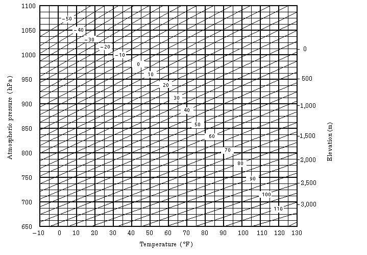
66 9-4 9 SETTING ATMOSPHERIC CORRECTION

67 9-5 9 SETTING ATMOSPHERIC CORRECTION
68 10 CORRECTION FOR REFRACTION AND EARTH CURVATURE 10 CORRECTION FOR REFRACTION AND EARTH CURVATURE The instrument measures distance, taking into account correction for refraction and earth curvature Distance Calculation Formula Distance Calculation Formula; with correction for refraction and earth curvature taken into account. Follow the Formula below for converting horizontal and vertical distances. Horizontal distance D = AC(α) or BE(β) Vertical distance Z = BC(α) or EA(β) D = L{cosα (2θ γ) sinα} Z = L{sinα+(θ γ) cosα} θ = L cosα/2r... Earth curvature correcting item γ =K Lcosα/2R... Atmospheric refraction correcting item K =0.14 or Coefficient of refraction R =6372km... Radius of earth α ( or β)... Altitude angle L... Slope distance The conversion formula for horizontal and vertical distances is as follows when correction for refraction and earth curvature is not applied. D=L cosα Z=L sinα Note: The coefficient of the instrument has been set at 0.14 before shipment (K=0.14). if the K value is to be changed, refer to 13 SELECTING MODE. 10-1
69 11 POWER SOURCE AND CHARGING 11.1 On-board Battery BT-52QA 11 POWER SOURCE AND CHARGING To remove Push the battery locking lever and pull out the BT-52QA on-board battery as shown below. To charge BT-52QA Outlet BC-27M 1 Connect the AC-cable to the charger. 2 Plug the AC-plug into the outlet. (The CHARGE lamp will light up in red.) 3 Connect the charger connector to the battery. Preparatory charging* will start. When the preparatory charging is completed, the charging status will be switched to quick charging automatically. (The CHARGE lamp will light up in orange.) 4 Charging will take approximately 1.8 hours. (The CHARGE lamp will light up in green.) 5 After charging, remove the battery from the charger. Remove the charger from the outlet. *About preparatory charging Before quick charging, the battery is charged using small amount current to measure its temperature and voltage. When the temperature and voltage is within a range, the charging status will change to quick charging. To refresh Press the refresh switch* after starting charging above steps 1, 2 or 3, then discharging will start. (The DISCHARGE lamp will light up in yellow.) After discharging is finished, charging will start automatically. Time discharging battery charged fully is approximately 9 hours. *For refreshing Rechargeable battery can be used repeatedly by charging. If charging is repeated by the state that capacity of the battery still left, operating time of the battery may shorten. In this case, the voltage of the battery will be recovered by refreshing and operating time can be improved. 11-1
70 11 POWER SOURCE AND CHARGING The lamp of charger(bc-27m) CHARGE Lamp Red ON : Waiting Orange blinking : Waiting until internal temperature falls Orange ON : Charging Orange lamp will light up during charging. Green ON : Charging completed Green lamp will light up after completely charging. Red blinking : Abnormal outbreaks Red lamp will flash when the battery life is over or the battery is broken down. Replace the battery to new one. DISCHARGE Lamp Yellow ON : Discharging Yellow lamp will light up and discharging will start by pressing the refresh (discharge) switch. To install Place the base of the on-board battery into the CTS-3000 series, push the on-board battery toward the instrument side till the battery clicks into position. Do not charge or discharge continuously, otherwise the battery and the charger may be deteriorated. If charging or discharging is necessary, use the charger after stopping charge for approximately 30 minutes. Do not charge the battery or discharge the battery in right after the battery is charged, it causes deterioration of the battery in rare cases. The charger may develop heat while charging, there is no problem of it. Note: 1 Recharging should take place in a room with an ambient temperature range of 10 C to 40 C (50 F to 104 F). 2 If charging is done at high temperature, charging time of the battery may take longer. 3 Exceeding the specified charging time may shorten the life of the battery and should be avoided if possible. 4 The battery source will discharge when stored and should be checked before using with instrument. 5 Be sure to charge as stored battery source every 3 or 4 months and store in a place at 30 C and below when it will not used for a long period. If you allow the battery to be completely discharged, it will have an effect on the overall performance for proper charging in the future. Keep batteries charged at all times. 6 For further information, see APPENDIX 2 Precaution when Charging or Storing Batteries. 11-2
71 12 DETACH/ATTACH OF TRIBRACH 12 DETACH/ATTACH OF TRIBRACH The instrument is easily detached or attached to the tribrach, with a tribrach locking lever loosened or tightened for this purpose. Detachment 1 Loosen the tribrach locking lever, by revolving it 180 or 200gon in the counterclockwise direction (which will point the triangle mark upwards). 2 Grip the carrying handle firmly with one hand while holding the tribrach with the other. Then lift the instrument straight upwards and off. Attachment 1 Hold the instrument by the carrying handle, with one hand, and carefully lower it on top of the tribrach while, at the same time, coinciding the alignment piece with the tribrach alignment groove on the instrument and tribrach respectively. 2 When fully seated, revolve the tribrach locking lever 180 or 200gon clockwise ( which will point the triangle mark downwards again). 3 Confirm that the upper instrument section is securely attached. Alignment piece Alignment groove Securing screw Tribrach locking lever Locking the Tribrach Locking Lever The tribrach locking lever can be locked, to prevent it be accidentally removed, especially if the upper instrument section is not being detached very often. Simply tighten the securing screw on the locking lever with the accessory screwdriver, found in the case. 12-1
72 13 SELECTING MODE 13 SELECTING MODE 13.1 Items of the Selecting Mode The following modes are available. Menu Items Selecting item Display 1: UNIT SET 2: MODE SET TEMP. & PRES. C / F hpa / mmhg / inhg ANGLE DEG(360 ) / GON(400G) / MIL(6400M) Select the unit of temperature for atmospheric correction. Select the unit of air pressure for atmospheric correction. Choose degree, gon or mil unit for measuring angle. DISTANCE m / ft / ft + in Choose measuring unit for distance meter, feet or feet and inch FEET US SURVEY / INTERNATIONAL POWER ON MODE FINE/CRS/ TRK ANGLE MEAS./ DISTANCE MEAS. FINE / COARSE / TRACK Select the meter / feet conversion factor. US SURVEY feet 1m= ft. INTERNATIONAL feet 1m= ft. Select to set the measurement mode for angle or distance when the power is turned on. Select Fine /Coarse / Tracking mode in distance measurement mode, when the power is turned on. HD&VD/SD HD&VD /SD Specify which is displayed first, horizontal and vertical distance or slope distance, when the power is turned on. V ANGLE Z0/ H0 N-TIMES / REPEAT TIMES OF MEAS. ZENITH 0 / HORIZONTAL 0 N-TIMES / REPEAT Choose the vertical angle reading from zenith or from level. Select the measurement mode for distance when the power is turned on. 0~99 Set N (number of times) for times of distance measurement. When setting number of times as 1or 0, it is single measurement. NEZ / ENZ NEZ / ENZ Select a coordinate displaying order either NEZ or ENZ. HA MEMORY ON / OFF Horizontal angle set can be retained after the power is turned off. ESC KEY MODE EDM OFF TIME REC /OFF You can select a function of the [ESC] key. REC: While executing normal or offset measuring, the measuring data can be output. OFF: Returns to normal function The time when EDM is cut off from distance measurement is completed can be changed. This function is effective for shortening the first time measuring time when distance measurement is started from distance measurement completing state. (Default:3minutes) 0 :After completing distance measurement, EDM is cut off immediately :EDM is cut off after 1~98 minutes. 99 :EDM is always switched ON. 13-1
73 13 SELECTING MODE 3: OTHERS SET FINE READING OFFSET V ANG NON-PSM / PRISM L.PL OFF TIME (Only for Laser plummet type) H-ANGLE BUZZER 0.2mm/1mm FREE / HOLD NON-PRISM / PRISM Select 1mm or 0.2mm for the minimum reading unit in the distance mode (FINE mode). Select Vertical angle setting in the Angle Offset measurement mode. FREE: Vertical angle varies by the angle of the telescope. HOLD: Vertical angle is fixed even if the angle of the telescope changes. Select the distance measurement mode when the power is turned ON Laser plummet function can be turned off automatically : Laser Plummet is cut off after 1 to 98 minutes. 99 : Manual ON / OFF Specify whether the buzzer sounds or not for every horizontal angle 90. S/A BUZZER ON / OFF Specify whether the buzzer sounds or not in the set audio mode. W- CORRECTION NEZ MEMORY OFF / 0.14 / 0.20 ON / OFF Set correction for refraction and earth curvature, coefficient of refraction as; K=0.14, K=0.20 or no correction. It is possible to retain the coordinate of instrument point, the instrument height and prism height after power off. REC TYPE REC-A / REC-B Select REC-A or REC-B for data output. REC-A : The measurement is made again and this new data is output. REC-B : The data being displayed is output. CR, LF ON / OFF It is possible to output the data with carriage return and line feed. NEZ REC FORM LANGUAGE *1 STANDARD / with RAW / STANDARD -12Dig / with RAW - 12Dig ENGLISH/ OTHER * ACK MODE STANDARD / OMITTED Select to record coordinates in standard or with raw data. Select the displaying language. Set the procedure of the communication with external device. STANDARD:Normal procedure OMITTED: Even though the [ACK] is omitted from the external device, the data is not sent again. ECHO BACK ON / OFF It is possible to output the data of echo back type. CONTRAST MENU PASSWORD *2 ON / OFF ON / OFF When the instrument is turned ON, it is possible to display the screen which you can adjust contrast of the display and confirm the prism constant (PSM), non-prism constant (NPM) and atmospheric correction value (PPM). When the instrument is turned ON, the screen to request the password will appear. *3 *1 LANGUAGE selection varies depending on countries. *2 Applicable only to the instruments with security function *3 If you forget a password, the instrument needs repair to cancel the password. Please contact Topcon or your local Topcon dealer. 13-2
74 13.2 How to Set Selecting Mode <Example>: Setting unit in hpa, F, NEZ MEMORY: ON 13 SELECTING MODE Operating procedure Operation Display 1 While pressing [F2] key, turn power ON. [F2] + Power ON 2 Press [F1](UNIT SET ) key. [F1] 3 Press [F1](TEMP. & PRES.) key. [F1] PARAMETERS 2 F1:UNIT SET F2:MODE SET F3:OTHERS SET UNIT SET 1/2 F1:TEMP. & PRES. F2:ANGLE F3:DISTANCE P TEMP. & PRES. UNIT TEMP. : C PRES. : mmhg C F ENTER 4 Press [F2]( F) key, and press [F4](ENTER) key. 5 Press [F1](hPa) key, and press [F4] (ENTER) key. Returns to unit set menu. 6 Press [ESC] key. Returns to PARAMETERS 2 menu. [F2] [F4] [F1] [F4] [ESC] TEMP. & PRES. UNIT TEMP. : F PRES. : mmhg hpa mmhg inhg ENTER UNIT SET 1/2 F1:TEMP. & PRES. F2:ANGLE F3:DISTANCE PARAMETERS 2 F1:UNIT SET F2:MODE SET F3:OTHERS SET 7 Press [F3](OTHERS SET) key. [F3] 8 Press [F4](P ) key, to get the function in page 2. [F4] OTHERS SET 1/4 F1:H-ANGLE BUZZER F2:S/A BUZZER F3:W-CORRECTION P OTHERS SET 2/4 F1:NEZ MEMORY F2:REC TYPE F3:CR,LF P 9 Press [F1] key. [F1] NEZ MEMORY [OFF] 10 Press [F1](ON) key, and press [F4] (ENTER) key. Returns to OTHERS SET menu. [F1] [F4] [ON] [OFF] ENTER OTHERS SET 2/4 F1:NEZ MEMORY F2:REC TYPE F3:CR,LF P 11 Power off Power OFF 13-3
75 14 CHECK AND ADJUSTMENT 14.1 Checking and adjusting of instrument constant 14 CHECK AND ADJUSTMENT Note: Each of the Prism mode and Non-prism mode has instrument constant. You must obtain the instrument constant of prism mode. If you reset the instrument constant of the prism mode, you must vary the non-prism constant (NON-PRISM) by the same quantity as the amount of increase or decrease of the instrument constant of the prism mode. Normally, the instrument constant does not have discrepancy. It is recommended you measure and compare with an accurately measured distance at a location where the precision is specifically monitored on a consistent basis. If such a location is not available, establish your own base line over 20m (when purchasing the instrument) and compare with the data measured with newly purchased instrument. In both cases note that the setup displacement of the instrument position over the point, the prism or target, baseline precision, poor collimation, atmospheric correction, and correction for refraction and earth curvature determine the inspection precision. Please keep in mind these points. Also, when providing a base line in a building, please note that the difference in temperature greatly changes the length measured in the building. If the difference between the measured length of the baseline and the actual length exceeds the range of the nominal accuracy, change the instrument constant of the prism mode according to the following procedure. 1) On a basically horizontal line of about 100 meters, line AB, establish point C. Measure each distance, AB, AC and BC, about 10 times, and calculate the average value for each. A C B 2) Repeat Step 1 several times. Then calculate the variance with the current instrument constant (ΔK). ΔK = AB - (AC + BC) 3) Calculate the new instrument constant according to the formula below. Then reset the instrument constant according to Section 14.4 How to Set the Instrument Constant Value New instrument constant = current instrument constant + ΔK 4) Once again, measure the baseline and compare the results to the baseline s actual length. Repeat the same procedure in non-prism mode as well. 5) If the results of the measurement conducted in Step 4 exceed the range of the nominal accuracy, contact TOPCON or your TOPCON dealer. 14-1
76 14.2 Checking the Optical Axis 14 CHECK AND ADJUSTMENT Checking the optical axis of EDM and theodolite Check each of the optical axis of EDM and theodolite about prism mode and non-prism mode in order. To check if the optical axis of EDM and theodolite are matched, follow the procedure below. It is especially important to check after adjustment of the eyepiece reticle is carried out. 1) Position a prism about 30 to 50m apart from CTS-3000 series. 2)Turn the power ON while pressing the [F1] key. ADJUSTMENT MODE 1/2 Adjustment mode menu 1/2 will appear. F1:V ANGLE 0 POINT F2:INST. CONSTANT F3:V0 AXIS P ADJUSTMENT MODE 2/2 F1:EDM CHECK 3)Press the [F4](P ) key to get the menu 2/2. Press the [F1] key to select the EDM CHECK mode. P V: 90 10'10" HR: 20 00'20" SIGNAL:[IIIII] EXIT NP/P HOLD V: 90 10'10" HR: 00 04'20" SIGNAL:[IIIII] # EXIT NP/P HOLD 4)Collimate the center of a prism by prism mode. The buzzer will sound. 5)Press the [F4](hold) key to hold the quantity of the light. The mark # will appear on the right side of the signal level indicator. H direction confirmation (Do not move V direction). 6) Turn the horizon tangent screw, move the collimating point to the left side of prism gradually until buzzer sound stops. Prism Reticle 14-2
77 14 CHECK AND ADJUSTMENT 7) Turn the horizontal tangent screw slowly, and move the collimating point to the prism center gradually until at the position buzzer starts. Confirm the level of the signal (light quantity level) in display to adjust at the level of one to two as shown in below by turning the horizontal tangent screw. Prism Reticle 8) Press the [ESC] key and measure the horizontal angle, and note the horizontal angle displayed. Or you can do 0-set of horizontal angle. 9) Return to the Set Audio mode again. 10) Turn the horizon tangent screw, move the collimating point to the right side of prism gradually until buzzer sound stops. Prism V: 90 10'10" HR: 00 01'20" SIGNAL:[II ] # EXIT NP/P HOLD Quantity level two Reticle 11) Move the collimating point to the center of prism gradually until buzzer sound starts. Turning the horizontal tangent screw to be one to two level of SIG value to adjust the collimating point same as step 6 procedure. 12) Note horizontal angle same as step 6 procedure. 13) Calculate the horizontal angle of center of the prism by step 7 and 11. [Example] Step 7 : Step 11: 0 01'20" 0 09'40" Calculated value 0 04'10" 14) Climate to the center of prism. Compare the reading horizontal angle and calculated average value in step 12. [Example] Horizontal angle of the center of the prism: 0 04'30" Difference of Average value and Horizontal reading of the center of the prism : 20" If the difference is within 2', no problem for use. 14-3
78 Vertical direction confirmation (Do not move Horizontal direction). 14 CHECK AND ADJUSTMENT 15) Carry out as Horizontal direction confirmation. Compare the reading vertical angle of center of prism and calculated average value. If the difference is within 2', no problem for use. Prism Reticle [Example] Lower side of prism 90 12'30" Upper side of prism 90 04'30" Average 90 08'30" Reading to prism center 90 08'50" Difference 20" If the difference is more than mentioned value, contact with your Topcon dealer or Topcon. For non-prism mode If the instrument is in the hold mode, press the [F4](HOLD) key to release the hold mode. V: 90 10'10" N HR: 00 04'20" P SIGNAL:[IIIII] # EXIT NP/P HOLD V: 90 10'10" HR: 00 04'20" N P SIGNAL:[IIIII] # EXIT NP/P HOLD 16)Press the [F3](NP/P) key to change the nonprism mode. 17)Collimate the center of the prism. 18)Press the [F4](hold) key to hold the quantity of the light. The mark # will appear on the right side of the signal level indicator. 19)Repeat above procedure 6 to 15 in the same way in the non-prism mode. If the difference is within 2', no problem for use. If the difference is more than mentioned value, contact with your Topcon dealer or Topcon. 14-4
79 14 CHECK AND ADJUSTMENT Checking the optical axis of Laser pointer Check whether the optical axis of the laser pointer coincides with the optical axis of the telescope by carrying out the following steps. The laser pointer indicates the approximate collimation position of the telescope. It does not indicate the exact collimation position. Therefore, it is not failure of the CTS-3000 although it may shift to 6mm by the optical axis and laser point on the target about 10 meters from the CTS ) On the center of a piece of graph paper or white paper, draw a target in the form of a vertical line and an intersecting horizontal line. 2) Set up the target about 10 meters from the CTS-3000, and collimate the CTS-3000 to the point of intersection of the two lines. 3) Turn on power to the CTS-3000, press the star key mode, and then press the L. P. key, lighting up the laser pointer. Target About10m Checking of laser pointer s optical axis 4) With the CTS-3000 collimated to the point of intersection of the two lines, check whether the center of the laser pointer is within about 6 mm of the point of intersection. Note: If you look through the telescope at this time, you will not be able to see the laser pointer. Therefore, conduct this check with the naked eye, viewing the target and the laser pointer from the side of, or from above, the CTS ) If the center of the laser pointer is within about 6 mm of the point of intersection, there will be no problems with using the CTS If the distance is greater than 6 mm, carry out the following steps to align the center of the laser pointer with the point of intersection, and to align the laser pointer s optical axis with that of the telescope. Adjusting the laser pointer s optical axis 6) As shown in the drawing, remove the 3 rubber caps on top of the instrument, revealing the adjustment screws. 7) Using the accessory hexagonal wrench, adjust each of the screws - A, B and C - thereby moving the laser pointer so that it coincides with the point of intersection. 14-5
80 14 CHECK AND ADJUSTMENT About30 About30 The direction of the laser pointer As seen from above Adjustment screws when screws A, B and C are turned clockwise (the direction for tightening them), the laser pointer, as seen on the target from the standpoint of the CTS-3000, will move in the direction shown in the drawing. Tighten the 3 screws so that they are equally tight. Do not lose the rubber caps of the adjustment screws. 14-6
81 14.3 Checking/Adjusting the Theodolite Functions 14 CHECK AND ADJUSTMENT Pointers on the Adjustment 1) Adjust the eyepiece of the telescope properly prior to any checking operation which involves sighting through the telescope. Remember to focus properly, with parallax completely eliminated. 2) Carry out the adjustments in the order of item numbers, as the adjustments are dependent one upon another. Adjustments carried out in the wrong sequence may even nullify previous adjustment. 3) Always conclude adjustments by tightening the adjustment screws securely (but do not tighten them more than necessary, as you may strip the threads, twist off the screw or place undue stress on the parts). Furthermore, always tighten by revolving in the direction of tightening tension. 4) The attachment screws must also be tightened sufficiently, upon completion of adjustments. 5) Always repeat checking operations after adjustments are made, in order to confirm results. Notes on the Tribrach Note that the angle measuring precision may be effected directly if the tribrach has not been installed firmly. 1) If any leveling screw becomes loose and slack or if collimation is unstable due to the looseness of leveling screws, adjust by tightening the adjusting screws (in 2 places) installed over each leveling screw with a screwdriver 2) If there is any slack between the leveling screws and the base, loosen the set screw of the holding ring and tighten the holding ring with adjusting pin, until it is properly adjusted. Re-tighten the set screw on completing the adjustment. Adjustment screw Adjustment screw Leveling screw Holding ring Set screw 14-7
82 14 CHECK AND ADJUSTMENT Checking /Adjusting the Plate Level Adjustment is required if the axis of the plate level is not perpendicular to the vertical axis. Check 1) Place the plate level parallel to a line running through the centers of two leveling screws, say, A and B. Use these two leveling screws only and place the bubble in the center of the plate level. 2) Rotate the instrument 180 or 200g around the vertical axis and check bubble movement of the plate level. If the bubble has been displaced, then proceed with the following adjustment. Plate level Leveling screw A Leveling screw B Adjustment 1) Adjust the level adjustment capstan screw, with the accessory adjusting pin and return the bubble towards the center of the plate level. Correct only one-half of the displacement by this method. 2) Correct the remaining amount of the bubble displacement with the leveling screws. 3) Rotate the instrument 180 or 200g around the vertical axis once more and check bubble movement. If the bubble is still displaced, then repeat the adjustment. Level adjustment capstan screw Total amount of displacement Half amount of displacement Checking /Adjusting the Circular Level Adjustment is required if the axis of the circular level is also not perpendicular to the vertical axis. Check Carefully level the instrument with the plate level only. If the bubble of the circular level is centered properly, adjustment is not required. Otherwise, proceed with the following adjustment. Adjustment Shift the bubble to the center of the circular level, by adjusting three capstan adjustment screws on the bottom surface of the circular level, with the accessory adjusting pin. Capstan adjustment screws Bottom of the base Circular level 14-8
83 14 CHECK AND ADJUSTMENT Adjustment of the Vertical Cross-hair Adjustment is required if the vertical cross-hair is not in a place perpendicular to the horizontal axis of the telescope (since it must be possible to use any point on the hair for measuring horizontal angles or running lines). Check 1) Set the instrument up the tripod and carefully level it. 2) Sight the cross-hairs on a well defined Point A at a distance of, at least, 50 meters (160ft.) and clamp horizontal motion. 3) Next swing the telescope vertically using the vertical tangent screw, and check whether the point travels along the length of the vertical cross-hair. 4) If the point appears to move continuously on the hair, the vertical cross-hair lies in a plane perpendicular to the horizontal axis (and adjustment is not required ). 5) However, if the point appears to be displaced from the vertical cross-hair, as the telescope is swung vertically, then proceed with the following adjustment. Adjustment 1) Unscrew the cross-hair adjustment section cover, by revolving it in the counterclockwise direction, and take it off. This will expose four eyepiece section attachment screws. Eyepiece section attachment screws Eyepiece section attachment screws Eyepiece 2) Loosen all four attachment screws slightly with the accessory screw-drive (while taking note of the number of revolutions). Then revolve the eyepiece section so that the vertical cross-hair coincides to Point A. Finally, re-tighten the four screws by the amount that they were loosened. 3) Check once more and if the point travels the entire length of the vertical cross-hair, further adjustment is not required. Note: Perform following adjustment after completing the above adjustment. Section Collimation of the Instrument, Section Adjustment of Vertical Angle 0 Datum. 14-9
84 14 CHECK AND ADJUSTMENT Collimation of the Instrument Collimation is required to make the line of sight of the telescope perpendicular to the horizontal axis of the instrument, otherwise, it will not be possible to extend a straight line by direct means. Check Eyepiece 1) Set the instrument up with clear sights of about 50 to 60meters (160 to 200 ft.) on both sides of the instrument. 2) Level the instrument properly with the plate level. 3) Sight Point A at approximately 50 meters (160 ft.) distance. Telescope 4) Loosen the vertical motion clamp only, and rotate the telescope 180 or 200g around the horizontal axis, so that the telescope is pointed in the opposite direction. 5) Sight Point B, at equal distance as Point A and tighten the vertical motion clamp. 6) Loosen the horizontal motion clamp and rotate the instrument 180 or 200g around the vertical axis. Fix a sight on Point A once more and tighten the horizontal motion clamp. 7) Loosen the vertical motion clamp only and rotate the telescope 180 or 200g around the horizontal axis once more and fix a sight on Point C, which should coincide with previous Point B. 8) If Points B and C do not coincide, adjust in the following manner. Adjustment 1) Unscrew the cross-hair adjustment section cover. 2) Find Point D at a point between Points C and B, which should be equal to 1/4th the distance between Points B and C and measured from Point C. This is because the apparent error between Points B and C is four times the actual error since the telescope has been reversed twice during the checking operation. Capstan adjustment screws 3)Shift the vertical cross-hair line and coincide it with Point D, by revolving the left and right capstan adjustment screws with the adjusting pin. Upon completing the adjustment, repeat the checking operation once more. If Points B and C coincide, further adjustment is not required. Otherwise, repeat the adjustment. Capstan adjustment screws Eyepiece 14-10
85 14 CHECK AND ADJUSTMENT Note: 1 First, loosen the capstan adjustment screw on the side to which the vertical cross-hair line must be moved. Then tighten the adjustment screw on the opposite side by an equal amount which will leave the tension of the adjustment screws unchanged. Revolve in the counterclockwise direction to loosen and in the clockwise direction to tighten, but revolve as little as possible. 2 Perform following adjustment after completing above adjustment. Section Adjustment of Vertical Angle 0 Datum, Section 14.2 Checking the Optical Axis Checking / Adjusting the Optical Plummet Telescope Adjustment is required to make the line of sight of the optical plummet telescope coincide with the vertical axis (otherwise the vertical axis will not be in the true vertical when the instrument is optically plumbed). Check 1) Coincide the center mark and the point. (See Chapter 2 PREPARATION FOR MEASUREMENT.) 2) Rotate the instrument 180 or 200g around the vertical axis and check the center mark. If the point is properly centered in the center mark, adjustment is not required. Otherwise, adjust in the following manner. Adjustment 1) Take off the adjustment section cover of the optical plummet telescope eyepiece. This will expose four capstan adjustment screws which should be adjusted with the accessory adjusting pin to shift the center mark to the point. However, correct only one-half of the displacement in this manner. Capstan adjustment screws Total amount of displacement Capstan adjustment screws Plummet telescope Eyepiece Half amount of displacement 2) Use the leveling screws and coincide the point and center mark. 3) Rotate the instrument 180 or 200g around the vertical axis once more and check the center mark. If it is coincided to the point, then further adjustment is not required. Otherwise, repeat the adjustment. Note: First, loosen the capstan adjustment screw on the side to which the center mark must be moved. Then tighten the adjustment screw on the opposite side by an equal amount which will leave the tension of the adjustment screws unchanged. Revolve in the counterclockwise direction to loosen and in the clockwise direction to tighten, but revolve as little as possible
86 14 CHECK AND ADJUSTMENT Checking / Adjusting the Laser Plummet (For Laser Plummet type) Check 1) Turn on the laser plummet and coincide the center of the laser with a measuring point. 2) Rotate the instrument 180 or 200g around the vertical axis and check the measuring point. If the laser is properly centered in the measuring point, adjustment is not required. Otherwise, adjust in the following manner. Adjustment 1) Turn the cap located on the left side corner of the instrument counterclockwise and remove it. This will expose four adjustment screws which should be adjusted with the accessory hexagonal wrench. 2) Shift the laser to the measuring point. However, correct only one-half of the displacement in this manner. Cap Adjustment screws Laser beam Total amount of displacement Half amount of displacement Adjustment screws Measuring point 3) Use the leveling screws and coincide the center of the laser and the point. 4) Rotate the instrument 180 or 200g around the vertical axis once more and check the point and the laser. If the laser is coincided to the measuring point, then further adjustment is not required. Otherwise, repeat the adjustment. Note: First, loosen the adjustment screw to move the laser. Then tighten the adjustment screw on the opposite side by an equal amount which will leave the tension of the adjustment screws unchanged. Revolve in the counterclockwise direction to loosen and in the clockwise direction to tighten, but revolve as little as possible. Reference The laser can be moved by turning the adjustment screws clockwise as follows. Laser is moved down. Laser beam Laser is moved left. Laser is moved right. Adjustment screws Laser is moved up. Top of view of the measuring point 14-12
87 14 CHECK AND ADJUSTMENT Adjustment of Vertical Angle 0 Datum If when measuring the vertical angle of target A at telescope position normal (direct) and reverse settings, the amount of normal and reverse measurements combined is other than 360 (ZENITH-0), half of the difference from 360 is the error amount from corrected 0 setting. Carry out adjustment. As adjustment for vertical angle 0 setting is the criteria for determining instrument coordinate origin, use special care for adjustment. Operating procedure Operation Display 1 Level the instrument properly with the plate level. 2 While pressing the [F1]key, turn power switch ON. [F1] + Power ON ADJUSTMENT MODE 1/2 F1:V ANGLE 0 POINT F2:INST. CONSTANT F3:V0 AXIS P 3 Press the [F1] key. [F1] V0 ADJUSTMENT <STEP-1> FRONT V: 90 00'00" ENTER 4 Collimate target A from the telescope properly in normal setting. 5 Press the [F4](ENTER) key. 6 Collimate target A in reverse telescope setting. 7 Press the [F4](ENTER) key. Measured value is set and carry out normal angle measurement. Collimate A (Normal) [F4] Collimate A (Reverse) [F4] V0 ADJUSTMENT <STEP-2> REVERSE V: '00" ENTER <SET!> 8 Check that the total amount of normal and reverse angular travel is 360 collimating the target A by normal and reverse positions. V : '00" HR: '40" 0SET HOLD HSET P
88 14.4 How to Set the Instrument Constant Value 14 CHECK AND ADJUSTMENT To set the Instrument constant which is obtained in Section 14.1 Checking and adjusting of instrument constant, follow as below. Note: Each of the Prism mode and Non-prism mode has instrument constant. You must check the instrument constants in each mode and obtain the instrument constants of Prism mode and Non-prism mode. Operating procedure Operation Display 1 While pressing the [F1] key, turn power switch ON. [F1] + POWER ON 2 Press the [F2] key. [F2] ADJUSTMENT MODE F1:V ANGLE 0 POINT F2:INST. CONSTANT F3:V0 AXIS P INST. CONSTANT SET F1:PRISM F2:NON-PRISM 3 Select the constant value by pressing the [F1] or [F2] key. [F1] or [F2] INST. CONSTANT SET NON-PRISM = mm [CLR] [ENT] 4 Enter the constant value. *1),2) Enter value [F4] INST. CONSTANT SET NON-PRISM : mm INPUT ENTER 5 Turn power switch OFF. Power OFF *1) Refer to Section 2.6 How to Enter Alphanumeric characters. *2) To cancel the setting, press the [ESC] key
89 14 CHECK AND ADJUSTMENT 14.5 Adjustment of Compensation Systematic Error of Instrument (Only for CTS-3005) Operating procedure Operation Display 1 Level the instrument properly with the plate level. 2 While pressing the [F1] key, turn power switch ON. [F1] + Power ON ADJUSTMENT MODE 1/2 F1:V ANGLE 0 POINT F2:INST. CONSTANT F3:V0 AXIS P 3 Press the [F3] key. [F3] AV0 AXIS F1:MEASUREMENT F2:CONSTANT LIST 4 Press the [F1] key. [F1] V0/AXIS ADJUSTMENTS ERROR CORRECTION (A)COLLIMATION (B)H AXIS 5 Collimate target A (around 0 in horizontal within ±3 ) in normal telescope setting (FACE (1)). 6 Press the [F4](SET) key. *1) The sample display shows that the measurement is made 5 times in FACE 1. 7 Turn the telescope in reverse telescope setting (FACE (2)). 8 Collimate target A. Collimate A (Normal) [F4] Turn telescope Collimate A (Reverse) FRONT FACE1 /0 V: 89 55'50" LEVEL ±0 SKIP SET REVERSE FACE2 /5 V: '20" LEVEL ±0 SET 9 Press the [F4](SET) key. Repeat the procedures in step 8 and 9 so that the count of measured times matches to the one in FACE(1). *2),3),4) The title display will be shown automatically. 10 Collimate target B (more than ±10 from the level) in reverse telescope setting (FACE(2)). *5) 11 Press the [F4](SET) key. *5) [F4] Collimate B (Reverse) [F4] (B)HORIZONTAL AXIS REVERSE FACE 2 /0 V: '20" LEVEL ±10 SET 14-15
90 14 CHECK AND ADJUSTMENT 12 Turn the telescope in normal telescope setting (FACE(1)). 13 Collimate target B. Turn telescope Collimate B (Normal) FRONT FACE 1 /5 V: 89 55'50" LEVEL ±10 SKIP SET 14 Press the [F4](SET) key. Repeat the procedures in step 13 and 14 so that the count of measured times matches to the one in FACE(2). Then the display returns to main menu. [F4] COMPLETE To show the constant list of systematic error of instrument 1 Press the [F3] key from Adjustment Mode menu 1/ 2. [F3] ADJUSTMENT MODE 1/2 F1:V ANGLE 0 POINT F2:INST. CONSTANT F3:V0 AXIS P V0 AXIS F1:MEASUREMENT F2:CONSTANT LIST 2 Press the [F2] key. Correction values are displayed. 3 Press the [F1] key. The display returns to previous menu. [F2] [F1] VCo: -1 57'12" HCo: -0 00'20" HAx: -0 00'20" EXIT *1) It is able to get the average value from 1 to 10 measurements. To get the average, repeat the procedures in steps 5, 6 or 10, 11. The measured times is counted in the second line of display. *2) The compensation values of 1) Error of vertical axis (X,Y tilt sensor offset), 2) Collimation error, and 3) Error of vertical angle 0datum will be set and memorized internally. *3) The operating procedure steps to set compensation value of 4) Error of horizontal axis. *4) Pressing the [F1](SKIP) key enables to set next step without changing the last compensated value. *5) Pressing the [F1](SKIP) key makes end of setting without changing compensation value
91 14.6 EDM Alignment Checking mode 14 CHECK AND ADJUSTMENT This mode is used for check the optical axis and EDM axis. For more information about the checking, see Section Checking the optical axis of EDM and theodolite. Operating procedure Operation Display 1 While pressing the [F1] key, turn power switch ON. [F1] + Power ON 2 Press the [F4] key. [F4] ADJUSTMENT MODE 1/2 F1:V ANGLE 0 POINT F2:INST. CONSTANT F3:V0 AXIS P ADJUSTMENT MODE 2/2 F1:EDM CHECK 3 Press the [F1] key. EDM checking mode will display. [F1] P V: 90 10'10" HR: 20 00'20" SIGNAL:[IIIII] EXIT NP/P HOLD 14-17
92 15 PRECAUTIONS 15 PRECAUTIONS 1) For transportation, hold by the handle or yoke of the instrument. Never hold by the lens barrel as it can affect the fixing bracket inside and reduce the accuracy of the instrument. 2) Never expose the instrument without a filter to direct sunlight. It may damage the components inside the instrument. 3) Never leave the instrument unprotected in high temperature. The temperature inside instrument may easily reach up to 70 C or above and will reduce the service life. 4) The instrument should be stored in the room temperature range of minus 30 C to plus 60 C. 5) When a high degree of precision is required for measurement, provide shade against direct sunlight for the instrument and tripod. 6) Any sudden change of temperature to the instrument or prism may result in a reduction of measuring distance range, i.e. when taking the instrument out from a heated vehicle. 7) When opening the carrying case and taking out the instrument, place the case horizontally, then open the case. 8) When returning the instrument to its case, be sure to match the white positioning marks provided with the case and fit it correctly into the concave shape inside the case. 9) For transportation, provide dampening or a cushion appropriately to avoid sudden shock or vibration. 10) For cleaning the instrument after use, remove dust using a cleaning brush, then wipe off with a cloth. 11) For cleaning the lens surface, use a cleaning brush to remove the dust, then use a clean lintless cotton cloth. Moisten it with alcohol (or mixture with ether ) to wipe gently in a rotational motion from the center out. 12) Even if any abnormality occurs, never attempt to disassemble or lubricate the instrument yourself. Always consult with TOPCON or your dealer. 13) To remove the dust on the case, never use thinner or benzine. Use a clean cloth moistened with neutral detergent. 14) Check each part of the tripod after extended use. Parts (screws or clamps) may work themselves free. 15-1
93 16 SPECIAL ACCESSORIES 16 SPECIAL ACCESSORIES Power cord PC-5 (For AC-6) Cord length: 2m approx. Power cord PC-6 (For BT-3L, AC-6) Cord length: 2m approx. Trough compass, Model 6 Shock proof construction. No clamp is necessary when carrying the instrument. Solar reticle, Model 6 A reticle designed for collimation of the sun. Can be used together with Solar Filter. Diagonal eyepiece, Model 10 Observation in an easy posture will be provided up to the zenith position Solar filter, Model 6 A filter designed exclusively for direct collimation of the sun. Solar filter of flap-up type. 16-1
94 16 SPECIAL ACCESSORIES Prism unit case, Model 6 Fixed 9 prisms unit or tilting 3 prisms unit can be stored in this case. Especially, this is a very easy case to carry. Soft material is used. External dimensions: 250(L) 120(W) 400(H) mm Weight: 0.5kg Prism unit case, Model 5 1 prisms unit or fixed 3 prisms unit can be stored in this case. Especially, this is a very easy case to carry. Soft material is used. External dimensions: 200(L) 200(W) 350(H) mm Weight: 0.5kg Prism unit case, Model 3 This is the plastic case to store and carry various sets of prisms. The case covers one of the following prism sets: 1) Tilt single prism set 2) Tilt single prism set with a target plate 3) Fixed triple prism unit 4) Fixed triple prism unit with a target plate External dimensions: 427(L) 254(W) 242(H) mm Weight: 3.1kg Back pack, Model 2 Convenient for use in mountainous terrain. Interface cable F-24 Cable for communicating an external instrument and CTS-3000 by the serial signal connector. Large capacity battery pack BT-3L Output voltage: DC 8.4V Capacity: 6AH External dimensions: 190(L) 106(W) 74(H) mm Weight: 2.8kg 16-2
95 16 SPECIAL ACCESSORIES Auto Converter AC-6 Input voltage: DC12V Output voltage: DC 8.4V±5% Current rating: 3A Connection cable length: Approx. 3m External dimensions: 100(L) 50(W) 52(H) mm Weight: Approx. 0.3kg Battery charger BC-6 (for BT-3L) Input voltage:ac100, 120, 220, 240V ±10% 50/60 Hz Power consumption: 15VA approx. Charging time: approx. 15 hour (+20 C) to charge BT-3L Operation temperature range: +10 C to +40 C (+50 to +104 F) External dimensions: 142(L) 96(W) 64(H) mm Weight: 1.0kg Mini prism The mini prism (25.4mm) is made from precision ground glass and mounted in high impact plastic housings. The mini has the unique capability of being positioned either at a 0 or 30 with the same prism Optical plummet tribrach This is detachable tribrach having built-in optical plummet telescope. (Compatible with Wild) Prism sets See the description on 18 PRISM SYSTEM. Aluminum extension leg tripod, Type E Flat head 5/8" 11 threads with adjustable legs. Wide-frame extension leg tripod, Type E (Wood) Flat head 5/8" 11 threads with adjustable legs. 16-3
96 17 BATTERY SYSTEM 17 BATTERY SYSTEM In case of On-board battery BT-52QA CTS-3000 series In case of External battery Battery pack Cord BT-3L PC-6 PC-5, PC-6 External 12V battery CTS-3000 series AC-6 Charging Battery pack Charging time Charger Quick V~ BC-27M In North America, use only 120V ~. Approx. 1.8h Use an AC cable compatible with the power supply voltage in use. BT-52QA Note: Use only recommended batteries or external power source. Use of batteries or an external power source not recommended by us may result in equipment failure. 17-1
97 18 PRISM SYSTEM 18 PRISM SYSTEM Arrangement according to your needs is possible. Target pole-2 (not used with 9 prisms) Prism-2 Tilting prism holder-2 with target plate-2 Tilting prism holder-3 Single prism holder-2 Triple prism holder-2 Tilting triple prism holder-1 9 prism holder-2 Pole adaptor- A Tribrach adaptor-2 Tribrach adaptor-s2 Pole adaptor- F2 Tribrach Optical plummet tribrach It is possible to change the combination according purpose. Tilt single prism unit Fixed 3 prisms unit Fixed 9 prisms unit Tripod Use the above prisms after setting them at the same height as the instruments. To adjust the height of prism set, change the position of 4 fixing screws. 18-1
98 19 ERROR DISPLAYS 19 ERROR DISPLAYS Error code Description Countermeasures 3 points required CALC ERROR DELETE ERROR SIGNAL OVER E35 E60 s E71 E72 E73 E80 s E90 s FILE EXISTS FULL FILES FAILED INITIALIZE LIMIT OVER When area calculating, there are less than 3 points coordinate data in selected file. Calculation is impossible from the data input. When deleting coordinate data, it can not be done successful. Displayed when you measure a prism of short distance with non-prism mode, or when the telescope received too much light. Displayed when REM measurement carried out to the range from zenith or nadir ±6. Any abnormality occurs with EDM (distance measuring system). Displayed when vertical angle 0 position is set with incorrect procedure. Displayed when Vertical angle -position is adjusted in wrong position. The instrument was not leveled when Vertical angle 0-position is adjusted. Mainly at the time data transmission between CTS-3000 series and external instrument. Abnormality in internal memory system. The same file name exists. When making a file, 30 files already exist. Initializing can not be done successful. Limit of input data exceeded. Confirm the file data and calculate again. Confirm the input data. Confirm the data and delete again. Measure the distance by using a target without using a prism, or change the mode from non-prism mode to prism mode. Operate in the range out of ± 6 from the zenith or nadir. Repair is required. Confirm the procedure and readjust. Repair is required. Level the instrument then carry the adjustment work. Confirm operation procedure is correct or the connection cables are correct. Repair is required. Use another file name. If necessary, send or delete files. Confirm initializing data and try to initialize again. Input again. MEMORY ERROR MEMORY POOR NO DATA Any abnormality occurs with internal memory. Shortage of capacity of the internal memory. The data is not found in the search mode Initialize the internal memory. Download data from internal memory to PC. Confirm the data and search again. NO FILE There is no file in internal memory. If necessary, make files. FILE NOT SELECTED When using a file, no file is selected. Confirm the file and select a file. P1-P2 distance too short When in point to line measurement, the horizontal distance between first point and second point is within 1m. The horizontal distance between first point and second point must be more than 1m. 19-1
99 CIRCULAR ERROR PT# EXIST PT# DOES NOT EXIST RANGE ERROR Tilt Over V ANGLE ERROR H ANGLE ERROR VH ANGLE ERROR Known points and occupied point are on the same circle at the resection mode. Same new point name is already memorized in the memory. When you enter incorrect name or PT# does not exist in the internal memory. When setting a new point, calculation is impossible from the measured data. Instrument tilts over more than 3 minutes. Abnormality in angle measuring system. Take the different point. 19 ERROR DISPLAYS Confirm the new point name and input again. Enter the correct name or enter point in the internal memory. Measure again. Level the instrument properly. If this error code continues to display, repair is required. If error still persist after attempting to clear them, contact your local Topcon dealer or Topcon head office. 19-2
100 20 SPECIFICATIONS Telescope Length : 150mm Objective lens : 45mm (EDM 50mm) Magnification : 30 Image : Erect Field of view : 1 30' Resolving power : 2.8" Minimum focus : 1.3m Reticle illumination : Provided 20 SPECIFICATIONS Distance measurement Measurement range Non-prism mode Target Kodak gray card (White surface) Atmospheric conditions In low light condition and without sun glare on target 1.5m to 250 m (5 ft to 820 ft) Prism mode Prism Atmospheric conditions Condition 1 1 prism 3,000m (9,900ft) Condition 1: Slight haze with visibility about 20km (12.5miles) moderate sunlight with light heat shimmer. Measurement accuracy Non-prism mode (Diffusing Surface) 1.5m to 25m (5ft to 82ft) : ± (10mm) m.s.e. 25m or more (82ft or more) : ± (5mm) m.s.e. Prism mode : ±(3mm +2ppm D) m.s.e. D: Measuring distance (mm) Laser class for distance measurement : Class 1(IEC Publication ) : Class I(FDA/BHR 21 CFR 1040) Least Count in Measurement Fine measurement mode : 1mm (0.005ft.) / 0.2mm (0.001ft.) Coarse measurement mode : 10mm (0.02ft.) / 1mm (0.005ft.) Tracking measurement mode : 10mm (0.02ft.) Measurement Display : 12 digits : max. display Measurement Time Fine measurement mode : 1mm : Approx. 1.2sec. (Initial 3 sec.) 0.2mm : Approx. 3 sec. (Initial 4 sec.) Coarse measurement mode : Approx. 0.5sec. (Initial 2.5 sec.) Tracking measurement mode : Approx. 0.3sec. (Initial 2.5 sec.) (The initial time will be different by a condition and setting EDM off time. ) 20-1
101 20 SPECIFICATIONS Atmospheric Correction Range Prism Constant Correction Range Coefficient Factor Electronic Angle Measurement Method Detecting system Horizontal angle CTS-3005 CTS-3007 Vertical angle : ppm to ppm, in 0.1 ppm increments : 99.9 mm to mm, in 0.1 mm increments : Meter / Feet International feet 1meter = ft. US SURVEY feet 1meter = ft. : Absolute reading : 2 sides : 1 side : 1 side Minimum reading CTS-3005 : 5" / 1" (1mgon / 0.2mgon) reading CTS-3007 : 10" / 5" (2mgon / 1mgon) reading Accuracy (Standard deviation based on DIN ) CTS-3005 : 5"(1.5mgon) CTS-3007 : 7"(2mgon) Measuring time : Less than 0.3 sec. Diameter of circle : 71mm Tilt Correction (Automatic index) Tilt sensor CTS-3005 CTS-3007 Method Compensating Range Correction unit Others Instrument height Level sensitivity Circular level Plate level CTS-3005 CTS-3007 : Automatic vertical and horizontal compensator : Automatic vertical compensator : Liquid type : ±3' : 1" (0.1mgon) : 176mm (6.93in) Base unit detachable (Height from the tribrach dish to the center of telescope) : 10'/2mm : 30"/2 mm : 40"/2 mm Optical Plummet Telescope Magnification : 3 Focusing range : 0.5m to infinity Image : Erect Field of view : 5 (ø114mm/1.3m) Laser pointer Light source : LD (Visible laser) Wave length : 690nm Out put : 1mW maximum Laser class : Class 2(IEC Publication ) : Class II(FDA/BHR 21 CFR 1040) Laser Plummet (only for Laser plummet type) Light source : LD (Visible laser) Wave length : 633nm Out put : 1mW maximum Laser class : Class 2(IEC Publication ) : Class II(FDA/BHR 21 CFR 1040) 20-2
102 20 SPECIFICATIONS Dimension Weight Instrument (with battery) (without battery) Plastic carrying case Durability Protection against water and dust Ambient Temperature Range External Battery Input voltage : 336(H) 184(W) 172(L) mm (13.2(H) 7.2(W) 6.8(L) in) : 5.3kg (11.6 lbs) : 5.0kg (11.0 lbs) : 3.4kg (7.5 lbs) (Weight of the carrying case may be slightly different due to specific market.) : IP66 (with BT-52QA) (Based on the standard IEC60529) : 20 C to +50 C ( 4 F to +122 F) : DC V Battery BT-52QA (This battery does not contain mercury.) Out put voltage : 7.2 V Capacity : 2,700 mah (Ni-MH) Number of cells : 6 Weight : 0.3kg (0.7 lbs) Maximum operating time (when fully recharged) at +20 C (+68 F) Including distance measurement : Approx. 4.2hours Angle measurement only : Approx. 45hours Battery Charger BC-27M Input voltage Frequency Recharging time (at +20 C /+68 F) Battery BT-52QA Discharging time (at +20 C /+68 F) Battery BT-52QA Operating temperature Charging signal Refreshing signal Finishing signal Weight : V~ In North America, use only 120V ~. : 50/60Hz : Approx. 1.8 hours : 9 hours (in case of full charge) : +10 C to +40 C ( +50 F to +104 F) : Red lamp illumination : Yellow lamp illumination : Green lamp illumination : 0.3kg (0.6 lbs) Battery using time will vary depending on environmental conditions and operations done with CTS-3000 series. 20-3
103 APPENDIX 1 Dual Axis Compensation Inclination of the vertical axis with respect to true vertical will result in incorrectly measured horizontal angles. The extent of the error in horizontal angle measurement due to axis tilt depends on three factors : the amount of the tilt of axis the elevation of the target the horizontal angle between the direction of till of the vertical axis and the target. These factors are related by the following formula: Hz err = v sinα tanh where v = tilt of axis in arcseconds α = azimuth angle between vert. axis direction and target h = elevation of target Hz err = error in horizontal angle Example: When the vertical axis is tilted by 30 arcseconds, the target is 10 above the horizon and rotated 90 in azimuth from the direction of the vertical axis error. Hz err = 30" sinα tan10 Hz err = 30" =5.29" From the above example it can be seen that horizontal angle errors will increase with steeper vertical sights (tangent will increase as vertical angle increases) and will be at a maximum when the target is at right angles (sin 90 =1) to the direction of the vertical axis error. Errors will be at a minimum when the sights are nearly horizontal (h=0, tan0=0) and in the same direction as the vertical axis error (α =0, sin0=0). Please refer to the table below to see the relationship between axis tilt (v) and elevation (h) and the error in horizontal angles which results from these factors. v h " 0" 0" 0" 0" 0" 0" 5" 0" 0.09" 0.44" 0.88" 2.89" 5" 10" 0" 0.17" 0.87" 1.76" 5.77" 10" 15 0" 0.26" 1.31" 2.64" 8.66" 15" 30" 0" 0.52" 2.62" 5.29" 17.32" 30" 1' 0" 1.05" 5.25" 10.58" 34.64" 1' APPENDIX-1
104 It is clear from the table that dual axis compensation has the most benefit when the elevation of the target is greater then 30 and the axis is tilted more than 10". The entries indicated in bold in the table show, in fact, that for many common surveying applications i.e. target elevation <30 and axis error <10", virtually no correction would be required. Dual axis compensation is especially suited then for applications where the sights are very steep. Even though the compensators can correct horizontal angles for vertical axis errors, it is still important to use care in setting up the instrument. Centering error, for instance, cannot be corrected by the compensators. If the vertical axis is tilted by 1 with the instrument 1.4meters above the ground, a centering error of approx. 0.4mm will result. The maximum effect of this error at 10m is about 8" of horizontal angle error. In order to maintain the increased accuracy possible through dual axis compensation, it is necessary to keep the compensators in proper adjustment.the compensators must agree with the actual level condition of the instrument. Through various environmental stresses, the agreement between the level condition sensed by the compensators and the true level condition of the instrument may be disturbed. In order to reestablish the correct relationship between the compensator and the true level condition of the instrument, it is necessary to carry out the vertical indexing procedure listed on see Chapter Adjustment of Vertical Angle 0 Datum. This adjustment will both reset the vertical index (cause a direct + indirect zenith reading to the same elevation to equal 360 ) and zero the level reference for the horizontal compensator. While correct vertical angles can be obtained by averaging direct and indirect reading even when the index is improperly adjusted, the same is not true for horizontal angles. Since the vertical axis error is fixed for a given setup, its effect cannot be removed by averaging two readings. For this reason, it is extremely important to maintain the vertical indexing adjustment to insure proper correction of the horizontal angles. APPENDIX-2
105 2 Precaution when Charging or Storing Batteries The capacity of battery will be affected and its service life shortened in any of the following cases while it is recharged, discharged or stored. 1) Recharging Fig. 1 shows how ambient temperature at recharging is related to charging efficiency or as affecting discharge capacity. As seen from the figure, charging at normal temperature is best, and the efficiency decreases as the temperature rises. It is best, therefore, to always recharge the battery at normal temperature to obtain full use of battery capacity and enjoy maximum operation per charge. And the service life of your battery will be shortened if it is frequently overcharged or recharged at high temperature. Note: 0.1C charge means that the battery is recharged with 0.1 -time current as against its capacity. 2) Discharge Fig. 2 shows discharge temperature characteristics. Discharge characteristics at high temperature are the same as those at normal temperatures. The battery is likely to have reduced discharge capacity as well as lower discharged voltage when discharged at low temperature. And the service life of your battery will be shortened if it is greatly overcharged. Note: 1C discharge means one with 1 -time current over battery capacity. 3) Storage See Fig. 3 for how storing period at different temperature levels is related to the remaining capacity. The battery will lose its capacity as storage temperature rises and the storage period increases. This does not mean, however, that the battery performance is damaged when the battery is stored. The battery, reduced in capacity, will be restored once it is recharged. Always recharge your battery before use. And recharge and discharge the battery 3 or 4 times to restore its capacity if it has been stored for a long period or at high temperature. Storing at high temperature can adversely affect the service life of your battery. Your battery has been fully charged before leaving the factory, but its capacity may be affected considerably when it takes several months to reach you, if it is stored at high temperature area or passes through a high-temperature region. Then, the battery must be recharged and discharged 3~4 times to fully restore its capacity. And the battery should always be stored at normal temperature or lower if it will not be used for any long period. This helps your battery have a longer service life. APPENDIX-3
106 120 Charging efficiency (discharge capacity(%)) C charge Discharge : 0.2, E.V.=1.0V Temperature at Fig.1 Recharging APPENDIX-4

107 2008 TOPCON CORPORATION ALL RIGHTS RESERVED Utilizing recycled paper
取扱説明書 /INSTRUCTION MANUAL 自動レベル /AUTOMATIC LEVEL AT-B2/B3/B4 FC10386-A012-02
 取扱説明書 /INSTRUCTION MANUAL 自動レベル /AUTOMATIC LEVEL AT-B2/B3/B4 FC10386-A012-02 SURVEYING INSTRUMENTS INSTRUCTION MANUAL AUTOMATIC LEVEL AT-B2/B3/B4 Thank you for selecting the AT-B2/B3/B4. Please read this
INTRODUCTION TO ENGINEERING SURVEYING (CE 1305)
") INTRODUCTION TO ENGINEERING SURVEYING (CE 1305) Linear Measurements Sr Dr. Tan Liat Choon Email: tanliatchoon@gmail.com Mobile: 016-4975551 1 EDM, TOTAL STATION, PRISM AND POLE 2 ELECTROMAGNETIC DISTANCE
INTRODUCTION TO ENGINEERING SURVEYING (CE 1305) Linear Measurements Sr Dr. Tan Liat Choon Email: tanliatchoon@gmail.com Mobile: 016-4975551 1 EDM, TOTAL STATION, PRISM AND POLE 2 ELECTROMAGNETIC DISTANCE
PULSE TOTAL STATION GPT-3000(L)N SERIES
N SERIES") GPT-3000(L)N SERIES PULSE TOTAL STATION Best Performance Non-prism measurement Features Visible Laser Pointer GPT-3000(L)N Series uses both an invisible Pulse Laser Diode for distance measurement and a
GPT-3000(L)N SERIES PULSE TOTAL STATION Best Performance Non-prism measurement Features Visible Laser Pointer GPT-3000(L)N Series uses both an invisible Pulse Laser Diode for distance measurement and a
Fig. 1. instrument is in the case
 1. Applications The NETH503 series Electronic Theodolite has an optical incremental grading system which features digital angle measurements. It can achieve measurement, calculating, display and memory
Automatic Level NP-732
 INSTRUCTIONS FOR USE Automatic Level NP-732 Contents Before use 2 1.Nomenclature. 3 2.Operation....4 2-1 Preparing before surveying...4 2-2 Surveying method..........5 2-2-1 Measuring altitude difference...5
GT-510/510L series Instruction Manual
 GT-510/510L series Instruction Manual NO.3.20110322 Contents 1 INSTRUMENT FEATURES... - 1 2 QUICK GUIDE... - 2 2.1 INSTRUMENT PACKING...- 2 2.2 NAME OF INSTRUMENT PARTS...- 3 2.3 UNPACK AND STORAGE...-
Owner's Manual NSL100B BUILDERS LEVEL NSL500B TRANSIT LEVEL
 Owner's Manual NSL100B BUILDERS LEVEL NSL500B TRANSIT LEVEL 1 1. CONTENTS 2. Nomenclature page 3 3. Care and Maintenance page 4 4. Using your Instrument 4.1 Setting up your Instrument page 5 4.2 Stadia
DWT-10 Instruction Manual
 DWT-10 Instruction Manual For Customer Service Call (781) 848-7702 or Fax (781) 848-8022 Congratulations on your choice of this David White Electronic Digital Transit. We suggest that you read this instruction
FOCUS 30/FOCUS 35 Field Calibration with Survey Pro Field Software
 GeoInstruments Application Note June 25th, 2015 FOCUS 30/FOCUS 35 Field Calibration with Survey Pro Field Software Summary: This support note outlines the procedure which should be followed to calibrate
Cleveland State University
 CVE 212 - Surveying Lab #1 MEASURING ANGLES & DISTANCES WITH A TOTAL STATION EQUIPMENT EDMI and Tripod Single prism mounted on a prism pole Field book Pencil 2 Walkie Talkies INTRODUCTION Recent developments
10.3 Vertical reticle
 Circular vial adj. screw Circular vial Tighten the screws equally after the above adjustment. Circular vial adj. screw 10.3 Vertical reticle [Checks] 1 Set the instrument up the tripod and carefully level
R-300 SERIES R-315(N)/R-325(N)/R-335(N) R-322(N)/R-323(N)/R-326. Electronic Total Station. Instruction Manual
/R-325(N)/R-335(N) R-322(N)/R-323(N)/R-326. Electronic Total Station. Instruction Manual") PENTAX R-300 (p01-19) 10/30/02 11:20 AM Page c R Instruction Manual Electronic Total Station R-300 SERIES R-315(N)/R-325(N)/R-335(N) R-322(N)/R-323(N)/R-326 PENTAX R-300 (p01-19) 10/30/02 11:20 AM Page
PENTAX R-300 (p01-19) 10/30/02 11:20 AM Page c R Instruction Manual Electronic Total Station R-300 SERIES R-315(N)/R-325(N)/R-335(N) R-322(N)/R-323(N)/R-326 PENTAX R-300 (p01-19) 10/30/02 11:20 AM Page
Owner's Manual. for AUTOMATIC LEVEL. NBL Series. FOR CUSTOMER SERVICE, PARTS & REPAIR, CALL Toll Free:
 Owner's Manual for AUTOMATIC LEVEL NBL Series FOR CUSTOMER SERVICE, PARTS & REPAIR, CALL Toll Free: 1-888-247-1960 1 1. CONTENTS 2. Nomenclature page 3 3. Care and Maintenance page 4 4. Using your Instrument
22X Builder s Transit Level Model No Instruction Manual
 2595H 7/29/09 10:15 AM Page 1 22X Builder s Transit Level Model No. 40-6910 Instruction Manual Congratulations on your choice of this 22X Builder s Transit Level. We suggest you read this instruction manual
R-1502N R-1503N R-1505N INSTRUCTION MANUAL
 TOTAL STATION R-1500SERIES R-1502N R-1503N R-1505N INSTRUCTION MANUAL Basic Procedures Content Exemption clause... 3 PRECAUTIONS REGARDING SAFETY... 4 Usage precautions... 7 1. BASIC OPERATION... 10
SURVEYING INSTRUMENTS DT7C DT20C. Electronic Digital Theodolite OPERATOR'S MANUAL
 SURVEYING INSTRUMENTS DT7C DT20C Electronic Digital Theodolite OPERATOR'S MANUAL This is the mark of the Japan Surveying Instruments Manufacturers Association. SURVEYING INSTRUMENTS DT7C DT20C Electronic
total station Instruction manual Basic Procedures
 total station R-200series Instruction manual Basic Procedures for R-200 Series R-202NE R-205NE (Power) TI Asahi Co., Ltd. International Sales Department 4-3-4 Ueno Iwatsuki-Ku, Saitama-Shi Saitama, 339-0073
Carlson CR Robotic/Reflectorless Total Station
 0 West Second Street Suite 00 Maysville, KY 4056 www.carlsonsw.com Phone: 606-564-508 Fax: 606-564-64 Type starts around here Carlson CR Robotic/Reflectorless Total Station Calibration Overview Congratulations
Digital Land Surveying And Mapping(DLS&M) Dr. Jayanta Kumar Ghosh Department of Civil Engineering Indian Institute of Technology, Roorkee
 Dr. Jayanta Kumar Ghosh Department of Civil Engineering Indian Institute of Technology, Roorkee") Digital Land Surveying And Mapping(DLS&M) Dr. Jayanta Kumar Ghosh Department of Civil Engineering Indian Institute of Technology, Roorkee Lecture - 17 Total Station Introduction Welcome students, this
Digital Land Surveying And Mapping(DLS&M) Dr. Jayanta Kumar Ghosh Department of Civil Engineering Indian Institute of Technology, Roorkee Lecture - 17 Total Station Introduction Welcome students, this
SET5W WATERPROOF TOTAL STATION
 SURVEYING INSTRUMENTS SOKKIA SET5W WATERPROOF TOTAL STATION Water, water everywhere... but not a drop of worry. The waterproof SET5W is ruggedly built to withstand harsh operating conditions. Being fully
One-Year Limited Warranty
 INDEX Product overview...3 Installing the batteries...4 Mounting the Rifle Scope...5 Operation...6 Windage and Elevation adjustments...7-8 Infrared Illumination...8 Focusing...9 Power display & battery
CAUTION: BEFORE YOU BEGIN, ALWAYS MAKE SURE THE WEAPON IS UNLOADED AND SAFE TO HANDLE.
 CAUTION: BEFORE YOU BEGIN, ALWAYS MAKE SURE THE WEAPON IS UNLOADED AND SAFE TO HANDLE. ON Press either brightness button ( + or - ) to turn on the sight. The sight is also programmed to turn on when it
22X Builder s Level Model No Instruction Manual
 2594H 7/29/09 10:12 AM Page 1 22X Builder s Level Model No. 40-6900 Instruction Manual Congratulations on your choice of this 22X Builder s Level. We suggest you read this instruction manual thoroughly
W-800 TOTAL STATION BASIC INSTRUCTION SERIES MANUAL W-821NX W-822NX W-823NX W-825NX W-835NX
 TOTAL STATION W-800 SERIES BASIC INSTRUCTION MANUAL W-821NX W-822NX W-823NX W-825NX W-835NX TI Asahi Co., Ltd. International Sales Department 4-3-4 Ueno Iwatsuki-Ku, Saitama-Shi Saitama, 339-0073 Japan
AIR CONDITIONER (SPLIT TYPE) SERVICE MANUAL
 SERVICE MANUAL") AIR CONDITIONER (SPLIT TYPE) SERVICE MANUAL FILE No. A10-023-1 REVISION 1 : Mar.2012 Re-edit version.( file volume down) Contents have NOT been changed. Model name: RAS-M10PKVP-E RAS-M13PKVP-E RAS-M16PKVP-E
AIR CONDITIONER (SPLIT TYPE) SERVICE MANUAL FILE No. A10-023-1 REVISION 1 : Mar.2012 Re-edit version.( file volume down) Contents have NOT been changed. Model name: RAS-M10PKVP-E RAS-M13PKVP-E RAS-M16PKVP-E
LT8-300LTU Owner s Guide
 LT8-300LTU Owner s Guide LT8-300LTU LT8-300LTULP FOR CUSTOMER SERVICE, PARTS AND REPAIR CALL (765) 581-4097 www.davidwhite.us.com IMPORTANT: IMPORTANT : IMPORTANTE: Read Before Using Lire avant usage Leer
INSTRUCTION MANUAL. Laser Diode Sarcomere Length. Aurora Scientific Inc. 360 Industrial Parkway South, Unit 4 Aurora, Ontario, Canada L4G 3V7
 INSTRUCTION MANUAL Model 902A Laser Diode Sarcomere Length May 6, 2013, Revision 3 Copyright 2008-2013 Aurora Scientific Inc. Aurora Scientific Inc. 360 Industrial Parkway South, Unit 4 Aurora, Ontario,
Infrared / K Thermometer Remote Temperature Measurement ( Non-Contact ) 1327K INSTRUCTION MANUAL
 1327K INSTRUCTION MANUAL") Infrared / K Thermometer Remote Temperature Measurement ( Non-Contact ) 1327K INSTRUCTION MANUAL TABLE OF CONTENTS TITLE PAGE INTRODUCTION...1. SAFETY INFORMATION...2. FEATURES...4. SPECIFICATIONS...4.
Infrared / K Thermometer Remote Temperature Measurement ( Non-Contact ) 1327K INSTRUCTION MANUAL TABLE OF CONTENTS TITLE PAGE INTRODUCTION...1. SAFETY INFORMATION...2. FEATURES...4. SPECIFICATIONS...4.
Installation guide 862 MIT / MIR
 Installation guide 862 MIT / MIR in combination with: 864 MTT or 863 MRT or (dual) spot element November 2005 Part no. 4416.232_Rev3 Enraf BV PO Box 812 2600 AV Delft Netherlands Tel. : +31 15 2701 100
Richter Optica. Instructions for Model: S850 Stereo Zoom Microscope
 Richter Optica info@richter-optica.com Instructions for Model: S850 Stereo Zoom Microscope Microscope Head Focus Knob Stage Clips Zoom Knob C-Mount Adapter Eyepiece Focusing Holder Focusing Holder Set
Quick Start Guide. The ieq45 GoTo German Equatorial Mount # 8000C
 Quick Start Guide The ieq45 GoTo German Equatorial Mount # 8000C PACKAGE CONTENTS Telescope Mount (with built-in GPS) 3.5 Vixen type dovetail saddle (installed on the mount) 8 Losmandy-D type dovetail
Kalinka Optics Warehouse User Manual Kobra AK Side Mount Red Dot Sight Manual
 Kalinka Optics Warehouse User Manual www.kalinkaoptics.com Kobra AK Side Mount Red Dot Sight Manual CONTENTS 1. Introduction... 4 2. Purpose... 4 3. Specifications... 4 4. Components and Equipment Provided...
Red and Green Dot Sight FF26002 USER MANUAL
 Red and Green Dot Sight FF26002 USER MANUAL The Firefield brand has recently launched with products designed to maximize every intense moment. Originally designed for consumers who need products to hold
CONTENT FORWORDS... 1 FEATURES... 5 PRECAUTIONS BRIEF INTRODUCTION... 7
 FORWORDS Congratulations on purchasing Total Station CTS-662 series. This manual will give a detailed and complete instruction about this total station. Please read it carefully before use. 1 CONTENT FORWORDS...
User Manual for Blackhawk Riflescope
 User Manual for Blackhawk Riflescope Scope with Adjustable Objective page 3 Scope with Sniper Edge page 7 WARNING BE CERTAIN THAT YOUR FIREARM IS NOT LOADED AND POINTED AWAY FROM YOU IN A SAFE DIRECTION.
CIV : THEODOLITE ADJUSTMENT
 Unit CIV2202: Surveying 10.1 CIV2202.10: THEODOLITE ADJUSTMENT Table of Contents PREVIEW...2 Introduction...2 Objectives...2 Readings...2 REGULAR CHECKS...2 Tripod...2 Footscrews...2 Tribrach head...3
Dual Red or Green Electronic Dot Sight Instruction Manual
 Dual Red or Green Electronic Dot Sight Instruction Manual 2007 VisionPlus INTRODUCTION: Congratulations on your purchase of a VisionPlus Dual Red/Green Electronic Dot Sight. This is a quality product engineered
DT220 DT520 DT520S DT520A DT520AS DT620 DT620S
 SURVEYING INSTRUMENTS DT220 DT520 DT520S DT520A DT520AS DT620 DT620S Electronic Digital Theodolite OPERATOR'S MANUAL This is the mark of the Japan Surveying Instruments Manufacturers Association. SURVEYING
CASSINI CQR-800 OPERATING INSTRUCTIONS INTRODUCTION
 HQR-800 CASSINI CQR-800 OPERATING INSTRUCTIONS INTRODUCTION CONGRATULATIONS ON YOUR PURCHASE OF THE CASSINI CQR-800 TELESCOPE. THIS TELESCOPE HAS BEEN PRODUCED TO PRECISE SPECIFICATIONS. PRIOR TO USING
C A S S I N I. MODEL : C EQ3 900mm X 135mm COSMO BRANDS INC.
 C A S S I N I MODEL : C-900135EQ3 900mm X 135mm COSMO BRANDS INC. WWW.COSMOSOPTICS.COM 2 C A S S I N I C-900135EQ3 TELESCOPE OPERATING INSTRUCTIONS INTRODUCTION CONGRATULATIONS ON YOUR PURCHASE OF THE
~.LIETZ ~. LI ETZ INSTRUCTION MANUAL DOUBLE CENTER THEODOLITE TM-20C THE LIETZ COMPANY E. Del Arno Blvd. Carson, Ca (213)
") ~.LIETZ DOUBLE CENTER THEODOLITE TM-20C INSTRUCTION MANUAL f~, ~. LI ETZ THE LIETZ COMPANY 1645 E. Del Arno Blvd. Carson, Ca. 90746. (213)537-0410 n INSTRUMENT NOMENCLATURE cr, il (~ iíl i) Ii: in CD CD
~.LIETZ DOUBLE CENTER THEODOLITE TM-20C INSTRUCTION MANUAL f~, ~. LI ETZ THE LIETZ COMPANY 1645 E. Del Arno Blvd. Carson, Ca. 90746. (213)537-0410 n INSTRUMENT NOMENCLATURE cr, il (~ iíl i) Ii: in CD CD
FIELD GUIDE FOR HORUS SCOPES
 www.horusvision.com TM FIELD GUIDE FOR HORUS SCOPES Your Horus scope combines fine-quality optics, combat-proven hardware and the patented Horus reticle to deliver speed and accuracy for all shooters.
SURVEYING INSTRUMENTS LDT520 LDT520S. Laser Digital Theodolite. Class 3R Laser Product OPERATOR'S MANUAL
 SURVEYING INSTRUMENTS LDT520 LDT520S Laser Digital Theodolite Class 3R Laser Product OPERATOR'S MANUAL Li-ion S Li-ion :This is the mark of the Japan Surveying Instruments Manufacturers Association. SURVEYING
GY 301: Geomorphology Lab 5: Total Station Mapping Project
 Introduction This is the capstone lab project for GY 301. With the assistance of your team member (4 people per team), you will use the Total Station to survey a topographic map of the campus area (see
1 YEAR LIMITED WARRANTY TELESCOPES
 1 YEAR LIMITED WARRANTY TELESCOPES BARSKA Optics, as manufacturer, warrants this new precision optical product to be free of original defects in materials and/or workmanship for the length of time specified
INSTALLATION INSTRUCTIONS ATV SNOW PLOW Mounting Kit: PN Application: HONDA 300
 INSTALLATION INSTRUCTIONS ATV SNOW PLOW Mounting Kit: PN 37850 Application: HONDA 300 Your safety, and the safety of others, is very important. To help you make informed decisions about safety, we have
W-800. a truly integrated system COMPACT FLASH
 W-800 a truly integrated system SD COMPACT FLASH W-800 simple operation modular software Ergonomic grip Long Range Extended EDM Performance Auto Focus Large easy to use Color graphical touch display, alphanumeric
Welcome to purchase and use our products and thank you for your confidence in our company s products!
 PREFACE Dear users: Welcome to purchase and use our products and thank you for your confidence in our company s products! It has been our target to innovate the international-level advanced surveying instrument
Automatic Level Maintenance Manual SAL-XX W/ AIR DAMPENED COMPENSATOR
 Automatic Level Maintenance Manual SAL-XX W/ AIR DAMPENED COMPENSATOR CST/Berger 2001 SAL 20/24/28/32 PAGE 1 REV. C 071803 Automatic Level Maintenance Manual User Calibration and Testing... 3 Circular
Snow Blade Operator s/assembly Instructions
 Snow Blade Operator s/assembly Instructions TABLE OF CONTENTS Safety Messages...3 Introduction...4 Preparing for Snow Removal...4 Operating Procedure...5 Operating Controls...5 Tire Chains and Wheel Weights...5
SET4B; Electronic Total Station
 SET4B; Electronic Total Station CONTENTS 1. PRECAUTIONS................................ 1 2. PARTS OF THE INSTRUMENT................... 2 3. FEATURES... 4 4. KEY FUNCTIONS..............................
CASSINI CQR-120 OPERATING INSTRUCTIONS
 CASSINI CQR-120 OPERATING INSTRUCTIONS INTRODUCTION CONGRATULATIONS ON YOUR PURCHASE OF THE CASSINI CQR-120 TELESCOPE. THIS TELESCOPE HAS BEEN PRODUCED TO PRECISE SPECIFICATIONS. PRIOR TO USING YOUR NEW
Pulse Laser Station NPL-302 Series
 Pulse Laser Station NPL-302 Series Instruction Manual NPL-332 NPL-352 NPL-362 H163E 05.10.TF.9 Contact Information Nikon-Trimble Co. Limited Copyright and Trademarks 2005, Nikon-Trimble Co. Limited. All
PLI Support Guide: Robotic Total Station Field Calibration
 PLI Support Guide: Robotic Total Station Field Calibration Summary: This manual will instruct you on how to properly calibrate your Trimble Robotic Total Station using Trimble Access. Your instrument must
Instruction Manual. Made in Japan
 Instruction Manual www.ultimax6.eu Made in Japan Congratulation on the purchase of your new UltimaX scope! Introduction These instructions are provided to guide you in the correct use of the riflescope.
Bright Advance Corporation
 USER INSTRUCTIONS TABLE OF CONTENTS INSTRUCTIONS FOR USE2 PREPARING TO USE THE SCALE2 DISPLAYS3 KEYBOARD FUNCTION4 OPERATION7 COUNTING14 DIFFERENT KEYBOARD TYPES21 INTERFACE31 POWER SOURCES40 1 INSTRUCTIONS
EE 1/3.5х14 U EE 1/3.5х14 U
 EE 1/3.5х14 U EE 1/3.5х14 U EE 1/3.5х14 U Table of contents 14 Item No. 1. 2. 3. 4. 5. 6. 7. 8. 9. Section Description of sight Purpose Specification Complete set Design and Principle of Operation Rules
GP3130R GP3130R3 Gyro Station
 SURVEYING INSTRUMENTS GP3130R GP3130R3 Gyro Station GP3130R3: CLASS 3R Laser Product GP3130R: CLASS 2 Laser Product CLASS 1 LED Product OPERATOR'S MANUAL GP1 SET3130R: "Series 130R operator s manual" :This
C A S S I N I TRACKER
 C A S S I N I TRACKER ASTRONOMICAL REFLECTOR T ELESCOPE SERIES #C-80080TR #C-1100102TR #C-1000120TR #C-1000120TREF #C-900135TR COSMO BRANDS INC. WWW.COSMOSOPTICS.COM 2 CASSINI REFLECTING TELESCOPE OPERATING
HT600 Dat e Code: 2 - HT MW Purchase Date: PLEASE RETAIN THIS INSTRUCTION MANUAL FOR FUTURE REFERENCE. All Rights Reserved
 We strive to ensure that our products are of the highest quality and free of manufacturing defects or missing parts. However, if you have any problems with your new product, D O NOT RETURN IT TO THE STORE,
Circular Motion and Centripetal Force
 [For International Campus Lab ONLY] Objective Measure the centripetal force with the radius, mass, and speed of a particle in uniform circular motion. Theory ----------------------------- Reference --------------------------
Total station LEICA TPS
 Total station LEICA TPS405 200 The perfect solution for all sites Rugged, adaptable total station with accurate angle measurements, dual-axis compensator, powerful EDM, data output in any format, and application
R I T. Title: GCA Stepper Operations. Semiconductor & Microsystems Fabrication Laboratory Revision: F Rev Date: 08/09/ SCOPE
 Approved by: Process Engineer / / / / Equipment Engineer 1 SCOPE The purpose of this document is to detail the use of the GCA Stepper. All users are expected to have read and understood this document.
0. Table of contents. Author: Jaap Snijder
 Document nr. : JaaSni-20101209-01V01 Page nr. : 0 Author: Jaap Snijder 0. Table of contents 0. Table of contents... 0 1. Changes compared to previous versions... 1 2. Safety... 2 2.1 General... 2 2.2 Chemicals...
product manual H-3220A Benkelman Beam
 05.12 product manual H-3220A Benkelman Beam General The H-3220A Benkelman Beam Apparatus is a convenient and accurate device used for measuring the deflection of flexible pavements under moving wheel
ZFK 4 X 25. Description and Utilization Instructions
 1. Clarification of Concept The ZFK 4 x 5 is a telescopic sight with fixed magnification with dual cross hair adjustments, central viewing, and attached mount. ZFK 4 X 5 Description and Utilization Instructions.
SCHIEBER TELESCOPES. Unique, High-Quality Telescopes
 SCHIEBER TELESCOPES Unique, High-Quality Telescopes 3.5 Refractor Astrophotography Bundle - Strike 90 PLUS Telescope Assembly Instructions and Digital Eyepiece Camera Instructions. (1) telescope assembly
Objective: Science Classroom Laboratory Safety
 Science Classroom Laboratory Safety Objective: Learn safety rules for working with chemicals and participating in a safe manner when carrying out lab procedures. Complete the safety and equipment assignment
model SKT05 SKT05L Toll Free: (855) IMPORTANT: Read Before Using IMPORTANT Lire avant usage IMPORTANTE: Leer antes de usar
 IMPORTANT: Read Before Using IMPORTANT Lire avant usage IMPORTANTE: Leer antes de usar") Operating / Safety Instructions Consignes de fonctionnement / sécurité Instrucciones de funcionamiento y seguridad IMPORTANT: Read Before Using IMPORTANT Lire avant usage IMPORTANTE: Leer antes de usar
Operating / Safety Instructions Consignes de fonctionnement / sécurité Instrucciones de funcionamiento y seguridad IMPORTANT: Read Before Using IMPORTANT Lire avant usage IMPORTANTE: Leer antes de usar
MODE button MAX/MIN button CHANNEL button / C/ F / RCC button SNOOZE / LIGHT button Battery compartment A/C in-jack 3. 4.
 KL4912 Desktop weather station Instruction Manual Introduction This weather station comes with backlight, indoor and outdoor temperature & humidity display, and alarm clock with calendar. Fig. 1 Front
Instruction Manual SEFRAM Thermal Camera
 Instruction Manual SEFRAM 9830 Thermal Camera EN Introduction The SEFRAM 9830 Thermal Camera (the Product) can display thermal gradient, temperature readings, map and measure the infrared energy radiated
ASTRO-PHYSICS, INC. POLAR ALIGNMENT TELESCOPE (PASILL2)
") OBJECTIVE LENS ASTRO-PHYSICS, INC. POLAR ALIGNMENT TELESCOPE (PASILL2) This model shipped from January 2001 through July 2002. It fits all 400, 600, 600E, 800, 900 and 1200 models (except the original
OBJECTIVE LENS ASTRO-PHYSICS, INC. POLAR ALIGNMENT TELESCOPE (PASILL2) This model shipped from January 2001 through July 2002. It fits all 400, 600, 600E, 800, 900 and 1200 models (except the original
OPERATION MANUAL. 3 in 1, IR, Type K/J/R/E/T, Pt 100 ohm THERMOMETER. Model : TM-2000
 3 in 1, IR, Type K/J/R/E/T, Pt 100 ohm THERMOMETER Model : TM-2000 Your purchase of this THERMOMETER marks a step forward for you into the field of precision measurement. Although this THERMOMETER is a
Free fall with an interface system
 Related topics Motion along a straight line subject to constant acceleration, laws governing falling bodies, acceleration due to gravity. Principle and task The fall times t are measured for different
5-25x56 PMII PSR Illuminated with Double Turn
 Page 1 of 20 5-25x56 PMII PSR Illuminated with Double Turn Page 3 of 20 1. Scope description... 5 1.1 Introduction... 5 1.2 Safety instructions... 5 2. Technical data... 6 2.1 General data... 6 2.2 Dimensions...
FLT5A FLT5A. abc. abc. Thermometer User Guide. Thermometer User Guide. Internet:
 abc instruments international FLT5A Thermometer Land Instruments International Dronfield, S18 1DJ England Telephone: (1246) 417691 Facsimile: (1246) 41585 Email: infrared.sales@landinst.com Internet: www.landinst.com
USER MANUAL REFLEX SIGHT. Ultra Shot Plus
 USER MANUAL REFLEX SIGHT Ultra Shot Plus ABOUT SIGHTMARK Sightmark offers a wide range of products that include red dot scopes, reflex sights, rangefinders, riflescopes, laser sights, night vision and
5-25x56 PMII PSR With Double Turn
 Page 1 of 20 5-25x56 PMII PSR 5-25x56 PMII PSR With Double Turn Page 3 of 20 1. Scope description... 5 1.1 Introduction... 5 1.2 Safety instructions... 5 2. Technical data... 6 2.1 General data... 6 2.2
WARNING: Ensure weapon is not loaded prior to mounting riflescope.
 Xp8 The Atibal 1-8x24 Riflescope At Atibal, we continuously strive to bring you high-quality, high-performance, precision optics at a price you can afford. The 1-8x24 offers speed and versatility for AR
IR F ( C) ENGLISH INSTRUCTION MANUAL. Thermometer
 ENGLISH INSTRUCTION MANUAL. Thermometer") INSTRUCTION MANUAL Thermometer DUAL-LASER TARGETING 12:1 DISTANCE- TO-SPOT RATIO AUTO-SCAN MAX/MIN/AVG/DIFF HIGH/LOW ALARM BACKLIT DISPLAY AUTO POWER-OFF ADJUSTABLE EMISSIVITY IR5 2m -22 752 F (-30 400
INSTRUCTION MANUAL Thermometer DUAL-LASER TARGETING 12:1 DISTANCE- TO-SPOT RATIO AUTO-SCAN MAX/MIN/AVG/DIFF HIGH/LOW ALARM BACKLIT DISPLAY AUTO POWER-OFF ADJUSTABLE EMISSIVITY IR5 2m -22 752 F (-30 400
Directions for use
 Directions for use 40070 40080 60050 70060 70076 80060 90060 900114 Fig. 1 Fig. 1A Fig. 2 Fig. 3 Fig. 4 Fig. 5 Fig. 6 Fig. 7 english ENGLISH DIRECTIONS FOR USE 1 Tripod Leg 2 Tripod Leg Adjusting Screw
H050 E 97.1.DF.2. Automatic Levels AS-2 / AS-2C
 H050 E 97.1.DF.2 Automatic Levels AS-2 / AS-2C ikoninstruction Manual Thank you for purchasing the Nikon automatic levels AS-2/AS-2C. The AS-2/AS-2C is designed for high precision surveys in civil engineering
DIGITAL ABBE REFRACTOMETER INE-WYA-2S OPERATING INSTRUCTION PLEASE READ THIS MANUAL CAREFULLY BEFORE OPERATION
 DIGITAL ABBE REFRACTOMETER INE-WYA-2S OPERATING INSTRUCTION PLEASE READ THIS MANUAL CAREFULLY BEFORE OPERATION 3, Hagavish st. Israel 58817 Tel: 972 3 5595252, Fax: 972 3 5594529 mrc@mrclab.com MRC.11.16
Assembly Manual for the Brevard Astronomical Society 16 inch F4.5 Dobsonian Telescope Brevard Astronomical Society P.O. Box 1084 Cocoa, FL 32922
 BAS 16 Telescope Manual Rev 1 Assembly Manual for the Brevard Astronomical Society 16 inch F4.5 Dobsonian Telescope Brevard Astronomical Society P.O. Box 1084 Cocoa, FL 32922 TABLE OF CONTENTS SECTION
Leveling. 3.1 Definitions
 Leveling 3.1 Definitions Leveling is the procedure used to determine differences in elevation between points that are remote from each other. Elevation is a vertical distance above or below a reference
ER2 Short-head Electric Chain Hoist
 O/M NO.SHER2-0903-CE-00 ER2 Short-head Electric Chain Hoist (250kg to 5t) Operation Manual (SHER2M/SHER2SG/SHER2SP) Introduction The KITO Short-head Electric Chain Hoist is intended for effective use in
ph electrode Instruction Manual For use with the RAH-210 & RPH-250
 ph electrode Instruction Manual For use with the RAH-210 & RPH-250 The information in this manual was current at the time of printing. The most current versions of all Hydro Instruments manuals can be
IF YOU NEED ANY FURTHER HELP WITH YOUR GALILEO TELESCOPE PLEASE CALL MON-FRI 9AM - 5PM E.S.COM
 G-80DB Instructions G-80DB IF YOU NEED ANY FURTHER HELP WITH YOUR GALILEO TELESCOPE PLEASE CALL US @ 305-245-8444 MON-FRI 9AM - 5PM E.S.T OR E-MAIL US AT CUSTOMERSERVICE@COSMOSOPTICS.COM 2 GALILEO G-80DB
INSTALLATION INSTRUCTIONS ATV PLOW ACCESSORY Plow Mounting Kit:Warn PN Application:2002 and newer+ Suzuki Eiger 400
 INSTALLATION INSTRUCTIONS ATV PLOW ACCESSORY Plow Mounting Kit:Warn PN 63840 Application:2002 and newer+ Suzuki Eiger 400 Your safety, and the safety of others, is very important. To help you make informed
2-7x32. Instruction manual
 In the event that you should require service for your Nikon RIFLESCOPE, please send it directly to: Nikon Scope Service 841 Apollo Street, Suite 100 El Segundo, CA. 90245-4721 1-800-Nikon SV. 2-7x32 Manufacturer:
Operating Manual 1.1-4x24 Zenith x24 Zenith
 Page 1 of 16 Page 3 of 16 1. Scope description... 4 1.1 Introduction... 4 1.2 Safety instructions... 4 2. Technical data... 5 2.1 General data... 5 2.2 Dimensions... 5 3. Accessories / Scope of supply...
ULTRA SHOT PLUS - DARK EARTH REFLEX SIGHT SM26008DE
 USER MANUAL ULTRA SHOT PLUS - DARK EARTH REFLEX SIGHT SM26008DE ABOUT SIGHTMARK Sightmark offers a wide range of products that include red-dot sights, reflex sights, riflescopes, laser sights, night vision,
HS515G-M. PARALOW Circle Dot Sight. User's Manual. Holosun Technologies Inc. Phone: (909) Fax: (909)
 Fax: (909)") HS515G-M PARALOW Circle Dot Sight User's Manual Multi Reticle Holosun Technologies Inc. Phone: (909) 594-2888 Fax: (909) 598-4888 E-mail: info@holosun.com COLOR www.holosun.com PARALOW HS515G-M PARALOW
HS515G-M PARALOW Circle Dot Sight User's Manual Multi Reticle Holosun Technologies Inc. Phone: (909) 594-2888 Fax: (909) 598-4888 E-mail: info@holosun.com COLOR www.holosun.com PARALOW HS515G-M PARALOW
ASTRO-PHYSICS, INC. POLAR ALIGNMENT TELESCOPE
 Polar Alignment Telescope ASTRO-PHYSICS, INC. POLAR ALIGNMENT TELESCOPE This polar axis telescope will help you align your mount with the Celestial Poles. When your mount is properly aligned, your telescope's
NcSTAR SHOOTER II SERIES SCOPE
 NcSTAR SHOOTER II SERIES SCOPE Congratulations on the purchase of your New NcSTAR Shooter II Series Scope! The Shooter II Series of scopes gives you many great options, so you can choose the scope that
CAUTION: BEFORE INSTALLATION, CONFIRM THAT THE CROSSBOW IS UNLOADED AND IS IN SAFE OPERATING CONDITION.
 CAUTION: BEFORE INSTALLATION, CONFIRM THAT THE CROSSBOW IS UNLOADED AND IS IN SAFE OPERATING CONDITION. MOUNTING THE SCOPE Position the scope roughly on the optic rail of the crossbow (only gently tightening
B Left-hand case side (x1) F
 F") MD693/ HD-1688 WOODEN RADIO-CONTROLLED GRANDFATHER CLOCK WITH WESTMINSTER CHIMES INSTRUCTIONS PLEASE READ ALL THE INSTRUCTIONS CAREFULLY BEFORE YOU SET YOUR CLOCK GOING AND ENSURE YOU KEEP HOLD OF THESE
MD693/ HD-1688 WOODEN RADIO-CONTROLLED GRANDFATHER CLOCK WITH WESTMINSTER CHIMES INSTRUCTIONS PLEASE READ ALL THE INSTRUCTIONS CAREFULLY BEFORE YOU SET YOUR CLOCK GOING AND ENSURE YOU KEEP HOLD OF THESE
INSTALLATION INSTRUCTIONS ProVantage Plow Pulley Part Number: 84526
 ProVantage Plow Pulley Part Number: 84526 GENERAL SAFETY PRECAUTIONS Your safety, and the safety of others, is very important. To help you make informed decisions about safety, we have provided installation
ToTal STaTion r-400 BaSic ProcedureS TI Asahi Co., Ltd.
 Total Station R-400series Instruction manual Basic Procedures for R-400 Series R-422N R-423N R-425N R-435N R-415N TI Asahi Co., Ltd. International Sales Department 4-3-4 Ueno Iwatsuki-Ku, Saitama-Shi Saitama,
FOR POLARIS ATV s P/N ASSEMBLY / OWNERS MANUAL
 MID-MOUNT KIT FOR POLARIS ATV s P/N 15-3591 ASSEMBLY / OWNERS MANUAL Application PLOW PUSH FRAME NO. 15-0070, 33-0000 or 33-0070 Before you begin, please read these instructions and check to be sure all