INSTRUCTION MANUAL PYRANOMETER / ALBEDOMETER
|
|
|
- Thomasine Kerry Warren
- 6 years ago
- Views:
Transcription
1 INSTRUCTION MANUAL PYRANOMETER / ALBEDOMETER
2 IMPORTANT USER INFORMATION Reading this entire manual is recommended for full understanding of the use of this product. The exclamation mark within an equilateral triangle is intended to alert the user to the presence of important operating and maintenance instructions in the literature accompanying the instrument. Should you have any comments on this manual we will be pleased to receive them at: Kipp & Zonen B.V. Röntgenweg BD Delft Holland P.O. Box AM Delft Holland Phone +31 (0) Fax +31 (0) info.holland@kippzonen.com Kipp & Zonen reserve the right to make changes to the specifications without prior notice. WARRANTY AND LIABILITY Kipp & Zonen guarantees that the product delivered has been thoroughly tested to ensure that it meets its published specifications. The warranty included in the conditions of delivery is valid only if the product has been installed and used according to the instructions supplied by Kipp & Zonen. Kipp & Zonen shall in no event be liable for incidental or consequential damages, including without limitation, lost profits, loss of income, loss of business opportunities, loss of use and other related exposures, however caused, arising from the faulty and incorrect use of the product. User made modifications can affect the validity of the CE declaration. COPYRIGHT 2003 KIPP & ZONEN All rights reserved. No part of this publication may be reproduced, stored in a retrieval system or transmitted in any form or by any means, without permission in written form from the company. Manual version
3 DECLARATION OF CONFORMITY According to EC guideline 89/336/EEC 73/23/EEC We Kipp & Zonen B.V. Röntgenweg BD Delft Declare under our sole responsibility that the product Type: Name: CM 6B / 7B Pyranometer To which this declaration relates is in conformity with the following standards Imissions EN Group standard Emissions EN Group standard EN Safety standard IEC Following the provisions of the directive R.E. Ringoir Product management KIPP & ZONEN B.V. 2
4 TABLE OF CONTENTS TABLE OF CONTENTS IMPORTANT USER INFORMATION...1 DECLARATION OF CONFORMITY...2 TABLE OF CONTENTS GENERAL INFORMATION Introduction Physical principles Zero offsets Spectral range and spectral selectivity Directional error Temperature dependence TECHNICAL DATA Specifications Technical data of single version CM 6B Technical data of Albedo version CM 7B Accuracy INSTALLATION Delivery Mechanical installation Installation for measurement of global radiation Installation for measurement of solar radiation on inclined surfaces Installation for measurement of reflected global radiation Installation for measurement of diffuse radiation Installation for measurement of Albedo Underwater use Electrical connection Electrical connection CM 7B OPERATION MAINTENANCE CALIBRATION Initial calibration Recalibration Calibration procedure at Kipp & Zonen The facility Procedure Calculation Zero offset
5 TABLE OF CONTENTS Traceability to World Radiometric Reference FREQUENTLY ASKED QUESTIONS (FAQ S) TROUBLE SHOOTING PART NUMBERS / SPARE PARTS / OPTIONS...47 APPENDIX I CLASSIFICATION ACCORDING TO WMO GUIDE APPENDIX II APPENDIX III APPENDIX IV RADIOMETRIC LEVELLING...51 LIST OF WORLD AND REGIONAL RADIATION CENTRES...53 RECALIBRATION SERVICE
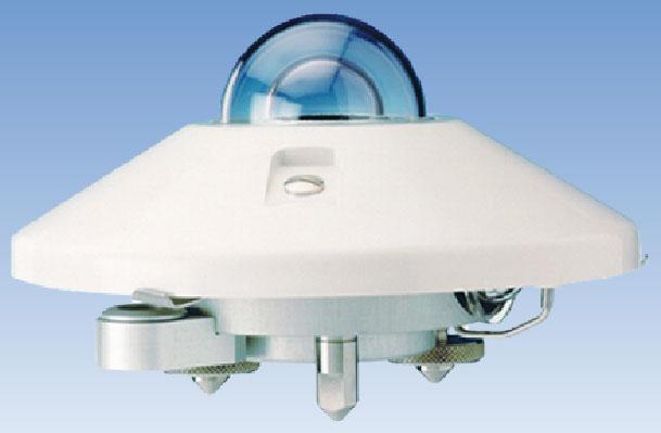
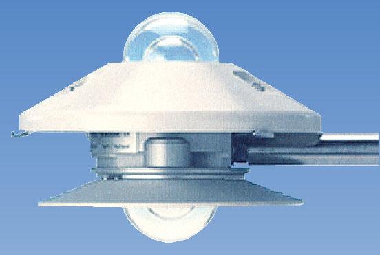
6 GENERAL INFORMATION 1. GENERAL INFORMATION 1.1 INTRODUCTION The pyranometer CM 6B is designed for measuring the irradiance (radiantflux, Watt/m 2 ) on a plane surface, which results from the direct solar radiation and from the diffuse radiation incident from the hemisphere above. Because the CM 6B exhibits no tilt dependence it can measure solar radiation on surfaces inclined as well. In the inverted position reflected solar radiation can be measured. The albedometer CM 7B is based on two CM 6B sensors and is suitable for the measurement of net global radiation and/or albedo over surfaces of different nature (see chapter 5 for installation). For measuring the diffuse component of solar radiation only, the direct solar component can be shielded semi-automatically from the pyranometer by the Kipp & Zonen shadow ring CM 121, and fully automatically by the 2AP tracker with shading system. The CM 6B pyranometer complies with the specifications for 'first class, which is second to secondary standard, as published in the 'Guide to meteorological Instruments and Methods of Observation', Fifth edition, 1983, of the World Meteorological Organization (WMO) - Geneva - Switzerland, and ISO 9060 of the Internaional Standard Organisation. The WMO classification list is adopted, improved and extended by the International Standard Organization ISO and published as ISO This standard is one of a series of standards specifying methods and instruments for the measurement of solar radiation. In this manual the specifications of accuracy are listed according the ISO 9060, in which the CM 6B is classified as a first class instrument. 5
7 GENERAL INFORMATION 1.2 PHYSICAL PRINCIPLES The pyranometer CM 6B is provided with a thermal detector. This type of detector responds to the total power absorbed and theoretically it is non-selective as to the spectral distribution of the radiation. This implies that the naked thermal detector is also sensitive to long wave infrared radiation (thermal radiation λ > 3000 nm) from the environment. (e.g. the inner dome) The radiant energy is absorbed by a black painted disk. The heat generated flows through a thermal resistance to the heat sink (the pyranometer body). The temperature difference across the thermal resistance of the disk is converted into a voltage. The rise of temperature is easily affected by wind, rain and thermal radiation losses to the environment ('cold' sky). Therefore the detector is shielded by two glass domes. Glass domes allow equal transmitting of the direct solar component for every position of the sun on the celestial sphere. The spectral range of the pyranometer is limited by the transmission of the glass. See figure 3. A desiccator in the body prevents dew on the inner side of the domes, which can cool down considerably, at clear windless nights. Construction details (See figure 1) The sensing element of the pyranometer CM 6B is a black painted ceramic (Al 2 O 3 ) disk. 100 thermocouples forming a thermopile are imprinted on it using thick film techniques. Only the border of the disk is in good thermal contact with the pyranometer body (heat sink), and along this border the 100 cold junctions are located. The 100 hot junctions are near the centre in a rotational symmetric arrangement. This fact plus a proper levelling of the sensor related to the spirit level results in a low azimuth error. When the pyranometer is illuminated, the absorbed radiation results in a radial heat flow to the border of the disk. The temperature in the centre of the disk will rise due to its thermal resistance. The thermal resistance of the Al 2 O 3 substrate is relatively low. E.g. an irradiance of 1000 W/m 2 results in a rise of centre temperature of 3 C only and a voltage of 4-6 mv. Natural convection 6
8 GENERAL INFORMATION inside the inner dome due to this temperature difference appeared to be small and when tilting a pyranometer CM 6B, no change of sensitivity is observed Zero offsets The following definition of zero offsets is used: When the sensor does not absorb radiation with wavelengths in the spectral range of the instrument and there still is a signal, we call it zero offset. Two types of zero offset are distinguished. Zero offset type B This zero offset arises when the body (heat sink) temperature increases or decreases. This results in a temperature difference between cold junctions (connected to the heat sink) and the hot junctions due to the heat flow necessary to load or unload the sensor heat capacity. In the CM 6B there is principally no zero offset B because there is a second non-illuminated compensation element. See figure 1. Other heat flows in the sensing element e.g. due to rising or falling body temperature cause spurious voltage, sometimes called zero offsets. See Appendix II. To compensate for one of these offsets, a second non-illuminated element is installed, in which the same heat flow will arise. By anti-series arrangement of both elements the spurious voltage is cancelled out greatly. The white plastic screen reduces the body temperature variations due to solar radiation and (cold) rain showers. Zero offset type A This zero offset is present when the inner dome has another temperature than the cold junctions of the sensor. Practically this is always the case when there is a clear sky. Because of the low effective sky temperature (<0 C) the earth surface emits roughly 100 W/m 2 long wave infrared radiation upwards. The outer glass dome of a pyranometer also has this emission and is cooling down several degrees below air temperature (the emissivity of glass for the particular wavelength region is nearly 1). The emitted heat is attracted from the body (by conduction in the dome), from the air (by wind) and from the inner dome (through infrared radiation). The inner dome is cooling down too 7

9 GENERAL INFORMATION and will attract heat from the body by conduction and from the sensor by the net infrared radiation again. The latter heat flow is opposite to the heat flow from absorbed solar radiation and causes the well known zero depression at night of approximately -5 W/m 2. This negative zero offset is also present on a clear day, however, hidden in the solar radiation signal. Figure 1 Approximate construction of Kipp & Zonen pyranometer CM 6B. During indoor measurements with a solar simulator, the inner dome can become warmer than the pyranometer body due to net thermal radiation from the lamp housing. A positive zero offset A is the result. The zero offset A can be checked by placing a light and IR reflecting cap over the pyranometer. A thin aluminium foil cap covering only the dome seems to be the best solution. The response to solar radiation will decay with a time constant 1/e of 4s, but the dome temperature will go to equilibrium with a time constant of several minutes. So after one minute the remaining signal is the main part of the last zero offset A. Good ventilation of domes and body is the solution to decrease zero offset A. Kipp & Zonen advises CV 2 for optimal ventilation and suppression of zero offset type A. Using the CV 2 zero offset type A will be less than 3 W/m 2. 8
10 GENERAL INFORMATION SUMMARIZED: Zero offset is the result of lack of thermal equilibrium in the instrument. Upper values of zero offset in CM 6B Zero offset A: 15 W/m 2 response to 200 W/m 2 thermal radiation (ventilated domes) Zero offset B: < 4 W/m 2 response to 5 C/hr change of body temperature Spectral range and spectral selectivity Spectral selectivity is the product of spectral absorptance of the black coating (see figure 2) and spectral transmittance of the glass domes (see figure 3). Shifts in the solar spectrum, due to changes from clear to overcast sky, are mainly in the mid of the spectral range. No significant spectral selectivity errors have to be expected. E.g. at a sun's elevation of 30 (air mass 2) only 2% of the solar radiation has wavelengths below 335 nm and only 2% of the solar radiation has wavelengths above 2200 mm. 9
11 GENERAL INFORMATION Figure 2 Spectral reflectance of Carbon black coating as measured in a UV/VIS/NIR spectrophotometer with integrating sphere attachment. 10
12 GENERAL INFORMATION Figure 3 1. Relative spectral transmittance of two pyranometer domes. (Four surface reflections and index change with wavelength are taken into account). 2. Spectral distribution of solar radiation at sea level. Sun at zenith (Air mass 1) Directional error The directional response is an individual feature and depends on imperfections of the glass domes and angular reflection properties of the black paint. A typical polar diagram of combined cosine and azimuth response (= directional response) of the CM 6B is shown in figure 4. To make corrections on the direct solar radiation with this diagram, the position of the sun on the celestial sphere and the ratio direct/global radiation must be known. 11
13 GENERAL INFORMATION Figure 4 Polar diagram of directional response of pyranometer CM 6B expressed as the percentage deviation of the ideal proportionally to the cosine of the zenith angle. The zenith axis was perpendicular to the base of the pyranometer. Orientation: cable was pointing to North Temperature dependence For a given heat flow the sensitivity of the pyranometer is a function of the thermal conductivity of the substrate and of the thermo-electric power of the thermocouple material. These physical quantities show temperature dependency, and a thermistor is applied in the electric circuit to keep the sensitivity constant at least for temperatures between -10 C and + 40 C. See figure 9. 12
14 TECHNICAL DATA 2. TECHNICAL DATA 2.1 SPECIFICATIONS Technical data of single version CM 6B Performance Spectral range: nm (50% points) Sensitivity: between 9 and 15 µv/wm -2 Impedance: Ohm Response time: < 18 s (95% response) Non-linearity: < ± 1.2% (< 1000 W/m 2 ) Temperature dependence of sensitivity: < ± 2% (-10 0 C to C) Directional error: < ± 20 W/m 2 (beam 1000 W/m 2 ) Tilt error < ± 1% (beam 1000 W/m 2 ) Zero-offset due to FIR (Ventilated with CV 2) < 15 W/m 2 at 200 W/m 2 net thermal radiation Zero-offset due to temp. changes < 4 W/m 2 at 5 K/h temp. change Operating temperature C to C 13
15 TECHNICAL DATA Viewing angle: 2 π sr Irradiance: W/m 2 (max W/m 2 ) Non-stability: < ± 1% sensitivity change per year Spectral selectivity ± 2% (0,35 µm to 1,5 µm) The specified directional response includes (as relative errors): Cosine response: max. ± 1% deviation from ideal at 60 0 solar zenith angle in any azimuth direction. max. ± 3% deviation from ideal at 80 0 solar zenith angle in any azimuth direction. Construction Receiver paint: Carbon black Glass domes: Schott K5 optical glass 2 mm thick, 30 mm and 50 mm outer diameter Desiccant: Silica gel Spirit level: Sensitivity 0.5 (bubble half out of the ring) Coincide with base of the instrument. Detector surface and base are coplanar within 0.1 Materials: Anodised aluminium case, seawater proof quality. Stainless steel screws corrosion free mounted. Anodised aluminium levelling screws. White plastic screen, ASA/PC Drying cartridge, PMMA Weight: 850 g Cable length: 10 m Dimensions: W x H= 150 x 95 mm. (See figure 5) 14
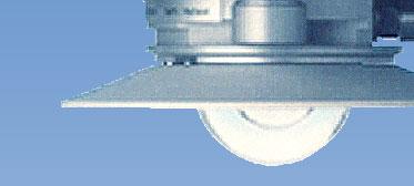
16 TECHNICAL DATA Technical data of Albedo version CM 7B The general technical data of the CM 6B pyranometer also apply to the albedometer CM 7B Sensors of equal sensitivity Conical lower screen, which prevents illumination of the lower glass dome at sunrise and sunset Impedance Depends on connection Weight, including rod 1.9 kg Cable length 10 m Dimensions See figure 6 15
17 TECHNICAL DATA Figure 5 Kipp & Zonen pyranometer CM 6B outline dimensions in mm. 16
18 TECHNICAL DATA Figure 6 Kipp & Zonen albedometer CM 7B outline dimensions in mm. 17
19 TECHNICAL DATA 2.2 ACCURACY Unfortunately the sensitivity is cross-correlated to a number of parameters as temperature, level of irradiance, vector of incidence, etc. The upper limiting values of the resulting sensitivity variations are listed in the specifications. It classifies the pyranometer CM 6B as a 'first class' according to the classification of the World Meteorological Organization. Normally, the supplied sensitivity figure is used to calculate the irradiances. If the conditions differ from calibration conditions, errors in the calculated irradiances must be expected. These errors can be reduced further if the actual sensitivity of the pyranometer is used by the conversion of voltage to irradiance. The actual sensitivity can be calculated when it is a well-known function of simply measured parameters (sometimes called transfer function or sensitivity function). This is especially convenient in connection with a programmable data acquisition system. For the CM 6B the effect of each parameter on the sensitivity can be shown separately, because the parameters show less interaction. The non-linearity error, the sensitivity variation with irradiance, is equal for any given CM 6B. See figure 7. 18
20 TECHNICAL DATA Figure 7 Non-linearity (sensitivity variation with irradiance) of Kipp & Zonen pyranometer CM 6B. The temperature dependence of the sensitivity is an individual function. For a given CM 6B the curve is somewhere in the shaded region of figure 8. Figure 8 The curve of relative sensitivity variation with instrument temperature of a pyranometer CM 6B is in the shaded region. A typical curve is drawn. 19
21 TECHNICAL DATA The directional error is the summation of the azimuth and zenith error and is commonly given in W/m 2. Figure 9 shows the maximum relative zenith error in any azimuth direction for the CM 6B. Figure 9 Relative directional error 20
22 INSTALLATION 3. INSTALLATION reading the installation instructions before installation is recommended. 3.1 DELIVERY Check the contents of the shipment for completeness (see below) and note whether any damage has occurred during transport. If there is damage, a claim should be filed with the carrier immediately. In this case, and also if the contents are incomplete, your dealer should be notified in order to facilitate the repair or replacement of the instrument. The CM 6B pyranometer delivery will include the following items: 1. CM 6B pyranometer 2. White sun screen 3. 2 x Mounting bolts + nuts + washers (M5 x 80) 4. 2 x nylon insulators 5. Calibration certificate 6. Temperature dependency data Unpacking Keep the original packaging for later shipments! Although all sensors are weatherproof and suitable for rough ambient conditions, they do partially consist of delicate mechanical parts. For this type of equipment, keep the original shipment packaging to safely transport the equipment to the measurement site. 21
23 INSTALLATION 3.2 MECHANICAL INSTALLATION The mechanical installation of the pyranometer depends upon the measuring purpose. Different measuring methods will be explained in the next paragraphs Installation for measurement of global radiation The following steps must be carefully taken for an optimal performance of the instrument: 1. Location Ideally the site for the pyranometer should be free from any obstructions above the plane of the sensing element, and at the same time the pyranometer should be readily accessible to clean the outer dome and inspect the dessicator. If this is not possible, the site should be chosen in such a way that any obstruction over the azimuth range between earliest sunrise and latest sunset should have an elevation not exceeding 5 (The apparent sun diameter is 0.5 ). This is important for an accurate measurement of the direct solar radiation. The diffuse (solar) radiation is less influenced by obstructions near the horizon. For instance, an obstruction with an elevation of 5 over the whole azimuth range of 360 decreases the downward diffuse solar radiation by only 0.8%. It is evident that the pyranometer should be located in such a way that a shadow will not be cast on it at any time (for example, by masts or exhaust pipes). Note that hot (over 100 degrees centigrade) exhausted gas will produce radiation in the spectral range of the CM 6B Pyranometer. The pyranometer should be distant from light-coloured walls or other objects likely to reflect sunlight onto it. In principle no special orientation of the instrument is required. 22
24 INSTALLATION The World Meteorological Organisation recommends that the emerging leads are pointed to the nearest pole, to minimise heating of the electrical connections. However, if a polar diagram of the combined azimuth and cosine response is available, the pyranometer may be orientated so that the solar path lies in the low error region. 2. Mounting The CM 6B pyranometer is provided with two holes for 5 mm bolts. Two stainless steel bolts and two nylon rings are provided. The pyranometer should first be secured lightly with the bolts to a mounting stand or platform (Shown in figure 10). Note: After reinstallation and recalibration the nylon insulators must be replaced with new ones to prevent corrosion. The mounting stand temperature can vary over a wider range than the air temperature. Temperature fluctuations of the pyranometer body can produce offset signals. It is recommended to isolate the pyranometer thermally from the mounting stand, e.g. by placing it on its levelling screws. But keep an electrical contact with earth to conduct away currents in the cable shield induced by lightning. Screw M5x80 Nylon insulator Washer M5 Nut M5 Figure 10 Mounting the pyranometer. 23
25 INSTALLATION 3. Levelling Accurate measurement of the global radiation requires proper levelling of the thermopile surface. Level the instrument by turning the levelling screws to bring the bubble of the spirit level within the marked ring. For easy levelling first use the screw nearest to the spirit level. When the CM 6B is placed horizontally using the spirit level, or when it is mounted with its base on a horizontal plane, the thermopile is horizontal within This causes a maximum azimuthal variation of + or 0.5% at a solar elevation of 10. By radiometrically levelling, the pyranometer can be placed more accurately horizontal (See Appendix II). Finally, the pyranometer should be secured tight with the two stainless steel bolts. Ensure that the pyranometer maintains the correct levelled position! Installation for measurement of solar radiation on inclined surfaces See also 'installation for measurement of global radiation'. It is advised to pre-adjust the levelling screws on a horizontal surface for easy orientation of the instrument parallel to the inclined surface. Because the temperature of the mounting stand is expected to rise considerably (more than 10 C above air temperature), the body must be thermally isolated by the levelling screws from the stand. This will promote a thermal equilibrium between domes and body and decrease zero offset signals. The CM 6B pyranometer shows no significant tilt effect up to irradiances of 1000 W/m 2. 24
26 INSTALLATION Installation for measurement of reflected global radiation In the inverted position the pyranometer measures reflected global radiation. According to the WMO the height should be 1-2 m above a surface covered by short cut grass. The mounting device should not interfere too much with the field of view of the instrument. A construction as in figure 11 is suitable. The upper screen prevents excessive heating of the pyranometer body by the solar radiation and, if large enough, it keeps the lower screen free of precipitation. The lower screen prevents direct illumination of the domes by the sun at sunrise and sunset. Offset signals generated in the pyranometer by thermal effects (see paragraph 1.2.1) are a factor of 5 more significant in the measurement of the reflected radiation due to the lower irradiance level. The mast in the construction of figure 11 intercepts a fraction D/2 π sr. of the radiation coming from the ground. In the most unfavourable situation (sun at zenith) the pyranometer shadow decreases the signal by a factor R 2 /H 2. A rule of thumb is: A black shadow with radius = 0.1 H on the field below decreases the signal 1%. Secondly 99% of the signal comes from an area with radius 10 H. Figure 11 Arrangement to measure reflected global radiation 25
27 INSTALLATION Installation for measurement of diffuse radiation For measuring sky radiation, the direct solar radiation is best intercepted by a small disk or sphere. The shadow of the disk must cover the pyranometer domes completely. However, to follow the sun's apparent motion, a power-driven tracking device is necessary. This can be done with the 2AP tracker, designed to track the sun under all weather conditions. More information about the combination of CM 6B and tracker is given in the 2AP tracker manual. Figure 12 2AP tracker with pyranometer Alternatively the use of a shadow ring is possible, however less accurate. The shadow ring intercepts the direct solar radiation some days without readjustment, but also a proportion of the diffuse sky radiation. Therefore corrections for this to the recorded data are necessary. Kipp & Zonen supplies a universal shadow ring CM 121 for all latitudes. In the CM 121 manual, installation instructions and correction factors are given Installation for measurement of Albedo The lower sensor of the albedometer construction, the pyranometer in the inverted position, measures the reflected solar radiation. According to the WMO the height should be 1-2 meters above a surface covered by short cut grass. The mounting device should not interfere too much with the field of view of the instrument. A construction as in figure 13 is suitable. The upper screen prevents excessive heating of the pyranometer body by solar radiation. 26
28 INSTALLATION The special screen for the lower CM 6B prevents direct illumination of the domes by the sun at sunrise and sunset. Kipp & Zonen can also supply this screen for a separate CM 6B (see chapter 9 for the part number). Offset signals generated in the Pyranometer by thermal effects (see paragraph 1.2.1) are a factor of 5 more significant in the measure-ment of the reflected radiation due to the lower irradiance level. The mast in the construction of figure 12 intercepts a fraction D / 2 πs of the radiation coming from the ground. In the most unfavourable situation (sun at zenith) the pyranometer shadow decreases the signal by a factor R 2 / H 2. Figure 13 Albedo measurement construction Underwater use The CM 6B pyranometer is in principle watertight. However, the hemispherical air-cavity under the dome(s) acts as a negative lens. The parallel beam of direct solar radiation becomes divergent after the passage of the outer dome. Consequently the intensity at the sensor is lower than outside the pyranometer. The sensitivity figure is not valid in this case but must be derived empirically. 27
29 INSTALLATION 3.3 ELECTRICAL CONNECTION The CM 6B is provided with a 10 m cable with three leads and a shield covered with a black sleeve. The colour code is: red = plus blue = minus white = case The shield is isolated from the case, so no shield-current can exist. Shield and white lead may be connected to the same ground at the readout equipment. The cable must be firmly secured to minimise spurious response during stormy weather (pressing the standard cable produces voltage spikes, a tribo electric effect and capacitance effect). Kipp & Zonen pyranometer cables are of low noise type, however take care that the terminals '+' and '-' at a connection box have the same temperature, to prevent thermal EMF's. A box or connector with metal outer case is advised. Looking at the circuit diagram of figure 14, it is clear that the impedance of the readout equipment is loading the thermistor circuit and the thermopiles. It can increase the temperature dependency of the pyranometer. The sensitivity is affected more than 1% when the load resistance is under 150 kω. For this reason we recommend the use of readout equipment with input impedance s of 1 MΩ or more such as potentiometric recorders, digital voltmeters, etc. The solar integrators and chart recorders from Kipp & Zonen meet these requirements. Long cables may be used, but the cable resistance must be smaller than 0.1% of the impedance of the readout equipment. Kipp & Zonen supplies shielded low-noise extension cable up to lengths of 200 m. This extra length can be supplied fitted to the pyranometer when ordered, or can be coupled by waterproof connectors to the CM 6B cable. The lead resistance is 8 Ohm/100 m. 28
30 INSTALLATION It is evident that application of attenuator circuits to modify the calibration factor is not recommended because the temperature response will also be affected. However, recorders with a variable voltage range can be set so that the result can be read directly in W/m 2. Figure 14 Circuit diagram of the CM 6B pyranometer and connection to readout equipment. When an optional temperature sensor is built in, the following colour code is used: PT 100 Yellow: Pt 100(combined with brown) Brown: Pt 100 (combined with yellow) Green: Pt 100 (combined with grey) Grey: Pt 100 (combined with green) Thermistor Yellow Green 29
31 INSTALLATION A considerable input bias current of the readout equipment can produce a voltage of several microvolts across the impedance of the pyranometer. The correct measured zero signal can be verified with a resistance replacing the pyranometer impedance at the input terminals. The pyranometer can also be connected to a computer or data acquisition system. A low voltage analogue input module with A to D converter must be available then. The span and resolution of the A to D converter in the module must allow a system sensitivity of about 1 bit per W/m 2. More resolution is not necessary during outdoors solar radiation measurements, because pyranometers exhibit offsets up to + or - 2 W/m 2 due to lack of thermal equilibrium. A surge arrester is installed to conduct induced lightning currents to the case. It is recommended to ground the case for this reason. The surge arrester is noble gas filled, has infinite impedance and recovers after breakdown. Breakdown voltage is 90 V. Peak pulse current is 10 ka. For amplification of the pyranometer signal Kipp & Zonen recommends the CT 24 amplifier, available from Kipp & Zonen. This amplifier will convert the microvolt output from the pyranometer into a standard 4 20 ma signal. Voltage output and amplification adjustment to the pyranometer calibration factor are also possible. 30
32 INSTALLATION Electrical connection CM 7B The CM 7B is provided with a 10 m cable with shield and five leads. The colour code is: red : + upper sensor blue : - upper sensor green : + lower sensor yellow : - lower sensor white : case There are two modes of operating an albedometer: - With the sensors connected in anti-series, the net global radiation is measured. - When the outputs are recorded separately, the Albedo can be calculated by dividing reflected by global radiation. 31
33 INSTALLATION Figure 15 Circuit diagram of Kipp & Zonen Albedometer CM 7B and connection to readout equipment 32
34 OPERATION 4. OPERATION After completing the installation the pyranometer will be ready for operation. The irradiance value (E Solar ) can be simply computed by dividing the output signal (U emf ) of the pyranometer by its sensitivity (S ensitivity ) formula 1, or by multiplication of the voltage value with the reciprocal of the sensitivity. (Often called the calibration factor). For calculation of the solar irradiance the following formula must be applied: E = Solar U S emf ensitivity (formula 1) E Solar = Global radiation [W/m 2 ] U emf = Output of pyranometer [µv] S ensitivity = Sensitivity of pyranometer [µv/w/m 2 ] To be certain that the quality of the data is of a high standard, care must be taken with daily maintenance of the pyranometer. Once a voltage measurement is taken, nothing can be done to retrospectively improve the quality of that measurement. Many years of experience has shown that pyranometer performance can be improved concerning the zero offset type A by using a proper ventilation system. The Kipp & Zonen CV 2 ventilation unit is recommended as an optimal combination to minimise or eliminate this remaining error. 33
35 34 OPERATION
36 MAINTENANCE 5. MAINTENANCE Once installed the pyranometer needs little maintenance. The outer dome must be cleaned and inspected regularly, e.g. every morning. On clear windless nights the outer dome temperature of horizontally placed pyranometers will decrease, even to the dew point temperature of the air, due to IR radiation exchange with the cold sky. (The effective sky temperature can be 30 C lower than the ground temperature). In that case dew, glazed frost or hoar frost can be precipitated on the top of the outer dome and can stay there for several hours in the morning. An ice cap on the dome is a strong diffuser and increases the pyranometer signal drastically up to 50% in the first hours after sunrise. Hoar frost disappears due to solar radiation during the morning, but should be wiped of as soon as possible manually. Another daily check is to ensure that the instrument is level and that there is no condensation inside the dome. If there is condensation the silica gel must be replaced, even when the colour is still blue. Apparently the location requires very fresh silica gel and a low dew point inside. It is normal in humid areas to replace the desiccant twice a year. The exchange interval is affected by humidity, change in air pressure and the amount of temperature changes. When the blue silica gel in the drying cartridge is turned pink (normally after several months), it must be replaced by active material. Pink silica gel can be activated again in an oven at 130 C within several hours. Apart from that it is good to visit the pyranometer (or any other sensor) regularly to check its condition. (desiccant, dirt on dome, levelling of instrument and condition of cabling) Some tips to check when changing the desiccant: - Make sure the surfaces of the pyranometer and the cartridge that touch the rubber ring are clean (corrosion can do a lot of harm here and dirt, in combination with water, can cause this) 35
37 MAINTENANCE - The rubber ring is normally coated with a silicon grease (Vaseline will also do) to make the seal even better. If the rubber ring looks dry apply some grease to it. - Check that the metal spring that retains the drying cartridge applies enough force. It is normal that you have to use two hands to open and close it. It is very difficult to make the pyranometers hermetically sealed. The only way to do this properly is to put the inside of the instrument under pressure. (> 1.0 Bar), but this has to be checked at yearly intervals. So, due to pressure differences inside and outside the instrument there will always be some exchange of (humid) air. In some networks, the exposed dome of the pyranometer is ventilated continuously by a blower to keep the dome above dew point temperature. The need for heating strongly depends upon local climatological circumstances. Generally heating is advised during cold seasons when frost and dew can be expected. The ventilation also decreases the sensitivity to thermal radiation (zero offset type A) by a factor of 2 or more. The Kipp & Zonen CV 2 ventilation unit is specially designed for accurate unattended operation under most weather conditions. 36
38 CALIBRATION 6. CALIBRATION 6.1 INITIAL CALIBRATION The ideal pyranometer should always have a constant ratio of voltage output to irradiance level (outside the instrument in the plane of the sensing element). This ratio is called sensitivity (S ensitivity ) or responsivity. The sensitivity figure of a particular pyranometer is unique. It is determined in the manufacturer's laboratory by comparison against a standard pyranometer. The standard pyranometer is calibrated outdoors regularly at the World Radiation Centre (Davos, Switzerland). The spectral content of the laboratory lamp differs from the outdoors solar spectrum at the Radiation Centre of course. However, this has no consequences for the transfer of calibration, because standard and unknown pyranometer have the same black coating and quartz glass domes. The supplied sensitivity figure is valid for the following conditions: An ambient temperature of 20 C. For a horizontal pyranometer as well as for a tilted pyranometer. Normal incident radiation of 500 W/m 2. Spectral content as clear sky solar radiation. 6.2 RECALIBRATION Pyranometer sensitivity changes with time and with exposure to radiation. Periodic calibration (at least every two years) is advised. Accurate calibrations can be done outdoors under clear conditions by reference to a standard Pyrheliometer. Many National Weather Services have calibration facilities. Their standard Pyrheliometer is compared with the World Radiometric Reference (maintained at Davos, Switzerland) embodied by several absolute Pyrheliometer (black body cavity type). 37
39 CALIBRATION The comparisons are in-doors or at one of the regional Radiation Centres, see Appendix III. These institutes sometimes offer calibration facilities. There are several procedures for transferring calibration from a narrow field of view instrument (Pyrheliometer) to a wide field of view instrument (pyranometer). E.g. the direct component of the solar radiation is eliminated temporarily from the pyranometer by shading the whole outer dome of the instrument with a disk. There is however no thermal equilibrium with this method and some pyranometer models show zero-offset drift. There is another procedure, during which the unknown pyranometer remains in its normal operating condition. This 'component' method involves measuring the direct component with a Pyrheliometer and the diffuse component with a disk shaded pyranometer. As, during a clear day, the diffuse radiance is only about 10% of the global radiation, the sensitivity of the second pyranometer does not need to be known very accurately. Both procedures are suitable to obtain a working standard pyranometer. The latter is extensively described in International standard ISO Transfer from the working standard pyranometer to other pyranometers can be done in sunlight. The pyranometers must be mounted side by side so that each views the same sky dome. It is desirable to integrate, or average, the outputs over a period of time and then compute the calibration constants on the basis of these averages. This reduces the errors due to changing parameters during the day. Transfer from another pyranometer in the laboratory is only possible when both pyranometers are of the same type and have the same glass domes and optical coatings. Kipp & Zonen can recalibrate pyranometers according to this method for a charge. A summary of calibration methods is also found in the WMO guide of
40 CALIBRATION To send a pyranometer back for recalibration the use of the recalibration form in appendix V is strongly recommended. 6.3 CALIBRATION PROCEDURE AT KIPP & ZONEN The facility The indoor calibration procedure is based on a side-by-side comparison with a reference pyranometer under an artificial sun fed by an AC voltage stabiliser. It embodies a 150 W Metal-Halide high-pressure gas discharge lamp. Behind the lamp is a reflector with a diameter of 16.2 cm. The reflector is 110 cm above the pyranometers producing a vertical beam. The irradiance at the pyranometers is approximately 500 W/m² To minimise stray light from the walls and the operator, the light is limited to a small cone around the two pyranometers. The unknown pyranometer 'a' and the standard pyranometer 'b' are placed side by side on a small table. The table can rotate to interchange the positions (1 and 2) of the pyranometers. The lamp is centred on the rotating axis of this table. Actually there is no normal incidence of the radiation, but the angle of incidence is the same for both pyranometers (3 ) so this cannot give rise to errors. The two pyranometers are not levelled with the screws, but placed on their bases. The effect of a small tilt is almost zero (Compare cos. 3 = and cos. 4 = ) Procedure After illuminating for 30 s, the output voltages of both pyranometers are integrated over 30 s with a solar integrator. Next, both pyranometers are covered by a blackened 'hat'. After 30 s the zero offset signal of both pyranometers is integrated again. The problem of the zero offset is described below. This zero offset has to be subtracted to obtain the response due to illumination. So we get response A and B respectively. 39
41 CALIBRATION The irradiance at position 1 (pyranometer 'a') may be slightly different from that at position 2 (pyranometer 'b') due to asymmetry in the lamp optics etc. Therefore the pyranometers are interchanged and the whole procedure is repeated. We get another pair of values: A' and B' Calculation The sensitivity of the unknown pyranometer is calculated with the formula 2: S a = A + A' B + B' s b (formula 2) S b = Sensitivity of the standard pyranometer at 20 C. A = Output of pyranometer at position 1 A = Output of pyranometer at position 2 B = Output of standard pyranometer at position 2 B = Output of standard pyranometer at position 1 = Sensitivity of the pyranometer at 20 C. S a Output = (mean value at 100% response minus zero offset signal) Zero offset The lamp housing and diaphragms are emitting long wave infrared radiation, which heats up the outer glass dome and also, indirectly, the inner one. When the pyranometers are shaded, there still remains a small signal up to + 20 µv due to long wave infrared radiation from the inner dome to the sensor. This zero offset is decreasing with a time constant (1/e) of several minutes. A zero offset was also embodied in the response due to illumination. To correct for this unwanted response, the zero offset read after 60 s shading is subtracted. 40
42 CALIBRATION Traceability to World Radiometric Reference Working standard pyranometers are maintained at Kipp & Zonen. Each standard pyranometer is characterised. Linearity, temperature dependence curve and directional response are well known. The working standard pyranometers are calibrated each year at the World Radiation Centre in Davos, Switzerland, periodically according to the component method. An extended calibration certificate, mentioning the Davos procedure, is available. 41
43 42 CALIBRATION
44 FREQUENTLY ASKED QUESTIONS 7. FREQUENTLY ASKED QUESTIONS (FAQ s) The most frequently asked questions are listed below. For an update refer to the Kipp & Zonen web page: 1. Negative output during night time measurements? This error is related to the zero offset type A. Normally this zero offset is present when the inner dome has a different temperature from the cold junctions of the sensor. Practically this is always the case when there is a clear sky. Because of the low effective sky temperature (<0 C) the earth surface emits roughly 100 W/m 2 long wave infrared radiation upwards. The outer glass dome of a pyranometer also has this emission and is cooling down several degrees below air temperature (the emissivity of glass for the particular wavelength region is nearly 1). The emitted heat is attracted from the body (by conduction in the dome), from the air (by wind) and from the inner dome (through infrared radiation). The inner dome is cooling down too and will attract heat from the body by conduction and from the sensor by the net infrared radiation. The latter heat flow is opposite to the heat flow from absorbed solar radiation and causes the well known zero depression at night. This negative zero offset is also present on a clear day, however, hidden in the solar radiation signal. Zero offset type A can be checked by placing a light and IR reflecting cap over the pyranometer. The state of the art is to use a thin aluminium foil cup covering only the outer dome. With this configuration only the fluxes (short wave and long wave) to the outer dome are blocked. Other heat fluxes from wind etc. remain undisturbed. The response to solar radiation will decay with a time constant (1/e) of 4 s, but the dome temperature will go to equilibrium with a time constant of several minutes. So after half a minute the remaining signal represents mainly zero offset type A. 43
45 FREQUENTLY ASKED QUESTIONS Good ventilation of domes and body is the solution to reducing zero offsets even further. Kipp & Zonen advises the CV 2 for optimal ventilation and suppression of zero offset type A. Using the CV 2 zero offset type A will be less than 3 W/m Maximum and minimum irradiation quantities? Due to possible reflection from clouds the global irradiance at sea level can rise above the extraterrestrial irradiance of 1367 W/m 2 at the top of the atmosphere. Values up to 1500 W/m 2 have been reported. Because the clouds move, this irradiance value mostly appears as short events of some minutes duration. 3. What is the primary entry point for humidity? The desiccant cartridge and cable glands have equal chances to transport some moisture but also the silicon glue of the domes is not fully watertight. However, normally the cable gland is never touched while the cartridge is removed frequently. So when no care is taken (see above) one can easily make the desiccant cartridge the primary entry point. Note. Water transport through the cable is also possible when the open end of the cable and the connected device are in a humid environment 44
46 TROUBLE SHOOTING 8. TROUBLE SHOOTING The following contains a procedure for checking the instrument in case it appears that it does not function as it should. Trouble shooting: Output signal fails or shows improbable results: Check the wires, whether they are proper connected to the readout equipment. Check the instrument location. Are there any obstructions that cast a shadow on the instrument by blocking the direct sun during some part of the day. Check the window, it should be clear. If water is deposited on the inside, please change the desiccant. If too much water is deposited the instrument should be dried internally. Check instrument impedance ( Ohm) Check data logger or integrator offset by connecting a dummy load ( Ohm resistor). This should give a zero reading. If water or ice is deposited to the outside, clean the outside. Probably water droplets will evaporate in less than one hour. Any visible damage or malfunction should be reported to your dealer, who will suggest appropriate action. 45
47 46 TROUBLE SHOOTING
48 PARTNUMBERS / SPARE PARTS / OPTIONS 9. PART NUMBERS / SPARE PARTS / OPTIONS Description Part no. Outer glass dome 50 mm with metal ring Rubber ring for outer glass dome of CM 6B Screen (plastic) Levelling screw (2 required per pyranometer) Fixed foot Replacement drying cartridge Clamp-Spring Drying cartridge (without cover) Cover for cartridge Rubber ring Measuring/compensating cell in housing covered by inner glass dome Silica gel (1 kg) container
49 PARTNUMBERS / SPARE PARTS / OPTIONS Description Part no. Mounting plate for 4 unventilated sensors (2 upper and 2 lower)
50 APPENDIX I APPENDIX I CLASSIFICATION ACCORDING TO WMO GUIDE 1996 Characteristics CM 6B High quality Good quality Moderate quality ISO 9060 classification Secondary standard First class Second class Response time (95 percent response) 5 s < 15 s < 30 s < 60 s Zero offset: (a) Response to 200 W/m 2 net thermal radiation (ventilated) (b) Response 5 K/h change in ambient temperature Resolution (smallest detectable change) Stability (change per year, percentage of full scale) Directional response of beam radiation (The range of errors caused by assuming that the normal incidence responsivity is valid for all directions when measuring, from any direction, a beam radiation whose normal incidence irradiance is 1000 W/m 2 ) Temperature response (percentage of maximum due to any change of ambient temperature within an interval of 50 K) Non-linearity (percentage deviation from the responsivity at 500 W/m 2 due to any change of irradiance within the range 100 to 1000 W/m 2 ) Spectral sensitivity (percentage of deviation of the product of spectral absorptance and spectral transmittance from the corresponding mean within the range of 0.3 to 3 µm) Tilt response (percentage deviation from the responsivity at 0 tilt, horizontal, due to change in tilt from 0 to 90 at 1000 W/m 2 irradiance) <± 3 W/m 2 (with CV 2) <± 1 W/m 2 <± 7 W/m 2 <± 2 W/m 2 <± 15 W/m 2 <± 4 W/m 2 <± 30 W/m 2 <± 8 W/m 2 <± 1 W/m 2 ± 1 W/m 2 ± 5 W/m 2 ± 10 W/m 2 < 0.5 ± 0.8 ± 1.5 ± 3.0 <± 5 W/m 2 <± 10 W/m 2 <± 20 W/m 2 <± 30 W/m 2 <± C C <± 2 <± 4 <± 8 <± 0.2 <± 0.5 <± 1 <± 3 <± 2 <± 2 <± 5 <± 10 <± 0.25 <± 0.5 <± 2 <± 5 Achievable uncertainty, 95 percent confidence level Hourly totals Daily totals 2 % 1 % 3% 2% 8% 5% 20% 10% 49
51 50 APPENDIX I
52 APPENDIX II APPENDIX II RADIOMETRIC LEVELLING This must be done in the laboratory by mounting the instrument on a stand that can be rotated around an axis that is accurately vertical and passes through the centre of the receiving surface. The instrument then is illuminated by a lamp so that radiation falls at an elevation of approximately 15 to the horizontal; the lamp should be fed by a constant voltage supply. The output from the radiation instrument is measured at various azimuths and the level of the instrument adjusted independently of that of the rotating stand until the least possible variation is obtained as the instrument is rotated around the vertical axis. Once this has been done, the spirit level is marked so that the correct level can be found back outdoors. 51
53 52 APPENDIX II
54 APPENDIX III APPENDIX III LIST OF WORLD AND REGIONAL RADIATION CENTRES World Radiation Centres Davos (Switzerland) St. Petersburg (Russia) Regional Radiation Centres Region I Africa: Cairo (Egypt) Khartoum (Sudan) Kinshasa (Zaire) Lagos (Nigeria) Tamanrasset (Algeria) Tunis (Tunisia) Region II Asia: Poona (India) Tokyo (Japan) Region III South America: Buenos Aires (Argentina) Region IV North and Central America: Toronto (Canada) Washington (U.S.A.) Region V Southwest Pacific: Aspendale (Australia) Region VI Europe: Bracknell (United Kingdom) Budapest (Hungary) Davos (Switzerland) St. Petersburg (Russia) Norrköping (Sweden) Trappes/Carpentras (France) Uccle (Belgium) Potsdam (Germany) 53
Model 3024 Albedometer. User s Manual 1165 NATIONAL DRIVE SACRAMENTO, CALIFORNIA WWW. ALLWEATHERINC. COM
 Model 3024 Albedometer User s Manual 1165 NATIONAL DRIVE SACRAMENTO, CALIFORNIA 95834 WWW. ALLWEATHERINC. COM TABLE OF CONTENTS INTRODUCTION... 1 THEORY OF OPERATION... 2 General Description... 2 Accuracy...
Model 3016 Secondary Standard Pyranometer. User s Manual 1165 NATIONAL DRIVE SACRAMENTO, CALIFORNIA WWW. ALLWEATHERINC. COM
 Model 301 Secondary Standard Pyranometer User s Manual 115 NATIONAL DRIVE SACRAMENTO, CALIFORNIA 95834 WWW. ALLWEATHERINC. COM Secondary 3 Standard 0 1Pyranometer TABLE OF CONTENTS INTRODUCTION... 1 THEORY
Kipp Zonen & INSTRUCTION MANUAL PRECISION PYRANOMETER
 Kipp Zonen & INSTRUCTION MANUAL 22 PRECISION PYRANOMETER 0351 200 IMPORTANT USER INFORMATION Reading this entire manual is recommended for full understanding of the use of this product. The exclamation
LP PYRA Installation and Mounting of the Pyranometer for the Measurement of Global Radiation:
 CENTRO DI TARATURA SIT N 124 TEL. +39.049.8977150 r.a. FAX +39.049.635596 1 Introduction LP PYRA 03 The LP PYRA 03 pyranometer measures the irradiance on a plane surface (Watt/ m 2 ). Measured irradiance
LP NET. 1 About LP NET. 2 Working Principle. TEL r.a. FAX
 CENTRO DI TARATURA SIT N 124 MEASURING INSTRUMENTS REGULATORS STRUMENTI DI MISURA REGOLATORI TEL. +39.049.8977150 r.a. FAX +39.049.635596 LP NET 1 About LP NET LP NET net radiometer is designed to measure
LP PYRA 10 AV. 1 Introduction. 2 Working Principle
 LP PYRA 13 1 Introduction The LP PYRA 13 pyranometer measures the irradiance on a plane surface (Watt/ m 2 ). Thanks to the shadow-ring, the LP PYRA 13 measure the diffuse solar radiation eliminating the
COMPARISON OF GUNN BELLANI RADIOMETER DATA WITH GLOBAL SOLAR RADIATION SENSOR (PYRANOMETER CM6B) Author. Mungai Peter N.
 Author. Mungai Peter N.") COMPARISON OF GUNN BELLANI RADIOMETER DATA WITH GLOBAL SOLAR RADIATION SENSOR (PYRANOMETER CM6B) Author Mungai Peter N. Kenya Meteorological Department. P.O.Box 30259-00100 GPO Nairobi, Kenya. Phone 254-2-3867880
COMPARISON OF GUNN BELLANI RADIOMETER DATA WITH GLOBAL SOLAR RADIATION SENSOR (PYRANOMETER CM6B) Author Mungai Peter N. Kenya Meteorological Department. P.O.Box 30259-00100 GPO Nairobi, Kenya. Phone 254-2-3867880
SP-LITE SILICON PYRANOMETER INSTRUCTION MANUAL
 SP-LITE SILICON PYRANOMETER INSTRUCTION MANUAL REVISION: 5/02 COPYRIGHT (c) 1998-2002 CAMPBELL SCIENTIFIC, INC. This is a blank page. Warranty and Assistance The SP-LITE SILICON PYRANOMETER is warranted
USER MANUAL DR-SERIES PYRHELIOMETERS
 Hukseflux Thermal Sensors USER MANUAL DR-SERIES PYRHELIOMETERS First class pyrheliometer DR01 Fast response first class pyrheliometer DR02 Compact fast response first class pyrheliometer DR03 Copyright
INSTRUCTION MANUAL PYRGEOMETER
 INSTRUCTION MANUAL PYRGEOMETER 0359 200 IMPORTANT USER INFORMATION IMPORTANT USER INFORMATION Reading this entire manual is recommended for full understanding of the use of this product. Should you have
SENSOR. Weather TRANSMITTERS
 Weather SENSOR TRANSMITTERS 4~20mA Environmental Monitoring Probe Sets Anemometer (Wind Speed) Wind Vane Light Energy Sensor (Pyranometer) Solar Radiation Shield Model THP-CL Humidity Sensor Temperature
Chapter 2 Available Solar Radiation
 Chapter 2 Available Solar Radiation DEFINITIONS Figure shows the primary radiation fluxes on a surface at or near the ground that are important in connection with solar thermal processes. DEFINITIONS It
CM3 PYRANOMETER INSTRUCTION MANUAL
 CM3 PYRANOMETER INSTRUCTION MANUAL REVISION: 10/02 COPYRIGHT (c) 1999-2002 CAMPBELL SCIENTIFIC, INC. This is a blank page. WARRANTY AND ASSISTANCE This equipment is warranted by CAMPBELL SCIENTIFIC (CANADA)
INSTRUCTION MANUAL. SP Lite2 Pyranometer. August Copyright 2017 Campbell Scientific (Canada) Corp.
 Corp.") INSTRUCTION MANUAL SP Lite2 Pyranometer August 2017 Copyright 2017 Campbell Scientific (Canada) Corp. WARRANTY AND ASSISTANCE This equipment is warranted by CAMPBELL SCIENTIFIC (CANADA) CORP. ("CSC")
INSTRUCTION MANUAL SP Lite2 Pyranometer August 2017 Copyright 2017 Campbell Scientific (Canada) Corp. WARRANTY AND ASSISTANCE This equipment is warranted by CAMPBELL SCIENTIFIC (CANADA) CORP. ("CSC")
Measurement method for the proficiency testing program
 APLAC T088 Appendix Measurement method for the proficiency testing program Introductions This measurement method is prepared for use by the APLAC Proficiency Testing Program Photometric measurement of
STATIC GAS MONITOR Type SGM/DEW Revision A of 20 aprile 2016
 APPLICATIONS Moisture monitoring of air or gas (SF6) Suitable for indoor or outdoor Industrial, medical or aerospace fields HIGHLIGHTS High voltage circuit breakers commonly used for distribution and transmission
Solar and Earth Radia.on
 Solar and Earth Radia.on Solar and Earth Radia.on Solar radia.on Any incoming radia.on measured at the earth s surface Earth radia.on The long- wave band of radia.on emi>ed by the earth What are the typical
Infrared Thermometer Calibration A Complete Guide
 Infrared Thermometer Calibration A Complete Guide Application note With proper setup and planning, infrared calibrations can be accurate. The steps outlined below should be followed to perform accurate
Infrared Temperature Calibration 101 Using the right tool means better work and more productivity
 Infrared Temperature Calibration 101 Using the right tool means better work and more productivity Application Note Infrared thermometers let you measure a target s surface temperature from a distance without
Amplified Pyranometer SP-212 & 215
 Amplified Pyranometer SP-212 & 215 Amplified Pyranometer Sensor This sensor is calibrated to measure total shortwave radiation. The evaporation of water from soil and the transpiration of water from plant
USER MANUAL HFP01 & HFP03
 Hukseflux Thermal Sensors USER MANUAL HFP01 & HFP03 Heat flux plate / heat flux sensor Copyright by Hukseflux manual v1721 www.hukseflux.com info@hukseflux.com Warning statements Putting more than 12 Volt
1.0 BACKGROUND 1.1 Surface Radiation
 1.0 BACKGROUND 1.1 Surface Radiation Meteorologists have utilized recent advances in computer speeds and atmospheric models to create increasingly accurate models of the environment. The computational
Characterizing the Performance of an Eppley Normal Incident Pyrheliometer
 Characterizing the Performance of an Eppley Normal Incident Pyrheliometer Frank Vignola Fuding Lin Department of Physics Department of Chemistry 1274-University of Oregon Eugene, OR 9743-1274 fev@uoregon.edu
Meteorological Service
 Meteorological Service The Meteorological Service in Oman was established in 1973. Oman joined ICAO in 1973 Oman joined WMO in 1975. Meteorological Service is under the framework of the Directorate General
Self-Testing Prevectron 2 Millenium Lightning Conductor Set-up and Installation Manual
 Self testing Prevectron 2 Millenium Lightning Conductor ENGLISH Self-Testing Prevectron 2 Millenium Lightning Conductor Set-up and Installation Manual S6.60T S4.50T S3.40T N.B. : Information and Specifications
WS-7047TWC Wireless 433 MHz Weather Station With Rainfall and Temperature. Instruction Manual
 WS-7047TWC Wireless 433 MHz Weather Station With Rainfall and Temperature Instruction Manual TABLE OF CONTENTS Topic Page Inventory of Contents 2 Additional Equipment 2 Quick Setup 3 Detailed Setup Guide
Winter Night. Thermos 6mm Outdoors # #
 February 26, 2016 By Gagnon, Stephan stephan@thermosrn.ca Thermos 3mm à 6mm vs Climaguard 80/70 Make-up Name Make-up Icon Transmittance Reflectance U-Value Visible (τ v %) (τ e %) Visible ρ v % out ρ v
CHAPTER CONTENTS. Page
 CHAPTER CONTENTS CHAPTER 7. MEASUREMENT OF RADIATION... 222 7.1 General... 222 7.1.1 Definitions... 222 7.1.2 Units and scales... 223 7.1.2.1 Units... 223 7.1.2.2 Standardization... 223 7.1.3 Meteorological
ISOCON-6. 24V AC or DC POWERED ISOLATING SIGNAL CONVERTER
 ISOCON-6 24V AC or DC POWERED ISOLATING SIGNAL CONVERTER Whilst every effort has been taken to ensure the accuracy of this document, we accept no responsibility for damage, injury, loss or expense resulting
Peltier Application Note
 Peltier Application Note Early 19th century scientists, Thomas Seebeck and Jean Peltier, first discovered the phenomena that are the basis for today s thermoelectric industry. Seebeck found that if you
Practical 1P4 Energy Levels and Band Gaps
 Practical 1P4 Energy Levels and Band Gaps What you should learn from this practical Science This practical illustrates some of the points from the lecture course on Elementary Quantum Mechanics and Bonding
Directions for use
 Directions for use 40070 40080 60050 70060 70076 80060 90060 900114 Fig. 1 Fig. 1A Fig. 2 Fig. 3 Fig. 4 Fig. 5 Fig. 6 Fig. 7 english ENGLISH DIRECTIONS FOR USE 1 Tripod Leg 2 Tripod Leg Adjusting Screw
Installation guide 862 MIT / MIR
 Installation guide 862 MIT / MIR in combination with: 864 MTT or 863 MRT or (dual) spot element November 2005 Part no. 4416.232_Rev3 Enraf BV PO Box 812 2600 AV Delft Netherlands Tel. : +31 15 2701 100
Latest generation testo air velocity & IAQ probes with cable handle. Instruction manual
 Latest generation testo air velocity & IAQ probes with cable handle Instruction manual Contents Contents 1 About this document... 5 2 Safety and disposal... 5 3 System description... 6 4 Description of
Practical 1P4 Energy Levels and Band Gaps
 Practical 1P4 Energy Levels and Band Gaps What you should learn from this practical Science This practical illustrates some of the points from the lecture course on Elementary Quantum Mechanics and Bonding
Today s Weather 24 Hour Forecaster
 1380 Today s Weather 24 Hour Forecaster Instruction Manual The Taylor 24 Hour Forecaster will provide you with actual current temperatures. Predict the weather conditions for the next 24 hours as well
Fischer Instruments Chrome and Black Wood Base Weather Station with Barometer, Hygrometer, Thermometer and Quartz Clock User Manual
 Fischer Instruments 1535-06 Chrome and Black Wood Base Weather Station with Barometer, Hygrometer, Thermometer and Quartz Clock User Manual Table of Contents 1. Introduction... 2 2. Care and Cleaning...
Operating Instructions for Digital Manometer. Model: MAN-SD
 Operating Instructions for Digital Manometer Model: MAN-SD 1. Contents 1. Contents...2 2. Note...3 3. Instrument Inspection...3 4. Regulation Use...4 5. Operating Principle...4 6. Mechanical Connection...5
Series tore word. Acknowledgements
 Series tore word p. xi Preface p. xiii Acknowledgements p. xv Disclaimer p. xvii Introduction p. 1 The instrumental age p. 2 Measurements and the climate record p. 2 Clouds and rainfall p. 3 Standardisation
NOVALYNX CORPORATION MODEL 110-WS-16BP BAROMETRIC PRESSURE SENSOR INSTRUCTION MANUAL
 NOVALYNX CORPORATION MODEL 110-WS-16BP BAROMETRIC PRESSURE SENSOR INSTRUCTION MANUAL REVISION DATE: OCT 2005 Receiving and Unpacking Carefully unpack all components and compare to the packing list. Notify
Technical Notes. Introduction. PCB (printed circuit board) Design. Issue 1 January 2010
 Design. Issue 1 January 2010") Technical Notes Introduction Thermal Management for LEDs Poor thermal management can lead to early LED product failure. This Technical Note discusses thermal management techniques and good system design.
Technical Notes Introduction Thermal Management for LEDs Poor thermal management can lead to early LED product failure. This Technical Note discusses thermal management techniques and good system design.
User Manual. Stick-Style Water-Resistant Infrared Thermometer with 8:1 Distance-to-Sight Ratio. Model with NIST-Traceable Calibration
 User Manual Stick-Style Water-Resistant Infrared Thermometer with 8:1 Distance-to-Sight Ratio with NIST-Traceable Calibration Model 20250-09 THE STANDARD IN PRECISION MEASUREMENT Introduction The Digi-Sense
Model: WT-3181PL Instruction Manual DC: Indoor/Outdoor Atomic Wall Clock. Get Started
 Model: WT-3181PL Instruction Manual DC: 041614 18 Indoor/Outdoor Atomic Wall Clock Round Battery Cover Get Started Step 1: Remove the round battery cover from the back of the clock. Step 2: Insert 1 fresh
PES ESSENTIAL. Fast response sensor for solar energy resource assessment and forecasting. PES Solar
 Fast response sensor for solar energy resource assessment and forecasting 30 Words: Dr. Mário Pó, Researcher at EKO Our industry continually strives to get better, smarter energy. Research and development
WeatherHawk Weather Station Protocol
 WeatherHawk Weather Station Protocol Purpose To log atmosphere data using a WeatherHawk TM weather station Overview A weather station is setup to measure and record atmospheric measurements at 15 minute
Decade Capacitance System
 PRECISION INSTRUMENTS FOR TEST AND MEASUREMENT HACS-Z-A-7E-1pF Decade Capacitance System User and Service Manual Copyright 2010 IET Labs, Inc. Visit www.ietlabs.com for manual revision updates HACS-Z-A-7E-1pF
CHAPTER 7. MEASUREMENT OF RADIATION
 SECTION: Table_of_Contents_Chapter Chapter title in running head: CHAPTER 7. MEASUREMENT OF RADIATION Chapter_ID: 8_I_7_en Part title in running head: PART I. MEASUREMENT OF METEOROLOGICAL VARI SECTION:
Stick-Style Water-Resistant Infrared Thermometer for Foodservice Applications with 4:1 Distance-to-Sight Ratio Model
 Stick-Style Water-Resistant Infrared Thermometer for Foodservice Applications with 4:1 Distance-to-Sight Ratio Model 35625-15 THE STANDARD IN PRECISION MEASUREMENT 1 DGMAN_35625-15_(ENG_FR).indd 1 7/8/2014
FLT5A FLT5A. abc. abc. Thermometer User Guide. Thermometer User Guide. Internet:
 abc instruments international FLT5A Thermometer Land Instruments International Dronfield, S18 1DJ England Telephone: (1246) 417691 Facsimile: (1246) 41585 Email: infrared.sales@landinst.com Internet: www.landinst.com
AM 500A 500 WATT AM 1A 1 KILOWATT AM BROADCAST TRANSMITTERS. October, 1999 IM No
 AM 500A 500 WATT AM 1A 1 KILOWATT AM BROADCAST TRANSMITTERS October, 1999 IM No. 597 1112 EQUIPMENT LOST OR DAMAGED IN TRANSIT. When delivering the equipment to you, the truck driver or carrier s agent
iweathar EDGE V Installation Guide Copyright 2012 iweathar. All rights reserved.
 iweathar EDGE V Installation Guide Copyright 2012 iweathar. All rights reserved. Table of contents: 1 Introduction...3 2 Station Components...4 3 STATION INSTALLATION PROCEDURE...5 4 Specifications...11
Fischer 1508BTH-45 5" Brass Barometer with Temperature & Humidity User Manual
 Fischer 1508BTH-45 5" Brass Barometer with Temperature & Humidity User Manual Table of Contents 1. Introduction... 2 2. Care and Cleaning... 2 3. Barometer Operation... 2 3.1 How the aneroid barometer
TP01 Thermal Properties Sensor
 TP01 Thermal Properties Sensor USER MANUAL INCLUDING THERMAL DIFFUSIVITY AND VOLUMETRIC HEAT CAPACITY MEASUREMENT TP01 Manual version 0608 Edited & Copyright by: Hukseflux Thermal Sensors http://www.hukseflux.com
CM 121. Shadow Ring. Instruction Manual
 CM 121 Shadow Ring Instruction Manual IMPORTANT USER INFORMATION IMPORTANT USER INFORMATION Reading this entire manual is recommended for full understanding of the use of this product. Should you have
5mm Silicon PIN Photodiode, T-1 3/4 PD333-3B/H0/L2
 Features Fast response time High photo sensitivity Small junction capacitance Pb free This product itself will remain within RoHS compliant version. Description is a high speed and high sensitive PIN photodiode
WS-7211U Wireless 433 MHz Weather Station. Instruction Manual
 WS-7211U Wireless 433 MHz Weather Station Instruction Manual TABLE OF CONTENTS Topic Page Quick Setup 3-5 Inventory of Contents 6-7 Detailed Setup Guide Battery Installation 7 Setting the Time 8 Features
IRTS-P PRECISION INFRARED TEMPERATURE SENSOR INSTRUCTION MANUAL
 IRTS-P PRECISION INFRARED TEMPERATURE SENSOR INSTRUCTION MANUAL 4/02 COPYRIGHT (c) 2002 CAMPBELL SCIENTIFIC, INC., APOGEE INSTRUMENTS, INC. This is a blank page. Warranty and Assistance The IRTS-P PRECISION
ME 476 Solar Energy UNIT THREE SOLAR RADIATION
 ME 476 Solar Energy UNIT THREE SOLAR RADIATION Unit Outline 2 What is the sun? Radiation from the sun Factors affecting solar radiation Atmospheric effects Solar radiation intensity Air mass Seasonal variations
INTRODUCTION TO ENGINEERING SURVEYING (CE 1305)
") INTRODUCTION TO ENGINEERING SURVEYING (CE 1305) Linear Measurements Sr Dr. Tan Liat Choon Email: tanliatchoon@gmail.com Mobile: 016-4975551 1 EDM, TOTAL STATION, PRISM AND POLE 2 ELECTROMAGNETIC DISTANCE
INTRODUCTION TO ENGINEERING SURVEYING (CE 1305) Linear Measurements Sr Dr. Tan Liat Choon Email: tanliatchoon@gmail.com Mobile: 016-4975551 1 EDM, TOTAL STATION, PRISM AND POLE 2 ELECTROMAGNETIC DISTANCE
CONSTRUCTION AND CALIBRATION OF A LOCAL PYRANOMETER AND ITS USE IN THE MEASUREMENT OF INTENSITY OF SOLAR RADIATION
 NIJOTECH VOL. 11, NO. 1 SEPTEMBER 1987 OKEKE AND ANUFOROM 44 CONSTRUCTION AND CALIBRATION OF A LOCAL PYRANOMETER AND ITS USE IN THE MEASUREMENT OF INTENSITY OF SOLAR RADIATION BY C.E. OKEKE and A.C. ANUFOROM
1 YEAR LIMITED WARRANTY TELESCOPES
 1 YEAR LIMITED WARRANTY TELESCOPES BARSKA Optics, as manufacturer, warrants this new precision optical product to be free of original defects in materials and/or workmanship for the length of time specified
Global, direct and diffuse radiation measurements at ground by the new Environmental Station of the University of Rome Tor Vergata
 Global, direct and diffuse radiation measurements at ground by the new Environmental Station of the University of Rome Tor Vergata A. Spena and C. Cornaro Facoltà di Ingegneria, Dipartimento di Ingegneria
Fischer Banjo Weather Station with Thermometer, Hygrometer, Barometer User Manual
 Fischer 4673-22 Banjo Weather Station with Thermometer, Hygrometer, Barometer User Manual Table of Contents 1. Introduction... 2 2. Care and Cleaning... 2 3. Barometer Operation... 2 3.1 How the aneroid
product manual H-4204 Proving Ring Penetrometer
 05.09 product manual H-4204 Proving Ring Penetrometer nnmm Handle Proving Ring Extension Rod Coupler Penetration Rod Cone Figure #1 General Information The Proving Ring Penetrometer is a cone type of penetrometer
Cold and freeze protection of blueberries in Florida. Dr. Dorota Z. Haman Agricultural and Biological Dept. University of Florida
 Cold and freeze protection of blueberries in Florida Dr. Dorota Z. Haman Agricultural and Biological Dept. University of Florida Frost versus Freeze Frost is a local condition which occurs in your area
UNIVERSITY OF CAMBRIDGE INTERNATIONAL EXAMINATIONS General Certificate of Education Ordinary Level
 UNIVERSITY OF CAMBRIDGE INTERNATIONAL EXAMINATIONS General Certificate of Education Ordinary Level *7904310746* PHYSICS 5054/21 Paper 2 Theory October/November 2012 1 hour 45 minutes Candidates answer
SPECIFICATION SS 51/9 400KV COUPLING CAPACITORS FOR POWER LINE CARRIER SYSTEM
 INDEPENDENT POWER TRANSMISSION OPERATOR S.A. TNPRD/ SUBSTATION SPECIFICATION & EQUIPMENT SECTION January 2017 SPECIFICATION SS 51/9 400KV COUPLING CAPACITORS FOR POWER LINE CARRIER SYSTEM I. SCOPE This
Infrared ship signature prediction, model validation and sky radiance
 Infrared ship signature prediction, model validation and sky radiance Filip Neele * TNO Defence, Security and Safety, The Hague, The Netherlands ABSTRACT The increased interest during the last decade in
Standard Practices for Air Speed Calibration Testing
 Standard Practices for Air Speed Calibration Testing Rachael V. Coquilla Bryza Wind Lab, Fairfield, California Air speed calibration is a test process where the output from a wind measuring instrument
3mm Photodiode PD204-6B
 3mm Photodiode Features Fast response time High photo sensitivity Small junction capacitance Pb free This product itself will remain within RoHS compliant version. Description is a high speed and high
Assembly Instructions for the 1-Wire Weather Station V2.0/V3.0
 Assembly Instructions for the 1-Wire Weather Station V2.0/V3.0 Tools and Supplies Required (not included): Phillips screwdriver 3/8" wrench Drill with 5/32" bit "U" type mounting bracket (i.e., part number
Installation Manual. Installation manual for PerfectEnergy Solar Modules. Content
 Installation manual for PerfectEnergy Solar Modules Content 1. Preface 2. Technical data/general 3. Safety instructions 4. Mechanical Installation 5. Electrical installation 6. Grounding 7. Maintenance
PHASED OUT. LED light engines LED linear / area. Module CLE Quadrant G2 ADV Modules CLE ADVANCED
 Product description Ideal for round shaped and flat ceiling and pendant luminaires THE solution to realise XXL luminaires For uniform illumination of prestige areas or rooms designed to impress High Output
Tunable White LED compact
 Module TW DLE G2 60mm 3000lm 927-965 DLE modules Product description module for Downlights with adjustable colour temperature from 2,700 to 6,500 K at constant luminous flux High colour rendering index
DMP 331P. Industrial Pressure Transmitter. Process Connections With Flush Welded Stainless Steel Diaphragm
 DMP P Industrial Pressure Transmitter Process Connections With Flush Welded Stainless Steel accuracy according to IEC 60770: standard: 0.5 % FSO option: 0.5 % FSO Nominal pressure from 0... 00 mbar up
PAR Meter Instruction Manual. Product # Product # Year Warranty
 PAR Meter Instruction Manual Product #748200 Product #748205 1 Year Warranty Measuring PPF with Quantum Meter Photosynthesis is driven by the number of photons between 400 and 700 nanometers (nm). This
LED light engine / OLED LED compact. Module DLE G4 ADV Modules DLE
 w LED light engine / OLED Module DLE G4 ADV Modules DLE Product description For downlights Luminous flux up to 3,71 lm at tp = 65 C High efficacy up to 185 lm/w for the LED module at tp = 25 C High system
Low Differential Pressure Gage
 Low Differential Pressure Gage NEW Manostar Gage Panel installation compact type Low Differential Pressure Gage RoHS compliant Utility model registration No.2027772 Compact and lightweight type Even when
BRE Client Report. Aging of light pipe materials (4000 hours artificial ageing) Prepared for: James McGowan Monodraught. BRE Watford, Herts WD25 9XX
 Prepared for: James McGowan Monodraught. BRE Watford, Herts WD25 9XX") BRE Client Report Aging of light pipe materials (4000 hours artificial ageing) Prepared for: James McGowan Date: 24 February 2015 Report Number: 298-109 Issue: 4 BRE Watford, Herts WD25 9XX Prepared for:
BRE Client Report Aging of light pipe materials (4000 hours artificial ageing) Prepared for: James McGowan Date: 24 February 2015 Report Number: 298-109 Issue: 4 BRE Watford, Herts WD25 9XX Prepared for:
Understanding uncertainties associated with the 5128A RHapid-Cal Humidity Generator
 Understanding uncertainties associated with the 5128A RHapid-Cal Humidity Generator Technical Note The Fluke Calibration 5128A RHapid-Cal Humidity Generator provides a portable, stable test environment
Ambient Weather WS-152B 6" Contemporary Barometer User Manual
 Ambient Weather WS-152B 6" Contemporary Barometer User Manual Table of Contents 2. Introduction... 2 3. Preparation... 2 4. Care and Cleaning... 2 5. Barometer Operation... 2 4.1 How the aneroid barometer
Melton Series. Owners Manual. Lab Centrifuge. Model # s A C, A C, B C, B C, C C, C C, D C, D C
 Melton Series Owners Manual Lab Centrifuge Model # s A-4-115-C, A-4-220-C, B-4-115-C, B-4-220-C, C-4-115-C, C-4-220-C, D-4-115-C, D-4-220-C Serial Numbers 85500 & Above NOTICE Wire this centrifuge according
Digital Multi-Day Max/ Min/Current Air and Soil Temperatures Protocol
 Digital Multi-Day Max/ Min/Current Air and Soil Temperatures Protocol Purpose To record daily measurements of maximum, minimum, and current air and soil temperatures at a common site Overview One temperature
(PT-A6) Visible Light Detector for Security Lighting
 Visible Light Detector for Security Lighting") Version: July 4, 2017 (PT-A6) Visible Light Detector for Security Lighting Token Electronics Industry Co., Ltd. Web: www.token.com.tw Email: rfq@token.com.tw Taiwan: No.137, Sec. 1, Zhongxing Rd., Wugu
Version: July 4, 2017 (PT-A6) Visible Light Detector for Security Lighting Token Electronics Industry Co., Ltd. Web: www.token.com.tw Email: rfq@token.com.tw Taiwan: No.137, Sec. 1, Zhongxing Rd., Wugu
Instruction Manual HI Refractometer for Invert Sugar Measurements
 Instruction Manual HI 96804 Refractometer for Invert Sugar Measurements www.hannainst.com 1 Dear Customer, Thank you for choosing a Hanna product. This manual will provide you with the necessary information
Dielectric Analysis of Solid Insulations
 using Dielectric Test Fixture 16451B from Keysight By Britta Pfeiffer 2018 by OMICRON Lab V2.0 Visit www.omicron-lab.com for more information. Contact support@omicron-lab.com for technical support. Page
TB-2012M BAROMETRIC PRESSURE SENSOR USER S MANUAL
 TB-2012M BAROMETRIC PRESSURE SENSOR USER S MANUAL TEXAS ELECTRONICS, INC. 5529 Redfield St. Dallas, TX 75235 P.O. Box 7225 Dallas, TX 75209 Phone (214) 631-2490 Fax (214) 631-4218 Toll Free (800) 424-5651
Expedited Filing Draft August 22, 2017
 Applicability 1 Section 304.9 applies to: (a) (b) Requirements Expedited Filing Draft August 22, 2017 the legal owner of a wind or solar aggregated generating facility connected to the interconnected electric
LED light engines LED linear / area. Module CLE Quadrant G3 ADV Modules CLE ADVANCED
 Module CLE Quadrant G3 ADV Modules CLE ADVANCED Product description Ideal for round shaped and flat ceiling and pendant luminaires THE solution to realise XXL luminaires For uniform illumination of prestige
(PT-A6) Visible Light Detector for Security Lighting
 Visible Light Detector for Security Lighting") Version: July 31, 2017 Electronics Tech. (PT-A6) Visible Light Detector for Security Lighting Web: www.direct-token.com Email: rfq@direct-token.com Direct Electronics Industry Co., Ltd. China: 12F, Zhong
Version: July 31, 2017 Electronics Tech. (PT-A6) Visible Light Detector for Security Lighting Web: www.direct-token.com Email: rfq@direct-token.com Direct Electronics Industry Co., Ltd. China: 12F, Zhong
LED light engines LED compact. Module SLE G7 ADV Modules SLE ADVANCED
 w LED light engines Module SLE G7 ADV Modules SLE ADVANCED Product description For spotlights and downlights For operating with SELV Driver Luminous flux up to 6,18 lm at tp = 65 C High efficacy up to
EE 1/3.5х14 U EE 1/3.5х14 U
 EE 1/3.5х14 U EE 1/3.5х14 U EE 1/3.5х14 U Table of contents 14 Item No. 1. 2. 3. 4. 5. 6. 7. 8. 9. Section Description of sight Purpose Specification Complete set Design and Principle of Operation Rules
Temperature control for Varian Cary line of UV/Vis Spectrophotometers and the Eclipse Fluorometer
 Temperature control for Varian Cary line of UV/Vis Spectrophotometers and the Eclipse Fluorometer Temperature Control without Compromise: rapid changes, precise temperatures, powerful complex functionality.
473 Dew Point Hygrometer
 High Performance Chilled Mirror Hygrometer With Cable Mounted Measuring Heads Highly precise chilled mirror dew point technology Cable mounted dew point and temperature measurement Aspirated and direct
GHI CORRELATIONS WITH DHI AND DNI AND THE EFFECTS OF CLOUDINESS ON ONE-MINUTE DATA
 GHI CORRELATIONS WITH DHI AND DNI AND THE EFFECTS OF CLOUDINESS ON ONE-MINUTE DATA Frank Vignola Department of Physics 1274 University of Oregon Eugene, OR 97403-1274 e-mail: fev@uoregon.edu ABSTRACT The
WS-7213U Wireless 433 MHz Weather Station Instruction Manual TABLE OF CONTENTS. Figure 2. Figure 1
 WS-7213U Wireless 433 MHz Weather Station Instruction Manual TABLE OF CONTENTS Topic Page Inventory of Contents 3 Additional Equipment 4 Quick Setup 5-8 Detailed Setup Guide Battery Installation 9-11 Setting
Presco AG. Standard Air Capacitor 10 nf / 2 kv. Type CL-0N10-K201. User's manual
 Zürcherstrasse 70 -CH 8104 Weiningen Tel. + 41 44 750 63 63 Fax + 41 44 750 63 66 P.O. Box 155 Switzerland Email info@prescoag.com Internet : www.prescoag.com Standard Air Capacitor 10 nf / 2 kv Type CL-0N10-K201
BETTER DESIGN AND NEW TECHNOLOGIES IMPROVE LASER POWER MEASUREMENT INSTRUMENTATION
 BETTER DESIGN AND NEW TECHNOLOGIES IMPROVE LASER POWER MEASUREMENT INSTRUMENTATION Luigi Argenti, Andrea Brinciotti, Flavio Ferretti - Laserpoint s.r.l.- Vimodrone Italy New challenges from High Brightness
Applications. Remote Weather Station with Telephone Communications. Tripod Tower Weather Station with 4-20 ma Outputs
 Tripod Tower Weather Station with 4-20 ma Outputs Remote Weather Station with Telephone Communications NEMA-4X Enclosure with Two Translator Boards and Analog Barometer Typical Analog Output Evaporation
INSTRUCTION MANUAL Milwaukee Refractometer MA881 Refractometer for Invert Sugar Measurements
 www.milwaukeeinst.com INSTRUCTION MANUAL Milwaukee Refractometer MA881 Refractometer for Invert Sugar Measurements www.milwaukeeinst.com 1 Instruction Manual MA881 Refractometer for Invert Sugar Measurements