L Contents. Chapter 1 Engineering Surveys
|
|
|
- Madeleine Heath
- 6 years ago
- Views:
Transcription
1 Chapter 1 Engineering Surveys L Contents L Measurement of dimensions... Determining horizontal position... Determining vertical position... Surveying equipment... Introduction Fundamentals of surveying Tapes... Levels... Handlevels... Engineer'slevels... Laser levels... Engineer's transit... Electronic surveying systems... Electronic distance-measuring equipment... Planetableandalidade... Level rods and accessories... Field books and special forms... Programmable calculators... Care and handling of surveying instruments... Maintaining tapes and chains... Transporting surveying instruments and accessories... Mounting instruments on tripod... Cleaning and storing equipment Checking and adjusting instruments Handlevels... Dumpy level... Transit or theodolite... Planetable and telescopic alidade... Electronic and self-leveling survey equipment... Handsignals... Survey notes and symbols... Measurement of horizontal distances... Pacing... Taping... Stadia... Aerial photographs... Electronic equipment... Differential leveling... Common terms used in leveling... Setting up the level... Bench level circuit... Profiles and cross sections...;... Use of grade rod... Setting up slope stakes... Topographic and control surveys... Engineer's transit (primary instrument)... Setting up the transit... Measuringhorizontalangles... Measuringverticalangles Transit traverse by deflection angles Page
2 Transit-stadia traverse Horizontal control only Horizontal and vertical control Gridsurveys Topographic surveys with planetable and alidade Setting up the planetable Beamanstadiaarc Topographic surveys by aerial photos. ground control surveys. and stereoplotter Circularcurves Bytransit By tangent offsets Mappingprocedures
3 Figures L 1-1 Horizontal angles Azimuths and bearings Locke hand level Abney hand level Clinometer Engineer's dumpy level Self-leveling level Laser level transmitter and receiver Engineer's transit Electronic theodolite Electronic distance-measuring instrument Telescopic alidade and planetable tripod Self-indexing alidade Range pole and surveying rods Adjustment of level (two-peg method) Code of hand signals (instructions) Code of hand signals (numbers) Symbols for soil and water conservation engineering maps and drawings Soil symbols for soil and water conservation engineering maps and drawings Breakingchain Method of differential leveling (metric) (a) Method of differential leveling (English) Survey notes-bench level circuit (metric) (a) Survey notes-bench level circuit (English) Survey notes-profile and cross section (metric) (a) Survey notes-profile and cross section (English) Determining cut and fill with grade rod (metric) (a) Determining cut and fill with grade rod (English) Survey notes-ditch survey using grade rod (metric) (a) Survey notes-ditch survey using grade rod (English) Location of slope stakes (metric) (a) Location of slope stakes (English) Survey notes-slope stakes for dam (metric) (a) Survey notes-slope stakes for dam (English) One-minute vernier set at 0" One-minute vernier set for measurement Offset ties to traverse station (metric) (a) Offset ties to traverse station (English) Deflectionangles Survey notes-deflection angle traverse (metric) (a) Survey notes-deflection angle traverse (English) Azimuths from north Survey notes-stadia traverse survey for horizontal control (metric) (a) Survey notes-stadia traverse survey for horizontal control (English) Method 3.4. and 5 of laying out a right angle Method of topographic survey by gridding (metric) (a) Method of topographic survey by gridding (English) Survey notes-grid survey (metric) (a) Survey notes-grid survey (English) Location of a point on planetable Triangle of error and geometric relationship to point sought (planetable) Survey notes-planetable topography (metric) page iii
4 1-40(a) Survey notes-planetable topography (English) Examples-identification of ground control points for stereoplotter (metric) (a) Examples-identification of ground control points for stereoplotter (English) Circular curves in traverse survey Elements of circular curve Layout of circular curve (metric) (a) Layout of circular curve (English) Survey notes-circular curve (metric) (a) Survey notes-circular curve (English) Curve layout by tangent offsets

5 Chapter 1 Engineering Surveys Introduction Surveying is the science or art by which lines, distances, angles, and elevations are established and measured on or beneath the earth's surface. In plane surveying, as it pertains to this chapter, the curvature of the earth is neglected and measurements are made with the earth considered as a plane surface. From these measurements are determined locations, directions, areas, slopes, and volumes. Surveying information obtained and recorded in the field can be represented graphically by diagrams, maps, profiles, and cross sections. The required precision and accuracy of a survey vary with its purpose. Whether the survey is rough or precise, enough checks must be applied to the fieldwork and in the preparation of the plans to provide acceptable accuracy of the results. Precision is the degree of tolerance applied in instruments, methods, and observations. Accuracy is the degree of tolerance obtained or the quality of the results. An objective of surveying is to obtain the required data with the desired accuracy at the lowest cost. Accuracy has been defined for Federal Government surveys and mapping since 1925 by classes of first, second, third, and fourth order. Third- and fourth-order accuracy generally apply in soil and water conservation engineering work as "ordinary" and "rough" surveys. Ordinary survey accuracy should be attained in establishing bench marks, level circuits involving six or more instrument setups, and surveys for drainage, irrigation, large channels, and other major structural practices. Rough survey accuracy is adequate for level circuits of less than six instrument setups, for preliminary and reconnaissance surveys, and for surveys for such conservation practices as diversions, waterways, and small ponds. (See table 1-1.) Surveying skill is obtained only with practice. A surveyor should practice working accurately, and should check and recheck the work until assured of its correctness. Accuracy checks should be made as soon as possible after the survey is completedpreferably before the surveying party leaves the site. Speed is important, but accuracy always takes precedence. Each survey presents specific problems. When the surveyor has mastered the principles, there is no L difficulty in applying the proper method. However, a surveyor must understand the limits of the instruments used, the possibility of errors affecting the surveying process, and the mistakes that can occur through carelessness. No surveying measurements are exact, so errors must be continuously dealt with. Although errors can result from sources that cannot be controlled, they can be kept within proper limits if the surveyor is careful. Errors are either accidental or systematic. Accidental errors are due to limitations or imperfections in the instrument used, either from faults in manufacturing or improper adjustment of parts. They are caused also by lack of skill in determining values with instruments. Accidental errors occur according to the laws of chance. They tend to cancel with repeated measurements. The accidental error in the final result varies with the square root of the number of individual measurements. Systematic errors are errors that occur in the same direction, thereby tending to accumulate. Measurement of a line with a tape of incorrect length is an example. Others are due to changing field conditions that remain constant in sign but vary in magnitude in proportion to the change. Measurement with a steel tape at low winter temperature and again at high summer temperature is an example. When surveys are not carried out in accordance with a carefully prepared plan, many staff hours are lost, needed data are omitted, and many useless data are collected. The survey plan should contain the following: (1) list of the data needed; (2) best method of obtaining the data; (3) degree of accuracy acceptable; (4) list of the people needed to perform the work; (5) list of needed equipment; and (6) complete time schedule for performing the survey work. NOTE Within this text, metric (SI) and English (footpound) units appear side by side, but they are not necessarily direct conversions. Rather, the numbers illustrate how to apply a procedure with either system of measurement. Direct conversions of single measurements were made using the following relationships: 1 meter = feet
6 Fundamentals of Surveying = inches 1 centimeter = inches 1 kilometer = 3,281 feet = miles 1 foot = metere 1 mile = kilometers Some other units in common use for surveying are: 1 cubic meter = cubic feet 1 hectare = 2.47 acres!fhe survey methods used to make measurements and determine direction and position are based on the following techniques. Measurement of Dimensions Four dimensions are measured: horizontal lengths, vertical lengths, horizontal angles, and vertical angles. A horizontal length is the straight line distance measured in a horizontal plane. In most cases a distance measured on a slope is changed to its horizontal equivalent. Measurements are made by direct and indirect methods. Direct measurements are made by wheels, human pacing, and tapes of cloth, metallic cloth, or steel. Indirect measurements are made by use of stadia-equipped instruments and graduated rods or by electronic d Table 1-1.-Accuracy standards for horizontal and vertical control Type of survey Ordinary surveys Rough surveys Triangulation: Maximum error of angular closure Maximum error of horizontal closure By chaining By stadia 1.0 minute fi 1.5 minutes 0 Traverse: Maximum error of angular closure Maximum error of horizontal closure By chaining By stadia 1.0 minutes fl 1.5 minutes fi Leveling: Maximum error of vertical closure By level and rod Metric English By transit and etadia Metric English Topographic: The elevation of 90 percent of all readily identifiable points shall be in error not more than one-half contour interval. No point shall be in error more than a full contour interval. N is the number of angles turned. M is the miles of levels run. km is the kilometers of levels run.
7 L distance-measuring equipment. The type of measurement and equipment used depends on required accuracy, access to the line, and the time and cost involved. A vertical length is a measurement of a difference in height or elevation. Measurements can be made by an altimeter, which indicates barometric pressure; by a transit; or by plumb line and tape for short vertical distances. In most cases remoteness of points and accuracy require indirect measurements with instruments such as the level and graduated rod. A horizontal angle is the difference in direction between: (1) two intersecting lines in a horizontal plane; (2) two intersecting vertical planes; or (3) two intersecting lines of sight to points in different vertical planes. It is measured in the horizontal plane in degrees of arc. Horizontal angles usually are measured clockwise but may be measured counterclockwise. Angles are usually measured by transit. An interior angle is on the inside of an enclosing figure, and an exterior angle is on the outside of an enclosing figure. A deflection angle is that angle which any line extended makes with the succeeding or forward line. The direction of the deflection is identified as "right" or "left." An angle-to-the-right is the clockwise angle at the vertex between the back line and forward line (fig. 1-1). A vertical angle is the difference in direction between a horizontal plane and an intersecting line, plane, or a line of sight to a point. It is measured in the vertical plane in degrees of arc. Measurements are referenced "up" or "down" from the horizontal as "plus angles" or "minus angles." Determining Horizontal Position The horizontal position of points is determined by traverse, triangulation, or grids referenced to a known direction and position. A traverse consists of a number of points, called traverse stations, connected in series between horizontal angles by horizontal lengths, which are called courses. Traverses may be continuous or closed. Continuous traverses cannot be checked completely. Closed traverses are either loop traverses or connecting traverses. Loop traverses close on themselves. Connecting traverses start and end in known directions and positions. Exterior angle Interior angle Deflection angle to the left Angle to the right Figure 1-1.-Horizontal angles.
8 Triangulation consists of a series of connecting triangles in which a side of one and the angles of all are measured and the remaining sides are computed by trigonometry. A grid consists of a series of measured parallel and pel'pendicular reference lines laid out an equal distance apart to form adjoining tiers of equal squares. The direction of courses or sides of angles is expressed as an azimuth or bearing (fig. 1-2). An azimuth is a clockwise horizontal angle from a reference direction, usually north. Azimuths cannot exceed 360 O. A bearing is an angle between 0 " and 90' measured from the north or south pole, whichdver is closer, and east or west, i.e., N 48'27' E, S 15'10' E, S 32'30' W, N 20 15' W, etc. Bearings may be measured along the earth's magnetic lines of force by the compass. These magnetic bearings will vary from the geographic or true bearings determined by astronomic observation. Declinations from true bearings vary daily, monthly, yearly, and with location. In certain cases, adjustments must be made for these variations, however, not for the typical soil and water conservation engineering surveys. The position of a point, line, traverse, triangulation, or grid can be defined by coordinates that are northerly or southerly (latitudes), measured from an arbitrarily chosen east-west or "x" axis; and easterly or westerly (departures), measured from an arbitrarily chosen north-south or "y" axis. North and east directions are taken as positive values and south and west as negative. When the measurement and direction for one course or side are given, direction of all other courses or sides can be computed from measured angles or from triangulation, traverse, or grid. Some states require that state coordinate systems be used to define survey positions. however, an assumed datum may be used for minor surveys. Vertical distances above a datum are called elevations. Azimuths Determining Vertical Position, The vertical position of points is determined from a series of level readings. Since for the scope of this chapter all lines of sight are assumed horizontal, a reference surface of connecting short lines is defined. The system conforms nearly to a curved surface everywhere perpendicular to gravity. Level surveys are referenced to a datum. Mean sea level usually is used as a standard datum; Angles marked with arcs are bearings Figure 1-2.-Azimuths and bearings.

9 Surveying Equipment The principal surveying instruments and accessories and their primary use are as follows. Tapes Steel tapes are made of flat steel bands or cables known as cam-lines. The markings on tapes may be etched, stamped on clamps or soldered sleeves, or stamped on bosses. Steel tapes may be obtained in lengths up to 150 m (500 ft), although the most commonly used are 30 m (100 ft) long. Steel tapes are usually marked at 1-m and 0.5-m or at 1-ft intervals, except the last meter or foot, which is graduated in centimeters or tenths and hundredths of a foot. Because tapes are marked in a variety of ways, the surveyor should inspect them carefully to determine how they are marked. Metallic or woven tapes are made of cloth with fine brass wire woven into them to minimize stretching. Tapes made from glass fibers are gradually replacing woven tapes and are safer when used near power lines. They usually come in lengths of 15 m (50 ft) but may be obtained in lengths up to 100 m (300 ft). Measurements not requiring a high degree of accuracy, such as dimensions of existing bridge openings, short distances in taking cross sections or topography, and distances for stripcropping and orchard-terracing layouts, usually are made with metallic or fiberglass tapes. Levels The types of levels commonly used include the hand levels (the Locke, the Abney, and the Clinometer), and the engineer's levels (the dumpy and the self-leveling). Use of the laser level is increasing. Hand Levels The Locke hand level (fig. 1-3) is used for rough measurements of differences in elevation. The user stands erect and sights through the eyepiece, holding the tube in the hand and moving the objective end up and down until the image of the spirit level bubble on the mirror is centered on the fixed cross wire. The point where the line of sight in this position strikes the rod or other object is then noted. The vertical distance from the ground to the surveyor'b eye determines the height of instrument and other ground elevations. A rough line of levels may be carried with the hand level for a distance of 120 to 150 m (400 to 500 ft) provided the length of each sight is not over about 15 m (50 ft). The Abney hand level (fig. 1-4) is constructed and used in the same manner as the Locke hand level, except that it has a graduated arc for reading percent of slope. The spirit level is attached to the arc on the Abney level. The user sights through the tube and fixes the line of sight so that it will be parallel to the slope to be measured. The indicator is then adjusted with the free hand until the image of the spirit level bubble is centered on the cross wire. The indicator is then clamped and the percent of slope read. The Abney level may be used in the same manner as the Locke hand level for running a level line if the indicator is clamped at the zero reading. Clinometers, with a floating pendulum, may be used instead of Abney hand levels. The optical clinometer (fig. 1-5) is used for measuring vertical angles, computing heights and distances, rough surveying, leveling, and contouring. Readings can be taken with either eye, but both eyes must be kept open. The supporting hand must not obstruct the vision of the nonreading eye. The instrument is held before the reading eye so that the scale can be read through the optics, and the round side-window faces to the left. The user aims the instrument by raising or lowering it until the hair line is sighted against the point to be measured. At the same time, the position of Che hair line against the scale gives the reading. Because of an optical illusion, the hair line (crosshair) seems to continue outside the frame, so it can be easily observed against the terrain of the object Engineer's Levels The dumpy level (fig. 1-6), because of its sturdiness, convenience, and stability of adjustment, is the principal level now in use. Its adjustment and use are discussed later in the chapter. The self-leveling level, which has no tubular spirit level, automatically levels its line of sight with great accuracy. It levels itself by means of a compensator after the circular spirit level is centered approximately. Precise, simple, and quick, it can be used for any level survey (fig. 1-7). Laser Levels A laser level consists of a transmitter and receiver. Most transmitters are self-leveling units that emit a plane of light usable up to 300 m (1,000 ft) in any direction. The plane of light may be adjusted from level to a grade usually up to I0 percent.
 Figure 1-4.")
10 Figure 1-3.-Locke hand level. (Photo courtesy of K & E Co.) Figure 1-4.-Abney hand level. (Courtesy of K & E Co.)

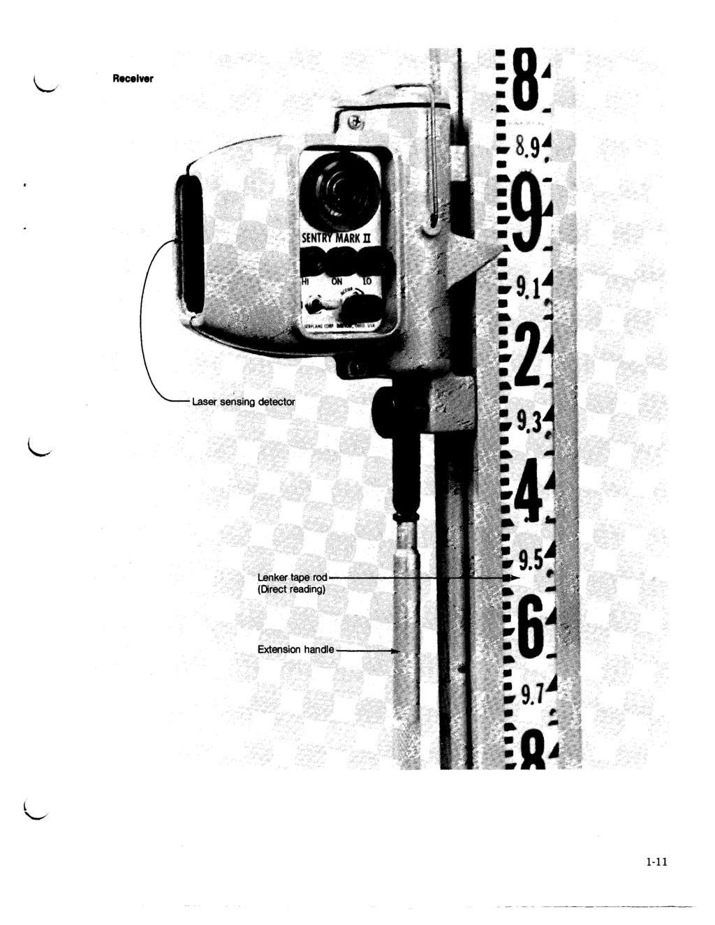
11 Figure 1-5.-Clinometer. (Courtesy of Forestry Suppliers, Inc.) For measuring field elevations a small laser receiver is mounted on a direct-reading survey rod (fig. 1-8). The user moves the receiver up or down the rod until a light or audible tone indicates the receiver is centered in the plane of laser light. The rod reading is then taken directly from the rod, eliminating the need foi. someone to read the instrument. ' Other uses for laser levels and receivers include mounting a receiver on a vehicle, tractor, or earthmoving equipment that has a photoelectric device and telescoping mast that automatically adjusts to the laser plane of light. The receiver also has a mounted control box that senses the distance from the ground to the light beam overhead and reflects this information on a dial as a rod reading. This control system may also be mounted on earthmoving equipment so that the receiver can automatically activate a solenoid-operated hydraulic valve to raise and lower a blade or other earthmoving device. Similar types of receivers and equipment are being used on land drainage equipment. Figure 1-6.-Engineer's dumpy level. (Courtesy of K & E Co.)
 Engineer's Transit This instrument is used primarily for measuring horizontal and vertical angles, for prolonging or setting points in line, for measuring approximate distances by the stadia")
12 Figure 1-7.-Self-leveling level. (Courtesy of K & E Co.) Engineer's Transit This instrument is used primarily for measuring horizontal and vertical angles, for prolonging or setting points in line, for measuring approximate distances by the stadia principle, and for leveling (fig. 1-9). It can also be used as a compass when equipped with a compass needle. Horizontal and vertical plates graduated in degrees and fractions measure the angles. They are mounted at right angles to the axes. Spirit levels are provided for leveling the horizontal plates. A telescope, equipped with a spirit level, is mounted at right angles to a horizontal axis supported by two uprights (standards) attached to the upper horizontal plate. In use, the instrument is mounted on a tripod and is equipped with a small chain and hook to which a plumb bob can be attached. The plumb bob provides a way to center the instrument over a point. The theodolite serves the same purpose as the transit but is generally more accurate. Some models have such features as internal reading, selfleveling, and an optical plummet. Electronic Surveying Systems Some electronic surveying systems can measure and digitally display the slope distance, calculate and display the horizontal distance, electronically sense and display both horizontal and vertical angles, and automatically record these data on a tape or electronic data collector. The data can then be fed into a computer via the tape or electronic data collector, the program can be run, and a printout of coordinates and elevation of each point can be made in a short time. The electronic theodolite (fig. 1-10) is used in
 makes use of laser and infrared beams.")
13 the same way as an engineer's transit, but angles are displayed on a screen in a direct digital readout, allowing fewer errors in reading and interpretation. 'b Electronic Distance-Measuring Equipment Electronic distance-measuring equipment (fig. 1-11) makes use of laser and infrared beams. The design of most units enables most members of a surveying team to use the equipment after a short period of training. Planetable and Alidade The planetable consists of a drawing board attached to a tripod so that it can be leveled, rotated, and locked into the position selected. Drawing paper attached to the board allows survey data to be plotted in the field. The table size most commonly used is 60 by 78 cm (24 by 31 in). Screws are provided for attaching drawing paper to the board. The alidade is an instrument containing a line of sight and a straightedge parallel to it. The line of sight may be a peepsight provided by standards at either end of the straightedge, or it may be a telescope mounted on a standard and fixed with its line of sight parallel to the straightedge. The telescope is provided with a spirit level (ordinarily a detachable striding level), so the line of sight may be horizontal. The telescopic alidade is the more useful of the two instruments. Mapping with it on a planetable is one of the fastest ways to obtain topographic information. The telescopic alidade (fig. 1-12) consists of a telescope mounted on a horizontal axis and supported by standards attached to a straightedge either directly or by means of a post. The telescope is equipped with a vertical arc and a striding or attached level bubble. Many instruments are also equipped with a Beaman stadia arc and a vernier control bubble. The self-indexing alidade (fig. 1-13) is a telescopic alidade in which a pendulum automatically brings the index of the vertical arc to the correct scale reading even if the planetable board is not quite level. All scales are read directly through a microscope. The planetable and alidade are used most effectively for obtaining detail and topography. Because the operator can map the form of the ground while still seeing it, mapping can be done rapidly and an accurate representation of the terrain can be obtained. Level Rods and Accessories The kinds of level rods and accessories generally used by soil conservation technicians are shown in figure All the rods but the range pole are graduated in meters, decimeters, and centimeters or in feet and tenths and hundredths of a foot. 1. The Philadelphia level rod is a two-section rod equipped with clamp screws. Its length is approximately 2.0 m (7 ft), extending to 3.7 m (13 ft). It may be equipped with a round, oval, plain, or vernier scale target. 2. The Frisco or California level rod is a threesection rod equipped with clamp screws. It is about 1.38 m (4 ft 6% in) long, extending to 3.65 m (12 ft). This rod is not equipped for use with a target. 3. The Chicago or Detroit level rod is a threeor four-section rod with metal friction joints. Each section is about 1.3 m (4% ft) long, extending from 3.82 to 5.02 m (12% to 16% ft). It is generally equipped for use with a target. 4. Fiberglass telescoping level rods, usually round or oval, weigh about 1.8 kg (4 lb). The 7.5-m (25-ft) length will telescope into a 1.5-m (5-ft) barrel for transporting. It is not equipped for use with a target. 5. The stadia rod is a two-, three-, or four-piece rod, 4.0 to 5.0 m (12 to 16 ft) long, joined together with hinges and with a suitable locking device to ensure stability. It has metal shoes on both ends. The face is about 8.75 cm (3% in) wide. Designed primarily for use in making topographic surveys, it is not equipped for use with a target. 6. The range pole is a one-, two-, or three-piece pole generally used to establish a "line of sight." A standard metric range pole is 2.5 m long and graduated in 0.5-m segments painted red and white. The English range pole is from 6 to 10 ft long and is graduated in 1-ft segments. Field Books and Special Forms Both looseleaf and bound field notebooks are satisfactory for most Soil Conservation Service (SCS) engineering surveys. However, the looseleaf

14 Figure l-8.-laser level transmitter and receiver. (Courtesy of Laserplane Corp.) 1-10
15 EFM Circular No. Chapter 1 1-9a I Basic and Laser Surveying 1989 Overholt Drainage School March 6-10 Larry C. Brown LENKEB RODS Lenker rods are not a new item and have been use& for many years with levels and transits. The main feature of the Lenker rod is that it allovs the operator to read elevations or portions of elevations directly. Another feature is that there are no subtractions and this may help reduce error possibilities. The Lenker rod differs from a conventional rod in the following ways: 1) The tape is numbered from the top down. 2) The tape is a continuous loop that can be moved so that any number can be placed at the line of sight. 3) The tape can be connected (locked) to the bottom section of the rod. Some Lenker rods have 10 ft. loops and some have 15 ft. loops. The 10 ft loops can only read 10 ft difference in elevation while the 15 ft loops can read 15 it difference in elevation. The 15 it loops have to be adjusted by 5 it to read elevarions correctly when going past the 0-15 ft mark. The field book does not need columns for "back sight", "front sightn, or "height of instrument." The reference of some point on the tape should be recorded to determine if the tape lock has loosened and the tape reset. At turning points (TP), the procedure would be to determine the elevation. Then after the instrument is moved, loosen the tape and set the same reading at the line of sight. The constant vill be unchanged.
16 EFM Circular No. 1 Basic and Laser Surveying 1989 Overholt Drainage School March 6-10 Brom/Galehouse The Laser system with Lenker rod may be used to read elevations directly and avoid some of the note reduction (subtraction and calculations). Record the date, location, weather, kind of survey, people and their job, Lenker rod, laser grade, height, and direction. The column headings would be. STA CONST ELEV GRADE CUT REF ELEV BH# set tin^ Up and record in^ Elevations Select the transmitter location so the height when set up is no more than the maximum rod length (15') above the lowest point to be surveyed. Set up the transmitter following the procedure for the system. Use a firm base and set the tripod solidly. Set the transmitter grade level (0.00%). Take the Lenker rod to the bench mark and find the plane of light with the rod receiver. Lock the sections. Move the Lenker tape until the units digit, tenths, and hundreds of feet of the bench mark elevation are opposite the rod receiver pointer and lock the tape. Unlock the sections. Note: With a bench mark elevation of '. set 6.27 at the rod receiver pointer and use 1050 as a constant (CONST) to be added to the rod readings at each location. Check the reading a second time. Be sure the tape is locked. An error in setting the tape will mean an error in all of the readings from then on. It is good practice to record the rod reference reading in the REF column or as a note, this will allow you to check if the tape has slipped or moved while taking rod readings. Move Lenker rod to next location or station and find the plane of light. Read the tape at the rod receiver pointer.
17 EFM Circular No. 1 Basic and Laser Surveying 1989 Overholt Drainage School March 6-10 Brown/Galehouse 1-9c 9. Record the rod receiver pointer reading plus the elevation constant in the elevation column. Note: The rod sections may be moved or the rod receiver moved as long as the tape remains lbcked as in Item 5. Adjustments of five feet to the readings will have to be made if the reading exceeds the 15' point on a 15' tape. Note: The circuit should be closed by checking back on the bench mark. Ex~~D 1 e : SAMPLE FIELD BOOK PAGE AND CUT SHEET (Bench mark elevation is feet) John Smith Faxm SW 1/4, SE 1/2, Sec 10, T84N, R24W June 4, 1988 J. Jones Warm, Cloudy, Still R. Smith STA CONST ELEV GRADE E W ';Ct 0 CUT 2.81 REF 5.36 This example shows a field book page for direct elevation surveying. The features that are different are the absence of the BS, HI, and FS columns, the addition of the constant column which is optional, and the addition of a reference column to record a reading to determine any unplanned movement of the tape. I have underlined the rod reading in the elevation column.
18

19 Figure 1-9.-Engineer's transit. (Courtesy of K & E Co.) 1-12

20 Figure Electronic theodolite. (Courtesy of K & E Co.) mobs

21 Figure Electronic distance-measureing instrument 1-14


22 Planetable tripod Figure Telescopic alidade and plaetable tripod. Figure Self-indexing alidade. (Courtesy of K & E Co.)
23 I i I RANGE POLE I I1IYI..lllO*I COURIIS' IYCC*C DlEllCt* PHILADELPHIA LEVEL ROD FRISCO or CALIFORNIA LEVEL ROD CO b CHICAGO or DETROIT LEVEL ROD Figure Range pole and surveying rods. notebooks should not be used for project or contract work, or for more complex structures, where the notes might be used as evidence or supporting data in court actions because looseleaf notes are not generally acceptable to the courts. The use of special forms is recommended for recording engineering notes and design data for such practices as terraces, diversions, waterways, small pond dams, and similar work. It is extremely important, however, that the method be uniform and that the forms provide at least the minimum construction-check information. (Refer to TR-62, Engineering Layout, Notes, Staking, and Calculations, USDA, SCS, January 1979.) Field books and special forms should be numbered, identified, indexed, and filed in accordance with SCS standard note-keeping procedures. (Refer to TR-62.) Programmable Calculators Programmable calculators can help in surveying computations by reducing the time in note reduction and computations. Programs are available within SCS that can be used on various types, makes, and models of programmable calculators. Some examples of programs available are stadia note reduction; latitude, departures, and bearing angles; layout of circular curves; intersection of slopes; and survey note reduction. Care and Handling of Surveying Instruments Proper care and protection is necessary to keep the instruments adjusted and operating accurately. Certain procedures and precautions must be observed in using surveying instruments to prevent needless damage and unnecessary wear. Maintaining Tapes and Chains Steel tapes are broken easily if not handled properly. They should not be jerked needlessly, stepped on, bent around sharp corners, or run over by vehicles. The most common cause of a broken tape is pulling on it when there is a loop or kink in it. Slight deformations caused by kinking should be straightened carefully. Insofar as practicable, avoid dragging the tape with markings face down, because abrasive action will remove markings. In spite of reasonable care, tapes will be broken occasionally, so a tape repair kit is necessary if you use steel tapes and chains. After each day's use, wipe the tapes dry and clean them with a clean cloth. After being cleaned, steel tapes should be given a light covering of oil by wiping with an oily cloth. Steel tapes and chains are often wound on a reel for storage and ease of handling. Transporting Surveying Instruments and Accessories Surveying instruments should be carried in the instrument case in the cab of the vehicle, preferably on the floor or in a well-padded equipment box. Rods should be in cases and carried where they will be protected from weather and from materials being piled on top of or against them. Tripods and other surveying equipment should be similarly protected from damage and the weather. Mounting Instruments on Tripod To set up a basic tripod with wooden legs and a screw-top head, remove the tripod cap and place it in the instrument box for safekeeping. Blow dust and sand particles from the tripod head before screwing it on. Tighten the wing nuts on the tripod just enough so that when a tripod leg is elevated, it J J J

24 will drop gradually from its own weight. Carefully remove the instrument from the case. It is best to place your fingers beneath the horizontal bar of a level or the plate of a transit when removing it from the case. See that the instrument is attached L securely to the tripod. When screwing the instrument base on the tripod, turn it first in the reverse direction until you feel a slight jar, indicating that the threads are engaged properly. Then screw it on slowly until you cannot turn it further, but not so tightly that it will be difficult to unscrew when the instrument is dismounted. For most theodolites and self-leveling levels, the tripod head is triangular, with a 1.58-cm (%-in) shifting clamp screw that has a centering range of about 5.08 cm (2 in). To mount these levels, remove from the case and place on the tripod. Then, thread the hold-down screw attached to the tripod into the hole at the base of the instrument. Tighten the screw firmly. Remove the objective lens cap and place it in the instrument case for safekeeping. Attach the sunshade to the telescope with a slight clockwise twisting movement. The sunshade should be used regardless of the weather. When the compass is not in use, be sure the compass needle lifter on the transit or alidade is tightened. Usually the instrument is carried to the field on the shoulder. But in passing through doors, woods, L or brush, hold the instrument head close to the front of your body, so it will be protected. Before crossing a fence, set the instrument firmly in a location where it will be safe and may be reached easily from the other side. Do not allow the instrument to fall. Cleaning and Storing Equipment Always return the instrument to the case before returning from the field. When placing the instrument in the case, loosen the lower clamp screw (transit) and replace the objective lens cap on the telescope. Return the sunshade to the case. After placing the instrument into the case, tighten the transit telescope clamp screw. The lid should close freely and easily. If it does not, the instrument is not properly placed on the pads. Never force the lid; look for the cause of the obstruction. In setting up the instrument indoors for inspection or cleaning, be careful that the tripod legs do not spread and drop the instrument on the floor. Spreading of the legs can be prevented by tying a cord around and through the openings in the legs. Never leave an instrument standing unguarded. Dust and grime that collect on the outside moving parts must be carefully removed from surveying instruments. Use a light machine oil for softening grime on leveling screws, foot plate threads, clamp screws, and other outside parts that you can clean without dismantling the instrument. Place a drop or oil on the leveling screws, and then screw them back and forth to bring out dirt and grime. They should be wiped off with a clean cloth and the process repeated until the oil comes through clean. Do not leave any oil on the moving parts of the instrument. They do not need lubrication. Oil catches and holds dust, which abrades the soft brass parts. Do not remove or rub the lenses of the telescope. These lenses are made of soft glass that scratches easily. Dust them with a clean, soft, camel's hair brush, or wipe them very carefully with a clean, soft cloth to avoid scratching or marring the polished surfaces. If the instrument gets wet during use, dry it with a soft piece of cloth as much as possible before transporting. Upon arrival where the instrument will be stored, remove it from its case and air dry it overnight. Store equipment in a dry place. Level rods, stadia rods, and tripods must be stored in such a manner that they will not warp or become otherwise damaged. They should be fully protected from the elements when not in use. The tripod screws should be loosened. It is best to store level rods flat on at least three supports. Never leave rods leaning against a wall for long periods; they may warp from their own weight. It is satisfactory to store them in a plumb position. A coat of varnish should be maintained on the wooden parts. Electronic surveying equipment should be cleaned and stored in accordance with manufacturer's recommendations.

25 Checking and Adjusting Instruments Engineering surveys cannot be accurate unless the instruments are kept in adjustment. Untrained personnel should not attempt to adjust instruments. Adjustment of instruments is primarily the responsibility of an engineer or an experienced surveyor. However, all personnel using surveying instruments must be familiar with the procedure for checking and making simple adjustments. Major repairs should be done by the manufacturer or a repair shop. The adjustment of an instrument should be checked frequently. An instrument check and adjustment record should be attached inside the lid of each instrument case. Hand Levels To adjust a hand level, hold it alongside an engineer's level that has been leveled and sighted on some well-defined point. The line of sight of the hand level should strike the same point when the bubble is centered. If it does not, adjust the hand level. A quick way to determine if the hand level is in adjustment is to stand in front of a mirror and look through the hand level at the mirror. If you can see your eye looking back at you through the level it is in adjustment. Adjust the Locke level by means of the screw at one end of the level tube. The screw moves the crosswire, which defines the line of sight. Set the index site of the Abney level at zero on the graduated arc. Then raise or lower one end of the level tube until the bubble is centered. The twopeg method of adjustment, as described for the dumpy level, may also be used. Dumpy Level The dumpy level is in adjustment when: (1) the horizontal crosshair is truly horizontal when the instrument is leveled; (2) the axis of the bubble tube is perpendicular to the vertical axis; and (3) the axis of the bubble tube and the line of sight are parallel. See that the eyepiece and crosshairs are in proper focus. Sight the vertical crosshair on a point. Move your head slightly and slowly sideways and observe if the vertical hair moves off the point. If it does, parallax exists. This indicates imperfect focusing. To focus the eyepiece, point the telescope at the sky or at some white surface. Turn the eyepiece until the crosshairs appear as distinct as possible. Retest d for parallax-after a few trials a position is found where there is no parallax. To make the horizontal crosshairs lie in a plane perpendicular to the vertical axis, set up the level and sight a definite fixed point in the field of view. Next, turn the telescope about the vertical axis. If the point appears to travel along the crosshair, no adjustment is necessary. If a point leaves the crosshair, loosen the capstan screw that holds the crosshair ring in place. Turn ring with pressure from fingers or tapping with a pencil and retest until the point remains on the crosshair as the telescope is rotated. Then retighten the capstan screw. To make the axis of the bubble tube perpendicular to the vertical axis, center the bubble over both pairs of leveling screws and then bring it to center exactly over one pair of screws. If the telescope is rotated end for end over the same pair of screws, the bubble will remain centered if in ad justment. If not, the amount of movement away from center is double the error adjustment. Bring the bubble back halfway with the adjusting screw at one end of the bubble tube. Then bring the bubble back to center with the leveling screws. It should remain centered when the telescope is 3 rotated to face the opposite direction. To make the line of sight parallel to the axis of the bubble, perform the two-peg test. First, set two pegs or stakes 60 to 90 m (200 to 300 ft) apart. Then set the instrument midway between them and take a rod reading on each peg with the telescope bubble centered at each reading (fig. 1-15). The difference in the two rod readings, 1.28 m (4.2 ft), gives the true difference in elevation between the pegs. Next, set the instrument at A, preferably the high peg, and read the rod while it is held against or within 1.3 cm (M in) of the eyepiece. Note where the center of the eyepiece touches the rod. You may prefer to take this reading backwards through the telescope. This reading, plus or minus the above dif ference, gives the true reading at B, 2.83 m (9.29 ft), which makes the line of sight horizontal. With the horizontal crosshair on this reading on the rod at B, the line of sight is parallel to the axis of the bubble if the bubble is in the center of the tube. If it is out of adjustment, keep the bubble tube centered and move the horizontal crosshair unlil the line of sight intercepts the true reading on the rod at B. Then repeat the process to check the ad justments made. d

26 , If the bubble fails to center on the self-leveling level, bring it halfway toward the center with the leveling screws and the rest of the way by tightening the most logical adjusting screws until the bubble is precisely centered. Do not loosen any of them. Turn the telescope 180" in azimuth until it is parallel to the same pair of leveling strews. If the bubble does not center, repeat the adjustment. Transit or Theodolite A transit or theodolite is in adjustment when: (1) the axes of the plate bubbles are perpendicular to the vertical axis; (2) the vertical hair is perpendicular to the horizontal axis; (3) the line of sight is perpendicular to the horizontal axis; (4) the standards are at the same height; (5) the line of sight and the axis of the telescope level are parallel; and (6) the telescope is level, with zeros of the vertical arc and vernier coinciding. Before adjusting the instrument, see that no parts, including the objective lens, are loose. To adjust the plate levels so that each lies in a plane perpendicular to the vertical axis of the instrument, set up the transit and bring the bubbles to the center of their tubes by means of the leveling screws. Loosen the lower clamp and turn the plate 180" about its vertical axis. If the bubbles move from their center, half the distance of movement is I the error. Make the adjustment by turning the \L/ capstan screws on the bubble tube until the bubble moves halfway back to center. Each bubble must be adjusted independently. Test again by releveling and reversing as before, and continue the process until the bubbles remain in the center when reversed. When both levels are adjusted, the bubbles should remain in the center during an entire revolution of the plate about the vertical axis. To put the vertical crosshair in a plane perpendicular to the horizontal axis, sight the vertical hair on some well-defined point. Then, leaving both plates clamped, elevate or depress the telescope. The point should appear to travel on the vertical crosshair throughout its length. If it does not, loosen the screws holding the crosshair ring. Tap lightly on one of the screws and rotate the ring until the above condition is satisfied. Tighten the screws and proceed with the next adjustment. To make the line of sight perpendicular to the horizontal axis, set the transit at some point A. Level up, clamp both plates, and sight accurately on some point at B which is approximately at the same level as A. Invert the telescope and set C in line with the vertical crosshair. B, A, and C should be in a straight line. To see if they are, turn the instrument about the vertical axis until B is again sighted. Clamp the plate, invert the telescope, and observe if point C is ih line. If not, set point D in line just to side of point C. Then move the crosshair ring until the vertical hair appears to have moved to point E, which is set at one-fourth the distance from D toward C, since in this case a double reversal has been made. Move crosshair ring by loosening the screw on one side of the telescope tube and tightening the opposite screw. If D falls to the left of C, then move the crosshair ring to the left; but if the transit has an erecting eyepiece, the crosshair will appear to move to the right when viewed through the telescope. If the transit has an inverting eyepiece, the crosshair appears to move in the same direction in which the crosshair is actually moved. The process of reversal should be repeated until no further adjustment is required. When finally adjusted, the screws should hold the ring firmly but without straining it. To make the line of sight parallel to the axis of the bubble, make the two-peg test as described for the dumpy level (fig. 1-15). If the telescope bubble is out of adjustment, raise or lower one end of the telescope bubble tube by turning the capstan nut until the telescope bubble is centered. Note the true reading at B. After this adjustment has been made, examine the vertical arc and the vernier zero-line to see whether they coincide when the telescope bubble is in the center of the tube. If not, move the vernier by loosening the capstan-headed screws that hold the vernier to the standard. Bring the zero lines together, and tighten the screws. All other adjustments may vary depending upon the manufacturer. Field adjustments should be in accordance with manufacturer's recommendations. Planetable and Telescopic Alidade Adjustments of the telescopic alidade require no principles of adjustment other than those for the transit or level. Survey work done with the planetable and the telescopic alidade need not be as precise as that done with the transit, so the adjustments are not as refined. Because the telescope is not reversed in a vertical
27 Line of sight ~ine of sight True horizontal line True horizontal line True difference in elevation 2.93 m-1.65 m = 1.28 m (Instrument midway between pegs) Line of sight - I \ rue horizontal line Figure Adjustment of level (two-peg method).
28 True difterence in elevation 9.61 ft ft = 4.19 ft (Instrument midway between pegs) - A-.- / T C F;-..-- ~- I True horizontal line -- Line of sight
29 arc, no appreciable error is causcd bt~cnuse the line of sight is not perpendicular to lht? ho* izontal axis, or the line of sight is not parallel to the edge of the ruler. It can also be assumed without ;~pp.eciable erfor that the edges of the ruler are straight and parallel a~ld that the horizontal axis is pxallcl tn the surface of' the ruler. Adjust the control level so that its axis is parallel to the ruler. The test and correction are tht~ same as described for adjustment of the plate levels of the triinsit except that the plak or ruler is reversed by carefully marking a guideline on a planetable sheet. The board is not reversed. Adjust the vertical crosshair so that it lies in a plane perpendicular to the horizontal axis. The test and adjustment are the sanie as for the transit. Adjust the telescope level so that its axis is parallel to the line of sight. The test and correction are the same as described fir adjustment uf' the irlescope level on the transit. If the alidade is one in which the telescope can be rotated about its axis in a sleeve. the two following adjustments should be used. I<'it.st, make the line of' sigl~t coit~cide mith the axis of the telescope sleeve. In making the test, sight the intersection of the crosuliairs on some well-defined point and rotate the telescope carefully through 180". Generally, the rotation rs l i i ~lkitd 1)y a shoulder and lug. If the intersection of the crosshairs stays on the point, the line of sight coincides with the axis of the telescope sleeve. Second, make the axis of the striding level parallel to the telescope sleeve and therefore parallel to the line of sight. In making the test, place the striding level on the telescope and bring the bubble to the center of the level tube. Then carefully remove the striding level, turn it end for end, and replace it on the telescope barrel. If the bubble returns to the center of the tube, the level is in adjustment. If the bubble is not centered, it should be brought back one-half of the displacement by means of the adjusting screw on one end of the bubble tube. Then bring the bubble to the center by means of the tangent screw and repeat the test. Adjust the vernier to read zero when the line of sight is horizontal. This adjustment is the same as described for the transit under "Adjustment of 'I'elescope Bubble." Electronic and Self-Leveling Surveying Equipment The adjustments to this equipment will vary depending upon the manufacturer. Field adjustments should not be attempted unless recommended by the manufacturer. J
30 Hand Signals Survey Notes and Symbols A good system of hand signals between members of a surveying party is a more efficient means of communication than is possible by word of mouth. Any code of signals mutually understood by the persons handling the instrument and the rod is good if it works. When the "shot" is finished, prompt signalling by the instrument handler allows the rod holder to move promptly to the next point. It is also desirable to have a system of signaling so that numbers can be transmitted from rod holder to instrument handler or vice versa. The code of signals illustrated in figures 1-16 and 1-17 is suggested. This code may be enlarged upon or altered to suit the needs of the job. A definite code, however, should be determined and mutually understood in order to speed up the job. Two-way radios are now being used extensively. l'hpy are relatively inexpensive and an efficient llltbi~ns of communication within a survey party. Field notes are the record of a survey, with data recorded so that they can be interpreted readily by anyone having knowledge of surveying. Notes should identify the survey by title and should include location and purpose, identification of survey party members and duties, date, and weather conditions. Notes should be recorded in the field notebook at the time wdrk is done and not left to memory or later recopied from temporary notes. All data pertaining to one survey or project should be entered in the same field book or series of field books. Books should be identified and indexed according to SCS standard notekeeping procedures before notes are recorded. (Refer to TR-62.) Notes consist of numerical data, explanatory statements, and sketches. The form in which notes are recorded varies with the kind of survey, such as bench level circuits, profiles and cross sections, transit-traverses, etc. However, a uniform system for each kind should be followed insofar as possible. Sample forms of field notes are illustrated throughout this chapter and in TR-62. Sketches in field notes are important in conveying information and correct impressions to others plotting data or using the information in engineering design. Sketches should be drawn approximately to scale, using standard SCS mapping symbols. Some of the more commonly used symbols are shown in figures 1-18 and 1-19.
31 Move in this direction Move in this direction Plumb rod Plumb rod Turning point Step away from inst. circle Use long rod Observation completed or Move on or Understood Wong face or Check clamp or Rod upside down Move down Move up Turnmg point (by rod man) Wave rod slowly from side to side Come in Figure Code of hand signals (instructions).
32 'ONE" 'TWO" 'THREE" 'FOUR" 'FIVE" 'SIX" 'SEVEN" 'EIGHT" 'NINE" 'ZERO" 'PLUS" Figure Code of hand signals (numbers).
33 - hod motor road {- E Farm or ranch operations, Perennial streams Poor motor or boundary e private rood {Z -; Z Ownership boundary Natural barrier or escarpment- TRAIL Trail Field or land use boundary Vegetative waterwav ---..= ---d Inclusion tie Railroad ttt-+ Pond or lake Power-transmission line Gully 0 (Label Burled if under- ~ ock outcrop 44 4 J Wet spot '4' ground) * Spring Building Intermittent Streams,.-. Manh Formsteo d H -... Fence... -x-x- Electric fence... EXISTING 4+w& Shelterbelt... * * Stream bank protection PLANNED Dike or levee H+++ MwHw Pipeline... H HW Permanent sprinkler laterol HoHeH F**i - Portable sprinkler lateral Flume or syphon... 7'>>* CANAL CANAL - CANAL -- CANAL- Irrigation ditch... C---C Canal (label)... Pickup ditch... -P-P- Diversion D-CD- Drainage or open drain Closed or tile drain /-I- -/ +'- /- +++-t nnn!--lc-lc-l 09.0 =-- -*-4-r- ---&*- C -..*- *-be L-. Division box or turnout Pipe riser Diversion or spreader dam... Check dam or gully plug.....-b ~rop structure...& Dam and reservoir... Stock pond, tank or cham... a Spring development... b Spring and trough....e Trough.... w LICU Well (label)... wnm TANK Water tank (label)... pump... m Wt ground... I'ide or flood gate... -* -T-*l -E- Small reservoir... Figure Symbols for soil and water conservation engineering maps and drawings.
34 UNIFIED SOIL CLASSIFICATION SYSTEM SYMBOLS Well graded gravels; gravel-sand mixtures Poorly graded gravels Silty gravels; gravel-sand-silt mixtures Clayey gravels; gravel-sand-clay mixtures Well graded sands; sand-gravel mixtures Poorly graded sands Silty sand Clayey sands; bnd-clay mixtures Silts; silty, v. fine sands; sandy or clayey silts Clays of low to medium plasticity; silty, sandy or gravelly clays Inorganic clays of high plasticity; fat clays Elastic silts; micaceous or diatomaceous silts Organic silts and organic silty clays of low plasticity Organic clays of medium to high plasticity UNCONSOLIDATED MATERIALS Flgravel mlsi1t PTbble sand m c l a y 0 o.... D&? oulders sand, silt, clay, Elpea F] plgravel,..o.: 6 sandy P... gravelly CJ q gravelly O gravelly vl silty sandy gravel, sand. M s i l t. a c l a y. F l c a r - o clayey '..-7 clayey clayey silty + eous * r] HT~W;~, M;$.dt m l m m i c ~10rganic I silt I clay,% clay * to be added to Standard Symbol when significant amounts of dispersed gypsum or calcified zones are present in the section. Figure Soil symbols for soil and water conservation engineering maps and drawings.

35 Measurement of Horizontal Distancen Pacing, taping, stadia, and electronic devices are used for measuring horizontal distances. Pacing Pacing may be used for approximate measurement when an error as large as 2 percent is permissible. Measurements by pacing generally are permissible for terrace and diversion layouts, preliminary profile work, and gridding for surface drainage surveys. Measurement by pacing consists of counting the number of steps between two points and multiplying the number by a predetermined "pace factor," which is the average distance in meters or feet per step for each individual. It can be determined best if one walks, in a natural stride, a measured distance, usually 150 m (500 ft), several times. It should be paced enough times to make certain the number of paces for the distance does not vary more than two or three. The "pace factor" then would be the distance in meters or feet divided by the number of paces. The "pace factor" may vary with the roughness and slope of the ground. Adjustments should be made to take care of these variations. Some people prefer to use a stride instead of a pace. It consists of two paces, so the "stride factor" would be two times the "pace factor." Taping Taping is the method of measuring horizontal distances with a tape. Survey distances are recorded by stations, which are usually 30 m (100 ft) apart. The fractional part of a distance between full stations is called a plus station. Fractions of a meter (foot) are indicated by decimals, to the nearest 0.01 m (0.1 ft), depending upon the accuracy of the measurement required. For example, a point on a line m (309.2 ft) beyond station 3+05 m (10+00 ft) is indicated as station ( ). Stakes set along the line are marked with a waterproof lumber crayon, known as a "keel," or with an ink marker. Markings are placed on the face of stakes so that as a person walks along the line in the direction of progressive stationing, the station markings can be seen as each stake is approached. Accurate taping with a steel tape or chain re- quires skill on the part of the surveyor in the use of plumb bobs, steel taping pins, range poles, hand levels, and tension indicator apparatus. This manual is written for execution of the less difficult conservation work. The following procedure should be observed: 1. Keep tape on line being measured. 2. Keep uniform tension on tape for each measurement. 3. "Break" chain on slopes as necessary to keep chain level (fig. 1-20). 4. Accurately mark each station. 5. Keep accurate count of the stations. The following procedure is generally used for chaining a line: 1. If the line to be measured is a meandering line along a drainage ditch or gully channel, the measurements are taken parallel, or nearly so, to the meandering line. If the line is straight, a range pole is set ahead on the line as far as can be seen, or the direction is marked by a tree, fence post, or other convenient point. This mark is used in sighting in a straight line from the point of beginning. 2. For purposes of this explanation, it will be assumed a straight line is to be measured, and a stake has been set at the point of beginning marked (See section on "Prof~les and Cross Sections" for other methods of stationing the beginning station.) 3. The lead surveyor takes the zero end of the tape and advances in the general direction of the line to be measured. When the end of the tape is near, the rear surveyor calls out "chain." This signals the lead surveyor to stop. 4. The rear surveyor then sights-in the lead surveyor on the line to be measured and holds the required distance mark of the tape exactly on the beginning stake. The lead surveyor pulls the tape straight and reasonably tight and sets a stake or pin on line exactly at the "zero" end of the tape. 5. Each time the rear surveyor calls out the station number, the lead surveyor should answer with the number at that stake, indicating the front station. In so doing, the rear surveyor can mentally check and verify the addition to the forward station. On slopes, the uphill end of the tape should be held on the ground and the surveyor at the other end should hold the tape so that it is level or at least as high as the surveyor can reach and "plumb" down by means of a plumb bob. On grades too steep for level taping, the tape should be "broken" in such convenient lengths that it can i LJ d
36 Sta m-distance measured by "breaking" chain and plumbing * p m-distance if measured along the ground -r( Sta ft-distance measured by "breaking" chain and plumbing ft-distance if measured along the ground L Figure Breaking chain.

37 be held approximately level, plumbing down to the ground. Figure 1-20 illustrates the process of breaking chain and indicates the errors that can occur if this is not done on steep slopes. Stadia The stadia method is a much faster way to measure distances than chaining, and is sufficiently accurate under some conditions. The equipment required for stadia measurements consists of a telescope with two extra hozizontal hairs, called stadia hairs, and a graduated rod. Most transits and telescopic alidades, and some engineering levels, have stadia hairs. One of the stadia hairs is above the center horizontal crosshair and the other is an equal distance below it. To take a stadia measurement, observe through the telescope the interval in meters or feet on the rod between the two stadia hairs when the rod is held vertically on some point. The stadia rod must be help plumb because considerable error in distance can result if it is not. this interval, called the stadia interval, is a direct function of the distance from the instrument to the rod. On most instruments the ratio of this distance to the stadia interval may be taken as 100 to 1 with no a p preciable error. The exact ratio for instruments with stadia hairs is usually indicated on the card placed in the instrument box. To determine the distance from the instrument to any given point, observe the stadia interval on the rod help on the point and multiply this interval by 100. In reading stadia intervals, it is usually convenient to set the lower stadia hair on some even meter or foot mark and read the interval to the upper stadia hair. When the distance is such that one of the stadia hairs falls off the rod, one-half the interval may be read between one stadia hair and the horizontal crosshair. When this is done, the distance will be twice the interval that is read on the rod times 100. The distances obtained by the stadia are as measured along the line of sight from the instru- ment to the rod. If the line of sight is on an appreciable grade, you will need to make a correction to obtain the true horizontal distance. The correction can be made by the use of tables or a stadia slide rule, either of which give both horizontal and vertical distances from stadia readings on various grades. For slopes less than 5 percent, the horizontal distance will be within 0.3 percent of the measured distance and may be used without need of correction. Aerial Photographs Horizontal distances may be obtained between points on an aerial photograph by direct scaling if the scale of the photograph is known. If the scale is not known or if you want to check it, the scale may be determined as follows: 1. Select two welldefined points on the photograph located so that measurement with the chain can be made conveniently between them on the ground and, also, so that the measurement between them on the photograph will cross a good portion of the center section of the photograph. 2. Measure, in centimeters (inches), the distance (A) between the points on the photograph. 3. Use a chain to measure, in meters (feet), the distance (B) between the points on the ground. 4. Scale of the photograph = centimeters per meter (feet per inch). The scale % t us determined may be applied to other measurements of the same photograph, although the measurements near the edge may be affected some by the distortion of the photograph. Electronic Equipment To take a measurement with electronic measuring equipment, simply sight the unit onto a reflector target. Then, press the range button and numerals will appear on the display screen showing the distance in meters (feet). This procedure may vary slightly depending upon the type of equipment used. a d
 leveling.")
38 Differential Leveling LA, Planning and establishment of all permanent practices used in soil and water conservation work require information regarding the relative elevation of points on the earth s surface. Three principal methods are used to determine differences in elevation: barometric, trigonometric, and differential (or spirit) leveling. Differential leveling, the method most commonly used, is the only one explained here. It utilizes the phenomenon that a spirit level can be used to fix a line of sight perpendicular to the action of gravity. This line of sight can then be used to determine differences in elevation between nearby points on the earth s surface. Common Terms Used in Leveling Common terms used in leveling (see fig. 1-21) are bench mark, turning point, backsight, foresight, and height of instrument. A bench mark is a point of known or assumed permanent elevation. Such points may be marked with a brass pin or a cap set in concrete, a cross or square mark cut on concrete, a lone metal stake driven into the ground, a specifically located point on a concrete bridge, culvert, or foundation, or similar objects that are not likely to be disturbed. Temporary bench marks (TBM) are points of known or established elevation usually provided for convenient reference in the course of surveys and construction when permanent bench marks are too far away or are inconveniently located. Such bench marks may be established on wooden stakes set near a construction project or on nails driven into trees. Bench marks on trees will have more permanence if set near the ground line where they will remain on the stump if the tree is cut and removed. Federal, state, and municipal agencies and private and public utility companies have established bench marks. These bench marks are located in nearly all major cities in the United States and at scattered points in less populated areas. They are generally bronze caps securely set in stone or concrete with elevations referenced to mean sea level. Their primary purpose is to provide control points for topographic mapping. They are also useful as points from which other bench marks may be established for public or private projects. Such bench marks should be used, when convenient, for the more important surveys. Caution should be exercised in using existing bench marks in areas of subsidence due to mineral or water removal. A turning point is a point on which the elevation is determined in the process of leveling, but which is no longer needed after necessary readings have been taken. A turning point should be located on a firm object, whose elevation will not change while moving the instrument setup. A small stone, fence post, temporary stake, or axe head driven firmly into the ground usually is satisfactory. A backsight is a rod reading taken on a point of known elevation. It is the first reading taken on a bench mark or turning point, and is taken immediately after the initial or new setup. A foresight is a rod reading taken on any point on which an elevation is to be determined. Only one backsight is taken during each setup; all other rod readings are foresights. Height of instrument is the elevation of the line of sight. It is determined by adding the backsight rod reading to the known elevation of the point on which the backsight was taken. Setting Up the Level Before attempting to set up the level, be sure that the tripod wing nuts have been tightened so that when held horizontally each leg will barely fall under its own weight. Next, holding two tripod legs, one in each hand, place the third leg on the ground. Using the third leg as a pivot, move the held legs until the footplate is nearly horizontal. Then, without altering the horizontal position of the footplate, lower the two legs to the ground. Apply pressure to the legs to ensure a stable setup. Be sure that the tripod legs are spread at such an angle that the tripod is stable and that objects may be viewed through the telescope from a convenient posture. For a level with four leveling screws, line up the telescope over one pair of leveling screws and center the bubble approximately. The process should be repeated with the telescope over the other pair. Continue this procedure until the bubble remains centered, or nearly so, for any position of the telescope. Final centering of the bubble is usually easier if only one screw is turned rather than trying to adjust two opposite screws at the same time. The leveling screws should be tightened only enough to secure a firm bearing. For self-leveling levels with three leveling screws, turn the telescope until it is parallel with two of the 1-31
39 BM No. 2 TP No. 3 EL m EL m Figure Method of differential leveling (metric). BM No. 2 EL ft TP No. 3 EL ft Figure 1-2l(a).-Method of differential leveling (English). screws and bring the bubble to the center using both the screws. Then with the third screw, bring the bubble to the center of the circle. When you rotate the telescope, the bubble should remain centered in any position. If it doesn't, the bubble needs adjustment. (Refer to adjustment section.) Before attempting to take sights, focus the crosshairs with the eyepiece. Point the telescope at some light surface such as a white building or the sky and turn the eyepiece slowly in or out until the most distinct appearance of the crosshairs is obtained. Then focus the telescope (by means of the focusing screw) on a level rod, held at some point about 30 m (100 ft) from the instrument. Then move your eye slowly up and down to observe if the crosshair apparently moves over the face of the rod. If the crosshair does not appear to move, it is properly focused. If you detect movement, further adjustment is necessary. Once the eyepiece has been adjusted, no further adjustments are necessary so long as the same individual uses the instrument. After focusing on the rod, center the bubble exactly in the level vial before taking the rod reading. Be sure that the reading is taken with the rod in a vertical position,and that no foreign material prevents clear contact between the rod and d

40 L c/ point to be read. On bench marks and for more precision, some surveyors ask the person holding the rod to move the rod back and forth over the center, using its base as a pivot. A rod level could also be used for this purpose. The minimum reading thus observed is the true vertical reading. Be sure not to lean on the instrument or step close to the tripod legs, because this may throw the instrument off level. Bench Level Circuit The procedure and field notes used in running a bench level circuit may be considered as the basic system for all differential leveling. The beginner should be throughly familiar with this basic system. A bench level circuit is run to determine the relative elevations of two or more bench marks. The circuit may start from a highway or U.S. Geological Survey (USGS) bench mark or from some point of assumed elevation. A bench level circuit is frequently run as a part of a profile, cross-section levels, or topographic survey. The basic procedure and notes are the same in any event. On large projects, the bench level circuit should be run before all the other survey work, or much more work will be required to carry corrections through the survey notes if mistakes occur. Bench levels should always be "closed" on the starting point. That is, after the last bench mark is set, levels should be run back to the starting point, unless the circuit can be closed on another proven point. The procedure for running a bench level circuit is as follows: 1. The level is set up at some convenient point between the starting bench mark and the next bench mark or turning point, but usually not over 120 m (400 ft) from the starting bench mark. It is usually difficult to read the level rod at distances over 150 m (500 ft). A little practice will reveal what should be the limiting distance for the particular level being used. Keeping foresight and backsight distances approximately equal makes it possible to compensate for any adjustment errors in the instrument. 2. The instrument handler begins the field notes by recording the following information (fig. 1-22). (a) Location of survey, including name of farm, farmer, or project. (b) Type of survey such as design survey, construction layout, construction check, or similar description. (c) Column headings on left-hand sheet. (d) Names of surveyors. (e) Date of survey. (0 Description of starting bench mark. Include reference to the field book in which the elevation of the bench mark was originally recorded. If it is a new bench mark with an assumed elevation, it should also be described. However, this assumed elevation should be in even meters or feet, such as 30 m (100 ft). 3. With the rodholders holding the rod on the bench mark, the instrument handler observes the rod reading and records it in the backsight column opposite the station (Sta.) BM 1. Referring to figures 1-21 and 1-22, note that the backsight on BM 1 was 2.08 m (6.82 ft). This reading added to m ( ft), the elevation of BM 1, gives m ( ft). This is the HI, or elevation of the line of sight. 4. The rodholder then moves ahead and picks out a convenient point for a turning point (TP), or drives a small stake into the ground for this purpose. The instrument handler turns the telescope and takes a rod reading on this turning point and records this reading in the foresight (FS) column opposite TP 1. In figures 1-21 and 1-22 the foresight for TP 1 was 1.58 m (5.17 ft). This reading subtracted from the HI, m ( ft), gives m ( ft), the elevation of the turning point. 5. The instrument handler then picks up the level, moves ahead, and goes through a process similar to that described above, taking a backsight on TP 1, and a foresight on a new turning point ahead. 6. After the elevation of the last bench mark has been determined, the survey party runs levels back to the starting bench mark to "close" the circuit. Note in figure 1-22 that the foresight on BM 3, the last BM in the circuit, was 1.11 m (3.64 ft), giving an elevation of m ( ft) for BM 3. In making the return run, the instrument handler resets the instrument and uses BM 3 as the turning point to include it in the closed circuit. In a bench level circuit, BM's should always be used as turning points. 7. After the final foresight on the starting BM is taken, the "error of closure" can be determined.
.")
41 Figure 1-22.Sunrey notes-bench-level circuit. This is the difference between the actual elevation of the BM and the elevation computed from the final foresight. Figure 1-22 shows that the elevation computed from the final foresight was 0.01 m too low or 0.02 ft too high. Length of circuit is about 0.8 km (0.5 mi). To determine permissible error, use the formula given in accuracy standards (table 1-1). Permissible error is 0.02 m= 0.03 m or 0.10 = 0.7 ft. Actual error is 0.01 m (0.02 ft), which is acceptable. Level note computations should be checked by adding the backsight and foresight columns as shown in figure The difference should equal the error of closure and should be in the same direction-that is, plus or minus. This check merely proves the accuracy of the addition and subtraction performed in the notes. If the foresights and backsights do not check, computation of elevations and heights of the instrument will have to be rechecked until the mistake is found. Profiles and Cross Sections The object of profile leveling is to determine the elevation of the ground at measured distances along a selected line. These elevations can then be plotted on profile paper at selected scales so that studies can be made of grades, depths, and high and low spots, and so that estimates can be made of quantities of cuts and fills.
42 x J. Brown %> Wrrh Level Cirsclit I ) U. Smith 7/lb]71, Figure Survey notee-bench-level circuit (metric). Cross sections are simply profiles usually taken at right angles to a base line such as the center of a road, ditch, gully, or other selected base line. Cross sections may be run along with profile levels, or they may be run after the profile line has been staked and profiles have been taken. On many projects it is customary to stake out a ' traverse line with a transit and tape before running the levels for profile and cross sections. The traverse line may be the centerline of a drainage ditch, dam, irrigation ditch, or an offset line. It may be a continuous straight line, a broken line, or a curved line. The procedure for running traverse surveys is as follows: 1. The procedure in running a profile, and recording field notes, is essentially the same as in running bench levels, except that rod readings are taken on the ground at field stations and at major breaks in slope between stations. Distances between readings are measured and recorded by full or plus stations. Normally, a line on which a profile is to be run is located and stationed before or during the time profile levels are taken. 2. Whenever possible, a BM should be set near

43 Check L eve& B.Mf I I I Figure 1-2UaI.-Survey noteebench-level circuit (English). the starting point stake. If this cannot be done, it will be necessary to run levels from the nearest BM to the starting point. Location of the starting point stake is described in the notes so that it can be relocated if it is pulled out or otherwise lost. The start of the profile should be a full station. It may be or any other selected full station. Frequently, it is desirable to use a higher station such as , if in meters, or , if in feet, where it may be necessary to run the profile both ways from the starting point. This avoids having to record minus stationing, which is always confusing. Normally, the starting station for surveys involving streams, waterways, irrigation canals or ditches, and gullies should be located at the upstream end and proceed in the direction of flow. In some cases, however, topography and the system to be surveyed might be such that the survey could be done quicker and easier by locating the starting point at the downstream end and proceeding upstream. This is especially true for drainage surveys. In all surveys that might involve computations for water surface profiles by computers, the stationing numbering should proceed progressively downstream. The sample field survey notes (fig. 1-23) illustrate the use of a station other than for the starting point. 3. After establishing a starting point, the instrument handler sets up the level and reads a backsight on the BM to determine the HI and then observes a rod reading with the rod held on the ground at the starting point. A ground rod reading
44 Figure Survey notes--profile and crass section (metric). is taken at each full station and at such plus stations as are necessary. Ground rod readings are taken to the nearest 0.01 m (0.1 ft), and ground elevations are computed only to the nearest 0.01 m (0.1 ft). 4. When the rodholder has moved to about 90 to 100 m (300 to 325 ft) away from the instrument, a TP is taken on a solid object. The instrument handler then moves ahead, sets up, takes a backsight on the TP, computes a new HI, and continues as before. Rod readings and elevations on TP's and BM's should be read and recorded to m (0.01 ft). 5. If a transit line has not been run previously, the instrument handler should draw a sketch in the field book to indicate changes in direction of the profile and its relationship to nearby landmarks. Stations should always be measured and recorded at all important points along the profile line, such as at branch ditches, subsurface drain laterals, gullies, overfalls, culverts, bridges, roads, fence lines, headgates or takeouts, drops, checks, and similar features. It is useful to have this information in studying the profile for design and later in staking construction work on the ground. 6. Frequently, it will be desirable to set a hub
45 Figure Survey notes--profile and cross section (metricbcontinued. stake driven flush with the ground every 150 m (500 ft) or less in order to "tie in" or relate other survey work to the profile. 7. The sample survey notes (fig. 1-23, 1-23(a)) indicate the method of recording cross-sectional notes when cross sections are run at the same time as the profile. Stations are selected where cross sections are wanted. The stationed line or transit line is used as the base line from which measurements are taken to both sides at right angles to the base line. Sometimes an offset line is used, and cross sections are taken only to one side or both sides as is deemed necessary to obtain the information desired. A rod reading is taken on the stationed line at the station and recorded on the right-hand page opposite the appropriate station. For example, station (fig. 1-23) or (fig. 1-23(a)). Since this reading was taken on the base line, 3.41 m (11.2 ft) is recorded directly on the centerline of the righthand sheet of the field book. The rodholder then moves out at right angles to the base line with the rod and one end of the tape to the first major break in ground slope. The rear chainhandler stands at the base line, reads and calls off the distance from this point to the rodholder. The instrument handler reads the rod and records the distance and rod
46 fs or Grode Rod rh Figure 1-23.Survey notes-profile and cross section (metric)--continued %-or S.E. corner gr nery found~tion reading either to the right or left of the centerline of the right-hand sheet, depending on which side of the line the shot was taken. The rod reading and distance are recorded as T o r v, the top number being the rod reading and the bottom number the distance. The process is continued until the cross section is run out as far as necessary in one direction. The rodholder then returns to the base line, and a similar process is repeated in the opposite direction. Elevations along the cross-section line generally are not computed in the field unless they will be plotted in the field. This work is usually done in the office. It is not essential that the zero of the cross section be the centerline of the gully, ditch, or stream. In some cases, the profile line may be along the bank of a ditch. In any case, the zero of the cross section is on the base line. The instrument handler must indicate in the field notes the direction of the cross section so that it will be clear. It is standard practice to refer to "right" and "left" when one faces the direction of progressive stationing of the profile line. A cross section taken at a proposed structure site should be located so that this line may be reproduced later if necessary. This can be done by setting a hub stake at the zero point of the cross
47 Figure Survey notes-profile and cross section (metricbeontinued. section and one or more additional stakes on the cross-sectional line 10 to 30 m (30 to 100 ft) from the zero point. These stakes should be driven nearly flush with the ground so that they will not be disturbed, and guard stakes should be driven beside them for protection and ease in finding. Use of Grade Rod In surveys for construction layout and construction checking, the use of grade rod readings, determined from the established HI, eliminates the need for converting rod readings to elevations at each layout or checkpoint. Grade rod is the reading that would be obtained from the present instrument position if the rod were placed at the planned grade. (Grade rod = HIplanned grade elevation). When the HI is above grade elevation, the grade rod has a plus value and is so marked in the notes, such as m (+6.3 ft). If the HI is below grade elevation, the grade rod has a minus value and is so marked, such as m (- 8.3 ft). To find the cut or fill in construction layout surveys, the actual ground rod reading is subtracted
 and the planned grade elevation is 74.07 m (243.0 ft), the grade rod would equal 75.99 m (249.3 ft) minus 74.07 m (243.0 ft) or 1.92 m (6.3 ft). If the foresight of the point were 2.")
48 Figure 1-23(a).-Survey notes-profile and cross section (English). from the grade rod. If the result has a minus value, a fill is indicated. If the result has a plus value, a cut is indicated. For example: If the HI is m (249.3 ft) and the planned grade elevation is m (243.0 ft), the grade rod would equal m (249.3 ft) minus m (243.0 ft) or 1.92 m (6.3 ft). If the foresight of the point were 2.99 m (9.8 ft), then 1.92 m (6.3 ft) minus 2.99 m (5.8 ft) would equal m (- 3.5 ft), indicating a fill. If the foresight were 1.55 m (5.1 ft), then = m ( = +1.2 R), indicating a cut (figs and 1-24(a)). Figures 1-25 and 1-25(a) illustrate survey notes for design, construction layout, and construction check of a small field ditch project. A few prior random shots with a level indicated the ditch could be constructed to provide the necessary surface drainage on a m per meter (ft per foot) bottom grade with a 0.30-m (1-ft) drop at its outlet to the bottom of the main ditch. Setting Up Slope Stakes Slope stakes are set as part of a layout procedure widely used to guide and check earthwork construction. The procedure given can be applied to excavation of ditches, diversions, spillways, and other embankment work, such as levees and dikes, that requires construction to specified slopes. Figures 1-26 and 1-26(a) show an example of the use of the grade rod method to set slope stakes for an earth dam. In the example, assume that the earth fill will
; upstream side slope, 3:l; downstream side slope, 2:l; elevation at top of settled fill, 31.08 m (101.9 ft).")
49 Figure 1-23(a).-Survey notes-profile and cross section (Englishb-continued. be staked to the following dimensions: top width, 2.4 m (8 ft); upstream side slope, 3:l; downstream side slope, 2:l; elevation at top of settled fill, m (101.9 ft). Also, assume location and elevation of bench mark and centerline of dam have been previously staked, and proceed as follows: 1. Run levels from BM to point of convenience at damsite and compute HI = m ( ft). (See figures 1-27 and 1-27(a)). 2. Compute difference between HI elevation and top of fill: = 0.16 m ( = 0.5 ft). This is grade rod at station 0+30 m (1+00 ft). 3. With centerline rod reading of 1.28 m (4.2 ft) at station m ( ft), compute elevation of ground surface, then compute fill height, = 1.12 m ( = 3.7 ft). This can be done also by merely subtracting the difference between HI and top of fill from the centerline rod reading, = 1.12 m ( = 3.7 ft). 4. The centerline fill has now been determined. To set the slope stakes at right angles to the centerline you must keep in mind side slope; top width; berm width, if any; and fill (or cut) at the centerline. The distance out from the centerline at which a slope stake is correctly set is given by the relationship: d = + hs (without berm) or d = f + b + hs (with berm) where d = distance in meters or feet, w = top width
 in meters or feet, s = side slope, and b = berm width in meters or feet. 5.")
50 44 +OO 45,OO /2 au* Correct el&-*d.p2 5l3 34 $iff: 00.m I Figure 1-23(a).--Survey notes-profile and crow section (Englishkcontinued. in meters or feet, h = fill (or cut) in meters or feet, s = side slope, and b = berm width in meters or feet. 5. For the first trial at setting a slope stake on the upstream side of the dam at station 0+30 m or 1+00 ft, measure a distance at right angles to the centerline stake of d = + 3( ) = 4.56 m [d = + 3( ) = 15.1 ftl. Take a rod reading at this point. In the example the rod reading was 1.13 m (3.7 ft), which gave a distance of d = + 3U ) = 4.11 m [d = # + 3( ) = 13.6 ftl. When the rod was moved from 4.56 to 4.11 m (15.1 to 13.6 ft) from the centerline, the rod reading again was 1.13 m (3.7 ft), so the stake was put in and marked (figs. 1-27, 1-27(a)). Allowance for settlement should be marked on the slope stake. The distance, rod reading, and elevation are recorded in the field book. 6. Slope staking is a trial and error method. Practice will develop judgment in making distance adjustments so that a minimum of trials will be necessary to find the location for the slope stake. The same procedure is used to find the downstream slope stake at station 0+30 m (1+00 ft) and the stakes at the other stations.
51 ,....,.... I ( , * ,.. -C.. t I,..,. < a,... i Figure 1-23(a).--Survey notee--pde and mom &ion (Engl W-continued.
52 \ Grade rod 1.92 m Sround rod 2.99 m I Figure Determining cut and fill with grade rod (metric). -.I- ' Fill 3.5 ft 1 I A Ground rod Ground rod 5.1 ft I - Cut 1.2 ft - Figure 1-24(a).-Determining cut and fill with grade rod (English).
53 F 5. m G~de lod IIer. ot bnncd tlev. JO* Ctiroge Ditch "I Des~w Sur. / Figure uwey notec-diteh survey wing grade rod (metric).
54 . F.S. or Grad. Rod X T. Edwrds.J; JW~S Ditch *I I. I(.Y +b/7)/77 Pwip + Cons? Luy - 4:lis.s. 1 4 V SM Figure l-25.-survey notes-ditch survey using grade rod (metric)--continued.
55 Figure Survey notes-ditch survey using grade rod (metric)--continued. J. Junes 7 Ur.Ditch#/ ( Consf, check
56 Figure 1-25(a).-Survey notes-ditch survey using grade rod (English).
57 Figure 1-25(a).-Survey notes-ditch survey using grade rod (English)-continued.
58 Figure 1-2Ma).--Survey ndegaitch awey using grsde rod (Engliah)-continued.
59 q of fill Cross wction pwp.ndicular to of fill \ Top of settled fill elev ml A o t l n a ~ groundline \section. Crest elev m Profik along q of fill Sta Q Fill Sta Sta Sta Plan slope stakes "il'way Spillway lj- Sta Figure location of slope atakw (metric).
60 fill Slope stake Cross section perpendicular to of till \ Top of settled fill elev ft, m Stationing stakes Crest elev ft Profile along of fill Sta O+89 'L Fill Sta Sta Sta 0+30 Figure 1-26(a).-Location of elope stakes (English). Plan Spillway Sta O+OO
61 Figure Survey noteeslope stakes for dam (metric).
62 St0 8m 9 wen2 -a & f 3D 0 ++o TP-I Ot.48 a t5z -- FS or Grade Rod- - Elev or 'lonned Clcv 3025R s za s 3 1.0s - 0 ~ O U k9_ IV-%_ Of7Z- ot Oi- 78 >CS-ENG ;LS.'I+l 31.0s If GI Figure Survey notes-slope stakes for dam (metric)-continued.
63 Figure 1-27(a).--Survey notes-slope stakes for dam (English).
64 Figure 1-27(a).-Survey notas--slope stakes for dam (Englishkontinued.

65 Topographic and Control Surveys Topographic surveys, to obtain ground relief data and locations of natural and constructed features, are the basis for many soil and water conservation projects. Such surveys involve both control surveys and surveys for topographic features. A relatively few points or stations are established by the control survey. They are so arranged that they can be easily observed and measured by triangulation, traverse, or grid. Elevations of such points are determined by leveling. These provide an accurate framework on which less accurate survey data, such as ground elevations, can be based without accumulating accidental errors or incurring high cost of making all measurements precise. There are two general types of topographic surveys: route surveys and area surveys. Route surveys are comprised of ribbon- or stripshaped tracts as would be required of a natural stream or a drainage or irrigation ditch. These surveys are usually open traverses whose horizontal control throughout their length is fixed by stationing (as described in the section on "Measurement of Horizontal Distances: Taping") and by offset ties that allow you to reestablish a station if it is destroyed. Such traverses may not be checked completely by calculations; however, when started and ended on points of known position, the surveys become closed traverses for which complete mathematical checks can be made. Vertical controls can be determined in conjunction with the traverse survey or independently from a closed circuit of differential levels. Area surveys are comprised of block-shaped tracts as for a pond or reservoir site, a surface drainage plan, or irrigation system. An area survey requires a closed traverse with a control network of stations and bench marks, even though it is only a rudimentary one for a small tract. Several types of surveys are used in making route and area surveys. Engineer's Transit (Primary Instrument) Setting Up the Transit The transit is the primary instrument for making route or area surveys. Ordinarily you should set the trarlqi t over some definite point, such as a tack in a hlr I) The plumb hob provides a means of centering the ~rtstl uirle.ilt VL C.T the ti lpod legs Adjust until the tripod head IS nearly level. Then, pick up the instrument without disturbing the position of the legs, and carefully set it over the point. Press each leg firmly into the ground, at the same time adjusting its location until the plumb bob falls close to the point and the tripod plate is nearly level. Then loosen the two adjacent leveling screws and shift the transit head until the plumb bob is over the point. Another method used by experienced surveyors is to grasp two legs of the tripod and place the third leg on the ground at such a point with respect to the hub that when the other two legs are allowed to touch the ground, the tripod plate will be nearly level, the height of the telescope will be convenient, and the plumb bob will be nearly over the tack in the hub. After the instrument is centered over the point, level it. First, loosen the lower clamp screw and turn the instrument about its vertical axis until one of the plate level tubes is parallel to a line through a pair of opposite leveling screws. The second plate bubble will then be parallel to a line through the other pair of leveling screws. To level the instrument, uniformly turn a pair of opposite leveling screws. Tighten one screw by the same amount that the other is loosened. This will tilt the leveling head and at the same time maintain definite support for it on both screws. The screws should rest firmly on the tripod plate at all times but should not be allowed to bind. Center the other bubble in a similar manner, using the other pair of leveling screws. Alternate the process until both bubbles are centered. Now, observe the position of the plumb bob. If it has moved off the point, reset it by shifting the head and releveling the instrument. The instrument is now ready for measurement of horizontal and vertical angles. Transits most widely used in SCS have two verniers (figs and 1-29) for reading horizontal angles, the zeros being 180" apart. The horizontal circles of SCS transits are graduated in one of four ways: 30 minutes reading to 1 minute; 20 minutes reading to 30 seconds; 15 minutes reading to 20 seconds; or 20 minutes reading to 20 seconds. The graduations of the circle usually are numbered at intervals of 10" continuously from 0" to 360" in both directions from 0". The inner row of numbers increases clockwise, whereas the outer row increases counterclockwise. The verniers are provided so that the angle can be read closer than the smallest circle division, In every case the graduat~ons on the veram depend upon the subdivision of the circle For example,
, the space between each line on the vernier will be 29/30 of the 30' arc space on the circle; thus, an arc consisting of 29 divisions of 30' each (equivalent of 14\"30r on the circle) is")
66 Circle Figure One-minute vernier set at 0'. Figure One-minute vernier set for measurement. L when the circle is graduated in half-degree (30') spaces (fig. 1-29), the space between each line on the vernier will be 29/30 of the 30' arc space on the circle; thus, an arc consisting of 29 divisions of 30' each (equivalent of 14"30r on the circle) is subdivided into 30 equal parts to obtain the space between the lines on the vernier. One division on the vernier then is 01' less in angular measurement than one division of the circle. When the horizontal angles are measured with the transit, the inner circle within the vernier moves with the telescope mhile the outer circle remains fixed. The zero of the vernier always points to the reading on the outer circle. Measuring Horizontal Angles To measure a horizontal angle, loosen both the upper and lower clamps and set the 0 of the vernier close to 0 on the circle. Then tighten the upper clamp by means of the upper slow-motion screws. Set the index of the vernier exactly opposite 0 on the circle, and direct the telescope at one of the objects to be sighted. When the object is in the field of view and near the vertical hair, tighten the lower clamp. Set the vertical hair exactly on the object by using the lower slow-motion screw. The telescope should be focused carefully. Now, loosen the upper clamp and sight the telescope on the second object. Tighten the upper clamp and use the slow-motion screw to bring the object on the vertical crosshair. You can now read the angle by adding to the circle, reading the minutes read on the vernier. To eliminate instrument errors, measure the angle again with the telescope inverted, and take the mean of the measured angles. Another procedure is to measure the angle by repetition, once with the telescope direct and once reversed, with the mean of the two measurements taken as the measurement of the angle. The vernier is read in the direction the angle is turned. Measuring Vertical Angles To measure a vertical angle, carefully level the instrument and direct the telescope at the object. When the object is observed in the telescope, clamp the vertical motion, and, using the vertical motion tangent screw, set the middle horizontal crosshair exactly on the point. The reading on the vertical arc is the vertical angle When the point is above the horizontal plane, the angle IS a positive angle or angle of elevation; when the point is below the horizontal plane, the angle is a negative angle or angle of depression. In the survey notes, angles are designated by a t sign or a -- sign. Tie in important points or stations by establishing offset ties. No fewer than three horizontal measurements to the nearest 0.01 m (0.10 ft) should be taken to the station from readily identifiable permanent points. Carefully record the measurements by means of a sketch in the notes as in figures 1-30 and 1-3qa). In an area survey, the transit station may have many points to which measurements are taken to obtain adequate information for construction of a map. Sometimes details are collected as the work of laying out the transit line proceeds. For other surveys the details are obtained after the transit line has been established and checked, especially if the survey covers a large territory. If the instrument line of sight and the axis of the telescope bubble are not in adjustment, it is impossible to obtain a correct vertical angle with the vertical arc only. If the instrument has a full vertical circle, the error can be eliminated by reading the vertical angle first with the telescope direct and then with it reversed, and then taking the average of the two readings. In figure 1-28, a 1 minute vernier is shown with
67 its 0 opposite the 0 (360) of the circle, ready to measure an angle. The vernier lines on both sides of 0 fail to match the linee on the circle by 1 minute; the riext lines of the vernier fail to match the lines of the circle by 2 minutes, and so on. To set exactly at 0, note that the first vernier lines on either side of 0 fail to match the circle divisions by the same amount. Figure 1-29 shows a 1 minute vernier reading 17O25' from left to right and 342'35' right to left. Nail 25-cm elm Nail V tel. pole Transit Traverse by Deflection Angles This type of survey applies primarily to the control traverse of the route or area survey where accuracy is required. Distance between traverse points may be determined by stadia or chaining. Chaining is recommended when a high degree of accuracy is required. The transit is used to keep the chainhandler on line and to obtain any vertical angles necessary to correct inclined distances to true horizontal. Angles are measured with the transit. Checks are made by doubling the angles or repeating the angular measurement enough times to obtain the desired precision. Angles are measured in several ways: (1) by turning to the right; (2) by measurement of the interior angles; (3) by measurement of the deflection aligles; or (4) by measurement of the azimuths. Most traverse surveys used in soil conservation work consist of establishing a route using a deflection-angle traverse that provides a means of locating points for either a closed or continuous traverse. A deflection angle is the angle between a line and the extension of the preceding line. Deflection angles are recorded as right or left. In figure 1-31 the angle at B is 29"101 left because the angle was measured counterclockwise from the extension of the preceding line (A-B). The angle at C is 48'30' right because the angle was measured clockwise from the extension of line B-C. This method of angular measurement readily lends itself to the calculation of bearings if one of the lines is known. In figure 1-31, the bearing of line A-B is given as S 82"E; therefore, bearing of line B-C = 180" - 82 "- (29 "lo') = N 68'50' E bearing of line C-D = 180" - (68 "50') - (48 "30') = S 62'40' E. Figure Offeet ties to traverse station (metric). Nail 10-in elm 24.8 ft Nail tel. pole Figure l-s0(a).-ottaet ti- to traverse station (Englieh). Figure Deflection anglea. Doll. Anglo ' R Follow these procedures to take deflection angles: 1. Set transit on point E and set index of vernier at 0" (fig. 1-32). 2. With lower clamp loose, sight on point D and tighten clamp. With lower slow-motion screw, sight point D exactly. (Telescope is direct.) 3. Reverse telescope, loosen upper clamp, and rotate transit about its vertical axis in the direction D
68 Figure Survey noteedeflection angle traverse. (to the left) of point F. Tighten upper clamp and, using the tangent screw, sight point F exactly. Then read the angle and record it (58'00' L). 4. Leaving the telescope in a reversed position, loosen the lower clamp and rotate the transit about its vertical axis and sight point D again by use of tangent screw and lower clamp. 5. Rotate telescope (now in direct position), turn angle (to the left), and sight point F by means of upper clamp and tangent screw. The angle has been doubled (116'02' L), and onehalf of the total recording is the correct deflection angle to use. For example, in figure 1-32, point E: First angle =58'001 L Double angle = 116'02' L Mean deflection angle = 58 "01' L 6. Deflection angles are obtained in this manner for each point around the traverse. Transit-Stadia Traverse The transit-stadia survey (sometimes called a stadia-azimuth survey) is frequently used for preliminary work requiring the locations of boundaries, or the position of points, objects, lines, and elevations. This method of surveying is rapid and sufficiently accurate for many types of soil conservation work. Stadia surveys usually consist of two parts: (1) the traverse, and (2) the taking of topography. The first is the horizontal control, and the second is the vertical control. The controls provide for the taking of elevations for preparing topographic maps, locating
69 John Doc Prfut~on RAglr Faverce 75 30k 4'1 00k ~1' ' 58 Oooi ss400i hll01~dbl Sun of Requ/m Figure Survey notes-deflection angle traverse (metric). details, or taking side shots. The two parts of a transit-stadia survey may be done together or separately. For small areas, the traverse and the topography surveys frequently are done together. For large areas, it is advisable to run the vertical and horizontal controls and check them before taking the topography. This will detect any errors in the traverse before the topographic shots are taken and plotted on the map being prepared. Horizontal Control Only The fieldwork in this survey consists of determin- ing horizontal angles (azimuths) to points or objects and obtaining distances between points by stadia. When a traverse is run by the transit-stadia method, all directions and angles are referred to a reference line. This may be an established line from a previous survey, a true meridian, magnetic meridian, or an assumed meridan. The azimuth angle is always measured clockwise from the zero azimuth. On any given survey the position of zero azimuth should always be the same-usually north (fig. 1-33).
70 Figure 1-32(a).-Survey notes-deflection angle traverse (English). When starting the transit-stadia survey, orient the instrument at the first station as follows: Set the instrument on station A (assume azimuths will be taken from magnetic north). Set horizontal circle on 0". Point telescope toward magnetic north and release needle. Place 0" of magnetic circle at north point, and tighten lower clamp. With the instrument oriented: 1. Loosen upper clamp. 2. Measure all angles from magnetic north, turning and reading all angles clockwise. 3. Complete all work at station A. 4. Sight on station B and read azimuth of line A B. 5. Keep this azimuth reading set on the circle, and move instrument to station B. To carry the direction of the meridian from one transit station to the next (station A to B), use one of two methods. Method 1. Set instrument on station B. 1. Invert the telescope and sight on A. 2. Tighten lower clamp. 3. Read the azimuth again as a check to see that the reading was not changed while instrument was moved from A to B. 4. Now invert the telescope again. It now points in the direction of A-B, whose azimuth we already have. The instrument is now oriented.
71 Figure Azimuths from north. 5. Loosen the upper clamp and proceed in the same manner as at station A. Method 2. Set instrument on station B. 1. Determine azimuth of line B to A either by subtracting 180.from the azimuth reading of line A-B if the azimuth is greater than 18O0, or by adding 180" to the azimuth reading of line A-B if the azimuth is less than 180". 2. Set the circle on the azimuth reading of line B-A, but sight to A with telescope direct; and, with instrument now oriented at B, proceed with survey as before. This second method avoids the danger of shifting the circle setting as the instrument is carried from station A to B. It also eliminates any error resulting because the line of sight is not perpendicular to the horizontal axis. (In method 2 the telescope is not plunged.) There is a possibility, however, of computing the back azimuth B-A incorrectly. Distances between transit stations are read twice; that is, readings are taken both from A to B and from B to A (fig. 1-34). At each setup of the instrument a distance reading will be made both backward and forward. This will give two independent stadia readings between transit stations, and the average of the two readings will be the most probable value and also serve as a check. Whenever possible, stadia readings should be taken with the telescope approximately level, thereby eliminating the necessity for reading vertical angles. Figure 1-29 shows a method of note keeping by which the azimuths, magnetic bearings, rod interval, vertical angles, and horizontal distances are recorded. The rod interval is shown because it facilitates checking the horizontal distance. Ignore vertical angles under 2" when using stadia to obtain distances on preliminary surveys. The stadia distances shown in figure 1-34 that had vertical angles associated with them were corrected by use of tables. Stadia surveys should be tied into existing surveys, legal corners, etc., whenever possible, as this facilitates plotting and orienting the survey. Clear, complete sketches in the field notes are necessary for the correct interpretation of the notes. Horizontal and Vertical Control In this type of survey, the elevations of points, as well as their locations in a horizontal plane, are determined. This may be done after the original traverse for horizontal control has been established or may be carried on along with the establishment of the transit stations. To obtain elevations of the transit points and other details after a traverse has been completed and checked, use the following procedure (using same survey as figure 1-34). 1. Set the instrument on E. Set an angle of 175'13' on the horizontal circle and sight the instrument on BM. This is the azimuth of E to (fig. 1-34). 2. Instrument is now oriented. Proceed with establishing elevations as follows: Find elevation of point E and HI by taking rod reading 1.4 m (4.63 ft) on BM [elevation m (1, ft)]. Next, measure 43 I with tape 1.33 m (4.37 ft). Then m (1, ft) = elevation of point E = m (1, ft). A BM with an assumed elevation may be used if sea level datum is not required. Last, turn azimuths, and take stadia readings and elevations of points accessible to point A. When it is necessary to take vertical angles for the determination of elevations: 1. Tie a narrow band of red cloth around rod to mark HI, 1.33 m (4.37 ft). 2. Sight the middle horizontal crosshair at a point on the rod equal to the HI. This will give the vertical angle between the ground at the instrument and the ground at the foot of the rod for any location the rod may be placed. d d
72 0. Warren Stadia Traverse Figure Swey notes-atadia traverse survey for horizontal control (metric). 3. Clamp the vertical circle and read the angle. To locate points, take readings in the following order: 1. Set the vertical hair on the rod and clamp the upper plate. 2. Read the distance by setting one stadia hair on an even number and noting the position of the other stadia hair on the rod. 3. Set the middle horizontal hair on the point (HI) on the rod to which the vertical angle is to be taken. 4. Then signal the rodholder to go to the next point and record the stadia interval, horizontal and vertical angles, bearing, and remarks. Contour maps can be prepared from the surveyed points and their elevations, with the contour lines located by interpolation. Grid Surveys Grid surveys are particularly applicable to surveys of small areas and where substantial topographic data are needed. The system is simple in that a level, rod, and tape are all that are necessary, but it may require more time than
73 St0 b 5 I Sta. ~ b ; FS of Crod. Rod w. AZ. hly B vttarwl F ~ LP 1.0- ROT i~cluded in recorded distances x at fl orientd ooon mag. ti. Figure 1-34(a).-Survey notes-stadia traverse survey for horizo11, tal control (English). planetable and alidade or transit and stadia surveys. Obtaining topography by using the grid system consists of selecting and laying out a series of lines on the ground that can be reproduced to scale on paper. All topography, including ground elevation, is then obtained in the field with reference to these lines and is later plotted. Contour lines can be drawn in by interpolating between plotted ground elevations. In any survey for a topographic sketch, a survey plan must be determined in advance. The following questions should be considered: 1. What ground features are conveniently locatmf for use as base lines? 2. Can the base lines be reproduced on a drawing in their true relationship to each other? 3. How far apart shall gridlines be set? 4. How close together will ground elevations need to be taken? 5. What is the most efficient procedure to use? In planning the survey procedure, remember that rod readings for elevations cannot be read with accuracy over 90 m (300 ft) with the ordinary level
. On very flat, uniform terrain, this distance might be increased to 90 m (300 ft).")
74 and level rod. If a stadia rod is used, it can be read at a distance of 150 to 180 m (500 to 600 ft). Ordinarily, the distance between any two adjacent shots for ground elevations should not exceed 60 m (200 ft). On very flat, uniform terrain, this distance might be increased to 90 m (300 ft). In some instances it may be necessary to establish right angles for making grid layouts. If the surveying instrument does not have a horizontal circle for turning off right angles, they can be established by the method (fig. 1-35). An alternative procedure is to use a right-angle prism. The prism saves time and is accurate enough for grid layouts and cross sections. The following example explains the procedure for gridding a field. See figures 1-36 and 1-36(a) with accompanying field notes in figures 1-37 and 1-37(a). It is assumed that a level with a horizontal circle is available for use in laying out right angles from base lines and gridlines. This gridding procedure has the advantage over other systems in that fewer instrument setups are required for taking the levels. Also the entire job can be done at a reasonable rate with a survey party of two people. In the example, a particular area is to be gridded for preparation of a topographic map. Inspection of this area on an aerial photo showed that the north line of the area was the farm boundary which was well defined, clear of brush, and would serve best as the base line. Further inspection showed that the south field boundary was parallel to the north L boundary and that the east and west sides diverged from the north to the south. 1. First, an onsite check was made to determine if this gridding plan was workable. No trees, hills, or other obstacles were noted that would prevent use of the plan. The field and grid plan (figures 1-36 and 1-36a) were sketched in the field notebook. A range pole was set in the northwest corner of the field at point A, 6 (A, 2). This point was called A, 6 (A, 2) so that no minus coordinates would have to be used. Had it been called A, 0, or A, 3 (A, I), the point at the southwest corner of the field might be G, 0 (G, -1) or some other minus designation. Distances of 120 m (400 ft) and 180 m (600 ft) from A, 6 (A, 2) were chained off eastward along the base line, and a range pole was set at A, 18 (A, 6) and a stake was set at A, 24 (A, 8). 2. The level was then set up over stake A, 24 (A, 8) and sighted on range pole at A, 6 (A, 2). A 90-degree angle was then turned off. A range pole was sighted in and set at point G, 24 (G, 8). This established direction for gridline 24 (8). Line 24 (8) was then chained off, beginning at point A, 24 (A, 8) and working toward the range pole at point G, 24 (G, 8). Long stakes were set at 60-m (200-ft) intervals along the line. The rear surveyor lined-in each stake by eye between the succeeding stake and range pole at G, 24 (G; 8). The distance between points F, 24 (F, 8) and G, 24 (G, 8) was found to be 58 m (190 ft) and was so noted on field book sketch (fig. 1-37). 3. Gridlines D and E were staked next. The level was set up over points D, 24 (D, 8) and E, 24 (E, 8), and 90-degree angles were turned off from line 24 (8). Long stakes were set at 60-m (200-ft) intervals on each line, starting measurement from the level and staking to east field boundary, then returning and staking to west field boundary. 4. Line 18 (6) was then staked, starting at point G, 18 (G, 6) on the south property line; 58 m (190 ft) was chained off to correspond to the stake previous- Metric units English units Figure Method 3, 4, and 6 of laying out a right angle.
75 Rang'e pole BM#1 -spk. and washer in S. root / of 51-cm elm tree Base line and property line A Stake Range pole Range E Range / pole Figure Method of topographic survey by gridding (metric).
76
77 ~. ~- - Sb. -mp I he. A Grod. Rod -1.34, 3LBL _ - I Fs Or ~ - - -~. h e B Llne'C re h e A LMe-B -~..Lmc AW,v. fflh sib; - - LUWl shu ;. 77-L? Bi SCS- ENG-2r IS-701 Figure Survey notes-grid survey (metric). ly set at F, 24 (F, 8). Staking of line 18 (6) was continued at 60-m (200-ft) intervals to the range pole at A, 18 (A, 6). This completed lines 18 (6) and 24 (8). 5. With the four gridlines staked, the elevation shots for the entire field can be completed without further use of tape and with a minimum of pacing measurements, simply by locating any other points by lining-in by eye from the N and S and E and W stakes. Obviously, the gridline stakes must be distinguishable for a considerable distance. A field up to 24 ha (60 acres) in area can be gridded with a four-line layout such as this. A survey party of three people can lay out and stake these lines much quicker than two people. A motor vehicle can be used to advantage in setting range poles and distributing stakes when crops and other field conditions will permit. Survey notes (figs and 1-37(a)) illustrate a commonly used method of keep ing notes for this type of survey. Note the intermediate shots, which are not on regular grid points. Nearly all gridding will require some intermediate shots to locate and get elevations in low spots, high spots, existing ditches, etc. A sheet of cross-section paper on a clipboard or on a planetable

78 Figure 1-37(a).--Survey notee-grid survey (English). is often used to record the survey notes directly on a sketch drawn to scale in the field. Topographic Surveys with Planetable and Telescopic Alidade Setting Up the Planetable When setting up the planetable, spread the tripod legs well apart and press them firmly into the ground. The table should be about waist high so that you can hend over it without resting against it. Level the board by placing the alidade near the center of the tablet,op, loosening the tilting clamp, and tilting the board until the circular level bubble on the alidade is centered. Then tighten the clarnp to hold the board in this position. Be careful that the alidade does not slide off the board while making this adjustment. Since few tables are rigid enough to remain level as the alidade is shifted about, no special attempt is made to see that the board is perfectly level each time an observation 1s made. For the plotted angles to be theoretically correct, the plotted position of the station at which the planetable is set should be directly over the corresponding ground point. The degree of care to he used in bringing the plotted point over the ground point depends on the scale of the map. For srnall scale map work, place the table over the station without attempting to get the plotted point verti

79 cally over the ground point. For large-scale mapping, set the table over the point and orient it approximately by sighting or magnetic needle. Then by plumbing, shift the table until the point on the paper is approximately over the station point. Then loosen the clamp that keeps the table from rotating and orient the table by rotating it on its vertical axis. Orientation may be done by one of three methods: 1. For making rough, small-scale maps, orientation by means of the magnetic compass is SUEciently accurate. Rotate the table until the fixed bearing (usually magnetic north) is observed, and then clamp it. All mapping at the station is carried on without the board's being disturbed. If the compass is mounted on the alidade, aline the straightedge with a meridian that was drawn at the first station occupied and rotate the table until the needle points north. Orienting with the magnetic needle has an advantage over other methods in that an error in the plotted direction of one line will not introduce a systematic error in lines plotted from succeeding stations. The disadvantages are the impossibility of determining the exact point on the graduated arc at which the needle comes to rest; magnetic variations due to local attractions or other causes; and sluggish needles, bent pivots, or bent needles. 2. The table can also be oriented by backsighting along an established line that has been previously plotted. The advantage of this method lies in the increased precision obtained in orientation. A disadvantage is that the error in any previously plotted line is transferred to succeeding lines. This is the method generally used on intermediate and largescale mapping. 3. The table can also be oriented by the application of the principle of resection. This method is used to determine the position of any point on the map corresponding to the location of the point on the ground over which the planetable is set. Three established ground points must be visible from the point in question, and the positions of these three points must have been located on the map. Be sure to establish the direction of the magnetic meridian on the sheet before attempting to solve the threepoint problem. Assume the planetable is set up on an unmapped ground point D, and points A, B, and C, whose positions a, b, and c are plotted on the sheet, are visible from D. The problem is to find the location of d on the sheet corresponding to D on the ground. This location of d is found by trial. The planetable is oriented by estimations of point D (fig. 1-38). Figure loeation of a point on planetable. If this estimated orientation is correct, resection lines from A, B, and C would intersect at assumed point d. A resection line is drawn on the sheet with the edge of the alidade at point a and a sight taken on point A. Similar lines are drawn on the sheet with the edge of the alidade at b and c, and sights are being taken on B and C. As the table, however, was oriented at D by estimation, these resection lines will not intersect at point d but will form a triangle of error a', b', c' (fig. 1-39). The size of this triangle will depend on the degree of error in orientation. Usually, after some experience, two attempts are sficient to orient the planetable and find the plotting position of d. In estimating the correct position of the point on the sheet from the triangle of error, keep in mind the following geometric relations (fig. 1-39): 1. When D is within the triangle, abc, the point d will fall within the triangle of error, and will be farther from the line from the furthermost point than from either of the lines from the other two points. 2. When D is outside the triangle abc but within the circle prescribed by the points of this triangle, d will fall outside the triangle of error, and is on the side of the line from the middle point opposite the intersections of the lines from the other two points. 3. When D is outside the circle prescribed by the points of the triangle abc, d is outside the triangle of error and on the same side of the line from the J

80 ' c' Trtonqle of po~ntl Ponnt rovght Tr#onqle of error Figure Triangle of error and geometric relationship to point sought (planetable). most distant point as is the intersection of the lines from the other two points. 4. In every case, the distance d is from a resection line is proportional to the distance D is from the point from which the resection line is drawn. After orienting the instrument, observe the direction of lines by rotating the alidade until the line of sight corresponds to the line to be observed. If stadia rods are used, read the distance and plot it to the scale of the map. Elevations can also be determined and plotted. If the alidade is equipped with a Beaman arc, the computations for true horizontal distance and corrected elevations are simplified. If objects (buildings, trees, etc.) only are to be located, establish their position by drawing rays L from two previously plotted points. The intersection of the rays establishes the location of the objects. Mapping Procedures Mapping with the telescopic alidade and planetable consists of the following steps: 1. Set up the planetable on its tripod in a strategic location so that as much as possible of the area to be mapped is visible. Readings accurate enough for average mapping can be taken up to 450 m (1,500 ft) on cloudy days, but less in bright sunlight. Distances should not exceed 300 m (1,000 ft) if elevations also are to be obtained. Heavy paper should be used on the drawing board, preferably dull buff or green to reduce glare. 2. Level the table with the bubble or bubbles provided on the base plate of the alidade. Tighten the upper clamp of the tripod head to secure the table in the horizontal plane. 3. Orient the table with the area to be mapped. If this is the initial setup, rotate the table around its vertical axis until the long axis lies in the same direction as the long axis of the area to be mapped. Then tighten the lower clamp, which holds the table in position. 4. Select the scale for mapping. A suitable scale for most topographic mapping is 1:2,400, which is 1 cm = 24 m (1 in = 200 ft). When greater detail is desired, a scale of 1:1,200 [l cm = 12 m (1 in = 100 ft)] may be used. 5. Next, locate the planetable position on the sheet of drawing paper. Estimate the principal dimensions of the area to be mapped and locate its approximate position on the drawing board by means of the scale. Next, determine the approximate position of the planetable by a pinpoint on the board. (A sewing needle is preferred to a pin or small tack because of its thinner taper and greater strength.) 6. With the alidade set in position, release the north arrow and rotate the alidade until the arrow comes to rest under the zero of its scale. The telescope is now pointed to magnetic north, and you can draw the magnetic north line on the map by use of the straightedge. This line is useful for rough orientation later and should be left on the map. Use a hard lead pencil (at least 4H) or nonsmear plastic lead in planetable work. Moving the alidade around over the paper will smear a softer lead. 7. Plot points on the drawing board by the following procedure: Sight the telescope on a rod held at the selected point, keeping one edge of the straightedge against the needle, which represents the map position of the instrument position on the ground. Observe the distance from the instrument to the point. Using an engineer's scale, measure this distance on the map along the line of sight and then plot the point. Distances may be measured on the ground by pacing, chaining, or by stadia. Usually, this measurement is by stadia rod set on points to be plotted on the map and observed on the vertical crosshair of the alidade. When elevations also are to be obtained, first an HI must be established by taking a backsight on a BM of known elevation. Then set the vertical hair on the rod, level the bubble tube, and read the middle crosshair and one of the stadia hair intercepts on the rod. The middle crosshair reading gives the elevation, and by multiplying the interval between the two rod readings by two, you can find the stadia interval. Because one person can map faster than another can move around to the points to be mapped, a bet-

81 ter balanced crew would have two people using rods. 8 If the area is to be gridded, and this is often the usual way to obtain the necessary information, measure distances between shots by pacing and then plot on the map. Care should be taken by the rodhulder to retest representative points for plotting contours. 9 After all information has been obtained for the setup, move the instrument to a new location. Before moving, take a foresight to the new location and plot the point on the map. Take an elevation turn about midway to the new setup. After moving the instrument to the new station and leveling up the table, orient the instrument by laying the straightedge along the line on the map from the new to old instrument stations and rotate the table unt~l the vertical crosshair in the telescope falls on the rod held at the previous station. Again tighten the table clamp, and the instrument is oriented. The HI is picked up by taking a backsight on the elevation turn set before the move. A set of differential level notes should be kept of the readings taken on bench marks and turning points, carefully describing each. 10. Should the location of instrument stations l~ecome lost either on the ground or on the map, the planetable can be oriented as previously described or by other methods described in surveying texts. Beaman Stadia Arc The Beaman stadia arc on the alidade or transit is a valuable timesaver that can speed field work on sloplng land where vertical angles are read. If the instrument handler is skilled in its use, as many as three people with rods can be used. The Beaman stadia arc has several advantages. It el~mmates the need for stadia tables, slide rules, diagrams, or calculations, and there is no vernier to read Also, the accuracy of results is identical for formula or table computations. Because of its simplicity, chances of errors are practically eliminated. The Beaman stadia arc is an attachment to the vertical arc of a transit or alidade. Its purpose is to simplify the reduction of inclined stadia observations to horizontal distances and elevations. The Beaman stadia arc is based on the principle that the difference in elevation between the height of the instrument and the point where the middle crosshair strikes the rod is a multiple of the rod interval between stadia hairs. Since these difference~ in elevations are normally expressed by vertical angles between the points, it would be necessary to have the vertical angle between the points expressed so that the function of % sin a (a being the vertical angle) is a multiple of the rod interval. Expressed as a formula: difference in elevation = f i/ x rod interval x % sin 2a, where f = focal length of objective (the distance from the optical center to the crosshair when the telescope is focused on a distant object) and i = the distance between the top and bottom crosshairs of the instrument. The relationship between these two distances is expressed as the ratioiin the above formula and is a constant for any given instrument having fixed crosshairs. This ratio is known as the stadia constant and is 100 for most instruments used in SCS work. If the above formula is used and vertical angles are selected whose function of?4 sin 2a is equal to 0.01, 0.02, 0.03, etc., up to 0.90 and with+ 100, then the computed angles will represent the factors 1, 2, 3, etc., up to 90. These factors are represented on the V-wale of the Beaman arc. Thus, the difference in elevation between the HI and the ground at the rod is equal to the rod interval times the V- scale reading on the arc, plus or minus the rod reading. The 50 on the V-scale represents 0" reading with plus vertical angles numbered from 50 up, and minus vertical angles numbered from 50 down. Therefore, whatever the reading, always subtract 50 from it and use the remainder. The Beaman arc is also used to obtain, without time-consuming calculations, the correct horizontal distance between the instrument and the point at which the rod is held. Looking at the formula, [Horizontal distance = f x rod interval x cos2 a1 and making cos2 a = 0.99, 0.98, 0.97, etc., down to 0.80 with corresponding angular values. Horizontal distance = 100 x rod interval x 0.99, etc., down to These computed angles are laid off on the PI scale of the arc from the same 0 and numbered consecu tively 1 (100-99), 2 (100-98), 3 (100-97), etc., up to 20. The H-scale reading is then used as the percen tage correction to be subtracted from the rod reading to get the horizontal distance. The following example explains how to use the Beaman stadia arc: 1. With the instrument set up and leveled, sight on the rod and read the space intercepted by the up per and lower crosshairs (rod interval). Let this be 3
. A rod interval reading of 1.95 m (6.40 ft) represents a distance of 195 m (640 ft).")
82 1.95 m (6.40 ft). On the V-scale of the arc, assume tile index reads between 32 and With tangent screw, bring the nearest whole number on the scale even with the index. This can be 33. L/ 3. Read the elevation on the rod cut by the middle crosshair. Let this be 2.22 m (7.28 ft). A rod interval reading of 1.95 m (6.40 ft) represents a distance of 195 m (640 ft). The V-scale reads 33 and the rod reading is 2.22 m (7.28 ft). The desired multiple then is = -17, and the vertical difference equals -17 x 1.95 = m (-17 x6.40 = ft). The difference in elevation between the instrument and the base of the rod is then = m ( = ft). The minus sign indicates that the point at the rod is lower than the instrument. The true horizontal distance is found by means of the H-scale, which gives, ai the same pointing, a direct reading of the percentage correction (always subtracted) necessary to reduce the observed stadia distance reading to the true horizontal distance. Thus, in the above example, note that on the H- scale the index coincides with 3, or 3 x 1.95 = 5.85 m and = m (3 x 6.40 = 19.2 R, then = ft), which is the true horizontal distance. The (f+c) of the instrument should be added to this true horizontal distance. The (f+c) is the stadia constant and represents the distance from the plumb line center of the instrument to the point of outer focus. For practical purposes this is 1, so that 0.30 m (1 A) can be added to the above calculated true horizontal distance. To use the Beaman arc and planetable to make a traverse survey with topography, first set up the front sheet and subsequent sheets as shown in figure An explanation of the origin and use of the figures in each column of the notes follows: 1st column, stadia distance. Obtain the stadia distance by reading the length of rod showing between the top and bottom crosshairs in the instrument. For example, the 4th distance in the example, 213 m (700 ft), is measured by the 2.13 m (7.0 ft) of rod showing between the top and bottom crosshairs. 2nd column, horizontal arc. Determine a horizontal correction per hundred meters (feet) of distance from a direct reading of the H-scale on the Beaman arc. For the example, this is between 1 and 2 or say 1.5. Total correction is then 2.13 m x 1.5 (7.0 ft x 1.5). This is 3 m to the nearest meter (10 ft to the nearest foot). 3rd column, corrected distance. This distance equals 213 m - 3 m = 210 m (700 f't - 10 ft = 690 ft). Corrections are not shown for the other distances since these amount to about 0.30 m (1 ft) or less. Corrections depend upon the degree of accuracy required. 4th column, vertical arc. This is the vertical scale reading on the Beaman arc. The arc reads 50 when the telescope is level. Thus, a reading above 50 shows the telescope tilted up and below 50 shows it tilted down. 5th column, product. To obtain the numerical value of the product, multiply the distance by the numerical difference between the arc reading and 50. For example, with a distance of 194 m (636 ft) (first reading) and an arc reading 52, the product would be 194 x 2 = 388 m (636 x 2 = 1,272 ft). Since the instrument is calibrated 1:100, the product becomes 3.88 m (12.7 ft). To obtain the proper sign of the product, observe the following conditions: 1. On backsights (a) Arc more than 50 - product is minus (-1 (b) Arc less than 50 - product is plus (+) 2. On foresights (a) Arc more than 50 - product is plus (+) (b) Arc less than 50 - product is minus (-) In some cases, when the telescope is level, the bottom or top hair may be on the rod and the center and other outside hair off the rod. Tilt the telescope enough to place at least two crosshairs on the rod so as to obtain the distance, after which it can be brought back to level. Determine the correction to be applied by multiplying the distance by H or 0.5 and dividing this product by 100. Determine the sign by the set of rules stated above. 6th column, rod. The Beaman arc is set on some even division so that the center crosshair falls on the rod. The rod reading is then the reading of the center crosshair on the rod. The only exception is on half-bearnan arc shots where the rod reading is obtained by reading either the top or bottom crosshair. The sign that applies to the rod reading is the same as in differential leveling. All backsights are plus (+) and all foresights are minus (-1. 7th column, difference of elevation. The numerical value and sign of this item is the algebraic sum of columns 5 and 6. For example, in the first line of the illustration, column 5 = m (-12.7 ft) and column 6 = m (+3.5 ft), giving a difference in elevation of m (-9.2 ft).
83 I*% a lu( I*.. Figure Survey notebplanetable topography. 8th and 9th columns, elevation and HI. Beginning with an assumed elevation of m (180 ft) from BM No. 1, the first shot would be a backsight, since it is necessary to establish ali HI before any other elevations can be determined. Determine the HI by adding or subtracting the difference in elevation of the instrument from the elevation of the bench mark. The sign of the difference in elevation determines whether the number is to be added or subtracted. Establish new elevations by adding or subtracting the difference of elevation from the HI in accordance with the sign of the difference in elevation. This procedure applies to all elevations established. A TP can be taken on any new elevation established, and a new HI can be determined. Topographic Surveys by Aerial Photos, Ground Control Surveys, and Stereoplotter Topographic surveys can be made ecorwmically by use of aerial photos, ground control surveys, and a
84 BS. k. Arc 0. Z ,o l 0.0 F5 or >to& Rod vt. Bn 5z b;t John Pkane We Topog. ~a8a putr pkr corner of field SCS -LNG -19 (5.70) Figure Survey notes-planetable topography (metric). stereoplotter. Aerial photos must be studied to select identifiable image points suitable for making vertical and horizontal control measurements used to scale the plotter stereoscopic models. The stereoscopic models are the areas covered by two overlapping photos, called a stereo pair. The control points must be positively identified in the field, identified and marked on the photos, and easily seen in the stereoscopic model. The scale of the aerial photo is the ratio of the camera focal length to the height of the flight above ground. Scale of photos generally used by the United States Department of Agriculture and by SCS in soil surveys and photo interpretations is 1:20,000. This is obtained usually with a 21-cm (8 %-in) lens camera at a flying height of 4,192 m (13,750 ftj within an accuracy of 5 percent. In flat areas, scale of expoeures should range within 3-percent accuracy, whereas in mountainous areas, variation between photos may range from plus 10 percent to minus 20 percent. The minimum contour interval accurately obtainable from aerial photos depends upon the height of the flight above ground. Thus, the scale for aerial
 lens cameras.")
85 F1 p,rr 1-4Mu). -Survey notea-planetable topography (English). phntos for topographic map preparation must be ha~ed on the accuracy required by each topographic survey. Special flights for topographic mapping usually are made with 15-cm (6-in) lens cameras. The smallest contour interval (C factor) accurately obtainable from photo plotting is about 30 cm (1 R) for each 305 m (1,000 R) of flying height. Thw, a 0 6 m (23) contour requires a 610-m (2,000-fi) or slightly higher flight, and a 1.6-m (be) contour reqirires a 1,524 m (5,000-ft) height. The Kelsh plotter is the stereoplotter generally I ised hy SCS. It provides a maximum of 5x enlargement and forms a single stereoscopic model. This mod~l is produced by two preciee projectors that project aerial pictures onto a tracing table. Each ~lotter 1s provided with a contact glam positive made photographically from original aerial negatives. Each has a color filter-one blue and the other red. The operator wears glasses with one blue and one red lens. When the stereoscopic model is aligned with the control points, the operator sees what appears aa a floating dot of light on the elevation to be traced. This light comes through a pinhole in the center of the tracing table platen, which is a white disk about 7.6 cm (3 in) in diameter. The operator keeps the dot on the ground as the tracing table is moved, and an attached pencil traces the contour from below. Setting up the stereoscopic model in the plotter requires horizontal and vertical ground control. The base-line measurement for horizontal control must be made on the ground between two clearly iden-
86 L tifiahle points on the photos within the area of the model The base line should be long enough to cover 7.6 cm (3 in) or more on the contact photo and be located within a flat area of topography on the photo. Base-line measurements should be provided for about every third or fourth model. Four vertical control points, one near each corner, also are required for each model. Depending on the accuracy required, differential leveling or trigonometric leveling is used to determine elevation of the four vertical control points. Here's how to establish the vertical and horizontal ground controls for Kelsh plotting of contour intervals of less than 1.5 m (5 ft). 1. Indicate on photos, by red circles, points at which differential elevations and measured distances are needed to level and scale the model(s) of the area to be plotted by the Kelsh plotter. 2. Obtain one vertical elevation somewhere within each of the red circled areas. The point selected should be on an area that is as flat and level in all directions as is possible to find. In most cases, the point itself will not be exactly identifiable on the photos, so it will be necessary to locate its position by measurement to objects that are visible on the photo. These objects should be described and should be pricked and circled on the front of the photo. The vertical control point selected should be in an area that has not been significantly disturbed or changed in elevation since the photos were taken. Points should not be selected in the shadow of a tree or building. Roads, areas of dense vegetation, and very light or dark areas on the photo are poor points for elevations. 3. In some cases, it may be necessary to chain long distances from the vertical elevation point selected in order to find objects that are identifiable on the photograph. But make sure that all points used are in the stereoscopic overlap area of one stereo pair. A stereoscope should be used to find and identify these points. Examples of identificatiins sometimes used are shown in figures 141 and 141(a). Diagrams to clarify description should be drawn when necessary. These need not be to scale. Measurements should not be made from indefinite objects that cannot be pinpointed on the photo. The use of N, S, SE, SSW, etc., in the description of a point will be assumed to be approximate or general. If directions are measured in the field with a compass or transit, they should be expressed in degrees of angle from a line visible on the photograph, such as a road, fence, etc. Measured distances may vary from about 180 to 300 m (600 to 1,000 ft) or more and should be chained. Both terminals of the chained distances should be pricked and circled on the front of the photograph and described on the back of the photo. They must fall in the stereoscopic overlap area of one stereo pair. Elevations should be determined by direct leveling procedures, with vertical accuracy falling within about X, of the required contour interval.
87 (Fence corner drain power pole, tree, etc.) 15 m E. along fence from point A \ 15m / I?Arbitraw point) 1 R-1 El N R.2-l 12 El 341 m S 38 of EW fence and 16 m W of NS fence El m S of SW corner of barn, 16 m W of NS fence t Power \ 6 m S of fence \21 on highest point of ridge ~5 E On highest point of knoll approx. location pricked - w R6 El m S of power pole Terrace (Pricked) R-7 El m S along terrace from the N end of terrace (pricked) and 7 m W right angle from terrace Figure Examples-identification ol ground control pointa for stereoplotter (metric). Fence comer 18 m SW of fence corner and 86' W from fence running Se Measured dlstance Fence corner i'r, Power pole 2nd pole E of drive
88 L (Fence corner drain power pole, tree, etc.) \ 50 ft E along fence ST\ *" /& \ /,,, / (Arbitrary - point) E ft S of EW fence and 52 ft W of NS fence ~13 E ft S of SW corner of Barn, 51 ft W of NS fence. 1 POI Power 20 ft S of fence \ on highest point of ridge. R-5 E On highest point of knoll approx. location pricked 20 ft R-6 E ft S of power pole (Pricked) Fence corner -- Measured distance Fence corner Terrace R-7 El.l ft S along terrace from the N end of terrace (pricked) and 25 ft W right angle from terrace 60 ft SW of fence corner and 86' W from fence running SE 8 S.! 53 gb Power pole pole E of dl Figure 1-4l(a).-Ezarnpleeidentific~tion of ground control pointe for atmeoplotter (English).
89 Circular Curves By Transit It is sometimes necessary or desirable to place a circular curve at the intersection of two tangent lines (fig. 1-42). Curves help reduce the rate of change of direction and improve hydraulic characteristics of canals and drains. Elements of a circular curve (fig. 1-43) are: R - radius of the curve in meters or feet. V - vertex or point of intersection (PI) of the I two tangents to the curve. - intersection angle, which is the deflection angle (right or left) of the two tangents and is equal to the angle between the radii. PC - point of curvature, which is the point where the tangent "A" ends and the curve begins. PT - point of tangency, which is the point where the curve ends and the tangent "B" begins. L - length of curve from the PC to the PT in meters or feet. T - tangent distance, which is the distance from the vertex V (or PI) to the F'C! or PT in meters or feet. E - external distance, which is the distance from the vertex V to the midpoint of the curve in meters or feet. C - the long chord, which is the straight-line distance from the PC to the PT in meters or feet. M - middle ordinate, which is the distance from the midpoint of the curve to the midpoint of the long chord in meters or feet. D d c - the degree of curve, which is the angle at the center subtended by a chord. - angle at center subtended by a subchord. - chord or subchord. The following relationships exist between the various curve elements: I E = R exsec- = R 2 sin M D = ZK C = 2R sin - I 2 RI. -. \ m m? m Figure Circular curves in traverse survey. Figure 143.-Elementa of circular curve. L = c I M = R Vera:= ) (curve length measured along chords) R The following examples illustrate the use of the formulas with the use of natural trigonometric tables only. Metric Example Given: Intersection angle I = 38 "40'; tangent distance T=45.7 m; chord length c=20 m Find: Radius, R i)
90 L Degree of curve, D Length of curve, L Computed external distance, E Computed deflection angles and points on the curve 1. To find radius, R: T = Rtan-orR I = T 2 I tan 2 tions (by measuring on line from the vertex or PI). The calculation of the deflection angle for a 20-m chord or subchords (less than 20 m) should then be made. The deflection angle for a 20-m chord is f and for a subchord it may be found by proportion. I = 38'40f, 1- = 19'20' 2 tan 19'20' = R = f &5 = m 2. To find degree of curve, D: c sin M D = -= 2o R (2X130.26) - M D = 4.40' or 4'24' D = 8'48' \c/ 3. To find length of curve, L: Figure Layout of circular curve (metric). Note: The length of curve may also be found by the formula L = RI, where the angle I is in radians. This length will be slightly longer and more precise, as it represents the true arc length. L When the elements of the curve have been calculated, the actual fieldwork of laying in the curve may be done by the chord stationing method (fig. 1-44) or by the arc method. The first step in the field location of a curve is to mark on the ground the PC and PT loca- Figure 1-44(a).-Layout of circular curve (English).

91 With the transit set on the PC, sight the PI or vertex and set the vernier on 0'00'. Then turn a deflection angle toward the FT of 4'24' (fig. 1-44). Measure a distance of 20 m from the PC to the point on the curve. A flagged nail is commonly wed to identify each point where the line of sight intersects the curve centerline. From the PC (station 3+20) the point would fall at station 3+40 on the curve (fig. 1-44). For the next full chord of 20 m, an additional 4'24' is added to 4'24' to give an accumulated deflection of 8'48' from the tangent line. A distance of 20 m is measured from station 3+40 on the curve to intersection of the line of sight and the curve centerline (station 3+60). This point is also marked. The next deflection angle is also 4'24', as the chord is 20 m long. The 4'24' is turned, giving a total deflection from the tangent line of 13'12'. A distance of 20 m is measured from station 3+80 on the curve and marked. The next deflection angle will again be 4'24' with chord length of 20 m. The 4'24' is turned, giving a total deflection from the tangent line of 17'36'. The chord distance of 20 m is measured from station 3+80 to 4+00 on the curve and marked. The last deflection angle for this curve is for the subchord of 7.89 m and is 1 44', which, when added to 17'36', gives a total deflection of 19'20'. This angle, when turned from the tangent line to the PT while the transit is on the PC, should be equal to 1,; e' = 19'20' and is a check on deflection calculat?ons (fig. 1-44). See figure 1-45 for notes on layout. A subchord was used at the beginning of the curve to make the stationing come out even; i.e., 10+ 5O+5O = This curve could have been run in with two full chords of 100 ft and a subchord of ft. With the transit set on the PC, sight the PI or vertex and set the vernier on 0'00'. Then turn a deflection angle toward the FT of 3 '21.5' (fig. 1-44(a)) for the subchord of 50 ft. Measure a distance of 50 ft from the PC to the point on the curve. A flagged nail is commonly used to identify each point where the line of sight intersects the curve centerline. From the PC (station 10+50) the point would fall at station on the curve (fig. 1-44(a)). For the next full chord of 100 ft, an additional 6'43' is added to 3'21.5' to give an accumulated deflection of 10'04.5' from the tangent line. A distance of 100 ft is measured from station on the curve to the intersection of the line of sight and the curve centerline (station 12+00). This point is also marked. The next deflection angle is also 6'43' as the chord is 100 ft long. The additional 6'43' is turned, giving a total deflection from the tangent line of 16'47.5'. A distance of 100 ft is measured from station to station on the curve and marked. The last deflection angle for this curve is for the subchord of ft and is 2'32.5' (fig. 1-44(a)) and, when added to 16'47.5', gives a total deflection of 19'20'. This angle, when turned from the tangent line to the PT while the transit is on the PC, should be equal to!; i.e., 38040' - 19'20' and is a check on deflection angle calc&ois. See figure 1-45(a) for notes on layout. English Example Given: Intersection angle I = 38'40'; tangent distance T = ft; chord length (c) = 100 ft Find: Radius, R Degree of curve, D Length of curve, L Computed external distance, E Computed deflection angles and points on the curve 1. To find radius, R: I T = R tan or R = T 2 tan 19'20' = To find degree of curve, D: 3. To find length of curve, L: &
for Conservation Practices
 ENGINEERING FIELD MANUAL for Conservation Practices L PREFACE The objective of this manual is to provide guidance in the use of basic engineering principles, techniques, and procedures for the planning,
22X Builder s Transit Level Model No Instruction Manual
 2595H 7/29/09 10:15 AM Page 1 22X Builder s Transit Level Model No. 40-6910 Instruction Manual Congratulations on your choice of this 22X Builder s Transit Level. We suggest you read this instruction manual
Owner's Manual NSL100B BUILDERS LEVEL NSL500B TRANSIT LEVEL
 Owner's Manual NSL100B BUILDERS LEVEL NSL500B TRANSIT LEVEL 1 1. CONTENTS 2. Nomenclature page 3 3. Care and Maintenance page 4 4. Using your Instrument 4.1 Setting up your Instrument page 5 4.2 Stadia
22X Builder s Level Model No Instruction Manual
 2594H 7/29/09 10:12 AM Page 1 22X Builder s Level Model No. 40-6900 Instruction Manual Congratulations on your choice of this 22X Builder s Level. We suggest you read this instruction manual thoroughly
Owner's Manual. for AUTOMATIC LEVEL. NBL Series. FOR CUSTOMER SERVICE, PARTS & REPAIR, CALL Toll Free:
 Owner's Manual for AUTOMATIC LEVEL NBL Series FOR CUSTOMER SERVICE, PARTS & REPAIR, CALL Toll Free: 1-888-247-1960 1 1. CONTENTS 2. Nomenclature page 3 3. Care and Maintenance page 4 4. Using your Instrument
INTRODUCTION TO ENGINEERING SURVEYING (CE 1305)
") INTRODUCTION TO ENGINEERING SURVEYING (CE 1305) Linear Measurements Sr Dr. Tan Liat Choon Email: tanliatchoon@gmail.com Mobile: 016-4975551 1 EDM, TOTAL STATION, PRISM AND POLE 2 ELECTROMAGNETIC DISTANCE
INTRODUCTION TO ENGINEERING SURVEYING (CE 1305) Linear Measurements Sr Dr. Tan Liat Choon Email: tanliatchoon@gmail.com Mobile: 016-4975551 1 EDM, TOTAL STATION, PRISM AND POLE 2 ELECTROMAGNETIC DISTANCE
WATTS MICROPTIC ALIDADE OPERATING INSTRUCTIONS 20-7
 WATTS MICROPTIC ALIDADE 20-7 OPERATING INSTRUCTIONS WATTS Operating Instructions for the WATTS MICROPTIC ALIDADE SA100 SA101 RANK PRECISION INDUSTRIES METROLOGY DIVISION Survey Equipment Sales Langston
Cleveland State University
 CVE 212 - Surveying Lab #6 MEASURING ISTANCES USING STAIA METHOS EQUIPMENT Transit or theodolite with stadia hairs and tripod Philadelphia leveling rod Field book No. 3 drafting pencil INTROUCTION When
AGE 303 AGRICULTURAL LAND SURVEYING INTRODUCTION Land Surveying: It has to do with the determination of relative spatial location of points on or
 AGE 303 AGRICULTURAL LAND SURVEYING INTRODUCTION Land Surveying: It has to do with the determination of relative spatial location of points on or near the surface of the earth. It is the art of measuring
Leveling. 3.1 Definitions
 Leveling 3.1 Definitions Leveling is the procedure used to determine differences in elevation between points that are remote from each other. Elevation is a vertical distance above or below a reference
CIV : THEODOLITE ADJUSTMENT
 Unit CIV2202: Surveying 10.1 CIV2202.10: THEODOLITE ADJUSTMENT Table of Contents PREVIEW...2 Introduction...2 Objectives...2 Readings...2 REGULAR CHECKS...2 Tripod...2 Footscrews...2 Tribrach head...3
CE 271 Spring Survey Camp
 PART IV LEVELING A. Importance of Leveling The determination of elevations with a surveying instrument, which is known as leveling, is a relatively simple but extraordinarily important process. B. Definitions
saxon Instruction Manual saxon Grandeur Brass Telescope High quality optics
 saxon High quality optics Instruction Manual saxon Grandeur Brass Telescope WARNING! Do not use the telescope to look at the sun without an appropriate solar filter. Looking at or near the sun can result
取扱説明書 /INSTRUCTION MANUAL 自動レベル /AUTOMATIC LEVEL AT-B2/B3/B4 FC10386-A012-02
 取扱説明書 /INSTRUCTION MANUAL 自動レベル /AUTOMATIC LEVEL AT-B2/B3/B4 FC10386-A012-02 SURVEYING INSTRUMENTS INSTRUCTION MANUAL AUTOMATIC LEVEL AT-B2/B3/B4 Thank you for selecting the AT-B2/B3/B4. Please read this
Sub. Code:
 (ISO/IEC - 700-005 Certified) Model Answer: Summer 08 Code: 05 Important Instructions to examiners: ) The answers should be examined by key words and not as word-to-word as given in the model answer scheme.
71- Laxmi Nagar (South), Niwaru Road, Jhotwara, Jaipur ,India. Phone: Mob. : /
, Niwaru Road, Jhotwara, Jaipur ,India. Phone: Mob. : /") www.aarekh.com 71- Laxmi Nagar (South), Niwaru Road, Jhotwara, Jaipur 302 012,India. Phone: 0141-2348647 Mob. : +91-9799435640 / 9166936207 1. An invar tape made of an alloy of: A. Copper and steel. B.
www.aarekh.com 71- Laxmi Nagar (South), Niwaru Road, Jhotwara, Jaipur 302 012,India. Phone: 0141-2348647 Mob. : +91-9799435640 / 9166936207 1. An invar tape made of an alloy of: A. Copper and steel. B.
II. COMPASS SURVEYING AND PLANE TABLE SURVEYING :
 1 II. COMPASS SURVEYING AND PLANE TABLE SURVEYING : Prismatic compass surveyor s compass bearing system of conversions Local attraction magnetic declination Dip Traversing Plotting Adjustment of errors
DETERMINATION OF AREA OF POLYGON BY CHAIN AND CROSS STAFF SURVEY 1. AIM:
 Expt. No: 2 Date: DETERMINATION OF AREA OF POLYGON BY CHAIN AND CROSS STAFF SURVEY 1. AIM: To determine the area of a given field with define boundary by conducting cross staff survey. 2. INSTRUMENTS REQUIRED:
Directions for use
 Directions for use 40070 40080 60050 70060 70076 80060 90060 900114 Fig. 1 Fig. 1A Fig. 2 Fig. 3 Fig. 4 Fig. 5 Fig. 6 Fig. 7 english ENGLISH DIRECTIONS FOR USE 1 Tripod Leg 2 Tripod Leg Adjusting Screw
SURVEYING 1 CE 215 CHAPTER -3- LEVEL AND LEVELING
 Civil Engineering Department SURVEYING 1 CE 215 CHAPTER -3- LEVEL AND LEVELING 1 CHAPTER -3- LEVEL AND LEVELING 2 1 CONTENTS 1. Level instrument 2. Bubble 3. Tripod 4. Leveling staff 5. Definitions 6.
~.LIETZ ~. LI ETZ INSTRUCTION MANUAL DOUBLE CENTER THEODOLITE TM-20C THE LIETZ COMPANY E. Del Arno Blvd. Carson, Ca (213)
") ~.LIETZ DOUBLE CENTER THEODOLITE TM-20C INSTRUCTION MANUAL f~, ~. LI ETZ THE LIETZ COMPANY 1645 E. Del Arno Blvd. Carson, Ca. 90746. (213)537-0410 n INSTRUMENT NOMENCLATURE cr, il (~ iíl i) Ii: in CD CD
~.LIETZ DOUBLE CENTER THEODOLITE TM-20C INSTRUCTION MANUAL f~, ~. LI ETZ THE LIETZ COMPANY 1645 E. Del Arno Blvd. Carson, Ca. 90746. (213)537-0410 n INSTRUMENT NOMENCLATURE cr, il (~ iíl i) Ii: in CD CD
UNIT-4 THEODOLITE SURVEYING
 UNIT-4 THEODOLITE SURVEYING The Theodolite The measurement of horizontal and vertical angles and it is the most precise instrument designed for points on line, prolonging survey lines, establishing grades,
DWT-10 Instruction Manual
 DWT-10 Instruction Manual For Customer Service Call (781) 848-7702 or Fax (781) 848-8022 Congratulations on your choice of this David White Electronic Digital Transit. We suggest that you read this instruction
Automatic Level Maintenance Manual SAL-XX W/ AIR DAMPENED COMPENSATOR
 Automatic Level Maintenance Manual SAL-XX W/ AIR DAMPENED COMPENSATOR CST/Berger 2001 SAL 20/24/28/32 PAGE 1 REV. C 071803 Automatic Level Maintenance Manual User Calibration and Testing... 3 Circular
LT8-300LTU Owner s Guide
 LT8-300LTU Owner s Guide LT8-300LTU LT8-300LTULP FOR CUSTOMER SERVICE, PARTS AND REPAIR CALL (765) 581-4097 www.davidwhite.us.com IMPORTANT: IMPORTANT : IMPORTANTE: Read Before Using Lire avant usage Leer
-I g in y e SURVEYING-I rv u S
 SURVEYING-I Modern Surveying Chains & other Equipment Measuring Distance The historical method measuring distance is surveying chain. for the One of the first chains used in the U.S. was the Gunter s chain.
GIET COLLEGE OF ENGINEERING DEPARTMENT OF CIVIL ENGINEERING SURVEYING LAB MANUAL FAMILARITY WITH INSTRUMENTS USED IN CHAIN SURVEYING
 GIET COLLEGE OF ENGINEERING DEPARTMENT OF CIVIL ENGINEERING SURVEYING LAB MANUAL FAMILARITY WITH INSTRUMENTS USED IN CHAIN SURVEYING OBJECTIVE: Study of various instruments used in chain surveying and
Measurement of Distance and Elevation Equipment and Procedures
 AMRC 2012 MODULE 2 Measurement of Distance and Elevation Equipment and Procedures CONTENTS Overview... 2-1 Objectives... 2-1 Procedures... 2-1 2.1 Introduction to Methods of Distance Measurement... 2-3
5-25x56 PMII PSR With Double Turn
 Page 1 of 20 5-25x56 PMII PSR 5-25x56 PMII PSR With Double Turn Page 3 of 20 1. Scope description... 5 1.1 Introduction... 5 1.2 Safety instructions... 5 2. Technical data... 6 2.1 General data... 6 2.2
Compass Basics. Quick Map Basics Review For Compass Use
 Compass Basics Quick Map Basics Review For Compass Use A topographic map tells you where things are and how to get to them, whether you're hiking, biking, hunting, fishing, or just interested in the world
x Builders Level Service Manual
 40-690 22x Builders Level Service Manual Item Description Pages.0 Overall Instrument Assembly 2. Main Assembly 2.2 Telescope Assembly 3.3 Base Assembly 4.4 Frame Assembly 5 2.0 Calibration 6-8 2. Vial
THE LOSMANDY G-11 MOUNT
 Checking the parts THE LOSMANDY G-11 MOUNT Depending on which accessories you ordered, your G-11 mount was shipped in four or more boxes. The contents of each box are as follows: Equatorial Mount Adjustable
Assembly Manual for the Brevard Astronomical Society 16 inch F4.5 Dobsonian Telescope Brevard Astronomical Society P.O. Box 1084 Cocoa, FL 32922
 BAS 16 Telescope Manual Rev 1 Assembly Manual for the Brevard Astronomical Society 16 inch F4.5 Dobsonian Telescope Brevard Astronomical Society P.O. Box 1084 Cocoa, FL 32922 TABLE OF CONTENTS SECTION
COMMODORE BRASS TELESCOPE ZHUMELL COMMODORE BRASS TELESCOPE
 3 0 15 15 E OWNER S MANUAL COMMODORE BRASS TELESCOPE ZHUMELL COMMODORE BRASS TELESCOPE 5 W 60 W 30 W 45 W Zhumell customers know that there are plenty of ways to experience the world. They also understand
Practice Questions - Revision
 Practice Questions - Revision Question 1: (a) The data from a survey, are shown below. Use either the Rise and Fall method or the Height of Plane of Collimation (HPC) method to reduce the data. Use arithmetic
LEAPERS, INC. RED/GREEN DOTS
 LEAPERS, INC. 1 RED/GREEN DOTS range estimating scopes UTG reticle intensified scopes TOTAL SOLUTION TO YOUR NEEDS -COMMITMENT TO BEST QUALITY, BEST VALUE AND BEST SERVICEwww.LEAPERS.com 32700 Capitol
Ballistic pendulum Operating Instructions Fig. 1: Ballistic pendulum SAFETY PRECAUTIONS
 R Ballistic pendulum 11229.00 PHYWE Systeme GmbH & Co. KG Robert-Bosch-Breite 10 D-37079 Göttingen 6 3.8 3.7 3.6 3.5 Phone +49 (0) 551 604-0 Fax +49 (0) 551 604-107 E-mail info@phywe.de Internet www.phywe.de
Surveying Prof. Bharat Lohani Department of Civil Engineering Indian Institute of Technology, Kanpur. Module - 11 Lecture No. # 01 Project surveys
 Surveying Prof. Bharat Lohani Department of Civil Engineering Indian Institute of Technology, Kanpur Module - 11 Lecture No. # 01 Project surveys (Refer Slide Time: 00:24) Welcome to this video lecture,
NEW STANDARD SEXTANT OF THE U. S. NAVY
 NEW STANDARD SEXTANT OF THE U. S. NAVY Director of the United States of America Hydrographic Office has sent to the International Hydrographic Bureau the following data relating to the new Standard Sextant
Cleveland State University
 CVE 212 - Surveying Lab #1 MEASURING ANGLES & DISTANCES WITH A TOTAL STATION EQUIPMENT EDMI and Tripod Single prism mounted on a prism pole Field book Pencil 2 Walkie Talkies INTRODUCTION Recent developments
Surveying Prof. Bharat Lohani Indian Institute of Technology, Kanpur. Module 5 Lecture 1
 Surveying Prof. Bharat Lohani Indian Institute of Technology, Kanpur (Refer Slide Time: 00:20) Module 5 Lecture 1 Welcome to this another lecture on basic surveying. Today we are going to start a new module.
Objective questions for Practical Examination (CBCS scheme) Introduction to Surveying CE-112
 Introduction to Surveying CE-112") Objective questions for Practical Examination (CBCS scheme) Introduction to Surveying CE-112 1. The curvature of the earth s surface, is taken into account only if the extent of survey is more than i)
Objective questions for Practical Examination (CBCS scheme) Introduction to Surveying CE-112 1. The curvature of the earth s surface, is taken into account only if the extent of survey is more than i)
SURVEYING 1 CE 215 CHAPTER -3- LEVEL AND LEVELING
 Civil Engineering Department SURVEYING 1 CE 215 CHAPTER -3- LEVEL AND LEVELING 1 CHAPTER -3- LEVEL AND LEVELING 2 1 CONTENTS 1. Level instrument 2. Bubble 3. Tripod 4. Leveling staff 5. Definitions 6.
*1731* e) Define local attraction. State two causes of local attraction. f) State two principles of plane table survey. g) Define horizontal l
 Define local attraction. State two causes of local attraction. f) State two principles of plane table survey. g) Define horizontal l") *1731* 1731 21415 3 Hours/1 Marks S e a t o. Instructions : (1) All questions are compulsory. (2) Answer each next main question on a new page. (3) Illustrate your answers with neat sketches wherever necessary.
*1731* 1731 21415 3 Hours/1 Marks S e a t o. Instructions : (1) All questions are compulsory. (2) Answer each next main question on a new page. (3) Illustrate your answers with neat sketches wherever necessary.
Automatic Level NP-732
 INSTRUCTIONS FOR USE Automatic Level NP-732 Contents Before use 2 1.Nomenclature. 3 2.Operation....4 2-1 Preparing before surveying...4 2-2 Surveying method..........5 2-2-1 Measuring altitude difference...5
C A S S I N I TRACKER
 C A S S I N I TRACKER ASTRONOMICAL REFLECTOR T ELESCOPE SERIES #C-80080TR #C-1100102TR #C-1000120TR #C-1000120TREF #C-900135TR COSMO BRANDS INC. WWW.COSMOSOPTICS.COM 2 CASSINI REFLECTING TELESCOPE OPERATING
BINOCULAR. 50 mm Tactical Binocular Manual HD R/T
 50 mm Tactical Binocular Manual HD R/T The Viper Tactical Binocular Built on a tough, durable roof prism design, the 50 mm Viper HD R/T binocular has brilliant optics that can be relied upon in demanding
PRIMARY CONTROL SURVEYS
 STATE CONTROL SURVEY SPECIFICATIONS FOR PRIMARY CONTROL SURVEYS Now Obsolete Caution: This document has been prepared by scanning the original Specifications for Primary Control Surveys - 1984 and using
The 50mm Viper R/T binocular is equipped with the Vortex R/T Ranging reticle, designed to assist the user in calculating distances.
 With a tough and durable roof prism design and brilliant optics, the Viper R/T can be relied on in the worst conditions thanks to Vortex s premium XD glass and XR lens coatings. The 50mm Viper R/T binocular
NcSTAR SHOOTER II SERIES SCOPE
 NcSTAR SHOOTER II SERIES SCOPE Congratulations on the purchase of your New NcSTAR Shooter II Series Scope! The Shooter II Series of scopes gives you many great options, so you can choose the scope that
EHST 2361 Surveying Locations & Elevations of Ground Water Monitoring Wells
 EHST 2361 Surveying Locations & Elevations of Ground Water Monitoring Wells Purpose: This lab will acquaint you with a method for plotting ground water monitoring well (GWMW) relative locations and determining
C4 PLUS RIFLESCOPES User Guide
 C4 Plus USER GUIDE_Layout 1 7/24/15 2:40 PM Page 1 C4 PLUS RIFLESCOPES User Guide This user guide includes information for the entire C4 Plus riflescope line. Please review thoroughly and pay close attention
Package No.-36(Surveyor) Annexure -III
 Annexure -III") Package No.-36(Surveyor) Annexure -III Reference- Clause-8 of DTCN S.L.No Item Quantity 1 Abney level.tube is 5 1/8 in. long, Radius arc of 1 1/8 in. graduated in degrees in both directions,vernier reading
Package No.-36(Surveyor) Annexure -III Reference- Clause-8 of DTCN S.L.No Item Quantity 1 Abney level.tube is 5 1/8 in. long, Radius arc of 1 1/8 in. graduated in degrees in both directions,vernier reading
MAHARASHTRA STATE BOARD OF TECHNICAL EDUCATION (Autonomous) (ISO/IEC Certified)
 (ISO/IEC Certified)") (ISO/IEC - 270-23 Certified) WINTER 17 EXAMINATION Subject Name: SURVEYING Model wer Subject Code: 17310 Important Instructions to examiners: 1) The answers should be examined by key words and not as word-to-word
(ISO/IEC - 270-23 Certified) WINTER 17 EXAMINATION Subject Name: SURVEYING Model wer Subject Code: 17310 Important Instructions to examiners: 1) The answers should be examined by key words and not as word-to-word
2-7x32. Instruction manual
 In the event that you should require service for your Nikon RIFLESCOPE, please send it directly to: Nikon Scope Service 841 Apollo Street, Suite 100 El Segundo, CA. 90245-4721 1-800-Nikon SV. 2-7x32 Manufacturer:
ZFK 4 X 25. Description and Utilization Instructions
 1. Clarification of Concept The ZFK 4 x 5 is a telescopic sight with fixed magnification with dual cross hair adjustments, central viewing, and attached mount. ZFK 4 X 5 Description and Utilization Instructions.
Telescope Sight 4 X 24 for G3 Rifle
 Telescope Sight 4 x 24 For G3 Rifle Telescope Sight 4 X 24 for G3 Rifle Instruction Manual HECKLER & KOCH, INC. 2148 Pacific Boulevard Sterling, Virginia 20166-8903 U.S.A. TEL. (703) 450-1900 TELEFAX (703)
S5 SERIES Rifl escope Rifl
 S5SERIES Rifl escope Warranty It s all about the experience! At STYRKA, we strive to make sure your experience in the fi eld is a great one. And we stand behind our products to do just that. That s why
product manual H-3220A Benkelman Beam
 05.12 product manual H-3220A Benkelman Beam General The H-3220A Benkelman Beam Apparatus is a convenient and accurate device used for measuring the deflection of flexible pavements under moving wheel
National Optical & Scientific Instrument Inc Tri-County Parkway Schertz, Texas Phone (210) Fax (210)
 Fax (210)") National Optical & Scientific Instrument Inc. 6508 Tri-County Parkway Schertz, Texas 78154 Phone (210) 590-9010 Fax (210) 590-1104 INSTRUCTIONS FOR SHOP MICROSCOPES MODEL NUMBERS 186 187 188 189 National
National Optical & Scientific Instrument Inc. 6508 Tri-County Parkway Schertz, Texas 78154 Phone (210) 590-9010 Fax (210) 590-1104 INSTRUCTIONS FOR SHOP MICROSCOPES MODEL NUMBERS 186 187 188 189 National
Measurement of Horizontal Distances. the distance between two points means the horizontal distance
 Measurement of Horizontal Distances the distance between two points means the horizontal distance Pacing Mechanical Devices Taping * Tachymetric Photogrammetric * Electronic Distance Measurement (EDM)
4-14X44 FRONT FOCAL PLANE SCOPE WITH ARC-2 MOA RETICLE
 4-14X44 FRONT FOCAL PLANE SCOPE WITH ARC-2 MOA RETICLE MPN: PA4-14XFFP-ARC2-MOA UPC: 8 18500 01279 5 INTRODUCING THE 4-14X44 FFP ARC-2 MOA The 4-14x44 Front Focal Plane scope is a proven tough rifle optic
FOCUS 30/FOCUS 35 Field Calibration with Survey Pro Field Software
 GeoInstruments Application Note June 25th, 2015 FOCUS 30/FOCUS 35 Field Calibration with Survey Pro Field Software Summary: This support note outlines the procedure which should be followed to calibrate
Last Time. GY 301: Geomorphology. Today s Agenda. Vertical Exaggeration UNIVERSITY OF SOUTH ALABAMA. Another Simple day; Topographic Profiles
 UNIVERSITY OF SOUTH ALABAMA GY 301: Geomorphology Lecture 5: Alidade & Plane Table Methods Last Time Another Simple day; Topographic profiles Drawing topographic profiles Vertical exaggeration Topographic
Basic Operation Adjust the eyecup
 Objective Lens Image Focus Wheel Reticle Focus Wheel Ocular Lens The Recon R/T Built to handle the roughest conditions, this compact tactical optic is designed to provide field surveillance and range estimation
UNIT-2 COMPASS SYRVEYING AND PLANE TABLE SURVEYING
 UNIT-2 COMPASS SYRVEYING AND PLANE TABLE SURVEYING THE PRISMATIC COMPASS Prismatic compass is the most convenient and portable of magnetic compass which can either be used as a hand instrument or can be
1 Line Length I Bearing
 being 6 15'W. Calculate the true bearing of the line also error of closure and relative error of closure. 1 Line Length I Bearing AB 470m 343 52' BC 635 m 87 50' CD 430 m 172 40' DA 563 m 265 12' 9. (a)
INTRODUCTION TO THE TELESCOPE
 INTRODUCTION TO THE TELESCOPE What will you learn in this Lab? For a few of the labs this semester, you will be using an 8-inch Celestron telescope to take observations. This lab will introduce you to
Dual Use: Shooting Tactical / Hunting US Patent 8,166,696 US Patent 7,937,879. Radius Bar. Reticle Focus. Elevation Adjustment Knob
 The Vortex Viper PST tm Riflescope Specifically designed for the tactical, law enforcement and committed precision shooting communities, the Viper PST TM series of riflescopes offer the highest levels
Appendix 2: Disassembling and Assembling the Telescopes and the Celestron Equatorial Mounts
 Appendix 2: Disassembling and Assembling the Telescopes and the Celestron Equatorial Mounts Disassembling (classroom) 1. The mount must be locked with the telescope situated horizontally. Note the telescope
GY 301: Geomorphology Lab 5: Total Station Mapping Project
 Introduction This is the capstone lab project for GY 301. With the assistance of your team member (4 people per team), you will use the Total Station to survey a topographic map of the campus area (see
Using Map and Compass Together
 Using Map and Compass Together In situations where you foresee a potential evacuation on foot, where there are no roads, and no indication as to the direction of travel (i.e., road signs), it is recommended
Telescope. 1. Read these instructions carefully and familiarise yourself with the procedure before assembling the unit.
 Telescope a Simple assembly instructions- Please keep for future reference IMPORTANT 1. Read these instructions carefully and familiarise yourself with the procedure before assembling the unit. 2. Check
C A S S I N I. MODEL : C EQ3 900mm X 135mm COSMO BRANDS INC.
 C A S S I N I MODEL : C-900135EQ3 900mm X 135mm COSMO BRANDS INC. WWW.COSMOSOPTICS.COM 2 C A S S I N I C-900135EQ3 TELESCOPE OPERATING INSTRUCTIONS INTRODUCTION CONGRATULATIONS ON YOUR PURCHASE OF THE
5. What is not typically considered to be a cause of natural error when using EDM devices?
 Student ID: 22093585 Exam: 498868RR - Introduction to Surveying and Measurement When you have completed your exam and reviewed your answers, click Submit Exam. Answers will not be recorded until you hit
Ph 3455/MSE 3255 Experiment 2: Atomic Spectra
 Ph 3455/MSE 3255 Experiment 2: Atomic Spectra Background Reading: Tipler, Llewellyn pp. 163-165 Apparatus: Spectrometer, sodium lamp, hydrogen lamp, mercury lamp, diffraction grating, watchmaker eyeglass,
MAHARASHTRA STATE BOARD OF TECHNICAL EDUCATION (Autonomous) (ISO/IEC Certified)
 (ISO/IEC Certified)") SUMMER 18 EXAMINATION Subject Name: SURVEYING Model wer Subject Code: 17310 Important Instructions to examiners: 1) The answers should be examined by key words and not as word-to-word as given in the model
SUMMER 18 EXAMINATION Subject Name: SURVEYING Model wer Subject Code: 17310 Important Instructions to examiners: 1) The answers should be examined by key words and not as word-to-word as given in the model
SIR C.R.REDDY COLLEGE OF ENGINEERING ELURU
 SIR C.R.REDDY COLLEGE OF ENGINEERING ELURU-534007 METROLOGY LABORATORY MANUAL III/IV B.TECH (Mechanical): II SEMESTER DEPARTMENT OF MECHANICAL ENGINEERING DEPARTMENT OF MECHANICAL ENGINEERING METROLOGY
Galileoscope Assembly Instructions
 Galileoscope Assembly Instructions To begin, open the exterior box flaps to reveal the interior box. Under one flap, but not the other, you ll find two holes, as shown at right. Place a finger and thumb
Introduction. Earlier. To Scales. We talked about. L Dimensions
 1 Introduction To Scales Introduction 2 Earlier We talked about Dimensions T Parts of the dimension object OExtension lines ODimension line OArrowheads ONumeric value T ocation of the numeric value Earlier
 VALLIAMMAI ENGINEERING COLLEGE Department of Civil Engineering CE6304 SURVEYING I Questions Bank UNIT-I FUNDAMENTALS AND CHAIN SURVEYING Part A 1) Define surveying. 2) What are the types of surveying?
5-25x56 PMII PSR Illuminated with Double Turn
 Page 1 of 20 5-25x56 PMII PSR Illuminated with Double Turn Page 3 of 20 1. Scope description... 5 1.1 Introduction... 5 1.2 Safety instructions... 5 2. Technical data... 6 2.1 General data... 6 2.2 Dimensions...
Galileo Telescope Solar Viewer Joseph Hora, Elizabeth Hora 2017/09/18
 Galileo Telescope Solar Viewer Joseph Hora, Elizabeth Hora 2017/09/18 17 7.75 5 2 1.5 3 2 1.5 Materials: (all dimensions in inches) 3x plywood sheet 17 x 7.75 x ½ 3x wood block cut from 2x4: 5 x 2 x 1.5
The 36mm Solo R/T Tactical monocular delivers bright images, is compact, easy to handle, and designed for hard use.
 The 36mm Solo R/T Tactical monocular delivers bright images, is compact, easy to handle, and designed for hard use. Diamond Checker Grip Objective Lens Image Focus Flared, Fold-down Eyecup Eyepiece Rubber
Platinum Series. 6-30x56 Front Focal Plane Scope. with Patent Pending DEKA MIL Reticle. DEKA MIL reticle for unsurpassed accuracy at long range
 6-30x56 Front Focal Plane Scope with Patent Pending DEKA MIL Reticle DEKA MIL reticle for unsurpassed accuracy at long range PA6-30X56FFP-DEKA-AMS Platinum Series 1. Turn the Power Ring to a high setting,
PHY222 Lab 8 - Magnetic Fields and Right Hand Rules Magnetic forces on wires, electron beams, coils; direction of magnetic field in a coil
 PHY222 Lab 8 - Magnetic Fields and Right Hand Rules Magnetic forces on wires, electron beams, coils; direction of magnetic field in a coil Print Your Name Print Your Partners' Names You will return this
Carlson CR Robotic/Reflectorless Total Station
 0 West Second Street Suite 00 Maysville, KY 4056 www.carlsonsw.com Phone: 606-564-508 Fax: 606-564-64 Type starts around here Carlson CR Robotic/Reflectorless Total Station Calibration Overview Congratulations
Service Information Letter SIL # 017
 Service Information Letter SIL # 017 Trunnion Adjustment - Double Barrels Only Equipment: Double Barrels With Sloped Trunnions Date Issued: 9-24-03 Additional Reference: SIL # 016 Revised: Revision #:
Altazimuth Mount. Altazimuth Mount
 instruction Manual Orion VersaGo II HD Altazimuth Mount #10104 Orion VersaGo II Altazimuth Mount #10105 #10104 #10105 Providing Exceptional Consumer Optical Products Since 1975 OrionTelescopes.com Customer
The Vortex Razor HD Gen II-E 1 6x24 Riflescope
 The Vortex Razor HD Gen II-E 1 6x24 Riflescope At Vortex Optics, the need for high-performance, precision optics is the driving force behind all that we do. We carefully built the Razor HD Gen II-E riflescope
ALPHA COLLEGE OF ENGINEERING
 ALPHA COLLEGE OF ENGINEERING DEPARTMENT OF CIVIL ENGINEERING QUESTION BANK 10CV34 SURVEYING-I UNIT -01 INTRODUCTION 1. Explain plane surveying and geodetic surveying. 2. Write a note on precision and accuracy
Assembly Instructions for the 1-Wire Weather Station V2.0/V3.0
 Assembly Instructions for the 1-Wire Weather Station V2.0/V3.0 Tools and Supplies Required (not included): Phillips screwdriver 3/8" wrench Drill with 5/32" bit "U" type mounting bracket (i.e., part number
ASTRO-PHYSICS, INC. POLAR ALIGNMENT TELESCOPE
 Polar Alignment Telescope ASTRO-PHYSICS, INC. POLAR ALIGNMENT TELESCOPE This polar axis telescope will help you align your mount with the Celestial Poles. When your mount is properly aligned, your telescope's
APPENDIX A GLOSSARY. Appendix A.1
 APPENDIX A GLOSSARY Appendix A.1 Appendix A.2 Back Bearing A back bearing is measured from the object to your position. It is the exact opposite of a direct bearing. Base Line An imaginary line on the
RP-200 TELESCOPE Instruction Manual
 2070 5th Avenue Ronkonkoma, NY 11779 Phone: 631-963-5000 Fax: 631-427-6749 For information, call toll-free: 1-800-967-8427 info@carson.com / sales@carson.com / www.carson.com RP-200 TELESCOPE Instruction
GT-510/510L series Instruction Manual
 GT-510/510L series Instruction Manual NO.3.20110322 Contents 1 INSTRUMENT FEATURES... - 1 2 QUICK GUIDE... - 2 2.1 INSTRUMENT PACKING...- 2 2.2 NAME OF INSTRUMENT PARTS...- 3 2.3 UNPACK AND STORAGE...-
AU-5029 GURU GHASIDAS VISHWAVIDYALAYA, BILASPUR (C.G.) INSTITUTE OF TECHNOLOGY DEPARTMENT OF CIVIL ENGINEERING B.TECH
 INSTITUTE OF TECHNOLOGY DEPARTMENT OF CIVIL ENGINEERING B.TECH") AU-5029 GURU GHASIDAS VISHWAVIDYALAYA, BILASPUR (C.G.) INSTITUTE OF TECHNOLOGY DEPARTMENT OF CIVIL ENGINEERING B.TECH 2 nd YEAR, III rd SEMESTER SUBJECT: SURVEYING-I COURSE CODE: 21CE02T Max Marks: 60
AU-5029 GURU GHASIDAS VISHWAVIDYALAYA, BILASPUR (C.G.) INSTITUTE OF TECHNOLOGY DEPARTMENT OF CIVIL ENGINEERING B.TECH 2 nd YEAR, III rd SEMESTER SUBJECT: SURVEYING-I COURSE CODE: 21CE02T Max Marks: 60
CHAPTER 10. HASTY SURVEY
 CHAPTER 10. HASTY SURVEY If no known control exists, control may be assumed through the best available resources. Assuming control allows all units to start their mission immediately without waiting for
2 - Machining Fundamentals Measurement. Manufacturing Processes - 2, IE-352 Ahmed M El-Sherbeeny, PhD Spring-2015
 2 - Machining Fundamentals Measurement Manufacturing Processes - 2, IE-352 Ahmed M El-Sherbeeny, PhD Spring-2015 Learning Objectives Measure to 1/64 (.5 mm) with a steel rule Reading an Inch-based Vernier
10-10 DIIAUS. Precision Reloading Scale
 DIIAUS 10-10 Precision Reloading Scale 1010 grain capacity Micrometer paise Approach to weight Indication Tip proof scoop 1/10 grain accuracy Magnetic damping Dustproof cover/case No parallax errors Pour-easy