THE LIGHTHOUSE WORK SIR JAMES CHANCE, BARONET
|
|
|
- Duane Newton
- 6 years ago
- Views:
Transcription
1 THE LIGHTHOUSE WORK OF SIR JAMES CHANCE, BARONET
2
3 THE LIGHTHOUSE WORK OF SIR JAMES CHANCE BARONET BY JAMES FREDERICK CHANCE, M.A. WITH A PREFACE BY JAMES KENWARD, C.E., F.S.A. LONDON SMITH, ELDER, & CO., 15 WATERLOO PLACE 1902 [All rights reserved]
4 BIOGRAPHICAL NOTE JAMES TIMMINS CHANCE was born on March 22, 1814, being the oldest son of Mr. William Chance, of Birmingham. From an early age he showed evidence of unusual talent, studying with success not only mathematics and natural science, in which subjects he gained high honours at the London University (now University College), but also classics and modern languages, and even Hebrew. At the age of nineteen he proceeded to Trinity College, Cambridge, and graduated in 1838 as Seventh Wrangler. He also began the study of law, entering as a student of Lincoln's Inn in But circumstances obliged him, immediately on leaving Cambridge, to enter the glassmaking firm of Chance Brothers & Co., in which his father was a partner, and he remained himself a partner therein for fifty years, being head of it for twenty-five. Apart from this work, he interested himself greatly in social questions, particularly in the promotion of education; and he was a liberal and constant donor in a great many directions, his two principal benefactions being the gift and endowment of a public park at West Smethwick and the foundation of the Chance School of Engineering at Birmingham University. He was for many years a director of the London and North-Western Railway, Served the office of High Sheriff of Staffordshire in 1868, and in later years was a valued member of the Council of University College. He received his baronetcy on the occasion of the last distribution of Birthday Honours by the late Queen. He died at his residence at Hove, Sussex, on January 6, 1902.
5 PREFACE Many an oversea traveler is guided and gladdened on approaching his haven by the great lighthouses that stand as sentinels along the coast, or rise from their rockbase in the water, to indicate his exact position and the proper course of safety. But does he often think of the time when the coast was dark and the approach perilous, or of the gradual growth of the warning signal from the wood-fire in the cresset to the electric arc, whose brilliancy is computed in millions of candles, and whose presence is asserted by reflection on the sky at fifty miles' distance? And, similarly, does it often occur to our traveler, occupied, it may be, with the nearer marvels of mechanism and constructive skill under his eye, how slow must have been the steps of progress, how patient the band of workers in the field of research, ere the results were attained that shine before him with such present splendour afar? The men who have laboured to make our lighthouses and the world's lighthouses worthy to rank with other high developments of modern science and modern art may be few in number, but deserve as full a meed of intelligent approbation as do workers for the good of the community in more extended fields.
6 viii PREFACE Before the era of Augustin Fresnel the latest development in coast illumination was the catoptric' system of metallic reflectors. Fresnel, a bright name in physical science, conceived the application of the law of refraction through glass to the service of the mariner, and the dioptric or lenticular system came into being in 1819, the famed Tour de Cordouan receiving the first installation. The monumental invention of Fresnel was, after his too early death in 1827, perfected, or rather extended, by his brother Leonor, by Degrand, Allard, Bourdelles, and others in France, and in Britain by the distinguished family of Stevenson (Robert, Alan, and Thomas), by Brewster, Airy, Faraday, Thomson, Tyndall, and Hopkinson, and by the subject of the present memoir, who worked in collaboration with some of these, or alone, devoting during many years his high mathematical abilities to the optical side of the task, and his practical sagacity to the whole. The annals of the Trinity House, of the Board of Trade, and of the Admiralty, abundantly record the advisory work of James Timmins Chance, and show how his name is written on many leading lighthouses of his generation. Mention need hardly be made here of the particular ones to which he devoted his talents and his time; yet such lights as those of Great Orme's Head, Europa Point, Wolf Rock, Flamborough Head, Souter Point, and the South Foreland ought to be distinctly remembered. In connection with the work of the latest Royal Commission on Lights, Buoys, and Beacons, his name is not less distinguished than those of Airy and Faraday, as will be seen in the pages that follow. His papers on lighthouse illumination, communicated to the Institution of Civil Engineers, remain valuable textbooks. In the true Miltonic sense, he lived laborious days
7 PREFACE ix in study and in business, in science and in mechanical art. Nothing was too remote for his sympathies, nothing too deep for his grasp. He regarded a machine as a problem, and was as ready to perfect the one as to solve the other. The present writer, who worked under him and with him for many years, and who is indebted to him for the greatest part of his own knowledge of lighthouse construction, can well bear testimony to the assiduity with which he followed up every branch of that complex work, the acumen with which he discussed every point, the energy with which he overcame every difficulty. Other labourers in this field may have confined their attention to special questions, but he was able to combine all which had any relation to the desired end. And he retained this interest wellnigh to the last against the tide of advancing years. In the words of Cicero, ' Intentum enim animum tanquam arcum habebat, nec languescens succumbebat senectuti.' It was late in life, not indeed two years before he passed away, that he received the well-deserved honour of a Baronetcy. The delay was primarily his own fault, as he always shrank from obtruding himself or his work on the Government of the day. He could never be induced to enter Parliament, though he fulfilled with great credit the offices of Deputy- Lieutenant, High Sheriff, and Justice of the Peace. His character was one of a conspicuously good English type. He took high honours at Cambridge, and he maintained throughout his life a warm practical interest in public objects, particularly in education. His large gifts and personal efforts made him herein a benefactor in the truest sense, as the University and King Edward's School at Birmingham, University College, London, and the popular schools which he founded at Spon Lane and
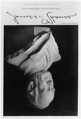
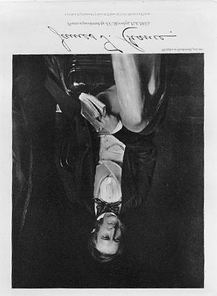
8 x PREFACE Oldbury can amply testify. His kindness of heart is shown in his generous treatment of the two thousand work people employed by his firm, and by his splendid gift of a park to the inhabitants of Smethwick and Oldbury. It would seem ungracious to withhold these facts illustrating the private life of Sir James Chance in introducing an account of his labours as a man of science, the more so that his achievements in the improvement of lighthouses were in strict consonance with his lifelong endeavours to promote the happiness and well-being of his fellow-creatures whether on sea or on land. J.K. PORTRAITS SIR JAMES T. CHANCE frontispiece From a bust by Hamo Thornycroft, R.A SIR JAMES T. CHANCE to face p. 7 From a Portrait by J. C. Horsley, 1854.
9 THE LIGHTHOUSE -WORK OF SIR JAMES CHANCE I The luminary in a modern lighthouse is caged in a complex structure of glass lenses and prisms, which collect its divergent rays and concentrate them in beams of intense power upon the horizon and upon those parts of the sea where they will be useful to the mariner. The application of the refractive properties of glass to this purpose was the work of the great French mathematician and physicist, Augustin Fresnel, early in the last century; and the splendid dioptric' instruments of today are developments from his original constructions. The story of their gradual evolution is to be found in well-known text-books on the subject; here it is only desired to leave some record of one of the most industrious and successful builders upon his foundation. 1 1 The fundamental work on the dioptric system of lighthouse illumination is Fresnel's Memoire sur un nouveau systeme d'eclairage des Phares, read before the French Academy of Sciences on July 29, 1822, and embodying two earlier communications of his to the Commission des Phares in 1819 and This was followed, when Fresnel's proposals had been thoroughly
10 2 THE LIGHTHOUSE WORK OF Scientific knowledge and technical skill of a high order are required to construct a dioptric light. The glass-founder, in the first place, must exercise his highest art to produce a colourless glass free from striae and other flaws. Roughly cast in moulds, the lenses and prisms must then have their surfaces accurately ground to particular curvatures, whose calculation is the province of a skilled mathematician. When they have received their final forms, and have been finely polished, they must be fitted into their places with the most scrupulous nicety, in order that the rays falling upon each may be transmitted exactly in the direction required. Then the plans of the engineer must be subordinated to the practical difficulties of working a highly refractory and brittle material, and to the masterful dictates of economy. He cannot employ always the same design on different occasions, but must have regard to particular local requirements, and may be called upon to invent new forms or arrangements to suit them. discussed and practically tested, by the Rapport contenant 1'exposition du systeme adopte par la Commission des Phares pour e clairer les Cotes de France, a report drawn up by Admiral de Rossel at the request of the Commissioners, and confirmed by them on September 9, Next we have Mr. Alan Stevenson's Notes on Lighthouse Illumination and Rudimentary Treatise on Lighthouses, and Lieutenant Drummond's paper On the Illumination of Lighthouses (Philosophical Transactions, vol. xxiv. 1830), general works now superseded by Mr. Thomas Stevenson's Lighthouse Illumination (2nd edit. 1871), Lighthouse Construction and Illumination (1881), and his article in the latest edition of the Encyclopaedia Britanica, and by M. Allard's Phares et Balises (1883). Also may be mentioned M. Leonce Reynaud's Memoire sur l Eclairage et le Balisage des Cotes de France (1864), Sir James Chance's papers on Optical Apparatus used in Lighthouses (1867), and Dioptric Apparatus in Lighthouses for the Electric Light (1879), Sir James Douglass's The Electric Light applied to Lighthouse Illumination (1879), and M. Allard's Memoire sur l'intensite et la portee des Phares (1876), and Memoire sur les Phares Electriques (1881). The three English papers are printed in the Minutes of Proceedings of the Institution of Civil Engineers, vols. xxvi. and Ivii., and those of Sir James Chance are, by permission of the Council of the Institution, reprinted an appendix to the present work.
11 SIR JAMES CHANCE 3 The resources of physical, mathematical, mechanical science alike are taxed in the production of these beautiful instruments. In James Timmins Chance a man was found fitted to cope at once with the mathematical and optical problems of lighthouse science, with the mechanical devices ancillary to their solution, and with the technical difficulties of glass manufacture. At Cambridge he had taken a high mathematical degree, and already as an undergraduate was a successful inventor of machinery. Endowed with natural talents and with an appetite for work which embraced not only the pursuit of science, but made him besides a classical scholar, a lawyer, and a theologian, it was the accident of his family connection that led him, on the completion of his college career, to enter the glassworks of his uncle and father at Spon Lane, near Birmingham. In Fresnel's time dioptric apparatus was produced only in France. But soon after his death the manufacture was taken up in England by Messrs. Cookson & Co., of South Shields, who constructed their first annular lens as a specimen in The earliest dioptric lights erected in these islands were made by them. 1 They were instructed by Leonor Fresnel, brother of Augustin, but they failed to surmount adequately the difficulties in their way. At first they tried to mould the lens, and then to grind it, out of one thick sheet of glass, and when they found it necessary to build it up of separate rings they did not avail themselves of Fresnel's ingenious mechanism for giving to the surfaces of the rings their proper differing curvatures, but ground them all to the same form in a spherical bowl. In It was reported to the Royal Commission on Lighthouses in 1860 that twelve British lighthouses and one Irish contained refracting apparatus made by this firm.
12 4 THE LIGHTHOUSE WORK 0F they sold their works to Messrs. R. W. Swinburne & Co., who shortly afterwards gave up the manufacture. A chief difficulty was found in the oppressive restrictions of Excise. Nothing in the form of these lenses,' Mr. Swinburne wrote to Mr. Chance in 1864, could be made in either their Crown or Plate-Glass Works without infringing the law, and an Order in Council had to be obtained to permit their manufacture. Even then the ordinary duty on plate glass [which was something like 300 percent on the cost of the glass] was charged on the lenses, and no drawback or rebate of duty was allowed upon the immense number that were defective and useless. From this cause, and from the difficulty and expense attending the infancy of the manufacture, Messrs. Cookson & Co. were never adequately remunerated. The matter was taken up with great zeal and ability by a junior member of the firm, and, as the oldest plateglass firm in England, they felt themselves impelled to attempt the establishment of a manufacture for so patriotic an object that might prove worthy of this great maritime and manufacturing country.' Messrs. Swinburne & Co. having abandoned the manufacture, for a few years it remained the monopoly of the firms of M.M. Letourneau & Lepaute, of Paris. But about 1850 Messrs. Chance Bros. & Co. determined to attempt it. They engaged the services of a French expert, M. Tabouret, who had been for thirty years in the employ of the lighthouse department of the Ponts et Chaussees, and had worked for Augustin Fresnel himself. He constructed an apparatus of the first order, which was shown at the Great Exhibition of It was a wholly dioptric fixed and revolving light - that is to say, there was a revolving drum of eight annular lenses with fixed reflecting 1 Figured in Stevenson's Lighthouse Construction and Illumination, p. 79.
13 SIR JAMES CHANCE 5 prisms above and below. The workmanship,' the Jury reported, was not characterized by any degree of finish a fact in its favour, as any great degree of finish, or adoption of ornament, would involve an increased outlay of capital without compensating advantages. 1 And the glass, having purposely been made very hard in order to resist corrosion by the atmosphere, had a greenish tinge, though as regarded striae its quality was considered to be equal to the French. The lamp was an Argand 4-wick burner, supplied with oil on the fountain ' principle. M. Tabouret retired from Spon Lane in 1853, and during the next two years Messrs. Chance were occupied in mastering the details of the work, and in gaining experience. They completed in this period seven apparatus, all for fixed lights, two of them of the third order, two of the fourth, and three of the fifth. 2 On one of these Professor Faraday, as scientific adviser to the Trinity House, reported on March 14, 1854: Having this day examined one division of a catadioptric apparatus constructed by Mr. Chance, of Birmingham, and compared it with one of French construction, which the Corporation possess, mounted in the comparative frame, I am of opinion that, in the colour of glass, the working of the various pieces, and the fitting of the whole together, the former is equal to the latter; and, from the effect of the light upon the screen, I believe that one would not be distinguishable from the other when seen at sea.' In 1855 Messrs. Chance largely increased their plant, 1 Reports of the Juries, Exhibition of 1851, p One of the third order, and one of the fourth, made for Messrs. Wilkins & Co., the well-known makers of lighthouse lamps and catoptric apparatus, were put up, I believe, at Broadhaven and at Spit Bank, in Cork Harbour. The other of the third order went to the Beeves Rock (river Shannon); the other of the fourth to Samphire Island in Tralee Bay, and one of the fifth to the Levant or the Black Sea.
14 6 THE LIGHTHOUSE WORK OF and in the same year they showed a specimen of their manufacture at the Paris Exhibition. In the next three years they constructed and sent out more than thirty dioptric instruments, erected on the coasts of Great Britain and Ireland, of the Mediterranean and Baltic Seas, of Australia, New Zealand, Vancouver, and Ceylon. They greatly improved their work as the result of experience, and their glass was no longer open to the reproach of bad colour as compared with the French. When in 1859 they made overtures to supply dioptric apparatus to the Spanish Government, the engineer, Senior Lucio del Valle, was sent to visit their works, and to report upon their capability of doing what they offered, and the following sentences are translated from his report (January 20, 1860): 'At the time of the Universal Exhibition of 1855 I had already occasion to observe at the Palais de l Industrie an apparatus constructed at the extensive glass-works which these gentlemen possess at Spon Lane, near Birmingham, and since that time they have devoted themselves with ardour to the establishment of the new workshops which the manufacture of the lights required, in order that they might compete with the French constructors and destroy their monopoly. From what I was shown there it is easy to deduce: (1) That the catadioptric lights made by these gentlemen are not inferior to the French lights as regards the optical part, judging from the official reports of competent persons, and from the attentive examination I made of the prisms and lenses from their coming out of the melting furnace to their arrangement in the apparatus. (2) Nor are they at all inferior as regards the mechanical part; they even present certain advantages over the French lights in points of detail.'
15
16 SIR JAMES CHANCE 7 II Mr. James Chance, as chief manufacturing partner, had, of course, a great deal to do both with the inception of the lighthouse works at Spon Lane and with their development. But it was only in 1859, in consequence of the appointment of a Royal Commission to inquire into the condition of the lights, buoys, and beacons of the United Kingdom, that he was led to make them the very special object of his attention. Brought into communication with the members of the Commission, his enthusiasm was kindled, and he gave up chiefly to the scientific study of lighthouse illumination the next twelve years of his life. In the present chapter I propose to give an account of his work with the Commissioners in the years 1859 to 1861, and in conjunction with them with other distinguished men, in particular with the Astronomer Royal 1 and Professor Faraday. The Commissioners held their first meeting in January, They proceeded to circulate among the various lighthouse authorities, general and local, and among a large number of merchants, mariners, manufacturers, and others, papers of questions on the subject-matter of their investigation. They then personally inspected most of the lighthouses in Great Britain and Ireland, and many in France and on the north coast of Spain, and visited 1 Professor (afterwards Sir George) Airy.
17 8 THE LIGHTHOUSE WORK OF works where lighthouse apparatus of various kinds was constructed. The condition in which they found many of the lights they visited amply justified their appointment. Even in the best cases, they said, a large proportion of the light was wasted. Sometimes a part of it was thrown too high, sometimes it shone upon the land. In some cases the fault appeared to arise from want of consideration of the requirements of the locality; in others from want of adjustment in apparatus ordered with insufficient specification by the authority giving the order, originally constructed by a manufacturer without reference to elevation, and finally placed by the authorities, without considering the construction, at an elevation for which it was not fitted.' There were also cases of faulty manufacture, of bad glass, and of inaccurate grinding. They found, first, that the dip of the sea horizon below the geometrical horizon had never, in the United Kingdom, been properly taken into account in dioptric lights; secondly, that the various parts of the dioptric apparatus had not even been adjusted to the flame and the geometrical horizon with sufficient accuracy; and thirdly, that in the English and Irish lights the flame had been kept far too low, owing to the use of three wicks only, and of the fountain-lamp.' This had the double disadvantage of diminishing the upper part of the flame, which was of the greatest service in illuminating the sea, and of lowering the section of greatest luminosity in the flame below the focus of the lens, thus causing the brightest portion of the light to be in that portion of the same which always of necessity sent its rays above the horizon.' The lamps, on the other hand, used by the Northern Commissioners (the Scottish Board) were mechanical pump-lamps producing good flames of about double the height of those in England and Ireland. And similarly in France the
18 SIR JAMES CHANCE 9 use of good flames obviated to a great extent the errors of adjustment which were found there also. 1 At that time glass for dioptric apparatus was made only at three factories - those, namely, of M. Lepaute and of MM. Sautter & Cie. (successors of M. Letourneau) at Paris, and of Messrs. Chance Brothers & Co., at Spon Lane. The Commissioners visited the first and last of these, the last on December 23, 1859, when, under the Guidance of Mr. James Chance and of M. Masselin, engineer to the firm, they made a thorough inspection of the processes employed in the manufacture of the lenses and prisms, and of the arrangements for testing their optical accuracy. 2 They had occasion to remark upon the very superior quality' of the glass, and upon the machinery, of a superior description to any yet seen,' for grinding the surfaces accurately. 3 They discussed the disadvantages of ordering different parts of an apparatus in different quarters, and of not giving to the manufacturer of the glass information as to the nature and size of the luminary to be used. Messrs. Chance stated that they were not even allowed to tender for the metal framework, although obliged to construct such for their own use in adjusting the glass. And it is clear that under this system, when the lenses and prisms came to be set up at the lighthouse in a different framework and by other hands, the 1 2 Report of the Commissioners (1861), i., ix., x, xiv. Ibid. i Fresnel contrived expressly a system of grinding the glass rings by combining a cross stroke with rotation, thus translating his geometrical conceptions into corresponding mechanism. (Mr. Chance in his paper of 1867.) The Astronomer Royal said in the discussion on this paper: He had had the advantage of seeing the beautiful mechanism in Messrs. Chance's, works, and that which struck him most was the cross-stroke in the polishing; when there was a ring lens to be made, the cross-curvature was not given by grinding in a bowl, but by the cross-work of the polisher, and by some small adjustment of the mechanism, which Mr. Chance had arranged, there was a power of altering the degree of curvature which would be given by that cross-stroke. Upon that everything depended.
19 10 THE LIGHTHOUSE WORK OF pains taken by the constructor to ensure accuracy of adjustment might be thrown away. 1 Or, as happened in some cases, an unsuitable lamp might be provided, or the bars of the lantern be placed so as to intercept some of the light. Nor could allowance be made for the dip' of the horizon. That is, and particularly in the case of a lighthouse standing high above the sea, in order to illuminate a given extent of sea up to the horizon, the direction of the rays must not be geometrically horizontal, but inclined to a given extent downwards. With the metallic catoptric mirror, the beam of light can be depressed or elevated by simply raising or lowering the position of the lamp. But with dioptric apparatus this is not possible, since the refracting and reflecting portions would be affected in opposite ways. The lenses and prisms must be designed and adjusted to this end in the first instance. But, under the conditions existing in 1859, the manufacturer of the glass received no instructions to allow for dip, the practice being to adjust the apparatus by one rule for all cases. The importance of this question caused the Commissioners to make it at once the object of their special inquiry. Early in 1860 they circulated among a few leading men of science and experts in lighthouse apparatus a set of questions intended to elicit opinion on the propriety of giving to the manufacturer of dioptric apparatus, to guide him in making his adjustments, information as to the height of the light above the sea and the horizontal arc required to be illuminated. 2 Mr. Chance was one of those consulted. In 1 Cp. Mr. Chance's remarks, p Circular No. X.; the answers to it in the Commissioners Report, ii. 589 foll. Most of those consulted agreed that the information ought to be given to the manufacturer. The conspicuous dissentient was Professor Faraday, but his answer shows that he had not yet given attention to the subject.
20 SIR JAMES CHANCE 11 a letter of March 7, 1860, Admiral Baillie-Hamilton, Chairman of the Commission, requested his 'individual and special' attention to the points of inquiry, and expressed his desire that the Astronomer Royal (of whose services the Commissioners were largely availing themselves) should go to Birmingham in order to meet him and compare views. In another letter the Admiral hoped that the Astronomer Royal and Mr. Chance would not confine themselves to a simple answer to the questions, but would go further and suggest other and perhaps more important data as necessary to be furnished to the manufacturers of an illuminating apparatus on receiving an order.' Again, on March 24, he wrote that the Commissioners particularly desire to have Mr. James Chance's answers such as he may be disposed to give - to those questions, and any additional observations or suggestions that he might be disposed to make. The interview desired took place about March 20, and on April 2 and 3 the Astronomer Royal visited Spon Lane, and made a thorough scientific examination of a large apparatus in course of construction for the Government of Victoria. He found the individual prisms to be all properly curved and all well adjusted, and he could not say that one was better than another. 'Each panel of prisms that I examined appeared excellent.' But the lamp, or the flame, was too low. We raised the lamp pillars five sixteenths of an inch, and all was then right. During, this time the lamp flame had been, as I understand, at the full English height, not at the full French height. When the lamp flame was lowered, the faults exhibited themselves again. The height of the lamp-stand had been adjusted by the engineer s usual rule.' No light-frame, the Astronomer royal believed, had
21 12 THE LIGHTHOUSE WORK OF ever been examined so well before, and he gathered from this examination the following points: - 1. The general excellence of the system of grinding the prisms, and arranging them in each frame, by the operations in Messrs. Chance s long gallery. 2. The necessity for another examination when all the frames are united. 3. The importance of not being bound by such a rule as had been adopted by the engineer. My observations show the importance of attending more carefully to height of lamp than has yet been done, and show that in the use of small sources (as the galvanic spark) it will be extremely important to be assured that the height is always the same. I have written to Faraday to ask him whether he is certain of this constancy of height. After this I examined carefully (in the day) the mathematical process on which is founded the experimental process by which the curvature of the curved reflecting side is examined. It appears quite correct. Subsequently I saw the testing of one of the external rings of a lens in the long gallery. This was going on as a matter of daily manufacture, and was not put up for my edification. It was excellent. I had no idea that a ring could be ground to do its duty with so much accuracy.' GENERAL INFERENCE. At present, the great excellence of a lighthouse is or may be the optician's part. The great defect and waste is in the source of light. 1 The Astronomer Royal wrote also to Professor Faraday 1 Letter to Admiral Hamilton, Commissioners' Report, i. 77.
22 SIR JAMES CHANCE 13 about what he had done at Spon Lane, and the latter, as in a measure responsible for the light on behalf of the Trinity House, wrote to Mr. Chance about it. Mr. Chance replied that he had not, after all, raised the burner, but had made a slight change in the setting of the lower prisms. He pointed out that the proper position of the focal plane in the flame was by no means decided, and that it was a very important matter for investigation. During the next two months the Commissioners and their Secretary, Mr. J. F. Campbell, of Islay, a gentleman who had long devoted attention to optical science, and the Astronomer Royal, visited various British and French lighthouses, and among them the two at Whitby, where the apparatus was of Messrs. Chance s manufacture. The Astronomer Royal reported on them: 1 The dioptric 2 part of the apparatus is beautiful. The glass is of the best quality. The working is so perfectly true that in viewing the image of the horizon, and moving the eye so that it (the image) is shifted from the broad central band successively to the narrower lateral bands, there is no perceptible jump or indistinctness, every band forming its image exactly and truly in the same place.... It is a most beautiful piece of work; possible only where the maker is a man of science and also a practical man.' The reflecting prisms he thought to be very good, but not so strikingly good.... There was some difficulty in catching the image of the line of the horizon so sharply. Still, there it was, and there was no difficulty in seeing that the boundary of light did move over the whole as it ought. But in the southern lighthouse he thought the details of the form of the reflecting prisms bad, and his impression was that they were of little use. 1 June 16, 1860, Report, i I.c. refracting.
23 14 THE LIGHTHOUSE WORK OF The adjustments to the horizon he found to be all wrong. My impression is,' he wrote, that in the north lighthouse three-fourths of the light is absolutely thrown away, and in the south lighthouse nine-tenths of the light is absolutely thrown away... When, with a ruler, I covered the part of the flame which merely gave light to the sky, it was absurd to see how little was left for the useful part... It really gave me a feeling of melancholy to see the results of such exquisite workmanship entirely annihilated by subsequent faults in the mounting and adjustment.' Largrer flames, he thought, would only partially remedy the evil. If the burners were raised, the efficiency of the refracting portions would indeed be increased, but that of the reflecting prisms would be diminished. Readjustment was necessary. He expressed the hope that, while the state of these lights must be made public, this should be done in such a way as to throw no blame on Messrs. Chance, whose workmanship, as shown in the glass, was admirable, or upon the engineer's work in the framing and mounting, which appeared to be of the highest order. The necessary statement should be made in such a shape as would prevent the commission of any injustice or the excitement of any painful feeling.' On June 24, with Admiral Hamilton's consent, he wrote to Mr. Chance about his examination of the Whitby lights, expressing his desire that he also, or an agent whom he could trust, should examine them, and inquiring whether, if the consent of the Trinity House were obtained, he would enter into the question of readjusting the apparatus. Again he wrote on June 28: I conjecture that a rule of adjustment was laid down in the first instance - in France, I suppose - which has been closely followed everywhere, and that that rule is wrong.
24 SIR JAMES CHANCE 15 I very much wish that I could induce you to look at the Whitby lights. I think that it would lead to an extensive and beneficial revolution in lighthouses.' The next day he wrote to Admiral Hamilton: I enclose a letter which I have just received from Mr. Chance. It is clear, I think, that by judicious cooperation with him we may do much to improve the lighthouses.... Now, what in your judgment would be the best way for bring together the Trinity Board, and Mr. Chance, and ourselves, for the improvement of the Whitby lights? 1 And again on July 4: 1. The Whitby light is the most flagrant instance of mismanagement. 2. The constructor of every part of the Whitby apparatus is at hand. 3. The said constructor is willing to go heartily into the improvement of the Whitby light. Therefore, leave all others and rest on it.' And to Mr. Chance he wrote on July 2: I have spoken to Admiral Hamilton about our wish to arrange with the Trinity House for putting those noble machines at Whitby into their just condition, and expect daily to hear from him.' On July 5, Admiral Hamilton, Dr. Gladstone, F.R.S., one of the Commissioners, the Astronomer Royal, and Mr. Chance, met at Blackheath. 2 The third named stated that he and Mr. Chance were agreed upon the best method of remedying the defects at Whitby, which was to lower the burner to suit the position of the reflecting prisms, and to lower the refracting zones to suit the new position of the 1 Report, i Ibid, i. 52
25 16 THE LIGHTHOUSE WORK OF burner, cutting off the lowest of them as might be necessary, and adding to them at the top if required. After some conversation, a letter was prepared inviting the Elder Brethren of the Trinity House to meet the Commissioners and others at the North Foreland and Whitby lighthouses some time in the month of August. In the meantime (April 1860), Captain Ryder, R.N., another of the Commissioners, had entered into a correspondence with Mr. Chance about particular points connected with the elevation of lighthouses above the sea. Supposing, he asked, an order to be sent for a series of dioptric lights to be placed at heights above the sea varying from 100 to 500 feet, what difference would be made for each 100 feet in the adjustment of the lamp and the several panels, and in the initial angles given to the prisms? Further, supposing that the heights had not been specified, and the lights all made alike, what loss of light would there be in each case for each 100 feet of elevation? Mr. Chance replied that the adaptation of the apparatus to different heights could be perfectly accomplished by adjusting the lenses and prisms in the frames without altering their forms for each particular case. For the heights given, no loss of light would be observable at the horizon, but the extent of sea illuminated between the horizon and the lighthouse would be lessened in proportion to the square root of the elevation of the light above the sea. To questions as to whether perfect parallelism of the rays was aimed at in adjusting the glass, or a certain amount of divergence purposely introduced, Mr. Chance replied that perfect parallelism was attempted, and that for the focal rays a close approximation to it was obtained. In further correspondence he gave details as to the particular amount of adjustment which would be required for particular variations
26 SIR JAMES CHANCE 17 in the height of a light above the sea, so that the rays from the brightest part of the flame should be directed to the horizon, and other particulars as to the extent of sea which would then be illuminated by the natural divergence of the light. He also offered to calculate and send to Captain Ryder a table showing the successive extents of sea illuminated by successive horizontal sections of the flame. Further, he suggested that to illuminate the sea quite near the lighthouse it would probably be better to arrange the lower prisms for this special purpose than to increase the divergence of the whole beam. Captain Ryder replied, thanking Mr. Chance very much for his very interesting and instructive letters, and saying that his replies would be laid before the Commissioners, and would be very useful to them. In September he wrote again for further information. He wanted calculations made, and a table drawn up, to show for every 10 feet of height from 60 to 300 feet, and for every 25 feet from 300 to 500, the angle or dip' ( ϑ ) between the geometrical and the visible horizon, the angle ( φ ) between the visible horizon and a point on the sea one nautical mile from the base of the lighthouse, the distance ( x ) on the sea from the horizon inwards covered by an angle equal to ϑ, and the distance ( y ) from the one-mile point inwards covered by an angle equal to φ. By the help of these data the Commissioners hoped to arrive at an opinion as to the limit of height of a light, after passing which the dip should be taken into consideration, also the effect at each height of neglecting to consider the dip. Also Captain Ryder wished to know in each case the heights in the flame at which lines drawn from the visible horizon and from the one mile point through the centre of the lens would cut the flame, and for the five cases of even hundreds of feet the
27 18 THE LIGHTHOUSE WORK OF additional height that would have to be given to the flame to throw direct rays on the spaces y. These lengthy calculations were made by Mr. Chance, and the results roughly corrected for atmospheric refraction; and subsequently, after correspondence on the subject with the Astronomer Royal, he made them afresh from different formulae, introducing also the true correction for atmospheric refraction, as communicated by that gentleman. The figures thus arrived at were very close to those previously calculated; and the tables and calculation were printed by the Commissioners in their Report. 1 The joint visits to the North Foreland and Whitby lighthouses having been agreed to by the Trinity House, a preliminary meeting of a deputation therefrom with the Commissioners took place on July 30. The Astronomer Royal and Professor Faraday were present, and the former made a statement of the observations made by him at various lighthouses. 2 The visit to the North Foreland came off on the date fixed, August 2. 3 The Commissioners present were Admiral Hamilton, Dr. Gladstone, and Captain Ryder, with Mr. Campbell and the Astronomer Royal; while Admiral Gordon (Deputy-Master), Captains Bayly, Close, and Weller, and Professor Faraday represented the Trinity House. They were met by Mr. Thomas Stevenson, on the part of the Commissioners of Northern Lighthouses; by representatives of the Ballast Board of Dublin; by M. Sautter, who 1 i The Astronomer Royal also had calculated the angles of dip required for distances from thirty miles down to a quarter of a mile. He sent the results to Admiral Hamilton on April 2, 1860 (Report, i. 77), and added: In reference to the wants of nautical men, ought we to be sure to provide for light at the small distances as well as at the great ones? The subject may be important if we contemplate the use of very small sources of light, as the galvanic spark. 2 Report, i Ibid. p. 55
28 SIR JAMES CHANCE 19 had made the optical apparatus; and by Mr. Wilkins, who had supplied the lamp. Mr. Chance, though invited, preferred to remain away, in a case where the apparatus was not made by his own firm. The light, a large new one, had already been examined by Admiral Hamilton and Mr. Campbell, who pronounced the apparatus to be 'very well constructed and arranged,' but, they thought, upon the usual plan, to throw a parallel beam from the centre of the flame at right angles. 1 The Astronomer Royal had reported it to be an effective light, but admitting of improvement. 2 It now appeared that a late lowering of the burner by one-eighth of an inch had improved its position with reference to the reflecting prisms, but had correspondingly injured it in reference to the refractors. The question for consideration was, whether, if a permanent alteration were decided upon, it would be better to lower the lamp still more, and the refractors to suit, or to raise the former to its old position and readjust the reflecting prisms. M. Sautter expressed himself in favour of the latter alteration, if any were required, but contended that the apparatus was properly adjusted for a proper overflow lamp, so that the best part of the flame illuminated the horizon, a contention with which Professor Faraday agreed, excepting with regard to one or two prisms. 3 At Whitby there assembled, on August 9, Admiral Hamilton, Captain Ryder, Dr. Gladstone, and Mr. Campbell, Admiral Gordon, Captains Close, Bayly, and Nisbet, Professor Faraday, and Messrs. Thomas Stevenson, Halpin, Sautter, Chance, and Masselin. Some of those present thought that, in spite of the defects which revealed themselves on inspection within the lantern, light would in reality be seen in all parts of the apparatus from the sea. 1 Report, p Ibid. p Ibid. pp. 55, 92.
29 20 THE LIGHTHOUSE WORK OF Arrangements, therefore, having been made for the keeper at the north lighthouse to cover up, at a given signal, the refracting band, so that the light thrown by the reflecting prisms might be observed alone, the party boarded the Trinity House yacht. On the outward journey it was seen, by means of a telescope, that while copious rays were proceeding from the upper reflectors, only a very faint light was visible from the lower ones. And the same thing was observed at a distance of from four to five miles from shore. Observation of the southern light on the return journey showed that of its lower reflecting prisms only the lowest were giving available light, while a dark band gave the impression that no rays were coming from the central refracting zone at all. Indeed, the well-adjusted upper reflectors of the northern light were judged to be equal in efficiency to the whole of the southern apparatus. 1 Summarizing under fifteen heads the defects of the Whitby lights, 2 the Commissioners thought proper to add to their report the following note:- It is due to Mr. James Chance to state that the orders given to him are simply to construct a certain well-known apparatus of a given size. Up to the time of the commencement of our inquiries he had not directed his mathematical researches into investigations connected with the scientific questions bearing on the subject. Mr. Chance was never informed of the height of a proposed lighthouse; and that very inferior description of lamp, the fountain, was ordered of another firm, leaving him no option in the matter.' Professor Faraday, they said, and the Elder Brethren of the Trinity House, had always disclaimed being considered opticians. They had depended on Fresnel's calculations, and supposed that adjustment after his rules was 1 Report, pp , Ibid. pp
30 SIR JAMES CHANCE 21 applicable to any height of flame and to any elevation of the lighthouse. The two examinations made clear to all the necessity of maintaining, to begin with, a good and constant flame, and then of determining what particular parts of such a flame would be most effective for sending light through the different glass agents. Captain Ryder had expressed the opinion that this question must be settled before it could be decided what was the best position of the lenses and prisms with reference to the flame. The Astronomer Royal had written on August 6: 'I intend to suggest to Mr. Chance some experiments for determining the special section of the lamp flame which will send to the horizon the most brilliant light through the reflecting prisms. 1 Professor Faraday opened a correspondence on the subject with Mr. Chance immediately on his return from Whitby. On August 13 he asked him for a fullsized sectional drawing of a dioptric apparatus, in order that he might consider for himself, in conjunction with experiments with a good lamp, the proper position of the focal points in the flame. And in a long report to the Trinity House 2 he entered upon a full discussion of the question. The burner, he pointed out, should be placed so that the widest and brightest' section of the flame should coincide with the central focal plane of the refractors. All that light, he said, which emanates below that plane, and passes through the lenticular bands, will be thrown up into the sky above the horizon, but all that emanating from the great body of flame above that plane will be cast over the sea between the horizon and the shore, doing good service to the mariner.' But, as this brightest section of the flame might vary from 1.12 in. above the burner for a high flame down to 0.75 in. 1 Report, p August 16, ibid. pp
31 22 THE LIGHTHOUSE WORK OF for a low one, it was of the first importance to provide a lamp which should keep up a flame suited to the adjustments of the glass. The lamp should have a free overflow, and in the case of a first-order light four wicks, and a chimney, glass and iron together, six feet long. As much oil as possible should be burnt without smoking, for when in a good state the light is as the oil burnt. 1 The light lost by not keeping up a good flame was all light which the refractors would have thrown upon the sea. The focal lines of the upper reflectors should pass through a bright and abundant ' part of the flame, but so as to leave as much as possible of it below them, since it would be this portion of the flame whose light would be directed upon the sea. The common focal point for the upper reflectors he considered to be best situated at 1.55 in. above the burner in its central axis. But of the light which should go to the lower reflectors, at least half, with the very best flame, would be intercepted by the burner. Their focal lines should therefore cut the flame as far forward, and up, as is consistent with its passing through a bright part' of it ; and here again it was the part of the flame below these lines which threw light upon the sea. The French practice was to select a different focus for each of the lower reflecting prisms, varying from 68 mm. (2.66 in.) above the centre of the burner for the lowest of them to 38 mm. (1.5 in.) for the highest. But all these adjustments had reference to a horizontal plane, which was of course above the direction of the sea horizon; and allowance should be made to deflect the rays below that plane. The correction for the refracting bands 1 Mr. Chance, however, in at letter of April 22, 1861, after he had worked with the new lamp to be described in Chapter III., adduced reasons for doubting the truth of this proposition; for this lamp produced an excellent flame with a diminished consumption of oil.
32 SIR JAMES CHANCE 23 would be suitably made by raising the burner; but this alteration would only increase the error for the two sets of reflecting prisms. The difficulty in their respect must be met by instructions to the maker of the apparatus at first. After his experience at the North Foreland and at Whitby, he thought that the first thing to do was to provide an excellent and constant lamp,' and that all lights of the same order should have a lamp of the same quality. Such a lamp having been provided, experiments should be made to determine what were really the best positions in the flame for the different focal points, and the apparatus be adjusted accordingly. Mr. Chance replied at length to the questions of the Astronomer Royal on August 20. After asking for explanation of his meaning on certain points, he went on, speaking of the reflecting prisms: For the lower prisms, I find by actual experiment that their respective focal sections of the flame should intersect each other in the outer flame. If this common intersection be within the outer flame, the light from the whole panel converges (and the contrary effect, I imagine, would take place if this intersection were to be outside the flame). The effect of convergence, even when the intersection was at the second flame (counting from without), was most striking.' Experimenting with some new apparatus some six weeks before, he had come to the conclusion that, supposing the foci for the lower prisms to be in the axis of the flame, the best positions for them would be: for the highest prism at 20 mm., for the next at 25 mm., and for the others at 30, 36, 42, and 49 mm. respectively above the focal plane of the lens. But he thought that his ideas might be modified by future trials and suggestions. He truly hoped and quite believed that the readjustments at Whitby would
33 24 THE LIGHTHOUSE WORK OF lead to most important results, as the Astronomer Royal had predicted. The latter replied: I am delighted that my rough sketch of the lamp-flame is working as I wished it to work - that is, inducing you to make something better. He went on to reply to the several points in Mr. Chance s letter, and ended by noticing the apparent inefficiency of English lamps as compared with the French. After the examination of the Whitby lights, Admiral Hamilton had requested Mr. Chance to write to the Trinity House, suggesting the alterations which he thought should be made there. And Professor Faraday advised in his report cited that, as maker of the apparatus, and as one who understood every point in the matter, Mr. Chance should be instructed to alter the adjustments of the southern light, the northern being left as a standard of comparison, providing in particular the best lamp possible, with a glass chimney of the proper shape, 1 and with adequate provision for draught. Soon afterwards he visited Spon Lane, and worked for two days with Mr. Chance on the determination of focal points. In one of two large lights under construction for Russia he found that Mr. Chance had of his own judgment and experience adjusted the prisms to unusual foci, the effect of which was very excellent. Those calculated for the lower reflecting prisms were, in effect, coincident with those determined by himself. But for the upper prisms their results differed considerably, and before recommending his conclusions to the Trinity House he should desire to experiment upon a whole panel of them. 2 Meanwhile, Messrs. Chance had written formally to the Trinity House, requesting to be allowed at once to make 1 Chimneys of the French type, with sloping shoulders, had been indeed supplied by Messrs. Chance, but they were not in use. Report, p Ibid. P. 92.
34 SIR JAMES CHANCE 25 alterations at Whitby south lighthouse. They explained what they proposed to do, and requested leave to supply a lamp of their own. They felt that they were not responsible for the defects of the light, and would take the greatest interest in rendering it as perfect as possible. The Trinity House, in reply, desired that the experiments proposed by Professor Faraday should first be made; and they requested Messrs. Chance to put up for his use at their works a panel such as he desired. He wrote at length to Mr. Chance on September 4 about the details of the proposed experiments. Shortly afterwards he again visited Spon Lane, and made the desired observations, and in subsequent correspondence settled what was to be the method of procedure at Whitby. 1 The necessary authority for these alterations having been sent, Mr. Chance proceeded thither with him at once, so that the work was finished early in October. Professor Faraday observed in connection therewith: 2 All the time we were at Whitby (eight or nine days) Mr. Chance and myself were occupied in learning, practising new methods of adjustment and correction, and using new instruments; and I cannot say too much in thanking Mr. Chance for the earnest and intelligent manner in which he has wrought with me in the experiments, working and thinking every point out. The method of adjustment is now so perfect, that the authorities can hardly require more accuracy than the manufacture can ensure. The Trinity House may direct at its pleasure that the light of one part of an apparatus shall be thrown chiefly in one direction, as the sea horizon, and that of another part in another relative direction, as nearer to the coast, and I have no doubt that, if the electric light or any other of the compressed intense illuminations be hereafter adopted, the 1 Report, p Ibid. pp. 93, 94.
35 26 THE LIGHTHOUSE WORK OF principles and methods of adjustment now devised and carried into practice will prove of very great and special advantage.' The adjustments were made by the method of internal observation, that is, by looking at the horizon through each lens and prism in turn from within the apparatus. It was not new, but disused, 1 and had been revived in the course of the work of the Commission. Mr. Campbell, referring, to his own employment of it, spoke of it as nothing but a return to first principles. 2 The Astronomer Royal used it when examining the light at Cap d'ailly. 3 After the alterations at Whitby, he wrote to Mr. Chance (October 27): I am quite delighted with your letter of the 26th, and with the kind heartiness with which you enter into the method of internal lighthouse-testing. I am amused when I look back at the history, in my own mind, of the introduction of this simple process. First I thought of throwing the light upon posts (as in your factory yard), and discovered that in the ordinary circumstances of lighthouses this could not be done. Then I thought of forming images in the manner of a camera obscura, and actually provided myself with opaque black cloth to stop out all the glasses but one at a time. Last came the simple notion of merely looking with the eyes. Simplicity always comes last.' 1 The usual practice at Spon Lane had been to place a white ball or a minute gas-flame in an assumed conjugate focus of a lens or prism, and the eye of an observer in the other conjugate focus at a short distance outside. The whole apparatus was tested in like manner, and the difference between the conjugate focus for the distance and the focus for parallel rays was calculated.' At the works of MM. Sautter et Cie. the upper reflecting prisms were set by looking, from the outside along a spirit-level at the centre of each prism in turn, and at the reflected image of a red ball suspended in the contre of the apparatus, and reflected by the prism.' Report, ii Ibid. ii He enters there into a full disquisition on the method. 3 Ibid. i. 86. Cp. p. 121 of the present work
36 SIR JAMES CHANCE 27 The method was perfected by Mr. Chance at Whitby by a discovery which rendered it unnecessary to observe the horizon itself, and enabled the final adjustments to be made at the manufactory. The horizon being obscured during several days by haze, he fixed a vertical staff upon the cliff, and took the line of the horizon upon it, graduating it to correspond with the different parts of the apparatus above and below the middle refracting zone. But this could equally well be done, by calculation, at the manufactory; on trial there, the method was found to ensure perfect accuracy, and it has been in use ever since. 1 The experimental arrangements at Whitby south lighthouse were inspected by the Commissioners and by a deputation of the Trinity House on October 12 and 13. There were four equal octants, each with refracting zones and upper and lower reflecting prisms complete. For the refracting portions of all the four the French focus, 28 mm. above the burner, was chosen, but for the reflecting prisms different ones in each case, those in the third panel representing the French practice, and those in the second what Professor Faraday had expected to be a best if not the best arrangement.' A good four-wick lamp had been provided; it had a plentiful overflow, and was working well. The whole apparatus was mounted on a revolving platform, so that any of the panels in turn could be observed from a ship at sea. 2 When they were so observed, it was seen that No. 3 panel was inferior to the others at short distances, and even at a great distance was never more effective than Nos. 1 and 2; and the difference was greater when the refractive bands were screened off and only the 1 See Mr. Chance s own description of this, p A full account of the adjustments by Professor Faraday in the Commissioners Report, i. 93.
37 28 THE LIGHTHOUSE WORK OF light from the reflecting prisms seen. The observations were the more accurate in consequence of the standard of comparison afforded by the constant light in the north lighthouse. In the end, it was agreed that the best light was given by No. 2 panel. And whereas, before, the northern light had been somewhat superior to the southern, there was now hardly any difference perceptible at the greatest distance reached, while at a few miles' distance it was manifestly inferior. 1 After this the Trinity House decided to effect permanent alterations at Whitby south lighthouse, and instructed Mr. Chance to proceed with them at once. He accordingly went thither early in November, and was able to send in his report of work done, through Professor Faraday, on the 17th. The latter, in forwarding it, wrote: 2 'The adjustment of this lighthouse has been completed by Mr. James Chance according to the instructions received from the Trinity House: the lenticular part from a common focus 27 or 28 mm. above the burner, the upper reflectors from a common focus 28 mm. up and 30 aside, and the lower reflectors from a common focus 25 mm. up and 40 aside; the mean ray being sent to the sea horizon. The only exception is in the north lenticular panel, the sea horizon focus of which is 25 mm. above the burner. The present condition of the experimental investigation makes me not sorry for this circumstance I have not seen the lighthouse since the adjustments were made, but they were made by Mr. James Chance himself, and I have the fullest trust in him. I enclose his report. 3 Everything thus far confirms me in the opinion 1 Report, pp. 59, Printed ibid. 2 Ibid. p. 94.
38 SIR JAMES CHANCE 29 that what the Trinity House has done in this case has been done well; that every future case can be considered in relation to the adjustments necessary for it from the very beginning; and that that adjustment can be carried out with certainly.' But that the proper focus for the refractors was at 28 mm. above the burner, Professor Faraday and Mr. Chance were by no means satisfied. In reference to the north panel mentioned, the latter wrote (loc. Cit.): I doubt not that this last panel is better placed for sending the brightest light to the sea horizon than the other three (though not intentionally).' It was decided to carry out experiments on the point at Spon Lane, and on November 21 Mr. Chance wrote to Professor Faraday: 'I have, in repeated experiments, tried what positions of the refractive bands composing a lenticular panel will send the brightest light in a given direction compatible with a divergence downwards. I have not yet had a panel constructed to show the total effect, because it is important that you and I should first agree upon the approximate arrangement, inasmuch as the lenticular zones can be fixed only once for all, not being individually independent like the reflecting prisms. I have already mentioned that I find 21 to 23 mm. a good position above the burner for the focus of the middle belt. As, however, 24 mm. suits all the zones above the middle one, I propose that a point in the axis 24 mm. above the burner shall be that through which shall pass the focal lines (i.e. through the middle of each lens) of all the zones from the middle one upwards. This agrees very well with your own diagram, confirmed, however, by experiments as to the actual brightest light the respective foci being observed subsequently. In regard to the lower zones below the middle one, I recommend the
39 30 THE LIGHTHOUSE WORK OF common focal point to be 12 mm. above the burner, and 33 mm. in front of the axis' (which gave foci in the axis at from 18 to 28 mm. above the burner). Professor Faraday in his reply said: You will evidently obtain more light for the sea by the lower zones, but a very chief point is the maximum light for the horizon;' and, the panel having been set up, he came to Spon Lane and worked there for three days with Mr. Chance. He reported the results to the Trinity House as follows: 1 We found that the best focal point for the middle or chief rib [of the refracting zones, namely, of a fixed light] was 20 mm. above the burner at the axis; that the upper ribs, though varying one from another, might have the same point of 20 mm. taken for their average or common focus; and that the lower ribs required much higher focal points in the axis, varying from about 18 to 30 mm. above the burner, all of which might be referred to a common focus 11 mm. up and 36 mm. aside towards the panel. Supposing that these numbers (or any other) were determined upon, then the possibility of adjusting the parts of the panel to each other came to be considered; without which possibility it would not be right for the authorities to require that a finished panel should be subjected to examination by the focimeter in relation to such given points. The ribs of a lenticular panel cannot be adjusted to each other by any rotation of them on a horizontal axis, as is the case with the ribs of a reflector panel, but only by elevation or depression in respect of each other; and now Mr. Chance proceeded to show me how, by ascertaining the best focal point for each rib and their relation to the focal point of the great central rib, he ascertained how much they were in error; and then what proportion of 1 Report, P. 95.
40 SIR JAMES CHANCE 31 glass would require to be removed from the broad bearing surface of this or that rib to bring the whole into nearest approximation to the desired position. This he carried into effect with the panel which we had had under examination, and which had been constructed in the ordinary way, and without any particular view to such a correction; and the consequence was that a panel was produced which, when set up with the focimeter upon the burner at the numbers given above, and a small flame upon the distant (107 feet) dead level for each rib, gave a perfect practical result.... When the great lamp was lighted the effect was in accordance with the expected result. The coincidence of all the rays in one common maximum could only be observed at a great distance - i.e. at the dead level horizon; but each rib could be examined for itself and for the dead level of that rib. It must be thoroughly understood that the focal numbers have relation to the flame of the great lamp. The higher and more powerful the flame, the greater height should the focal distances be above the burner; but even with a very high flame we do not find that the focal point of the middle and upper ribs can be raised higher than 23 or 24 mm. above the burner without sending the brightest light to the sky Perhaps it may be agreeable to the Trinity House to be informed that the changes proposed now and formerly are all in accordance with observations made by the Astronomer Royal at Messrs. Chance's in the beginning of the year, and which he communicated to me personally in April last. On November 10 the Astronomer Royal addressed to Admiral Hamilton a long letter dealing principally with the subject of lighthouse management and illumination. 32 THE LIGHTHOUSE WORK OF
41 It appeared to him, he said, that there was no person officially connected with the Trinity House who was distinctly responsible either for the correct construction and erection of the illuminating parts of lighthouses with reference to their optical effect, or for the continual maintenance of those parts in proper adjustment. He thought it absolutely necessary that an officer, whom he would call the 'Optical Engineer,' should be appointed, whose special duty it would be to construct and maintain in order the whole of a lighthouse apparatus and its accessories. Such a person should be a trained mechanical engineer, and, further, be acquainted with the science of optics in a form which was rather unusual, and which none but a trained mathematician could master, involving, as it did, the understanding of the effect of different curvatures of a surface in different planes normal to the surface, receiving rays of light incident at high angles of incidence.' He should also know something of glass-making, and be perfectly familiar with the different kinds of lamps, as well as with other possible sources of illumination. Such an officer would be in a position to lay down rules for constructors of lighthouse apparatus, and to receive their suggestions; to devise special arrangements for particular local conditions; and, of course, to see that his arrangements were properly carried out, a duty for which there appears to be, at present, no provision whatever.' The principal part of his duty, to begin with, would be to examine into the efficiency of the existing lighthouses, and to report what alterations were necessary. 1 The experiments were continued at Spon Lane on 1 Report, i The remainder of the letter was occupied with certain considerations on illumination by dioptric apparatus, and by small sources of light, such as the electric spark.
42 SIR JAMES CHANCE 33 December 3 and 4, in the presence of Captain Ryder, Dr. Gladstone, Mr. Campbell, and the Astronomer Royal, and on the second day of Mr. Thomas Stevenson. Their course had been arranged by Mr. Chance and approved by Professor Faraday. The object was to apply to the lenses the same principle of rigorous adjustment which had already been applied with success to the reflecting portions of the apparatus.' On the first evening the height of the brightest point of flame above the metals was from 21 to 22 mm.; certainly not more than 22.' Next day, with a flame about 3/4 inch higher, a good French height, the brightest part of the flame was found to be at 23 or 24 mm. above the burner. It was definitely established that the section of maximum brightness in a flame rises as the height of the flame is increased, and that it is confined within very narrow limits. 1 These experiments did not settle the questions they were only designed to elucidate. Mr. Campbell, for instance, criticized the results adversely. 2 But dissentients whose opinion carried greater weight were the Messrs. Stevenson. These gentlemen were the leading experts in the kingdom in all matters relating to lighthouses, and had introduced most of the improvements in dioptric apparatus since Fresnel's time. It was their practice, as Engineers to the Commissioners of Northern Lighthouses, to carefully inspect and test all the apparatus ordered by them both before it left the workshop, and when it was erected in the lighthouse, and to make observations on it from the sea at various distances and in various azimuths, in order that any imperfection might be detected and remedied. In consequence the Royal Commissioners had found the lights in Scotland to be far superior on the whole to those in 1 Account of the experiments, Report, pp. 61, 62, Ibid. ii. 627.
43 34 THE LIGHTHOUSE WORK OF England and Ireland. 1 The views of the Messrs. Stevenson on the subject of adjustment were supported by the results of experiments made in July 1860 by themselves. 2 Mr. Chance wrote fully to Mr. Thomas Stevenson on the points which had been raised, and on the same day (December 1) Mr. Stevenson wrote to him, reminding him of certain precautions to be observed. These were - (l) to be sure of the accuracy of the lens itself as tested by the solar rays, (2) to make the observations at a sufficient distance, to avoid the risk of convergence of the rays arising from imperfections in the instrument,' (3) to use photometric tests, and (4) to be careful that the flame was of full size. He went on to describe his improved photometer and the use to which it might be put in comparing the powers of Scotch and English lights. But that he was influenced by what he saw at Spon Lane was shown by the fact that he consented (December 6) to the adjustment of an apparatus then under construction there for Mac Arthur's Head in the manner Mr. Chance proposed, though previously (November 17) he had desired it to be adjusted in the usual way. On December 29 he stated his belief that Fresnel in his experiments had used a higher flame than Mr. Chance had done, and that he intended to repeat his previous experiments. Mr. Chance, on the other hand, as he wrote to Captain Ryder on January 23, 1861, felt somewhat certain that the 28 mm. focus was chosen in order to accommodate the bottom of the refractor; and that the best positions of the foci constitute quite an undetermined question.' Messrs. Stevenson reported the results of their fresh 1 Thus we find the Astronomer Royal reporting on the light at Girdleness as the best that he had seen (October 10, 1860, Report, i. 86). 2 Ibid. p. 102.
44 SIR JAMES CHANCE 35 experiments to the Commissioners of Northern Lighthouses in February Instead of an annular lens as before, they had used, as had been done at Spon Lane, the cylindric refracting band of a fixed light. The experiments were most carefully conducted with photometers and other scientific appliances, a fourwick mechanical lamp being used, similar in all respects to those in use in the Northern lighthouses. The results confirmed those obtained before. The photometrical determinations showed that, with the burner placed at the French standard height of 28 mm. below the centre of the refractor, the most powerful part of the beam was thrown below the principal axis or earth's tangent, and that above that line the light lost power somewhat suddenly. With flames of the height and form customary in the Northern lighthouses there did not appear to be any necessity, even for the highest station in Scotland, to raise the burner above its standard position. In fine, Messrs. Stevenson thought that the difference between the results of the Birmingham and Edinburgh experiments might be accounted for by the smaller flame used in the former. Mr. Chance, however, dissented from this view. He observed that the position of the most effective part of the flame, as determined at Edinburgh, was at least half an inch above that ascertained at Birmingham with the maximum height of flame then attainable.' In a first-order light lately finished, the sea-horizon focus had designedly been placed in a part of the flame 15 mm. below that which the Edinburgh results would assign as the brightest part. This discrepancy could not be wholly explained by the difference of lamps and lamp-flames. It was of fundamental importance to adopt measures without delay to explain satisfactorily the reason of the experimental differences. 2 1 Report, p Ibid.
45 36 THE LIGHTHOUSE WORK OF Soon after this the Mac Arthur's Head light was finally examined in position. The results, Mr. Stevenson wrote to Mr. Chance (April 24, 1861), are satisfactory as to the correctness of the assumption you made, as far as they go.' With a three-wick burner substituted for one of two wicks first employed, the observations all tended to show the height selected to be on the whole the most favourable.' In Chapter IV. I shall give the focal positions selected for the different parts of the apparatus in Mr. Chance's readjustment of old lights and construction of new ones in the years 1861 to In work done for the Northern Commissioners he followed the directions of the Messrs. Stevenson, in other cases the conclusions arrived at as described. The later practice with oil-lamps has been defined by Mr. Thomas Stevenson as follows: 1 The brightest horizontal sections of the flames of the different orders of lamps have been found by short exposed photographs to be as follows : One-wick lamp, 14 mm. above the top of burner. Two-wick lamp, 19 mm. Three-wick lamp, 23 mm. Four-wick lamp, 25 mm. These points are placed in the sea-horizon focus of the central or refracting portions of this apparatus. The upper prisms are ground and set so as to bring the seahorizon to a focus for four-wick burners at a point 30 mm. above the burner and 9 mm. behind the axis, and the lower prisms to a point 18 mm. above the burner and 38 mm. before the axis; in this way the brightest sections of the flame are sent to the horizon, and the bulk of the light is spread over the sea between the horizon and the lighthouse. 1 Lighthouse Construction and Illumination, p. 235.
46 SIR JAMES CHANCE 37 These figures for three-wick burners are 29, 12, 17, and 23 respectively. Upon the question of dipping' the light to the horizon, and in reference to the work done in 1860, Mr. Stevenson goes on to say: Since then the strongest beam has been invariably dipped to the horizon. In January 1861 Mr. Chance sent in to the Royal Commissioners a paper 1 on the whole question of the adjustment of dioptric apparatus, including in it the extended reply they had requested of him to their circular of the previous year. He explained how, before the experiments and experience of the intervening period, he had assumed that the respective foci of the refracting and reflecting portions of a dioptric apparatus had been placed in the best positions in relation to the flame and the burner, and that the only question which depended upon the elevation of the apparatus was whether or not those foci should by adjustment be made to become in all or some cases the sea-horizon foci.' He had been justified in this assumption by the sanction of long usage, combined with the highest scientific authority in the first instance.' But no one could inspect an apparatus adjusted according to the received focal arrangements without being struck by the large proportion of light which was thrown above the level direction, and still more so above the sea-horizon direction, both by the reflecting prisms and refracting lens. It was urged in explanation that the customary focal adjustments, although they might cause the diversion of so much light upwards, were the best ones for transmitting the beams from the most effective sections of the flame in the direction of the sea-horizon.' But the Astronomer Royal made experiments at Spon Lane and elsewhere, in consequence of which he (Mr. Chance), 1 Report, i THE LIGHTHOUSE WORK OF
47 in completing some first-order apparatus for the Russian Government, besides allowing for the dip of the horizon, had departed considerably from the accustomed rules, as far as concerned the sea-horizon foci of the upper and lower reflecting prisms; the chief change being made in the adjustment of the lower ones, whose foci he raised 10 to 12 mm. above the customary position. Then came the experiments of Professor Faraday and himself, first at Whitby and then at Spon Lane, upon the adjustment of the refracting portions of a fixed dioptric apparatus; and he might safely assert that they had raised doubts on the correctness of the received opinions on this subject. They confirmed the previous observations of the Astronomer Royal. The primary problem was to determine the best positions in the flame of the seahorizon foci of the refracting portion and of the two reflecting portions respectively of the apparatus, and whether these positions are to be constant for all elevations of the lantern, and for all the peculiarities of different localities, or not. He himself took for granted that every portion of the apparatus should, in all cases, be adjusted in reference to the sea-horizon direction, and not the level direction,' a matter quite essential for the refractors and the lower reflecting prisms. The first questions which the manufacturer would wish to have answered, before proceeding with any adjustments, would be, what were the special requirements of the locality; whether it was desired to send the most effective light to the furthest distance, though the light nearer shore might be thereby diminished, or to illuminate the sea up to a moderate distance from the lighthouse, at the cost, it might be, of a slight diminution of brilliancy at and beyond the horizon; and whether, in the case of a fixed light, within certain points of the compass the furthest range of visibility must
48 SIR JAMES CHANCE 39 be chiefly provided for, while within other angles of the horizontal arc to be lighted the part of the sea near to shore should have its share of illumination.' He then went on to discuss separately the proper position of the foci of the refracting and the two reflecting portions of the apparatus. The value of his remarks on this subject renders it advisable to quote them in full: I. Lower Reflectors. - The position of these zones in relation to the burner, which intercepts from them a large portion of the flame, confines their vertical divergence within so narrow a range that if they were adjusted with reference to the illumination of the sea near to shore the sea-horizon would, in all cases except those of a low elevation, receive either no light at all, or only a very faint one. The best use, therefore, which can be made of the lower reflectors is to transmit to the sea-horizon the light from the most brilliant parts of the flame which correspond with the respective zones. These parts lie within narrow limits, which evidently change their position according to the height of the flame. The only practical way is to choose such a height of flame as is likely to be actually maintained, and then to place the sea-horizon foci at the greatest distances above the burner which are compatible with the most effective illumination of the sea-horizon by each of the reflectors respectively. The choice of these foci may vary slightly with the differences of optical judgment of different persons; but, whatever positions of the foci may be determined upon, it is evident that all adjustments of these lower reflectors must be made to the sea-horizon direction. II. The Reflectors. - The main point, especially in the case of a fixed light, is to determine the brightest sections of the flame corresponding with the middle belt
49 40 THE LIGHTHOUSE WORK OF and all the other refracting bands above and below respectively; and then so to adjust these various refracting parts in relation to the burner that their respective sea-horizon foci shall be placed in the corresponding brightest sections of the flame. These focal positions can only be obtained by experiment, and they will vary with the height of the flame and the optical judgment of the observer; but the limits of variation are confined within the height of only a few millimeters. One thing, however, is quite certain, that the sea-horizon foci must not be placed below the corresponding brightest parts of the flame for the sake of increasing the vertical divergence below the seahorizon direction, for that increment would be very small, whereas the loss of light at the horizon would be considerable. The importance of accuracy of adjustment to the sea-horizon, both of the refractors and of the lower reflectors, is enhanced by the consideration that the same parts of the flame, within a narrow range (not exceeding one quarter of an inch even for a high elevation, such as that of 500 feet), which illuminate the sea-horizon, also illuminate about three-fourths of the whole distance from the sea-horizon to the base of the tower. In reference to this important consideration it may be useful to remark that an angle of vertical divergence equal to one-fourth of the dip of the horizon illuminates one half of the whole distance from the horizon to the tower; and that an angle of vertical divergence equal to the dip of the horizon illuminates nearly three fourths of that distance (accurately 0.732). To show, on the other hand, how little is gained by increased vertical divergence at the sacrifice of brilliancy at the horizon, it may be added that an angle of vertical divergence, also equal to the dip of the horizon, illuminates only a small fraction of a mile SIR JAMES CHANCE 41
50 as we approach within one or two miles or so from the tower. III. Upper Reflectors. - It is in this portion of a dioptric apparatus, and generally in this only, that it is feasible to provide for the illumination of the sea towards land by a corresponding adjustment of the seahorizon foci, without any serious diminution of the light received by the distant sea. This circumstance arises from the relative positions of the flame and of the reflecting zones, by which there is a considerable range due to the breadth of the flame for illuminating the sea-horizon effectively, and yet for providing a large angle of vertical divergence below the seahorizon direction. Undoubtedly there are certain oblique sections of the flame which would produce, through the respective reflecting zones, the maximum intensity of illumination in the direction of the horizon; and, in cases where the distant sea alone has to be provided for, the sea-horizon foci of the upper reflectors should be placed in those sections respectively. Generally, however, a slight diminution of light at the horizon will be admissible for the sake of illuminating the parts of the sea near to the tower, and in such cases the positions of the sea-horizon foci in relation to the burner must depend in some degree on the intended elevation of the apparatus above the sea. Suppose, for example, that light were required up to one nautical mile in each of the two instances of elevations of 150 feet and 250 feet respectively. The requisite angle of vertical divergence from the seahorizon direction downwards would in the former case be ", whereas in the latter one it would be 2 6' 15", that is 53' larger. There is, of course, a limit to this angle of vertical
51 42 THE LIGHTHOUSE WORK OF divergence, and accordingly for high elevations we must be content with the light not approaching so near to the tower, the distance from the tower up to which the sea can be illuminated being nearly proportional to the height of the tower for a given size of apparatus.' Mr. Chance further remarked, in reference to any adaptation of the upper reflectors to illuminate the sea near the tower, that it might be argued that the flame should be kept sufficiently high to effect this purpose through the medium of the refractors. With this reasoning he concurred, except for the fact that the flame would certainly sometimes be allowed to get low, in which case the refractors would be useless for the purpose. The great advantage afforded by the use of the upper reflectors for this purpose was, that they would illuminate the parts of the sea near the land even when the flame was low, and would therefore serve to compensate for the non-effectiveness of the refractors in that case, as well as to increase their effectiveness when it was high. Appended to the paper was the table which Mr. Chance had prepared for Captain Ryder, and the mathematical process employed for its calculation. The table was extremely convenient, he observed, for exhibiting, in addition to the other information which it afforded, the heights in the axis of the flame which subtend at the middle of the refractors certain angles of vertical divergence. Lastly, Mr. Chance referred to the newly perfected method of adjusting apparatus by internal observation. The metallic framework having been fitted together at the manufactory exactly as it would be at its final destination, every part of the apparatus may then be adjusted to the sea-horizon direction just as accurately as if the glass were
52 SIR JAMES CHANCE 43 placed in the frames at the lighthouse itself, with a well defined sea-horizon for the object.' Immediately on receipt of the above paper, Admiral Hamilton wrote to Mr. Chance the following very complimentary letter: I was reluctant to leave this office last night without having written to think you, and to express my admiration of the paper you have supplied us with. If the time and labours of this Commission had had no other end, it would have been sufficiently answered in their having led to the earliest application of your talents and your time to a subject of the very last importance as regards the science of lighthouse illumination - to be mastered as that subject has been by you. Scientific men may be more minutely conscious than myself of all the value of your work, and at any rate it will stir the minds and mettle of many of them; but as even I am able to understand every axiom as well as the whole theory contained in your clear and complete treatise, I can yield to none in appreciating its merits, and in the feeling of satisfaction at its being thus given to the world.' In a postscript, Admiral Hamilton added: Some day, at your leisure, be so good as to let me know the time - the period - after your first interview with this Commission, at which you began to give your mind to and to experimentize upon the subjects to which your paper refers. I want to be able to show, if needs be, by an instance in your case, as in many others, that to have hurried our report - to have precipitated our work - would have been equivalent to the scamping it; and that I had good reason for constantly urging my generally repudiated maxim - that everything is to be done by delay. And in 1867, when taking, part in the discussion on
53 44 THE LIGHTHOUSE WORK OF Mr. Chance's paper on 'Optical Apparatus used in lighthouses,' Admiral Hamilton could not say how much the Royal Commissioners were indebted to Mr. Chance. The Trinity House, and others who were interested in the maritime concerns of the country, were aware how much was owing to him, and Admiral Hamilton considered himself fortunate in having been at the head of an inquiry in which the services of such a man as Mr. Chance could be made available.'
54 SIR JAMES CHANCE 45 III The proceedings narrated had established the fact that a point of main importance in lighthouse illumination was to provide a lamp of real efficiency, capable of maintaining a good and constant flame. Three types were in use: the fountain lamp, supplied with oil by gravitation from a reservoir placed at a slightly higher level than the burner; the pump lamp, in which the oil was forced into the burner by pumps actuated by clockwork; and the pressure, or moderator lamp, where the oil was forced up out of a cylinder by a weighted piston. The last two, when properly worked, gave the free overflow desired by Professor Faraday, but the first-named did not. Yet this lamp was found by the Royal Commissioners in universal use in the lighthouses of England and Ireland; and its inefficiency, especially in contrast with the French and Scotch pump lamps, struck them most forcibly. At Whitby south lighthouse, for instance, they found that the proportion of oil overflowing to that burnt was as 1 to 4, whereas in Scotland it was about 3 to 2, and in France 3 or 4 to 1. As a result, the effective flame at Whitby only attained one third of the height for which the optical apparatus had been designed; nor could a regular supply of oil be maintained by raising the reservoir, for then, said the Commissioners, the flame immediately rises, the pipes quickly become hot, the specific gravity of the oil in the
55 46 THE LIGHTHOUSE WORK OF rising branch is diminished, the influx of oil is increased with great rapidity, and the flame becomes extravagantly high, smoky, and unmanageable. 1 Besides, the Lightkeepers were instructed to keep down as much as possible the consumption of oil from motives of economy, and this, the Commissioners discovered, had led to the rejection of the pump lamp by the Trinity House; used on this principle, it had been found unsuitable. In accordance with Professor Faraday's recommendation, Messrs. Chance were commissioned to supply, as part of their alterations at Whitby south lighthouse, a pair of lamps such as would give the plentiful overflow desired. They supplied accordingly two pump lamps, which gave great satisfaction; but Mr. Chance, in his report of the alterations (November 17, 1860), stated that he proposed to send ultimately a pair of pressure lamps preferred by him as being simpler in construction. These pressure lamps were of a new type contrived by M. Masselin. In the old type, the pressure upon the piston was given by a number of small weights placed inside it. They were not only very inconvenient to get at, but it was difficult to increase or diminish their number without disturbing the equable weighting of the piston. In the new lamp the weights were outside the cylinder and underneath its centre. They were connected with the piston by metal rods passing through guide sockets outside the cylinder, and joined to other rods acting on the top of the piston. This ensured the requisite rigidity, and the weights could be easily and quickly altered. The whole construction, too, was very solid, which that of the old lamp had not been. 2 1 Report, i An account of this lamp in a paper read by M. Masselin before the Institution of Mechanical Engineers, April 24, 1862.
56 SIR JAMES CHANCE 47 Captain Ryder, anxious to have some experiments made on the efficiency of the different lamps, wrote on March 5, 1861, to Mr. Chance, requesting that M. Masselin should be allowed to assist the Commissioners in a short series of such experiments. Mr. Chance readily assented, and on the 23rd wrote to Admiral Hamilton to express his satisfaction that the Trinity House had taken up the question of lamps and lamp-flames, and to say that he was sending them a new pressure lamp which he liked extremely. On April 23 Captain Bayly reported to Mr. Chance its success. The highest, steadiest, and most compact flame was produced by No. 1 (the new lamp) with the least consumption of oil, the least and most equalised char of the wicks, and the most abundant and most regular overflow, it being at the rate of three gallons per hour. The superiority of the action of this lamp over the others is so evident that the Light Committee strongly recommend the principle to be adopted wherever a new pressure lamp may be required next. He added that the Trinity House wished to have a further trial, at which Professor Faraday should be present, and the lamps be worked by the ordinary light keepers. Captain Nisbet wrote to the same effect. Mr. Chance readily acquiescing, said that the saving of oil in the new lamp was an effect which he had not anticipated, and that it probably arose from the burner being kept very cool by the plentiful overflow, diminishing the loss of oil by volatilization. The chief recommendation of the lamp he considered to be its non-liability to derangement. The further trials, it would seem, again resulted favourably to the new lamp, and in September 1861 Mr. Chance was instructed to send two of them to Whitby. A lamp on the same principle was also placed in the St. Catherine's
57 48 THE LIGHTHOUSE WORK OF lighthouse, with the result that the keepers asked for blue spectacles. And the Trinity House was now quite alive to the importance of keeping a good overflow of oil. Captain Nisbet, at this time busily engaged on a lamp of his own on an improved hydrostatic (or fountain) principle, wrote on November 4: 'The overflow you must have.' M. Sautter also was modifying his lamps in the same direction, and in 1869 Mr. Chance was able to write: We have supplied our pressure lamps to all parts of the world, in many cases to places quite isolated, where no repair would be possible, and we have never yet heard of failure.' In fact, no further improvement was necessary, until the time that mineral oil came to be substituted for colza, and the lamps had to be modified to suit it.
58 SIR JAMES CHANCE 49 IV In 1861 the work of the Commissioners was finished, but that of Mr. Chance on lighthouse questions had but begun. Heavily burdened at the time with private business, and greatly interested in various public matters, he yet gave up to the construction and improvement of lighthouse apparatus nights as well as days at the Works, and occupied himself at home for hours together in solving the novel and intricate problems which presented themselves, and in working out the elaborate calculations required for each new design. He personally supervised every detail of the work, neglecting for it other more remunerative brunches of manufacture. With each new light produced the reputation of his firm for excellence and accuracy of work increased through his exertions, and he was acknowledged as an authority on the subject second to none. In the present chapter I propose to notice some of the principal oil-lights made under his direction in the ensuing years. The new principles of adjustment had been applied, as we have seen, in the case of the Russian light examined by Professor Faraday at Spon Lane in August 1860, and in the alterations at Whitby south lighthouse. The next apparatus to be so treated was one of the first order intended for the Smalls Rock, near Milford Haven, whose construction had been delayed at Spon Lane pending
59 50 THE LIGHTHOUSE WORK OF the results of the experiments on focal points. In consultation with Professor Faraday its adjustment was now completed, and on January 18, 1861, Mr. Chance expressed to Captain Bayly his earnest desire that some of the Trinity House Brethren should come down to inspect it. He further said: As its main adjustments are a great departure from the system hitherto recognised, and as any inferences drawn from practical results at sea would be valueless, unless the final erection at its destination is performed with perfect accuracy, I would suggest to your Board the expediency of making our firm responsible for the final erection. As the matter now stands, the responsibility of our firm closes with the examination by Professor Faraday. The light was inspected and examined on January 28, and Faraday reported on it: 1 You are aware that, in consequence of certain careful and prolonged experimental inquiries, adjustments altogether new, both as to their amount and their nature, have been determined upon, and put into practice for the first time in this apparatus. The manufacturer was instructed to adjust the various glass pieces by the following foci, the distances given being the foci distances above the burner and aside from its axis : Upper reflector bands 28 mm. up and 20 mm. aside Lower Lenticular refracting panel: Central zone and the upper ribs 21 mm. up and 0 mm. aside The lower ribs All these adjustments being to the sea-horizon. 1 Commissioners Report, i. 96.
60 SIR JAMES CHANCE 51 The apparatus has been put together by Mr. James Chance with these adjustments, and being in a proper place I had the focimeter set upon the burner, and a true sea-horizon mark placed in the distance. The whole was so true that the ray proceeding to the eye through the middle of each piece of glass passed by the focimeter at the point desired. The greatest departure was but 2 mm., and very few of these occurred. Further, the manner in which, as the apparatus revolved or the eye was moved about, the object at the horizon passed laterally from one panel to another, or vertically from one rib to another, showed the perfection of the adjustment of each individual piece by the harmony and consistency of the whole, though there were above 300 pieces of glass associated together. At night the lamp was lighted and observed from the distance; the results accorded perfectly with the anticipations. As the head was raised or lowered, each piece of glass showed its maximum effect at the place, its light coming in or going out as it should do in relation to the distant horizon; and I think that, as far as regards the system of adjustment, the power of carrying it into effect, and finally of examining its correct application, everything is proved to be practicable, and has here been realised. The essential points now are to supply a good lamp, and to provide that it be kept in good order. In relation to colour and striae, the glass was very good. Captain Bayly and Captain Nisbet were present at the examination. It is to be remembered that the adjustments made are all in reference to the large flame of a lamp having four cottons, the utmost advantage having been taken of such
61 52 THE LIGHTHOUSE WORK OF portions of the flame were visible in different directions. These adjustments would not be the most perfect for a concentrated light, such as the magnetoelectric discharge. After this came a formal request from the Trinity House (May 22, 1861), that Mr. Chance would assist in an examination which it was proposed to undertake of all the dioptric apparatus under its charge, and in the execution of any changes that might be necessary. He, willingly assented, and as a first step joined (June 10) Captains Bayly and Nesbet at Holyhead, and spent a week with them in the inspection of the Skerries and other lights on the Welsh coast. But the light first chosen for readjustment was that at the North Foreland. Requested (July 23) to examine it and to forward an estimate of the cost at which the alterations necessary to adapt it to Professor Faraday's arrangements' might be completed, Mr. Chance at once sent thither M. Masselin. He found that the apparatus was mounted in the same unsatisfactory manner as were those at Whitby -- that is, on a table supported by a single pillar. The light from one of the upper prisms and from three of the refracting zones he reported to be completely obscured by the bars of the lantern, the whole apparatus requiring to be raised 2.25 in. to correct this. The glass was a complete mass of irregular spongy sort of veins,' which he could only describe by the French word gras. The adjustments varied considerably, and the lamp was somewhat out of centre. The corrections necessary were at once undertaken by Mr. Chance himself, and the work was completed on August 8, Captains Drew and Arrow, of the Trinity House, being present. The apparatus was raised as required, and properly levelled. The lamp was placed correctly in the
62 SIR JAMES CHANCE 53 centre, and arrangements made for keeping it there. The top of the burner was placed 24.5 mm. (28 mm. less 3.5 mm. allowed for the dip of the horizon) below the central level plane of the refractors, the focus for the upper reflecting prisms was arranged at 32 mm. above the burner and 20 mm. behind its axis, and that for the lower ones at 25 mm. above the burner and 40 in front of its axis. The very next day the workmen were sent on to the South Foreland, Mr. Chance following on the 12th. The glass in the high light there, he had written, was so generally bad, that it would be better to replace it at some future time by a new apparatus than to attempt to weed out the bad prisms; only those badly broken might be now replaced. Everything here was finished by August 16, the foci chosen being the same as in the case of the North Foreland, with an allowance for dip of 5 mm. In the next three months corresponding alterations were effected at St. Catherine's, in the Isle of Wight, at Whitby North, and at St. Ann's, Milford Haven. In 1862, the low light at Orfordness, those at the Skerries and Bardsey Island, on the Welsh coast, and the high light on Lundy Island were taken in hand; in 1864 those at the Bishop Rock beyond the Scilly Isles, at the Needles, at the Eddystone, the high light at Spurn Head, and the two at Trevose Head; and in August 1865 that at the Bishop Rock. All these, excepting the Eddystone, were of the first order. In the six last-named of this order the focus for the upper reflecting prisms was taken at 15 mm. instead of at 20 mm. behind the axis of the burner, the other adjustments being the same as before. In the case of the Eddystone second order light the burner was placed 24 mm. (26 mm. less 2 mm. allowance for dip) below the central plane, and the foci chosen for the upper and lower reflecting prisms were
63 54 THE LIGHTHOUSE WORK OF respectively 32 mm. up and 10 mm. behind the axis, and 20 mm. up and 33 mm. before the axis. Ten Irish lights also were readjusted. 1 The best that was possible was done with all; but while one or two, as St. Ann s and the Eddystone, required little more than levelling, 2 in many cases the faults due to erroneous surface-curvatures, to defects in the glass, and to want of solidity and accuracy in the fitting together of the panels, could only have been properly corrected by entire reconstruction. In the spring of 1862 Mr. Chance was consulted by the Trinity House upon a light proposed for the Hanois Rocks, in Guernsey. This was to be a revolving red light of the first order showing a duration of flash in the proportion of 1 to 3 or 4 to the intervals of darkness, and it was proposed to attain this object by making it 12-sided, with beams diverging 6 to 7 in azimuth. Professor Faraday wrote on April 1 to Mr. Chance about the practicability of this arrangement, and the mode of producing the red colour; whether by screens outside the apparatus, or by a red globe or chimney, or otherwise. Mr. Chance thought that there was no difficulty in making a 12-sided light, but that it would cost much more than the usual 8-sided ones, in consequence of the increase in the number of panels and the inconvenient lengths which would be required for the prisms; to obtain which much 1 On May 3, 1869, Mr. Chance wrote to Mr. Graves, who had been a member of the Royal Commission on Lighthouses: 'We Have readjusted seventeen sea-lights in England and ten in Ireland since your Commission first brought attention to the subject: all these were done in 1861, 1862, and Twenty of these twenty-seven lights were of French manufacture.' The Irish lights included those at Fastnet, Kinsale Old Head, Ballycottin, Youghal, Minehead, and Dungarvan. 2 Mr. Chance to Captain Arrow, October 3, He laid the main blame in these cases upon the dioptric apparatus having been the work of one person, the framework and the erection of the whole that of others.
64 SIR JAMES CHANCE 55 glass would be cut to waste, and many special arrangements have to be made. It might be possible, he said, to obtain the required proportion between the intervals of light, and darkness by keeping the 8-sided arrangement and increasing the horizontal divergence of the beams, but no such plan (keeping the vertical divergence the same) had yet been carried into effect. As to the red colour, if panes of ruby glass were used, they should be placed just outside the apparatus, according to the usual practice, rather than inside it, or against the glass of the lantern. A ruby globe would be require to be at least two feet across, and would be very expensive, brittle, and inconvenient in use. Ruby chimneys also were expensive, and their annual cost for repairs would very likely exceed the first cost of the ruby panes. But they were already in use in Scotland and offered the simplest expedient, and the one which caused the least loss optically. Eventually this light was constructed (1862) with 16 sides or panels ' and showing flashes at intervals of 45 seconds. To produce the red colour a ruby-glass chimney was used. The lights shown by Messrs. Chance at the London Exhibition of 1862 included a first-order holophotal revolving light, afterwards erected at Innishtrahull, on the north coast of Ireland; a holophotal revolving light and an azimuthal condensing light of the sixth order, made for the Messrs. Stevenson; and a fourth-order holophotal revolving, apparatus, which was used to exhibit the magneto-electric spark of Professor Holmes, and was afterwards sent to Demerara. They also showed the first dioptric mirror. In the autumn of this year Mr. Chance put up the light at Great Orme's Head, a first-order fixed light, showing a red beam over an arc of 9 in a certain direction. To strengthen this beam, reduced in intensity by its passage
65 56 THE LIGHTHOUSE WORK OF through the ruby glass, straight vertical prisms 1 were placed outside the apparatus, diverting into the red arc light which would in the ordinary course have been distributed over a useless landward arc of 16. The sharpness of distinction between the white and red beams was considered by the authorities (the Mersey Docks and Harbour Board) to be most successful, and the whole light quite satisfactory; the pressure lamp, they reported, worked very well and caused no trouble, the glass was very free from bubbles and flaws, 2 and the surface curvatures of the lenses and prisms were very accurate. A light finished early in 1863 was a fixed one of the first order for the Mauritius. In this apparatus Mr. Chance introduced a change as regarded the position of the metallic mirrors used to intercept the landward rays and return them over the sea, since he had found that with these mirrors in their customary positions most of the light reflected by them was sent to the sky. 3 After successive trials he determined that, to give the best effect, the centre of the mirrors should be 15 mm. above the central plane of the lens. Thus placed, he entered in his notebook, they gave a decided increase of light at the horizon and on the 1 As applied previously by Mr. Thomas Stevenson, for instance, in the case of the Isle of Oronsay light (1857). Lighthouse Construction and Illumination, p Professor Tyndall, who succeeded Professor Faraday as scientific adviser to the Trinity House, wrote in 1869 about the quality of this glass: The purity and homogeneity of the glass in the apparatus of the Great Orme's Head struck me much. It was manufactured, I am told, by Mr. Chance, and if so it proves what Mr. Chance can accomplish. Report to the Trinity House, March 19, 1869, printed in a Parliamentary Return of June He had been considering this matter in December 1862 in connection with the new dioptric mirror (for which see next chapter), and had also at that time been corresponding about it with Professor Faraday, who, however, thought that the ordinary metallic mirrors were so full of imperfections as to render nugatory any such nicety of adjustment.
66 SIR JAMES CHANCE 57 sea, increased the divergence towards shore, and caused the least injury to the burner by heat. In a fourth order fixed light finished soon afterwards for the New Brunswick Government a similar adjustment of the mirror was made, its centre being elevated 5 mm. In the case of a fixed and flashing second-order light for Riga, Mr. Chance entered in his notebook: The lower prisms all filled splendidly; also the upper prisms very good; it was impossible to distinguish any rotation of the apparatus, as it was being turned round, in consequence of the perfect uniformity of the lower and upper prisms; the lenses filled most beautifully in every part.... The focal arrangements seemed to answer extremely well, giving a brilliant effect in the direction of the horizon and abundance of divergence.' The adjustments for this light were the same as those mentioned for the Eddystone. 1 In a first-order flashing light for the Monach Rocks, in the Hebrides, made to the order of the Messrs. Stevenson early in 1863, the foci chosen were those preferred by them; 3.2 mm. being allowed for dip, the top of the burner was placed 27.8 mm. below the central horizontal plane, while the focus for the upper prisms was taken at 35 mm. up and 9 mm. behind the axis, and that for the lower ones at 18 mm. up and 42 mm. in front of it. The result was considered by Mr. Chance to be quite satisfactory, except as regarded the lower prisms, the effect of which, he thought, was not so good as with his own arrangement. But in the case of another important firstorder fixed light, made (through Messrs. Stevenson) for Cape Saunders, 1 This distance of 20 mm. between the burner and the central plane of the refractors, notes Mr. Chance, is certainly the maximum admissible even with a very high flame; for we had a grand flame with our new pressure lamp this night, and certainly the sky had rather too much of the effective part of the flame even under those circumstances.
67 58 THE LIGHTHOUSE WORK OF New Zealand, when the same foci were chosen (with an allowance for dip of 5.8 mm.), Mr. Chance thought that the focus for the lower prisms was very good for sending the brightest light to the horizon. Other first-order lights sent out in this year and in 1864 were the fixed lights for Robben Island (Cape of Good Hope), the Hook Tower (near Waterford), Sedashegur (on the Bombay coast), Terschelling Island (Holland), and the revolving one for Innishtrahull, on the north coast of Ireland, already mentioned. They were adjusted to the foci preferred by Mr. Chance, viz., the top of the burner 28 mm. below the central level plane of the refractors, less the allowance for dip, the focus for the upper prisms 30 to 32 mm. up and 15 behind the axis, and that for the lower ones 23 to 25 mm. up and 40 in front of the axis; and all were most successful. But the most important work of 1864 was for Europa Point, Gibraltar. Captains Nesbit and Arrow had inspected this light on behalf of the Trinity House in the autumn of They recommended the erection of a new first-order apparatus of the very best description, and, acquainted as they were with the character of the work done at Spon Lane, desired that it should be made there. But the Board of Trade decided upon putting up the work to public competition, and it was allotted to the lowest tender, that of Messrs. Sautter. Captain Arrow wrote to Mr. Chance: I wish to goodness you had had it for many reasons, and especially because it is at a place where there are more visitors of all nationalities in a week than any other lighthouse sees in a week of years.' However, after some time, on the representations of the Elder Brethren, the Board of Trade consented to reconsider
68 SIR JAMES CHANCE 59 its decision in this exceptional case, intimating that it was not to be taken as a precedent, and allowed the apparatus to be made at Spon Lane. The work was begun at the end of 1863, but the settlement of details took up several months. The light was to be fixed, and to throw a strong red beam over the shoal near the Pearl Rock, but the exact extent of this beam was for some time uncertain. Other points to be settled were the exact disposition of the white light, the number and size of the panels, the accommodation of the optical apparatus to the bars (or Astragals) of the existing lantern, and so forth. It was at length decided to illuminate a total arc of 288, of which 23 should be appropriated to the red beam. To strengthen this beam, more than doubling its power, red light was diverted into it from another arc of 28 on the right of the arc of 288, by means of straight vertical reflecting prisms outside the apparatus. The disposition of these vertical prisms was described by Mr. Chance as follows: 1 The design for Gibraltar demanded more contrivance than that for Great Orme's Head. One chief point was to avoid excessive obliquity of incidence on the lantern panes; for this and other reasons the reflecting prisms were made to act together as a single cylindrical concave mirror, which brought the rays into an approximate focus, from which they diverged in the required directions. This concave grouping of the vertical deflectors provided a most convenient space for the introduction of a single parallelising vertical prism, which would send a strong beam along the intended boundary of the red arc. A screen of red glass was situated between the main apparatus and the accessory upright prisms.' 1 In his paper of 1867.
69 60 THE LIGHTHOUSE WORK OF As these prisms had to cover a vertical extent of about nine feet, they were arranged in three tiers. Continuing his account, Mr. Chance said: As each tier of prisms would, if fixed in their frames, be liable to accident while being transferred and erected in their places, but as, on the other hand, it was absolutely essential that the final adjustment of these vertical prisms should be an accurate imitation of what had been originally performed in the first construction, every vertical prism was transported apart from its frame, but previously to its removal brass templates were fitted with the greatest exactitude, to indicate the precise due position of each prism. What was finally carried into effect at the destination of the apparatus was, accordingly, an exact reproduction of what had been done at the manufactory, with the nautical chart as a guide.' The light was inspected at Spon Lane by representatives of the Trinity House on July 20, 1864, and erected at Gibraltar in November. It proved to be what. the Elder Brethren had desired, the best thing of its kind. The late Sir James (then Mr.) Dougass, who was present at the examination, spoke of it in as an instance of care in design, great perfection in the material of the glass portions, and optical accuracy in construction.... The work was so accurately performed that when the light was tested by a Committee of Elder Brethren of the Trinity House the line of demarcation between the white and the red lights at the Pearl Rocks was found to be identical with that determined on, and not the slightest alteration was required in the adjustment of the apparatus.' Captain Arrow said on the same occasion: - In the Gibraltar light there was a peculiar illustration 1 In the discussion on Mr. Chance's paper.
70 SIR JAMES CHANCE 61 of the advantages of the dioptric system. The Pearl Rock was nearly six miles from the Mole, and at that distance the red-coloured light caused so much absorption that it was difficult to get an effective red light except in the brightest weather. The question. before the Trinity House was how to utilize this light, so as to guard the Pearl Rock, without the cost of a second light upon Cabrita Point, which would have involved a complication with the Spanish Government in addition to the expense. That gave rise to the employment of the beautiful arrangement of the vertical prisms, which by the skill of Mr. Chance had been so adjusted as not only to attain the object desired, a good red fixed light at a distance of six miles, but, as he was told on the best authority, the red rays were quite equal to the white at any distance the light was visible. By the accumulation of light from other portions of the arc the obstruction from the absorption of the rays was so completely overcome as to make the red light equal to the white.' And nautical men generally spoke of the light with the highest praise, and it contributed greatly to increase Messrs. Chance's reputation. Other notable applications of vertical condensing prisms had been designed and carried out by Mr. Chance early in 1863 for two fourth-order lights on the river Mersey at Hoylake; and in the autumn of 1864 he used them in the case of a fourth-order light for Kingswear, at the mouth of the river Dart, where the narrow fairway channel to the harbour was shown by a white light, the shallows on either side by red and green, and it was necessary to define the edges of the coloured lights very sharply. To quote Mr. R. P. Brereton, Engineer to the Commissioners of Dartmouth Harbour: 1 The objects in view had been 1 In the discussion on Mr. Chance s, paper.
71 62 THE LIGHTHOUSE WORK OF remarkably well accomplished. The light was in itself simply a fourth-order dioptric light, with the refracting belts and reflecting prisms of the ordinary kind, and the whole of the light was directed seaward. From the landlocked nature of the harbour and the high ground adjoining, the direct light visible from the sea embraced only 45, of which 9.5 were white light, the sides being green and red. To intensify the rays of separation, or of transition between the bright and coloured lights, Mr. Chance had introduced vertical prisms of total reflection, five on one side and five on the other; four of these prisms condensed the light upon the edge of the red and four upon the green. The two outside prisms were for the increase of the direct bright light to sea. These vertical prisms were placed outside the illuminating apparatus.... Although this was only a fourth-order light, it had been seen in clear weather at a distance of 18 to 20 miles, which was nearly equal to a first-order light.' Captain Arrow considered 1 that in this case one dioptric light had been made to do the work of two catoptric ones. By the shade of red light, he said, on the one side the channel, and of green on the other, the ship's course was clearly pointed out. He himself, doing his duty as a lighthouse officer, had tested the utility of the light in thick and misty weather. Trying the light on both sides of the channel, and touching the edge of the red and green alternately, he satisfied himself that they were acting properly, and navigated his vessel in the thick night with the greatest accuracy. Another red and green light of the fourth order was made in 1865 for Somes Island, Port Nicholson, New Zealand. In this case 270 in azimuth were illuminated, the red and 1 In the discussion on Mr. Chance's paper.
72 SIR JAMES CHANCE 63 green arcs being separated by a white arc of 8. The brightest light was directed to a point about six miles from the lighthouse, and to effect this the burner was placed 18 mm. below the image of the 6 -mile spot. By natural divergence the rays from the lenses illuminated the sea to within 700 yards of the lighthouse, and those from the upper and lower prisms to about a mile and a mile and a half from it respectively. The landward arc of 90 was filled in by a metallic reflector, whose centre was placed 10 mm. above the central level plane of the refractors. A white 8-sided revolving light of the first order, furnished with a dioptric mirror, and showing flashes at intervals of two minutes, was made for Sandy Cape, Queensland, in Commander Heath (Department of Ports and Harbours, Brisbane) wrote about it on July 8, 1870: - The light on Sandy Cape was at last lit on May 19, the very day 100 years that the Cape was discovered and named by Cook.... Several masters of vessels report it as the best light they have ever seen; while Navigating Lieutenant May, of the Admiralty Survey, tells me in a letter, he being at the time within the arc intensified by the totally reflecting prisms, that he dipped the light at about twenty-five miles distance, when it appears as a huge fire on the horizon - something splendid, he assures me.' Important first-order lights made in the years 1865 and 1866 to the designs of the Messrs. Stevenson, and adjusted to their foci, were those for Double Island (Gulf of Bengal), for Aden, and for Auskerry (Orkneys). Among Messrs. Chance's exhibits at the Paris Exhibition of 1867 were two first-order lights made for the Trinity House. Photometric tests of their efficiency as compared with corresponding instruments of French manufacture resulted most favourably to them. In the case
73 64 THE LIGHTHOUSE WORK OF of a refracting panel the degree of superiority was found be 5.5 percent. (339.7 French units to 321.9), and in that of a complete panel of a revolving light, 15 in azimuth, nearly 7.75 per cent. ( units to ). All this time, and while his personal direction of the lighthouse works at Spon Lane continued, Mr. Chance was in regular correspondence with Mr. Thomas Stevenson on a variety of matters relating to lighthouse optical apparatus. As a rule, the inventive genius of the latter made the proposals, and the technical skill of the former reconciled in practice the conflicting demands for efficiency and for economy. It is pleasant to note the cordial tone of their letters, and the readiness displayed by each to render mutual aid; both aiming at the public benefit and the advancement of science rather than at private profit. I refer to this, on coming to the notable lights which Mr. Stevenson designed for Buddonness, at the mouth of the river Tay, and for Lochindaal, Islay, whose construction was carried out by Mr. Chance. The Buddonness light was of the third order, and remarkable,' says Mr. Stevenson, 1 'at the time it was made, for containing every kind of dioptric agent then known - viz., the lens, reflecting prisms, and cylindric refractor of Fresnel, and the holophotal, the condensing, the right-angled expanding, and the double reflecting prisms.' The whole of the available light was condensed into and distributed uniformly over a seaward arc of only 45. The right-angled expanding, prisms were a novelty, and in this portion of the instrument were found the chief difficulties, the consideration being, as usual, the cost. Arranged in a half-cone above the apparatus, they reflected 1 Lighthouse Construction and Illumination, p A full description of the apparatus there.
74 SIR JAMES CHANCE 65 forwards and expanded over the arc to be lighted that portion of the backward hemisphere of rays which escaped above the dioptric mirror, these rays being parallelized vertically upwards upon them in the first instance by a half-holophote. Their successful construction affords a good illustration of the process of solving a difficult lighthouse problem. Mr. Stevenson had conceived this arrangement for application to some small Harbour lights 1 in the autumn of He wrote to Mr. Chance on November 21 of that year: Please do not cut the straight prisms to the length stated in my last, as it will probably be better to discard the metallic paraboloidal strip and to substitute (Which can easily be done, see tracing) two dioptric agents instead; or, still better, to make new single agents to operate on the light now falling on the upper and lower parts of the spherical mirror.' And on December 2 he defined his ideas as follows: The double agents for the fixed light will be one half lens (not cylindric refractor as in the holophote) placed above the flame with its axis vertical and coincident with the vertical axis of the flame produced. This lens will subtend the angle of back light, which would otherwise be lost by passing over the top of the truncated spherical mirror. The lens will send vertically upwards a half-cylinder of parallel rays having its vertical axis coincident with the vertical axis of the flame produced. The beam of parallel rays will fall at right angles upon the base of a half glass cone whose cross section is a 45 triangle. The vertical axis of the cone will be coincident with the vertical 1 One fixed, and one revolving. They were made by Messrs. Chance and finished in February, 1864.
75 66 THE LIGHTHOUSE WORK OF axes of the flame and lens produced. The rays will be made horizontal in the vertical plane and spread over 180 in the horizontal plane by the totally reflecting side of the cone. A semi-cylindrical hole would be cut in the face of the cone for the half of the chimney-glass to come through. In practice instead of a single cone several prisms would be adopted.' The difficulty in carrying out this proposal, revived for the Buddoness light in the spring of 1865, was, as has been said, mainly in regard to cost. The prisms had to be curved, and to give to each of them a different radius of curvature would have involved great expense. To avoid this Mr. Stevenson suggested (May 10, 1865): How would it do to take a right-angled straight prism, chop it up into pieces with radiating joints, and stick them together so as to make an approach to the form of the upper mirror proposed for the Tay? Mr. Chance replied (May 11): I must contrive to make the reflecting rightangled curved prisms without the approximation which you suggest. The only difficulty is the expense of making 360 of each section, when only 90 of each is wanted; but I believe that I can surmount this obstacle.' And on May 16 he wrote: 'In reference to the upper mirrors for the Tay lights, it has occurred to me, since writing to you yesterday, that the cost of the prismatic segments may be still further reduced by giving to them the same curvature -namely, the curvature of the topmost one. I cannot see any objection to this, except the mere appearance of one overlapping in the extreme 1 vertical and adjoining vertical sections the prism below it, which circumstance, however, so far as it middle. 1 So corrected in a succeeding note of May 17 from the word
76 SIR JAMES CHANCE 67 extends, would be useful in intercepting rays inclined to the vertical axis. But inasmuch as each prism below and outer to the one above it takes in a smaller section of the cylindrical vertical beam of light, and hence extends its illuminating action over a smaller angle, therefore to increase the curvature of each receding prism beyond its present curvature, by giving it the curvature of the topmost one, would, by extending its angular range (but yet not so as to extend beyond the 45 ), have the effect of correcting to that degree what is rather a defect in the present arrangement of the apparatus. I would also propose to shorten the outer prisms by modifying the frame which carries them.' Later, Mr. Chance wrote that he would probably choose the curvature of the second prism from the top as the common curvature. Mr. Stevenson replied : The plan you propose will surely make a great difference in the cost - at least, I hope so. I see no objections of any kind to it, unless it be the only apparent one of the rings overlapping at the ends.... I shall feel much obliged if you will let me know the cost, in order that I may try to get it started. Your proposal is a monstrous improvement over my clumsy and imperfect attempt at economising. The whole apparatus, manufactured by Messrs. Chance in the most perfect manner,' 1 gave so much satisfaction that Messrs. Stevenson ordered from them a duplicate of it for exhibition at Paris in 1867, and this light was subsequently placed in the Edinburgh Industrial Museum. 2 Being of the third order, these lights had their foci all in the same horizontal plane, 27.8 mm. above the burner, that for the refracting zones being in the axis of the flame, that 1 Lighthouse Construction and Illumination, p lbid.
77 68 THE LIGHTHOUSE WORK OF for the upper reflecting prisms at 12 mm. behind, and that for the lower ones at 18 mm. in front of it. While at Buddonness two agents were employed to utilize that portion of the back hemisphere of rays which passed above the dioptric mirror, in the Lochindaal light (1869) the double agency was replaced by a set of the back prisms' designed in 1867 by Mr. Thomas Stevenson and Mr. Brebner, and independently by Professor Swan, who gave general formulae for their construction. 1 It may be presumed that these prisms were the development of the single agent' of which Mr. Stevenson had written to Mr. Chance, as above said, in November 1863; he had gone on to say that he was not yet satisfied with them, and again (November 28): I am so little pleased with the form of the single prisms, and with the oblique incidence of the light upon them, that I think it most likely that for large lights the double agent would be preferable, especially as it is so much more compact.' In 1867 the prisms were perfected, but the Lochindaal apparatus was the first in which they were employed. Mr. Chance constructed them for Mr. Stevenson from formulae calculated by himself. 2 He wrote to Mr. Stevenson on April 23, 1869: I enclose a tracing of the full-size sections of the new prisms for the Lochindaal light. You will perceive that I have allowed for the divergence due to the flame. The red 1 See Lighthouse Illumination (1871), pp , 100, and Lighthouse Construction and Illumination, pp. 91, 92, 116, His formulae are given by Mr. Stevenson in his Lighthouse Illumination (1871), pp , and he says (p. 226) that he found them most convenient for calculation. In his later work (pp ) he substitutes Professor Swan's method, saying (p. 92) that the prisms were made in accordance with his formulae.
78 SIR JAMES CHANCE 69 lines show the extreme rays, which are made to be reflected at the critical angle. I really think that these back prisms suggested by you will be very serviceable, especially in a holophote. The sections for a holophote would of course be different from those shown in the tracing, as the first angle would be 0 from the axis instead of 11 (as in this case), or some such angle. I could perhaps improve the relative sections of the four prisms by making a fresh calculation; but it is not worth while to do so, I think, for the calculations are very lengthy, in consequence of having to be made backwards, so that each prism may send out its lowest ray in a given direction and at a given distance from the focal plane. If any suggestions occur to you, please to inform me.' Mr. Stevenson replied: I have carefully examined the tracing of Lochindaal, with which I am much pleased. I think you have osculated the flame very nicely indeed with the extreme rays. The prisms, as you remark, are still better adapted for a holophote than for a fixed light. I shall be anxious to hear how you succeed with the casting and grinding.' And when they had been finished, he wrote (September 7): I am much pleased with the Lochindaal prisms. The only thing is the setting, which I think a little too heavy I wish we had increased the number of prisms.' Similar prisms were made by Mr. Chance in the following year for the Storntoway apparent' light, 1 where they replaced the two agents previously in use, and in 1871 he applied them to the electric light at the South Foreland, of which later. 1 See Lighthouse Illumination, pp , and Lighthouse Construction and Illumination, p. 159.
79 70 THE LIGHTHOUSE WORK OF I shall notice only one more of the many oil lights constructed by Mr. Chance - that finished in 1869 for the new lighthouse on the Wolf Rock, nine miles S.W. of the Land's End. 1 This light, Captain Arrow wrote to him on November 5, 1867, was to revolve and at the same time not to be mistaken for St. Agnes or the Hanois, one white the other red, or for Ushant, red and white.' It was eventually decided to have a revolving light of the first order, showing red and white flashes alternately at intervals of half a minute; and to approximately equalize the intensity of the red and white beams, the refractors and lower reflecting prisms were divided into sixteen panels, covering alternately angles of 16 20' and in azimuth, while the upper reflecting prisms were divided into eight panels, each covering an angle of 45, all of them and all the 28 40' panels of the lenses and lower reflectors being appropriated to the red beams. The colour was produced by ruby panes outside the apparatus and revolving with it; and the illuminating power of each beam was estimated at 31,500 candles. With these arrangements the proportion of light devoted to the red and white beams was as 11 to 4. 3 The light was lighted on January 1, This remarkable lighthouse was one of the great works of Mr. J. N. (afterwards Sir James.) Douglass, Engineer to the Trinity House. He give a full account of it in papers read before the Institution of Civil Engineers on March 1, 1870, and before the Royal Institution on February 17, These figures are taken from Mr. Chance's notebook under date October 2, 1869, and are confirmed by Mr. Kenward. Mr. Douglass, in his paper, gave them as 18 and 27 respectively. 3 Mr. Chance, writing to the Trinity House on April 24, 1871, about the Flamborough Head light (where also red and white alternate beams were employed), pointed out that the proportion of 21 to 9 nearly was the one first recommended by him, but that, as the result of the experiments carried out by the Trinity House at Blackwall in March, 1869, the proportion actually adopted was 11 to 4. He himself thought that this proportion was too great, when the superior penetrating power of red light was
80 SIR JAMES CHANCE 71 Mr. Michael Beazeley, the Trinity House Engineer resident at Penzance, wrote about it on September 12, 1874, as follows: In reply to your questions on the subject of the Wolf light I may state that my observations of the light extended over a space of four years from the first exhibition on January 1, 1870, to the close of last year, and these observations were made principally from sea during my trips backwards and forwards to the Wolf and Longships, and during the nights that we remained at the buoy at the latter station. In clear weather the red beam invariably showed somewhat larger than the white, but was not quite up to it in intensity. In a hazy or misty atmosphere these differences were not so apparent, and the beams showed equal intensity. I have frequently observed the light from the Longships during thick weather, when there has been driving mist sufficient to intercept the light from the Wolf, and I have never seen the red obscured without the white being lost also. The distance of the Wolf from the Longships is 7.5 miles. I learn from Mr. Kenward that in 1884 there arose a question whether the white was not exceeding the red light at the Wolf, and a lighter tint of red glass was suggested. This was not carried out, because the new light tint was not definite enough for a characteristic. The action of the sun or of the flame or of the atmosphere during fifteen years may have wrought the change noticed.' In regard to the optical apparatus, Mr. Douglass spoke of it as probably the most perfect for the purpose that has taken into account. Mr. Douglass, in the second paper referred to, gives 21 to 9 as the proportion it was determined to adopt. Mr. Stevenson (Lighthouse Construction and Illumination, p. 142) states that the proportion was to 1.
81 72 THE LIGHTHOUSE WORK OF yet been constructed... The optical portions of the apparatus were designed by Mr. James T. Chance, to whose scientific attainments is in a great measure due the present excellence of manufacture in this country of the illuminating apparatus of our lighthouses.' 1 Another testimony to the success of the light came from Captain Lethbridge, of H.M.S. Simoom,' who viewed it from his ship the night after it was first shown. He wrote to the Admiralty (March 18, 1870): On proceeding down the Channel on January 2, 1870, and when abreast of the Lizard light, we sighted the light of the Wolf Rocks at a distance of 23 miles.... The night was fine and clear.... Both the white and red lights are very good, and throughout my experience of Channel work I have never seen any red light to equal the red light on the Wolf Rock in brilliancy. I was so struck with the superiority of this light that I sent down for the officers to come up and see it. I think the Hydrographer of the Navy would be glad to know what a success this light is, setting aside the importance of it.' Reporting this opinion to Messrs. Chance, the Secretary of the Trinity House wrote (April 7, 1870): I am to express to you the great satisfaction of the Elder Brethren at this important testimony from a distinguished naval officer to the success of a method to which a member of your firm gave such careful thought and attention.' The light, in fact, ranked with those alluded to by Captain Arrow when be wrote (July 21, 1868): Your last new lights have been thoroughly appreciated, and wherever changes have been made they have been the admiration of seamen.' 1 Paper of 1871.
82 SIR JAMES CHANCE 73 V I have spoken of the collaboration of Mr. Chance and Mr. Thomas Stevenson, and I have now to notice a most signal product thereof, the very interesting lighthouse instrument known as the dioptric mirror.' When a light is not required to illuminate the whole circle of the horizon, mirrors are employed to intercept as much as possible of the unused backward' rays, and return them into the arc to be lighted. The simplest instrument for this purpose is the curved metallic mirror; but reflection from a metallic surface is unavoidably imperfect, and a great improvement was effected by the substitution of a totally reflecting mirror made of glass. The basis was Mr. Stevenson's double reflecting prism,' 1 which has its inner surface of spherical, and its two outer ones of parabolic curvature, the centre of the former and the foci of the latter being at the same point in the flame. A ray from this point enters such a prism without refraction, and falling on one of the outer surfaces is totally reflected to the other, whence again it is totally reflected through the inner surface back to the focus. Mr. Stevenson invented these prisms in 1850, and some of them were constructed at the time. His proposal was to form them 1 See Lighthouse Illumination, pp , and Lighthouse Construction and Illumination, pp Mr. Stevenson acknowledges the assistance of Professor Swan, of St. Andrews, in carrying out this novel design.
83 74 THE. LIGHTHOUSE WORK OF into rings by the revolution of their sections round an horizontal axis, and to build up a mirror of hemispherical form out of a series of such rings with a parabolic conoid at the centre. In September 1861 he wrote to Mr. Chance about the construction of such a mirror, to be shown with other models of lighthouse apparatus at the London Exhibition of Correspondence followed between them during the autumn upon the use of crown, or of the more highly refracting flint glass, or both, upon the dimensions of the instrument, and on other points, and on December 28 Mr. Chance suggested that the rings should be generated round a vertical instead of a horizontal axis. Mr. Stevenson replied (December 30 and January 2) that this arrangement would answer perfectly, and had indeed been the first idea when the construction of the mirror was being discussed by himself and his brother (Mr. Alan Stevenson) and Professor Swan. But they had decided in favour of the generation round a horizontal axis, thinking that the mirror would be thus more easily constructed. 1 It was quite possible, he remarked, that the advantage of getting rid of the conoid, one of those which followed from Mr. Chance's suggestion, had not occurred to them. I am very glad indeed,' he went on, that you proposed the horizontal zones, for I now quite agree with you in considering them 1 Afterwards Mr. Stevenson explained that it was the difficulty of making at the time large rings of flint glass which led him to prefer the horizontal axis. With the vertical axis, he said, all the rings must be of large dimensions, but with the horizontal axis the more important parts of the instrument would be more easily executed, inasmuch as the prisms at and near the horizontal axis were of much smaller diameter' (letter to Mr. Chance of January 24, 1867, and remarks in the discussion upon Mr. Chance s paper of that year; cf. Lighthouse Construction and Illumination, p. 94). It was not then perceived that large rings could be made of ordinary crown glass.
84 SIR JAMES CHANCE 75 preferable to the vertical, The reasons you adduce are, to my mind, conclusively in favour of the horizontal. 1 Mr. Chance's arrangement, besides being, in his opinion, 2 easier of execution, offered an important optical advantage, in that the image of the flame was not reversed, but exactly superimposed on the original, so that the back rays were reflected in the manner best calculated to augment the intensity of the front ones. With the vertical rings, as he expressed it, the image will alternately pass from its erect position to an inverted one, and, conversely, through the successive quadrants, beginning at the highest or lowest points of the mirror.' 3 And, as a consequence, many of the valuable rays from the upper part of the flame would be thrown on the burner and lost. The model mirror was finished in March, 1862, and on the 22nd Mr. Stevenson wrote: Though I have not yet been able to see the mirror, I find from all the inquiries I have made that it is most satisfactory. It certainly does great credit to your firm, but specially to yourself. There is no need whatever for doing anything with it. I am very glad that you did not waste time in any attempt to avoid the stepped or slightly irregular internal surface, which is neither an eyesore nor theoretically any objection.' And on April 7 he wrote: It is a very beautiful specimen of most accurate workmanship and does you every credit.' And he also said: I have been thinking a good deal of your new suggestion of using the spherical mirror prisms in the same framing 1 Of course the horizontal zones' are those generated round the vertical axis, and vice versa. 2 To Mr. Stevenson, June 1, Mr. Chance s paper of 1867
85 76 THE LIGHTHOUSE WORK OF as the ordinary ones. I think it a very excellent proposal, and one which, if the expense can be kept within bounds, would form an important auxiliary to many -indeed, to almost all our coast lights. When we have time, it would be worth while to have a toy spherical mirror for the electric light. I once calculated the minimum possible, but forget what it was, certainly not above a few inches.' The difficulties which Mr. Chance had experienced in making the dioptric mirror in its hemispherical form led him to propose further improvements to be adopted in the construction of others. These were, to separate the zones from each other, and to divide them into segments, like the ordinary reflecting zones of a dioptric light; by this means it became practicable to increase considerably the radius of the mirror, and thereby to render it applicable to the largest sea-light, without overstepping the limits of the angular breadths of the zones and yet without being compelled to resort to glass of a high refractive power.' 1 By these changes the construction was much simplified, and the inconvenient spherical form was changed for one approaching to the cylindrical, occupying much less space. On March 11 Mr. Stevenson had written: I was very much pleased with your proposal to avoid the contact of glass with glass for the spherical mirror, as also the proposal to reduce the length of the ray's passing through the glass. 2 I believe that very great facilities as well as advantages may be secured in some such way as you propose.... It is obvious that anything like a first-order mirror must be arranged so as to avoid the glass upon glass. I am very glad that you have taken so great 1 Mr. Chance's paper of This refers to Mr. Chance having cut away some of the glass from the inner side of the prisms.
86 SIR JAMES CHANCE 77 an interest in the matter, and doubt not you will be able to surmount every difficulty.' Mr. Chance wrote to Mr. Stevenson on June 1, 1867: What rendered the mirror a lighthouse instrument was the separating the zones and dividing them into segments.... The 1862 instrument gave me so much trouble in consequence of the joints, that I was driven to the separate arrangement, and the segmental plan followed, and the consequent dispensing with flint glass arising from the additional practicable diameter combined with the segmental division. My own reason for adopting the horizontal rings was mainly in the first instance to avoid the conoid.' In the autumn of 1862 Mr. Stevenson proposed to supply with dioptric mirrors two fixed lights to be constructed for the Provincial Government of Otago, in New Zealand - a first-order one for Cape Saunders, and one of the third order for Tairoa's Head. He proposed (October 29) that the mirror for the former should cover an angle of 90 vertical, and that, if it would facilitate the construction or lessen the cost, its diameter might be extended to not more than six feet; the middle zone, that is, to be three feet from the focus. But subsequently he thought it better that the mirror should be small enough to be placed, if necessary, inside a revolving apparatus, for which purpose a radius of two feet would be suitable. On November 25 Mr. Chance forwarded the results of his calculations. To cover 90 vertical the mirror would consist, he said, of thirteen semi-rings; the radius for the maximum vertical semi-subtense, or vertical semi-diameter, of the flame (73 mm.) would be 720 mm., and for the minimum semi-subtense 600 mm., just under the two feet proposed by Mr. Stevenson. The space between the mirror and the axis of the apparatus might be
87 78 THE LIGHTHOUSE WORK OF increased by making the mirror cylindrical, but then either the number of the rings must be increased, or the sections of the highest and lowest be made very thick. Mr. Stevenson expressed the opinion that the arrangement looked well, but that the main question was the cost. And when Mr. Chance sent him his estimate of this, he wrote (November 28) that it would be far too great, and that he feared that the idea of having the mirror must be relinquished. However, Mr. Chance replied (December 2) that he was not at all disposed to abandon the mirror - in fact, he could not do so; and he should proceed with the preliminaries of it at his own expense, and on his own responsibility. He would then be able to arrive at a more accurate estimate of the cost, and probably to propose ways of diminishing it. He suggested that foci should be taken for the upper and lower 15 of the mirror to suit the lower and upper reflecting prisms respectively, accommodating the middle 60 to the lenses. The subtense would then be diminished for each of the two arcs of 15. And further, for the middle 60 the subtense might be halved. The objections to this would be that rays from the lower (non-effective) part of the flame would pass through the mirror, and that the effect on the horizon through the middle belt might not be quite so powerful; but, as price was an essential element, these little faults might be overlooked. Further, as the effective subtense for the upper and lower rings was very limited, a ring might be spared in each case. And two days later he observed that it would be a positive advantage to allow the rays from the lower part of the flame to pass through the mirror, as the heating of the burner by these rays, when reflected, would thus be avoided. And the rays thrown on the burner would be still fewer if the centre of the mirror were raised above the central level plane of
88 SIR JAMES CHANCE 79 the refractors. He was becoming sanguine, he said, of making very great reduction in his first ideas of cost. In answer to these suggestions Mr. Stevenson wrote (December 6) that the raising of the mirror and the escape of the non-effective rays offered very important advantages, but he thought that the rings should all be adjusted to one focus, so that the mirror might be moved as a whole in any way that seemed to be most effective. On December 9 he wrote: The remarkable fact that light from an eccentric point in the flame is reflected so very nearly to the same point again is new to me, and certainly should be a great advantage over the metallic spherical mirror, which no doubt only acts properly for one point... The price is, I think, now within our reach, and I propose that - referring to your previous correspondence with me - you now offer for 135 horizontal and 75 vertical for Cape Saunders, and 180 horizontal and 60 vertical for Tairoa's Head.' After further correspondence it was determined that the mirrors should each cover 60 vertical, and be built up of ten zones. In the case of the first-order light, the radius of the mirror was to be 750 mm. (29.5 in.) and in the other case 600 mm. (23.5 in.) On December 29 Mr. Chance wrote: I look upon your beautiful contrivance as permanently established.' On April 30, 1863, when the lights and their mirrors had been completed, he entered in his notebook : Finally examined Otago first-order totally reflecting mirror: 60 mm. to 70 min. above burner seems best position for centre of mirror, so as not to waste extra light on the sky. The superficially reflected inverted image 1 gives 1 This refers to the light directly reflected at the inner surface of the prisms, as distinguished from the light entering them and reflected at their outer surfaces.
89 80 THE LIGHTHOUSE WORK OF an important artificial increase of subtense to the flame, and shows its effect practically by the extra illuminating power on the sea towards the tower. There was a slight escape of light from the flame between Nos. 1 and 2 bottom rings; but, as we had no spare segments, I did not like to risk the removal of No. 2 segment, for so slight a defect, for readjustment, which could be done only very inappreciably.' The dioptric mirror for large lights was thus a practical success. Another was introduced into the light for Double Island, and it was proposed to have one also for a fourth-order azimuthal condensing light for Aberdeen Harbour, for which size it was thought that a radius of 300 mm. would be suitable; but the cost, it appears, stood in the way, as it also did in the way of the application of the mirror to small holophotes. 1 The mirror for Buddonness was of the same dimensions as that for Tairoa's Head. The middle part of it was arranged to open, and in this Mr. Chance found a valuable means of testing the position of the image at the lamp; by putting it slightly ajar,' he wrote in his notebook, the reflected image is brought on one side of the flame, so as to be capable of being accurately compared with it.' The result was most successful. 'So perfect, says Mr. Stevenson, is the construction, that on standing behind the apparatus, no trace of the flame can be seen, although the only medium between the lamp and the observer is a screen of transparent glass.' 2 Another dioptric mirror was finished about the same time for a second-order light for Port Natal, and others 1 Correspondence of Mr. Chance with Mr. J. M. Balfour, C.E., early in Lighthouse Illumination (1871), p. 96.
90 SIR JAMES CHANCE 81 soon afterwards for the first-order lights for Sandy Cape, in Queensland, Auskerry Island (Orkneys), Portland, St. Bees, Ushenish (Hebrides), and elsewhere. In the case of the last-named Messrs. Stevenson proposed that the mirror should subtend a much larger angle than before. But Mr. Chance wrote in objection (August 16, 1866): Before we send you an offer for the above, I will thank you to reconsider whether the mirror ought to exceed 60 in its vertical extent. You have added 23 both above and below, making in all 106. The rays returned by total internal reflection from the additional lower arc of 23 will fall on the upper prisms in directions which will cause almost, if not quite, all of this reflected light to pass above the horizon, and the rays totally reflected from the upper added arc of 23 in the mirror will either be transmitted by the lower prisms in directions above the horizon or fall on the burner and thereby tend to do harm, except a very small angle of light which might possibly find its way to the sea. But this faint effect will be greatly reduced by the rays passing three times through the glass of the chimney at a considerable angle of incidence. The weight of the glass belonging to the added 46 is equal to that of the original 60, and the cost will be doubled, as well as the weight, by the addition of the spherical surface embraced by the 106 ; 62.6 percent. will be acted upon by the middle 60, and 37.4 percent. by the additional 46.' The Ushenish mirror, and another made for the Trinity House for use with the electric light, were shown at the Paris Exhibition of Experiments there showed that the instrument increased the power of a first-order lamp by about one third.
91 82 THE LIGHTHOUSE WORK OF In a report to the Trinity House of November 23, 1868, Professor Tyndall proposed to reduce the size of the dioptric mirror in the case of first-order lights to that adopted for lights of the third order. He argued that the advantage possessed by the dioptric over the metallic mirror, in absorbing a large portion of the non-illuminating rays, instead of reflecting them upon the burner, would be equally well preserved in the smaller as in the larger size. The alteration would greatly lessen the labour and difficulty of grinding and polishing,' and would proportionately diminish the cost. And the smaller mirror could be made more perfect than the larger one in form. But Mr. Chance pointed out in answer that if the mirror were reduced in size either the number of rings must be increased in order to lessen the angle which each would subtend at the flame, or flint glass must be used. In either case the cost would be increased rather than diminished. The mirror to which Dr. Tyndall refers as being designed for a third-order apparatus was made of flint glass unavoidably, and was accordingly very costly.' And there would be the practical disadvantage that with the change proposed too little room would be left between the mirror and the flame for the light-keeper to pass between them. In regard to the requisite accuracy in the present sized mirror,' Mr. Chance continued, I not only do not anticipate any insuperable difficulty in its attainment, but I feel confident of success in that respect.'
92 SIR JAMES CHANCE 83 VI One of Messrs. Chance's exhibits at the Paris Exhibition of 1867 was a third-order apparatus for use with the electric light, and I propose in this chapter to notice the optical work of Mr. Chance in reference to this new illuminant. In the electric arc, light of enormous intensity is concentrated into a very small compass. With oil or gas as a lighthouse illuminant increase of power must be obtained -- in the catoptric system by the multiplication of lamps, in the dioptric by enlarging the flame and the apparatus. But the electric spark is, or was formerly, increased in power by the multiplication or enlargement of, or by improvements in, the machines creating the current, and the increase might go on indefinitely without greatly affecting its size. It was the inventive ingenuity of Professor F. H. Holmes, the first to construct a magneto-electric machine capable of producing a continuous current of sufficient power to pass between separated carbon points, that made the electric arc available for lighthouse purposes. 1 The first practical test of his machine was made at the end of 1858, in the upper lighthouse at the South Foreland. Although the optical apparatus was not suitable, Professor Faraday was much delighted with the results, and his favourable report 2 1 For the history of Professor Holmes's work, given by himself, see the Commissioners Report, i In mentioning his name, that of his indefatigable co-worker and supporter, Lady Howard de Walden, must not be forgotten. 2 Ibid. pp. 2-4.
93 84 THE LIGHTHOUSE WORK OF determined the Trinity House to set up a permanent installation, with an apparatus specially constructed. The lighthouse selected was that at Dungeness. 1 It was considered at this time to be one advantage of the electric light that it could be placed in an apparatus of the smallest dimensions. Professor Holmes said that it need only be so large that the keeper might get his hand inside to clean it. 2 Professor Faraday thought that it need not be above 18 inches in diameter, perhaps much less, and probably a foot high,' provided always that there was no risk of failure of the light, rendering necessary the substitution of an oil lamp. 3 And Mr. Chance, writing to him (April 24, 1860) to congratulate him on the success of the light, said that an apparatus of the sixth order would be sufficient at an elevation of 400 feet to spread the rays over 20 miles of sea inwards from the horizon. And he added: There will be an end, I suppose, of large apparatus.' The Astronomer Royal agreed with this view theoretically, but thought that its practical correctness was not so certain. 4 Accordingly, the instruments ordered for Dungeness were of the sixth or smallest order, of 150 mm. (less than 6 in.) radius. They were made by Messrs. Chance, and 1 In spite of Professor Holmes's objection to it on account of its small importance and the short range of illumination. The Astronomer Royal wrote: I entirely agree with Professor Holmes in his strong condemnation of the selection of the Dungeness Lighthouse as a place for trial of the magnetogalvanic light. It is certainly the worst station for that purpose (except perhaps the Spurn) in the whole circumference of Britain.' - Ibid. p Ibid. p Ibid. p 4. Mr. Kenward relates that Faraday once told him laughingly an electric apparatus for a lighthouse of the future need be no larger than his hat. He observes that the French engineers now use for their most powerful electric lights twin apparatus of only 300 mm. (11.75 inches) radius. 4 Ibid. p. 88.
94 SIR JAMES CHANCE 85 the light was shown at the beginning of February There were two apparatus, one placed above the other, so that in the case of the stoppage of one the other might be immediately brought into use; and they were placed above the catoptric light already existing. A Committee of the Trinity House visited the lighthouse on May 12 and 13, accompanied by Professors Faraday and Holmes and Mr. Chance. The apparatus was not considered by the first named to be entirely satisfactory, having been made, he said in his report to the Trinity House, according to the modes and practice derived from the use of the oil-lamp.... In reference to a new optical apparatus, Mr. Chance an I think there should be many changes in size, arrangement, adjustments, &c., but we reserve all these points for longer and future consideration, aided by the instruction that will arise from the results of experience.' Mr. Chance indeed now expressed the opinion that no apparatus should be used with the electric light of a smaller order than the third, of 500 mm. (about 20 in.) radius. 1 When the light had been maintained at Dungeness for nearly three years without a break, this was the one fact that the Trinity House could urge in favour of it. In its present form,' a report of November 1865 said, 2 the results have not been commensurate with the cost. The Elder Brethren are, however, inclined to believe that it may still become a most valuable element in lighthouse illumination in some few special cases; but to enable it to become so, or to give a fair estimate of its powers, it must be exhibited under entirely changed conditions from those which now exist, and which the Elder Brethren are confident 1 May 1862, as stated in a letter to Captain Arrow of November 28, Parliamentary Return on the Electric Light in Lighthouses, May 1866.
95 86 THE LIGHTHOUSE WORK OF will never produce any results other than those already attained. In order, then, to give the magneto-electric system a further fair trial, it will be necessary to discard much of what has already been done, and to try it at a different station, and with all the light of past experience to begin de novo. The Elder Brethren have been in communication with the eminent optical engineer, Mr. James Chance, as to the form of lens best adapted to the exhibition of the electric spark. Mr. Chance has always held the opinion, in which the Elder Brethren now concur, that the size of the lens now in use is a mistake, and that a considerably larger one must be used, and with a different arrangement of curvature, to compensate for the small size of the flame; and on this point Mr. Chance is, the Elder Brethren believe, also confirmed by the high authority of Mr. Thomas Stevenson. To Mr. Chance the Elder Brethren propose to apply for an instrument which he will undertake shall be entirely suitable.' This report was consequent upon a visit paid by a Committee of the Trinity House to Dungeness and to Cape La Heve (Le Havre) in August and September Mr. Thomas Stevenson attended, but Mr. Chance was not present. On August 10, Mr. Stevenson wrote to him that he had fully expected to meet him, and was much disappointed not to have done so. I greatly regret,' he said, your not being present, as I know you would have most materially helped forward the question of electric lights. There were optical arrangements which I know you would not approve of. They are additions in the shape of reflectors of some strange fancy curve. On the whole, I am pleased with the magneto-electric light, but it is not yet, I think, sufficiently under control, and the optical arrange-
96 SIR JAMES CHANCE 87 ment is incomplete and inappropriate. When I see you I shall be able to give my views more fully.' A main difference between the electric arc and a flame is that the former, by reason of its small size, is much better adapted to accurate optical treatment. But at the same time it wants the ex-focal rays, which, in the case of a flame, by their natural divergence, and without any special optical arrangements, not only illuminate the sea, while the brightest light is directed to the horizon, but also usefully expand the beam of a revolving light in azimuth. As Messrs. Stevenson observed, with an apparatus of the third order of the usual form, the electric light would only be visible to the mariner when on or near the horizon; and in the case of a revolving light the beam of rays would sweep past his eyes so quickly as to prevent him from taking compass bearings to the lighthouse. 1 Considerable accidental divergence is indeed produced by the continual variation of the electric arc in size and position, caused by imperfections in the machinery and carbons; and inasmuch as the angular effect of such divergence is inversely proportional to the linear dimensions of the apparatus, it was argued that with a small apparatus sufficient divergence would be thus produced to give the effect desired. But, Messrs. Stevenson justly continued, to employ a small apparatus on purpose to produce accidental divergence must be considered a retrograde movement. In order,' they said, to take full advantage of the valuable properties of the electric spark, it is necessary that apparatus should be used of such a size as would, if made of the ordinary form, give, practically speaking, no divergence at all. For this purpose, we should 1 Report to the Commissioners of Northern Lighthouses, November 27, 1865, printed in the Parliamentary Return quoted. Cf. Lighthouse Construction and Illumination, pp
97 88 THE LIGHTHOUSE WORK OF employ apparatus of the third order... What is required is to give the optical apparatus such a form as to produce the exact amount of horizontal divergence which is needed by the mariner, and also such an amount of vertical divergence as will throw all the rays downwards upon the sea, instead of wasting any of them by illuminating the arc above the horizon. By such an arrangement alone will the mariner be enabled to reap the full benefit of the peculiar and valuable properties of this new radiant.' Mr. Chance's exposition of the reasons for using with the electric light an apparatus of the larger size will be found in the Appendix, pp I may quote further from his letter to Captain Arrow of December 6, 1865: If Mr. Holmes will guarantee that his electric light shall not deviate at all from its due focal position, then no adequate reason remains, as far as I understand, for adopting a large apparatus, except the prudential one of reserving the power of substituting an oil-lamp in case of need. If, however, the position of the electric source of light cannot be absolutely fixed, I see no alternative but to employ an apparatus of such a size at least as that of the third order. 'Mr. Holmes's magneto-electric arrangements are, I believe, different from the French ones, so as to cause a difference of light, in regard to the variation of intensity, over the vertical angle which is parallelised or otherwise condensed. This is a point, in addition to the former one, upon which it is important that Mr. Holmes and I should meet at the Trinity House. There are also other minor matters requiring explanation from Mr. Holmes.' In consequence of these considerations, it was now proposed to construct, for use with the electric light at the Paris Exhibition of 1867, an apparatus of the third order.
98 SIR JAMES CHANCE 89 Captain Arrow began to correspond with Mr. Chance on the subject in November To the latter's inquiry whether the light was to be a fixed or revolving one, the reply was (December 1) that at present the Trinity House meant to try the former, but that a revolving light was also under consideration, and time therefore would not be thrown away if Mr. Chance were to prepare drawings and specifications for both. It was finally decided that the optical arrangements should be quite of the ordinary character, Mr. Chance stating his reasons for this in a letter to Captain Arrow of November 30, 1866: I am taking upon myself the responsibility of not introducing expressly into the fixed electric light for Paris any vertical divergence beyond what is due to the size of the spark, and I do so for this reason, that any irregularity, however minute, in the shape of the refracting or reflecting portions, and any heterogeneity in the glass itself, are certain to cause more or less divergence in altitude, and in making the first third order fixed light, which is rather by way of experiment, it seems wiser to retain all the condensation of the emerging light which the parallelisation of the focal rays will give, and then to observe the actual divergence which the height of the spark and also imperfections will together unavoidably produce, rather than in the first instance to weaken the light intentionally by rendering the focal rays diverging. If this unavoidable divergence in altitude be found not to be sufficient, I have contrivances to suggest for throwing on the sea towards the land any further proportion of the illumination which may be wished.' In 1879 Mr. Chance said of the apparatus: No special divergence was given to any part of it, and, as that derived from the size of the electric arc would not
99 90 THE LIGHTHOUSE WORK OF have been sufficient for nautical requirements, the instrument was not suitable for using the electric light in sea illumination. This fact was apparent to all who viewed the apparatus at the Paris Exhibition in It served, however, the intended purpose of exhibiting the electric lights with the increased condensation obtained by a larger apparatus, and it was useful in the subsequent experiments made at Blackwall by the Trinity House. I have referred to these experiments before. They were conducted in the first three months of There were two points to be decided -- the amount of loss suffered by light in passing through red glass as compared with white glass (this in reference to the intended installation at the Wolf Rock), and whether the electric light was better suited by a dioptric apparatus of the sixth or of the third order. The instrument of the latter size employed was that which had been used at Paris. The experiments fully confirmed the opinion first expressed by Mr. Chance, and also the observations made by Dr. Tyndall, by Mr. Douglass, and by members of the Light Committee during, the last three months, establishing the great superiority of the third-order apparatus, especially as regards volume and steadiness. 1 Apparatus of this order was therefore decided upon for the revolving electric light, which the Trinity House, as has been said, had already in contemplation in 1865, and which they were now about to erect at Souter Point, on the coast of Durham. Here flashes of white light, of five seconds' duration, were to be exhibited every half-minute, and 180 of sea in azimuth were to be illuminated. The chief optical problem was, how to give to the 1 Trinity House Report, March 19, 1861, in a Parliamentary Return of June of that year.
100 SIR JAMES CHANCE 91 revolving beams a horizontal divergence sufficient to make the flash last over five seconds without increasing at the same time the vertical divergence, and wasting light on the sky. Mr. Stevenson had already, in 1866, experimented upon three methods of effecting this by means of a single optical agent, 1 and of one of them, his differential lens, an ingenious contrivance rendering the horizontal and vertical divergences independent of each other, Mr. Chance 2 had thought favourably. But after mature consideration he decided not to try it in the case of Souter Point, this being the first occasion on which the electric arc was to be employed in this country for a revolving light. The contingency of failure,' he said in 1879, even to a partial extent, was not admissible, as it would have seriously retarded the use of the electric light for lighthouse illumination; and the more so as the experience at Dungeness had not been favourable to this application. New optical devices would, at the least, have involved novelties of mechanical execution, by which considerable delay, and no little uncertainty as to the result, would have been incurred. A similar system was therefore adopted to that then in use at Grisnez. 3 The rays were first parallelized in the vertical planes by a fixed dioptric apparatus covering 180 in azimuth and 140 vertical. The reflecting prisms and the three highest and three lowest of the refracting zones were arranged to send the rays passing through them directly to the horizon, while illumination of the sea was effected by means of the middle refractors, which were constructed to give a divergence of l above the horizon ( to 1 Lighthouse Construction and Illumination, pp To Captain Arrow, November 30, Mr. Chance's account of the arrangements adopted, pp. 146 foll.
101 92 THE LIGHTHOUSE WORK OF provide for any ex-focal displacement of the electric arc in a vertical direction'), and 3 below it. Half the divergence due to the dimensions of the electric arc (31') being added to this, light of diminishing intensity was distributed over the sea up to 772 yards from the tower. The reasons for throwing on the reflecting prisms and on the refractors farthest removed from the horizontal central plane the important duty of providing the horizon and distant sea with the most intense illumination' were, first, that the directions in any vertical axial plane of the electric rays of chief intensity seemed to justify this arrangement;' and secondly, that the angular effect of any ex-focal deviation of the carbon points diminished in proportion as the angle increased at which the direction of the light is inclined to the horizontal line.' The rays vertically parallelized as above described were condensed horizontally into beams by means of a revolving drum of eight sides, each side composed of seven vertical straight refractors, whose generating sections were such as to give to each beam a horizontal divergence of 7 8', sufficient, when the natural divergence due to the electric arc was added, to give the five-second duration of the flesh. The prisms were formed and adjusted so as to spread the rays uniformly over the space illuminated; and so small was the divergence due to the luminary itself, that no waxing or waning was perceptible as the flash came into view and disappeared from it. Its full brilliancy came almost at once upon the eye, and so continued for nearly its entire duration. And it was now seen that this uniformity of intensity added greatly to the distinctive efficiency of the light. 1 1 There is no waxing and waning as in many revolving lights, simply a wonderfully vivid flash lasting five seconds, and then "pitchy night" follows
102 SIR JAMES CHANCE 93 The apparatus described did not bring into use the backward hemisphere of rays. But Mr. Douglass, in charge of the work as Engineer to the Trinity House, proposed for these a subsidiary use - namely, to condense as much of them as possible into a horizontal beam, which, reflected vertically downwards and again horizontally, should pass through a window in the tower twenty-two feet below the apparatus, for the purpose of marking certain dangers in Sunderland Bay. To accomplish this, Mr. Chance made use of a device analogous to the arrangement of Mr. Thomas Stevenson at Buddonness. By a segment of a small hololphote 54.6 percent of the back light was condensed into a nearly cylindrical beam, which was intercepted by a group of five straight right-angled reflecting prisms, and directed by them vertically downwards upon a group of five similar prisms curved lengthways. These deflected the beam horizontally, and at the same time caused it to converge at an angle of 31 within the tower, and therefore to diverge on issuing from it at the same horizontal angle. The sections of these concave prisms were so shaped as to produce a dipping light, limited within the vertical angle required to cover the desired distance on the sea.' Speaking about this arrangement in 1879 in the discussion upon Mr. Chance's paper, Professor Tyndall said that he had been particularly struck with the beautiful apparatus at Souter Point, and with the proposal of Mr. Douglass to deflect the rays downwards, and, passing them through a hole in the floor of the apparatus, to cause them by a second reflection to illuminate a point on the outside. for twenty-five seconds. The apparatus... is a remarkable piece of optical skill, requiring the utmost care both in mathematical calculation and manufacture: the perfection in both is due to the scientific attainments of Mr. James Chance, of Birmingham. -- Nautical Magazine, February 1871.
103 94 THE LIGHTHOUSE WORK OF The whole arrangement was one calculated to excite admiration.' And it was in accordance with the principle stated by Mr. Chance in 1867, that if it be desired to have a powerful dipping light, this should be provided by some accessory contrivance, which will not interfere with the normal state of the main apparatus.' The Souter Point light was shown in January 1871, and the success obtained with it encouraged the Trinity House to proceed with a further permanent installation of the electric light in the two lighthouses at the South Foreland. The machines used were again the improved magneto-electric ones of Professor Holmes, as the recently invented dynamo-electric machine, though it gave a light of immensely greater intensity, was not yet considered to be sufficiently reliable. Messrs. Chance were entrusted with the manufacture of the dioptric instruments, which were again of the third order, but fixed instead of revolving. The proper gradation of intensity in the distribution of the light over the sea was secured by arrangements similar to those adopted at Souter Point - that is, by particular adjustment of the refracting zones. In the case of the high light, whose focal plane was at 375 feet 1 above high water, the refractors were made to spread the rays passing through them over various angles of vertical divergence, all of which commenced at 1 above the horizon direction but extended to increasing angular distances below it. The middle belt covered an angle extending to 1 below the horizon direction, the two highest and two lowest zones (the fifth and sixth pairs) an angle extending to 1.5 below it, the fourth pair to 2, the third to 2.5, the second to 3, and 1 So according to Mr. Chance, in his paper of 1879, but Mr. Douglass, in his paper of the same year, gives this height as 372 feet, and the corresponding one for the low light as 275 feet above the high water of ordinary spring tides.
104 SIR JAMES CHANCE 95 the last to 5.5 nearly, which brought light up to 1,174 yards from the tower. The low light had its focal plane at 290 feet above high water, and was required to illuminate the sea as nearly up to the tower as 304 yards. To effect this the final plan devised by Mr. Chance was as follows. The middle refracting belt was divided into four zones, of which the two upper were made to spread their light over the angle between ' and 17 23' below the horizon direction, and the two lower over that between 5 11' and 17 23' below it. The remaining refracting zones were combined with the reflecting prisms to send light to the horizon. The arc in azimuth illuminated by the high light extended to 226, and that by the low light to 199. To utilise the landward rays it was at first proposed to use dioptric mirrors, but Mr. Douglass suggested instead a similar arrangement to that at Souter Point, except that, instead of the rays being deflected downwards, they should be sent upwards and reach the sea over the top of the main apparatus. Mr. Chance, writing to him on January 18, 1871, agreed that this arrangement would be preferable to the use of a mirror, because the smallness of the electric arc rendered admissible the short focal distance of the condensing holophote, while the action of the mirror would be seriously interfered with by the interposition of the carbons. But Mr. Douglass's idea was eventually carried out in a different way from that proposed by him. There was an important difference between the cases of the South Foreland and Souter Point, in that at the latter place it was required to distribute the beam of back rays over only a small sector of sea surface. And, in Mr. Douglass s plan, with the arrangements that would be necessary to secure sufficient horizontal divergence of the beam, there was
105 96 THE LIGHTHOUSE WORK OF involved the use of four separate agents with a correspondingly increased loss of light by absorption. The plan then finally adopted, after the matter had been thoroughly discussed by Sir Frederick Arrow (as he now was), Mr. Douglass, and Mr. Chance, was an analogous one to that carried out in 1857 by the Messrs. Stevenson (through Mr. J. N. Balfour) at Isle Oronsay, in the Sound of Skye. 1 On each side of a small space, left in the middle of the landward arc for the movement of the electric lamp, there was fixed a holophotal semi-lens of the fifth order. The two parallelized the rays falling upon them into beams, which were received on either side of the main apparatus by a series, in the case of the high light of five and in that of the low light of six vertical straight prisms, 2 the innermost in each case being a refractor, the middle ones reflectors, and the outermost a back prism.' Each of these prisms deflected the light falling upon it seawards, and spread it uniformly over one half of the illuminated arc. The percentage of the landward rays utilized by these wings' was for the high light 71.4, and for the low one The angle of vertical divergence amounted to as much as 3 40', and the illumination thus obtained was valuable, not only in strengthening the light emitted from the front arcs, but also in combining this larger divergence of the luminary with the smaller similar divergence from the main instrument. 3 The South Foreland apparatus were finished in August 1871, and the lights were shown on January 1 following. The full power of the high light, in the most illuminated 1 Lighthouse Construction and Illumination, pp The landward arc in the low light extended to 161, as against 134 in the high light. 3 For Mr. Chance s account of the South Foreland lights see pp
106 SIR JAMES CHANCE 97 plane, was estimated at 152,000 candles, and that of the low light at 131,000, being 20 and 90 times respectively the power of the lights, the one dioptric, the other catoptric, previously in use. 1 The South Foreland lights were among the last constructed under Mr. Chance's personal direction. He was now residing at a distance from the Works, and, as he wrote to Mr. Stevenson on February 18, 1870, his engagements irrespective of business had much increased, and were increasing. His firm secured in 1872 the services of the late Dr. John Hopkinson, the brilliant Senior Wrangler of the previous year, and he after a short time relieved Mr. Chance of the scientific direction of the Lighthouse Works. The next apparatus ordered by the Trinity House for use with the electric light -- those, namely, for the Lizard 2 were designed by him, and made under his direction. They were very similar to those at the South Foreland. Alluding to this subject in the discussion on Mr. Chance's paper of 1879, Dr. Hopkinson said: The end to be obtained at the Lizard was closely similar to that of the two Foreland lights. He happened to be well acquainted with the details of the Foreland lights, and the reasons which determined those details, for when he first became interested in the optics of lighthouses, the author (Mr. Chance) had placed in his hands the calculations concerning those very apparatus, to give him an insight into the methods of design which he had successfully practised. He had also examined the finished apparatus, when the author initiated him into the system of trial adjustment and testing which he had introduced and constantly used. The South Foreland lights had been 1 Mr. Douglass, in his paper of See pp
107 98 THE LIGHTHOUSE WORK OF a great success, an he was naturally anxious to suggest improvements on a good model. He therefore gave some time to reconsidering the whole question, but finally had to confess himself baffled, and to admit that there was no room for the display of any originality, but that the best be could do was to copy the South Foreland, making only such small alterations of detail as the slight difference in the circumstances demanded. How small those were an inspection of the diagrams would show. Indeed, in the numerous cases of azimuthal condensing lights with which he had to deal, his work had been greatly reduced by the precedents which the author had left ready to his hand.'
108 SIR JAMES CHANCE 99 VII I have frequently quoted from or referred to Mr. Chance's two papers on Lighthouse Optical Apparatus, read before the Institution of Civil Engineers, and reprinted as an appendix to this work. On the former, in some respects the more interesting, I may say something. It was read on May 7, Mr. James Forrest had pressed the matter upon Mr. Chance's attention a long time before, but it was delayed pending the completion of the dioptric mirror and of other work in hand, and was only taken up seriously in the autumn of On January 30, 1864, Mr. Forrest wrote: By all means let the paper on Lighthouse Illumination be postponed until next session, if that arrangement will be more convenient to you. As suggested, my principal object was to make sure of a communication on this subject, feeling persuaded that this branch of engineering (will you allow that?) had not been sufficiently recorded hitherto, and, specially, that the improvements introduced of late years by your endeavour had, so far as I was aware, been left unchronicled.' Accordingly, the work was put in hand, but it was found that the subject involved investigations requiring more time than was anticipated. When at length the manuscript was sent in for approval, Mr. Forrest wrote (March 29, 1867): The Council have not failed to notice that, in your
109 100 THE LIGHTHOUSE WORK OF manner of treating the subject, the object you have had in view has been purely scientific and not in the least commercial, and they have applauded you for it. Those members of the Council who have already gone through the paper have expressed the very highest opinion of its value, and are quite pleased to think how much our records will be enriched by its publication in the Minutes of Proceedings Inst. C.E.' The paper excited very great interest, and there took part in the discussion which ensued upon it Mr. Gregory (Vice-President of the Institution), the Astronomer Royal, Mr. Thomas Stevenson, Admirals Hamilton and Ryder, Dr. J. H. Gladstone, Captain Arrow, Mr. C. W. Siemens, Mr. Douglass, and others. Mr. Chance observed that the paper had only been intended to deal with the purely optical part of the science of lighthouse illumination. The main object of the particular form which he had given to it had been to present, as truthfully as possible, the history of the invention itself. Although most admirable treatises had appeared, yet there were few who would go through them carefully, or, if they did so, would have time to glean from them the actual facts which constituted the history of this particular department of science. This was the first occasion, he believed, on which this particular subject had been presented for discussion at the Institution. Thanks for the paper and compliments on it were many. Mr. Thomas Stevenson, for instance, who had rendered valuable assistance in the preparation of certain parts of the paper, wrote: I beg to assure you that in my estimation it is an admirable paper, containing so many interesting and important facts and deductions as to render it an authority which will at all times be consulted and appealed to.
110 SIR JAMES CHANCE 101 And Professor Swan : 'I have read. your paper with much interest and instruction, and mean, as soon as I have time, to study it more thoroughly. I am much pleased with the historical part of it, which is not only very clearly stated, but, so far as my knowledge of the subject enables me to judge, perfectly impartial and just. The descriptions of apparatus are equally good, and the formulae for the construction of refracting zones and totally reflecting prisms very neat and simple.' M. Leonor Fresnel sent Mr. Chance (March 6, 1868) his reconnaissance pour son interessante communication, dont j'aurai sans doute a tirer un utile parti pour l introduction a la 3 mm. section des ouvrages, actuellement sous presse, de feu mon frere Augustin.' And M. Leonce Reynaud wrote (February 24, 1868): 'J ai recu l ecrit sur les appareils des phares quo vous m'avez fait l'honneur de m'adresser, et je ne veux pas attendre de l'avoir lu en entier pour vous accuser reception et vous remercier de cet envoi. Permettezmoi de vous feliciter surtout de l'insistance que vous avez mise a engager vos compatriotes a sortir de la voie fort peu scientifique jusqu a present pour apprecier les divers modes d'eclarage maritime, et ou l'on etait tout surpris de rencontrer des savants de premier ordre. Ce n'es pas seulement a votre pays que vous aurez rendu service, c'est a une cause qui s eleve au-dessus de l'esprit tres respectable mais parfois un peu etroit de nationalite, c'est a l'humanite tout entiere, laquelle a grand interet aux questions de cette nature.' The appreciation of the Institution of Civil Engineers was conveyed to Mr. Chance by the award to him of their Telford Gold Medal and Premium, and by his election as an Associate of the Institution.
111 APPENDIX ON OPTICAL APPARATUS USED IN LIGHTHOUSES A PAPER READ BEFORE THE INSTITUTION OF CIVIL ENGINEERS BY MR. JAMES T. CHANCE ON MAY 7, The following notes are designed to convey a general idea of the chief contrivances which constitute the existing system of Lighthouse Illumination, and to trace the steps of their development. The subject is of great practical importance, and furnishes an interesting application of optical science. A complete sketch of lighthouse apparatus would far exceed the due limits of this Paper; and, moreover, the various questions connected with it have been systematically treated by the late Mr. Alan Stevenson and by Mr. Thomas Stevenson, M.Inst.C.E., to whose works the author is indebted, as likewise to the following French sources, namely: the Memoire of Augustin Fresnel, which was read at the academy of Sciences in July, 1822; The Report of the French Lighthouse Commission, dated September 1825; and the recent Memoire of M. Leonce Reynaud, Director of the French Lighthouse Service. The object of Lighthouse optical apparatus is to condense, within a small equatorial zone, the available part of the rays which diverge in all directions from a given source of light; so that as much of it as is possible shall be rendered serviceable to the mariner in the most effective manner compatible with the special conditions of each locality. The ordinary source of illumination is the flame of an oil lamp on the Argand principle. A single cylindrical wick is employed 1 Reprinted by permission from the Minutes of Proceedings of the Institution of Civil Engineers, vol. xxvi;
112 104 APPENDIX in the small harbour lights of the dioptric construction, and also in nearly all kinds of apparatus which consists of metallic parabolic reflectors. But in dioptric sea lights the burner comprises two or there concentric wicks, four being used in the lamp which belongs to an apparatus of the first order; and as this arrangement necessitates a considerable superabundance of oil beyond what is wanted to feed the flame, various methods have been adopted for producing the requisite uniform supply. The oil generally employed is the colza; in the lamp, however, with a single wick, it is being superseded by petroleum, which is cheaper and gives a more intense light than colza. The magneto-electric spark has been successfully applied to lighthouse purposes, and it bids fair to be ultimately adopted at most of the important lighthouse stations which are ready of access and otherwise suitable. This brilliant source of light has been continuously used at Dungeness by the Trinity Board since the autumn of 1862, the magneto-electric machine being that of Mr. Holmes. The following remarks, however, upon lighthouse apparatus will refer mainly to the oil lamp as the source of light. The Dioptric System The optical apparatus which is now being universally adopted for sea lights is of the dioptric kind, first successfully introduced by the eminent Augustin Fresnel. It consists of a structure of glass zones, or segments, which in a complete apparatus envelopes the sphere of light radiating from the central flame, except that portion which is intercepted by the burner or is occupied by its chimney. Fig. 1, 1 Plate 15, 2 which is in a plane of the vertical axis of the system, represents the sections which generate the successive zones, and which are such that all rays diverging from the principal focus are made to emerge in a horizontal direction. The vertical axis of the burner coincides, of course, with that of the apparatus. In reality the upper, middle, and lower portions of the system have generally different foci. An angle of about 57, which the focal horizontal plane bisects, is acted upon by refraction alone; but the rays 1 The instrument represented in this figure is of the largest kind, and has a diameter of about 6 feet and a height of about 9 feet. - J. T. C. 2 The figures appended to this paper are not reproduced here.-j. F. C.
113 APPENDIX 105 which pass above and below this angle are deflected by internal total reflection. The generating sections may evidently describe zones, either round the vertical axis, or round a horizontal one through the focus. If the vertical axis be that of generation, then all rays from the focus will be parallelized only in meridian planes, and the natural divergence in azimuth will remain, so that an uniform light will be distributed to every point of the compass. This constitutes what is termed a fixed light. If, however, the axis of revolution be a horizontal one, the action of the apparatus becomes lenticular, so that all focal rays will emerge parallel to the axis of generation, which will also be that of the compound lens. All the sections may describe complete rings round the horizontal axis, and this is done occasionally in small apparatus; but the usual method is to divide the sphere into segments, by meridian planes at equal angular intervals, the number of these divisions depending on the particular conditions to be satisfied, as to the recurrence and duration of the flashes. The interval adopted for most lights is that of 45, as shown in fig. 2. But whatever may be this angular division, each segment will send forth its own beam, in which all the focal rays will be parallel to the horizontal axis of revolution; and in order to render the series of separate beams serviceable to the mariner, the whole apparatus is made to revolve, so as to exhibit the appearance of an alternating succession of brightness and darkness, and hence is derived the designation, Revolving Light. The flame has magnitude; and it is evident that on every point of the apparatus there is incident a conical beam of light, and whose apex is that point, and whose directrix is the corresponding contour of the flame; and, if the ray passing through the focus be termed the axis of each individual cone, the axes of all the emerging beams will be parallelized, but the conical divergence will remain, though slightly modified, after transmission. This divergence can be diminished either by increasing the diameter of the apparatus, or by diminishing the size, and therefore the power of the flame; but some divergence always remains, and is indeed indispensable both in azimuth and altitude for revolving lights and in altitude for fixed ones. The difficulty in the former case
114 106 APPENDIX consists in obtaining an adequate horizontal divergence without wasting light by useless vertical dispersion. As the emerging light is always divergent, its intensity, therefore, in any given direction, is subject to diminution in the ratio of the square of the distance. The Revolving Light is evidently susceptible of much greater intensity than the fixed one, inasmuch as all the light abstracted in the revolving apparatus from the dark intervals contributes a proportionate increase of brilliancy. Thus in a first-order revolving dioptric light of eight sides, as the whole 360 are compressed into eight beams whose divergence is about 5.75, the mean intensity of the flash will be about eight times that of the fixed first-order light. The intensity, indeed, of the brightest part of the flash in a horizontal plane, as measured by observation, is at least twelve times 1 that of a fixed light. In consequence, however, of the necessity of distinguishing lights, the fixed one, although so inferior in power, cannot be dispensed with. The diameter of the largest, or first-order apparatus, is rather more than 6 feet, and that of its quadruple flame is about 3.5 inches; the height of the flame above its blue portion being about equal to its diameter. As the flame is diminished in power and size, according to the requirements of the locality to be lighted, so does it subtend a less angle, and therefore the optical apparatus can be proportionately reduced. There are, accordingly, a second-order light, which has a flame with three wicks, and a third-order one, having a flame with two wicks. Then follows the gradation of harbour lights of different sizes, according to the power required. Now, although the flame of a sea light is large, the most effective part of it is comprised within a small compass, and subtends only a small angle at the centre of the lens. Again, the angle subtended in a meridian plane by the greater portion of the sea between the visible horizon and the lighthouse is also extremely small, so that practically whatever part of the flame sends light to the sea horizon is at the same time illuminating the chief range of the sea landwards, Thus, suppose the flame to be placed 300 feet above the sea, the distance of the horizon 1 It is assumed that the axis of generation of the upper, middle and lower divisions of the apparatus coincide, or are in the same vertical plane. J. T. C.
115 APPENDIX 107 is twenty nautical miles; and yet fifteen miles from the horizon toward the lighthouse subtend only seventeen minutes, which angle corresponds to about 1/6 th of an inch at the axis of the flame, in a first-order light. Hence the brightest sections of the flame, which correspond to the different parts of the apparatus, ought to send their rays to the horizon; that is, each successive zone ought to be both shaped and adjusted with such accuracy that the sea horizon focus shall be situated in the corresponding brightest section of the flame. This adjustment is now generally attended to, and for this improvement the mariner is indebted in a great measure to the late Royal Commission; but in consequence of the prevailing misconception that the size of the flame renders accuracy of shape comparatively unimportant, this latter desideratum is often neglected; and yet it is evident that if the middle of any particular zone be made to do its due work by means of adjustment, the whole of that zone ought to co-operate with its middle portion; and this can be effected only by the accuracy of its generating section. This will be somewhat clearer when the subject is considered more in detail; but it must be manifest even from a general description, how immense must be the difference in power between one apparatus of which the parts are ground in conformity with theoretical accuracy of form, and which sends upon the sea only the brightest part of the flame, and another whose zones are so shaped that although the small middle portion may by adjustment be made to produce this effect, the remainder of it, perhaps, is sending the weak portion of the flame on the sea and the brightest part towards the sky, or else near the foot of the lighthouse itself. But this is not all; for as the axes of the emerging conical beams diverge instead of being parallel to each other, the light is diluted in every plane of the generating sections in proportion to this divergence. The portion of the whole sphere which is embraced by the entire glass structure, after deducting the metallic framing, is about 81 per cent., which is distributed among the three divisions of the apparatus in the following proportions: the upper reflectors 22.5, the refracting belt 45, and the lower reflectors 13.5; but these ratios do not represent the actual relative illuminating values of the three portions. For several disadvantages appertain
116 108 APPENDIX to the reflectors in comparison with the refracting division: first, the respective focal sections of the flame corresponding to them are weaker, and in the lower reflectors a degree of accuracy, scarcely ever yet obtained, is necessary to render effective the limited flame-section which sends its light to them; secondly, the longer paths described in the prisms involve greater loss by absorption; thirdly, the light which is transmitted by the reflectors has suffered more diminution by the greater obliquity of incidence, both at the two surfaces of the glass chimney and also at those of the prisms themselves. It is true that the longer focal distances of the reflectors, as compared with the refractor, are attended with a greater condensation of the emerging light; but the balance of these optical considerations is much in favour of the refracting portion, so that, as actual experiments seem to indicate, the relative illuminating values in the horizontal plane are approximately thus: for the refracting belt, 70; the upper reflectors, 20; the lower reflectors, 10. Each zone, or ring, of the apparatus may have its own separate focus in the flame; but the general practice is to assign a common focal point to each of the three main divisions of the general vertical section, as shown in fig.1. Thus, while the focus of the refracting section is in the vertical axis, the upper reflectors have theirs at a short distance behind it, so as to combine with one of the most intense focal sections, corresponding to each prism, an adequate vertical angular range of light on the sea; and the focus of the lower reflectors is in the front of the flame, at the brightest section compatible with some amount of vertical divergence below the horizon-direction. According to the usual plan now adopted, the lowest film of the brightest part of the flame is made to contain the sea horizon focus of the refracting panel; and then the reflecting zones or segments are so adjusted that their respective sea horizon foci shall be situated in the flame in positions which are in accordance with the principles just explained. Too much stress cannot be laid upon the importance of selecting for the horizon, and sending towards it, through the various parts of the dioptric instrument, the corresponding brightest sections of the flame. The light ought to be visible to the approaching mariner as soon as the farthest horizon, which he
117 APPENDIX 109 can command, touches the horizon of the centre of the lantern; so that, in estimating the full optical range, the distances of these two horizons, from the lighthouse and the mariner respectively, must be added together. Now the emerging light, as has been already stated, is divergent, so that its intensity is subject to diminution in the ratio of the square of the distance; and there is a further loss of light, arising from the imperfect transparency of the atmosphere, which increases as the distance is augmented, though not in a direct ratio. Thus, in a clear state of the sky, each nautical mile abstracts from ordinary light five per cent. of the intensity with which it began to traverse that distance. Let the intensity in vacuo at the end of the first nautical mile from the lighthouse be unity, then the respective intensities at successive miles in a clear atmosphere will form the series.95. (.95). (.95) (.95) n n 2 where n is the number of miles; and generally, if I be the intensity in vacuo at the distance of the first nautical mile, and p the proportion of the quantity of light absorbed by each mile, the intensity at the distance of n miles will be I(1-p) n n 2 When the atmosphere is hazy, the luminous range even of the brightest part of the rays is so limited, that a doubt may occur to some as to the expediency of directing the most intense light tangentially to the sea surface. But to rob the horizon of any light is to subject to the same decrease of illumination the chief sea range landwards, as has been before explained; and, moreover, any increment of intensity thus obtained, even at a short distance from the lighthouse, will be scarcely appreciable in misty weather. If, however, it be desired to have a powerful dipping light, this should be provided by some accessory contrivance which will not interfere with the normal state of the main apparatus. It is not intended to enter upon the various questions which concern the distribution of sea lights on a coast, and their adaptation to special localities. The solution of most problems of this kind requires not only a familiarity with the optical facilities
118 110 APPENDIX which the dioptric system affords, but also a knowledge of the conditions which nautical experience supplies. It suffices to remark that one chief difficulty which is encountered by the lighthouse engineer consists in devising admissible characteristic distinctions among sea lights, subsidiary to the two grand divisions, fixed and revolving. He is occasionally forced to resort to colour; but the want of power in penetrating the atmosphere excludes generally all colours except red; and even in red colour the initial intensity is so reduced by passing through the colouring medium, that whenever it is employed in company with white light, special contrivances should be introduced into the apparatus in order to equalize nearly 1 the luminous intensities of the two kinds of light. This can be for the most part accomplished in the first instance in designing any particular instrument; therefore it is very important that any question of introducing coloured beams of light should be settled before the construction of the apparatus has been commenced. A full account of the various modes of distinguishing lights will be found in the treatise of Mr. Alan Stevenson. The Annular Lens of Augustin Fresnel, and the Cylindrical Refractor The dioptric system will now be described in detail; and first, the annular lens of Augustin Fresnel. No one can adequately appreciate the admirable combination of exact science with practical ingenuity which Fresnel displayed in devising and carrying out in detail his annular lens and its accessories, without having perused his celebrated Memoire which was read before the Academy of Sciences in July A Commission on Lighthouses had been appointed in France as early as 1811; and at the request of Arago, who had in 1813 joined the Board, Fresnel and Mathieu, a Member of the Institute, were in 1819 associated with him in conducting the necessary experiments and researches. 1 The word nearly is used, because red light, as might be anticipated a proiri, loses a less proportion of its intensity than white light in passing through the atmosphere, especially in hazy weather; so that, with equal initial intensities, a red beam will have a longer luminous range than a white one. - J. T. C.
119 APPENDIX 111 It is, indeed, creditable to the Administration in that her highest men of science should be thus enlisted in the investigation of a national question regarding scientific treatment; and the result in this instance proved the wisdom of the selection. In September the Commission confirmed an elaborate report, drawn up by Admiral de Rossel, in which Fresnel's system was adopted, and a programme was presented for the systematic lighting of the sea-coasts and harbours of France. This scheme was gradually carried into effect, and so strictly has it been adhered to that out of forty-nine sea-lights which were proposed, only ten have been modified in their character, and the employment of metallic reflectors in sealights has been reduced to the single instance of a secondary lighthouse at Pontaillac, at the mouth of the Gironde. Fresnel selected the annular form of lens, because, while it afforded the means of reducing considerable the substance of the glass, it also enabled him to give to each ring its own individual shape, so as to correct spherical aberration. He seems to have been quite unaware both of Buffon s proposal, in 1748, to form a lens a echelons out of a solid piece of glass for the purpose of a burning instrument, and of Condorcet's valuable improvements, in 1788, of Buffon s idea, by suggesting that the burning lens should be constructed of separate rings. But, however this may be, Fresnel was the first to apply the lens effectively as a lighthouse instrument. His lens is plano-convex: he seems to have chosen this form chiefly for the sake of facility of execution; but it is also the best shape optically, for unless the angle subtended by the lenticular section be much diminished, concavity of the inner surface would render the external surfaces too oblique: and if the inner surface be convex, the angles of incidence in receding from the axis would be very disadvantageously increased; so that the total loss by reflection in each case would be greater than in Fresnel s arrangement, which assigns fairly to each surface its proper share in the total deflection required at each point. 2 1 This would seem to be a misprint in the original for J. F. C. 2 These considerations are not intended to apply beyond the actual ordinary limits within which refraction alone is employed in lighthouse apparatus. - J. T. C.
120 112 APPENDIX The only spherical surface in the lens is that of the central disc; the convex surfaces of all the encircling rings being annular ones, generated round the lenticular axis by circular arcs in the plane of that axis, but having their centres beyond it in a series of points which retreat farther from the axis as each corresponding ring is increased in diameter. The true generating arc for accurately parallelizing the rays from the focus is, of course, not a circular one, but its execution would be impossible; Fresnel, however, so calculated the coordinates of the respective centres of the actual arcs that the two extreme rays are made to emerge parallel to the axis. Now this approximation so nearly corrects aberration, that the greatest deviation, from the direction of the axis, of focal rays emerging from each of the successive rings varies in a diminishing progression from 2 min. 32 sec. for the ring next to the disc to 52 seconds at the eighth one. 1 Fresnel at first encountered an obstacle in the optician's work shop, where none but the spherical forms could be produced; rather, therefore, than lose time in his preliminary experiments, he composed each ring of small pieces having spherical surfaces indeed, but so calculated, in regard to curvature and obliquity, as to give the minimum mean aberration in all directions; and be also made it polygonal, in order still further to facilitate the execution. His versatile genius, however, was not baffled by this temporary impediment; and he contrived expressly a system of grinding the glass rings by combining a cross stroke with rotation; thus translating, indeed, his geometrical conceptions into corresponding mechanism; and in realising this design he found a zealous coadjutor in M. Soleil, by whom, with the encouragement of the French Government, the annular lens was successfully constructed. Fresnel s first lens was 30 inches square, and subtended at the focus 45, vertically and horizontally; the focal distance being inches (920 mm.). The lens now used in a first-order light, as shown in fig. 2, has the same horizontal extent, but sub- 1 This gradual diminution of the maximum deviation arises from a corresponding decrease of the angle subtended at the focus by the breadth of each successive ring as it is further from the axis; without which latter decrease the angles would project inconveniently, and the thickness of glass would become too great. -.J. T. C.
121 APPENDIX 113 tends 17 vertically, so that eight of them form a regular vertical prism, with a common focus, and enclose an equatorial belt of 57, or about 47.7 per cent. of the whole luminous sphere, but in fact per cent. of that portion of the sphere which the entire apparatus of glass embraces. The diagonal of the octagonal horizontal section is about two meters; which perhaps, therefore, was the origin of the present focal distance. There was still wanting a powerful flame; and for this purpose M. M. Arago and Fresnel availed themselves of Count Rumford's idea of a multiple burner, and succeeded in constructing a lamp with four concentric cylindrical wicks. Carcel's contrivance for supplying and regulating an overflow of oil was essential to the due performance of the multiple burner; for unless it is cooled by a superabundance of oil, its accumulating heat not only volatilizes the oil, but also causes the deposit of carbon upon the wick. An adequate draught-pipe, with a contrivance for regulating its power, supplied a constant renewal of air for perfect ignition; and the proportionate quantities of air required for each individual flame were secured by a corresponding ratio between the outer aperture and each of the inner ones by which air was admitted. This was determined by a series of experiments. The intense heat of the four flames, which is rendered harmless by the overflow of oil, and by the rapid ingress of cool air, promotes such a thorough decomposition of the gaseous products of the oil, that a given quantity of it produces, in the four-wicked lamp, a greater illuminating effect than if burned in separate Argand or Carcel lamps. Thus, if the French unit of light be adopted, which is that of a Carcel lamp 20 mm. in diameter, and burning 40 grammes of colza oil per hour, it is shown that a lamp with four wicks can be made to give the light of twenty-three such lamps, and yet will burn only 760 grammes of oil per hour, or what nineteen of the single lamps would consume. It is remarkable how many inventors have contributed their respective parts to the multiple burner: - Argand, the double current; Lange, the indispensable contraction of the glass chimney; Carcel, the mechanism for an abundant supply of oil; and Count Rumford, an idea, made feasible by these contrivances, and finally realised by Arago and Augustin Fresnel.
122 114 APPENDIX While the angle subtended by the flame at any point of the generating section of the annular lens decreases as the point recedes from the axis, the corresponding angle of divergence in the emerging beam does not decrease, but, on the contrary, it increases. Take into consideration, for example, the horizontal focal section in a first-order light. The angle subtended by the diameter of the flame at the lens varies from 5 36' at its centre, to 5 12' at its extremity; while between the same limits the corresponding, angles of divergence, after transmission, vary from 5 30' to 5 45', in a converse progression. The collective effect of the lens will be understood by what has been premised. It sends forward an infinite number of conical beams, which radiate from within its substance, and whose axes, as already defined, are all parallel to that of the lens; so that, at a moderate distance, the aggregate effect is one conical beam, whose axis is the lenticular one. The intensity of this collective conical beam varies in different directions, according to the corresponding part of the flame from which the rays proceed; the maximum intensity is, of course, in the direction of the axis, from which the brilliancy gradually diminishes, until it becomes a minimum at the boundary of the beam. It has been found by observation that, in the horizontal plane, this gradation of intensity varies, in a first-order lens, from about 5,000 burners to 1,000 burners, of the French unit. The refracting belt of the fixed light is cylindrical, and is formed by the revolution of the vertical central section of the annular lens round the vertical axis of the system, so that this belt is lenticular in every meridian plane, but not so in any horizontal one; and hence the central light retains its natural divergence in azimuth, and thus distributes, in every direction of the horizon, a uniform illumination. The difficulty here, as with the annular lens, was the execution; and for years the refracting portion of the fixed light was a polygonal regular prism, the normal vertical section of each of its sides being the same as the meridian section of the cylindrical belt; but, of course, the illuminating effect in azimuth varied in each side, from its maximum at the middle vertical section to its minimum at the angles. In the first-order light there were thirty-two sides.
123 APPENDIX 115 The late Mr. Alan Stevenson, who had charge of the introduction into Scotland of the Fresnel system, was the first to carry out the cylindrical shape of the refractor: this he did at the Isle of May, where the first British dioptric fixed light was erected in 1836; the work having been executed at the manufactory of Messrs. Cookson & Co., of Newcastle, who subsequently constructed several lenses and cylindrical refractors for the Lighthouse Boards of this kingdom. Mr. Alan Stevenson soon afterwards applied oblique joints to the cylindrical refractor, in order to avoid the intercepting of light caused by vertical ones. The Commissioners of the Northern Lighthouses were the first to carry into effect, in this kingdom, the adoption of Fresnel's invention. It was proposed to them by their engineer, the late Mr. Robert Stevenson, in consequence of a communication which he had received from General (then Major) Colby, R.E., at that time engaged in the Ordnance Survey of the British Channel. And here it may be remarked that the introduction of the dioptric system into this country had a zealous advocate in Sir David Brewster, who at once recognized its unquestionable superiority over the method of metallic parabolic reflectors. THE CATADIOPTRIC, OR TOTALLY-REFLECTING, ZONES There is a limit 1 beyond which prismatic deflection becomes wasteful, partly by chromatic dispersion, and partly from the increasing loss by reflection at the surfaces of incidence and emergence. It occurred to Fresnel to employ totally-reflecting zones; and he actually introduced them above and below the refracting belt of his fixed harbour light, which was 30 centimeters in diameter; and it is asserted that reflecting segments, generated round a horizontal axis, were applied by him to a small apparatus at Paris, upon the quay of the Canal St. Martin. The late Mr. Alan Stevenson, however, the engineer of the celebrated Skerryvore Lighthouse, was the first to extend the 1 It is not assumed here that prismatic deflection is, at present, actually extended as far as it can be advantageously employed. - J. T. C.
124 116 APPENDIX application of horizontal reflecting zones to dioptric apparatus of large dimensions. He introduced them in the lower portion of the revolving light which was placed at Skerryvore, and exhibited for the first time in February They were executed by M. Francois Soleil, of Paris. Mr. Thomas Stevenson, quite unaware of everything relating to the small instrument on the Canal St. Martin, proposed, on March 30, 1849, in a Paper read before the Royal Scottish Society of Arts, 1 that reflecting prisms should be generated round a horizontal axis, so as to have a lenticular action, like that of the refracting lens. These prisms were first introduced by Messrs. Stevenson on the small scale at Horsburgh Lighthouse, near Singapore, which was shown to the mariner in October 1851; and in January 1851 the Commissioners of the Northern Lighthouses ordered vertical reflecting zones to be adopted in the first-order revolving apparatus intended for North Ronaldshay. Hitherto, silvered mirrors-sometimes plane, sometimes concave 2 -- had been used to show a fixed light beneath the great lenses of a revolving apparatus; and the rays above these lenses had been gathered into separate beams by small lenses, forming together a truncated pyramid above the flame, and then directed upon the horizon by a corresponding number of plane silvered mirrors. This arrangement was introduced at the first revolving light which was constructed under Fresnel's guidance, and which was exhibited at Cordouan in 1823; it is exactly the same in principle as that which Sir David Brewster devised for burning instruments, and which he described in 1812 in the Edinburgh Encyclopaedia. This invention of Sir D. Brewster is admirable for a burning instrument, because it intercepts a calorific beam of large diameter, and yet brings it to a minute focus; a result which a large lens 1 There seems to be no evidence that any account of the lenticular reflecting prisms of the Canal St. Martin light was ever published, or that any proposal was made to employ such prisms for lighthouse purposes, previously to that of Mr. Thomas Stevenson on March 30, J. T. C. 2 These mirrors were also employed in fixed lights above and below the refracting portion of the apparatus. - J. T. C.
125 APPENDIX 117 cannot produce. But this very feature of the shortened focal distance unfits the plan generally for the purpose of condensing flame-light; and accordingly, in Fresnel's revolving apparatus, as the focal distance of the accessory lenses is less than one-half of the shortest focal distance in the system of reflecting zones, the intensity of the light issuing from the former would be scarcely more 1 than one-fourth of that transmitted by the latter; and, in addition to this cause of inferiority, is the loss arising at the mirrors; so that, on the whole, the modern plan must give light five or six times more intense than that of the former arrangement. Of course Fresnel was well aware of these disadvantages; but be was limited to the contrivances which could in his time be executed. To compensate, however, in some measure for the reduction of intensity which arose from the short focal distance of the small accessory lenses, Fresnel obtained from them a flash of double horizontal divergence, and this he turned to good account, by causing it to precede that of the lenses, so as to increase threefold the duration of the total flash; the diminution of the length of eclipse being a point on which he laid great stress in his Memoire, and on which the engineers of the French Lighthouse Board still insist, as of more importance than the increase of the intensity of the flash. The principle upon which Fresnel calculated the generating section of the reflecting zone, was that of dispensing with all superfluous glass. Let B F C, in fig. 3, Plate 15, be an angle of light from the radiant point F; and B C A, the generating triangle, in the plane of B F C. In order to avoid all redundant glass, the side C A must be the path of the ray F C, after its refraction at C, and the side B C must be the path of the ray F B, after its refraction and reflection at B. Hence, if C R be the direction of the ray B C, after emerging at C, the angles B C F and A C R are equal to each other; and the angle D C R, which the emerging ray makes with the incident one, being 1 The words, scarcely more, are used in order to allow for the greater loss of light caused by the prisms than by the lenses in consequence of the longer paths of the rays in glass.--j. T. C.
126 118 APPENDIX of course given, the angle B C F is determinable, 1 and therefore B C A. The distance F C, and the angle B F C, are also given; so that the side B C of the section is known. The reflecting side, B A, is curved; but instead of the true curve, a circular arc is necessarily adopted. The respective inclinations of this arc at B, and at its intersection with C A, are so determined that the refracted ray at B shall be reflected along B C, and that the ray C A shall be reflected in a path which, after refraction at the side C A, shall take the given direction at A. The problem then is solved generally. In the particular case under consideration, the ray at A is made to emerge parallel to that at C; and in regard to the rest of the beam, so slight is the deviation that, for the ray which is incident at the middle point of B C, it is quite inappreciable; thus, in the first prism next to the refractor in fig. 1, the deviation of this middle ray from a horizontal direction is only three minutes. The slightest inaccuracy in the shape of the section will cause the emerging beam to be either diverging or converging, and, therefore, weakened in intensity in proportion to its increased dispersion in the plane of the section. It will be evident that in all generating sections, for the same angle of light B F C, and the same condition of emergence, the angular elements will be constant; and that, if the length of F C is altered, the linear dimensions only will be changed. The angles of incidence on entering the upper prisms decrease from 44 at the first of the prisms to 11.5 at the furthest; and there is a similar diminishing progression from 27 to 7.5 in the angles of incidence on emergence; but this may be considered to be compensated by the contrary order of progression in the angles at which the light is incident, both on entering and on emerging from the glass chimney of the lamp. 1 BCA = π + sin -1 ( cos BCF ), Where µ = the refractive index: and 2 µ ACR = BCF. Therefore, 2 BCF + π + sin 1- (cos BCF ) - DCR = π 2 µ Cos. BCF = µ cos ( BCF - DCR); or, if ε = angle of incidence at C, and θ = π - D C R, sin ε = µ sin (2 ε - θ); 2 as given by Mr. Alan Stevenson in his treatises. - J. T. C.
127 APPENDIX 119 It is suggested in the Appendix to the Report of the late Royal Commission that the incidence on the prisms should be a normal one even at both the surfaces, external and internal. This can of course be done -it is merely to add superfluous glass- as shown in fig. 4, and to calculate the reflecting side accordingly. But the consequent diminution of loss of light by reflection at the two surfaces would be far more than neutralized by the increased absorption resulting from the lengthened paths of the rays in glass, and also by the serious addition to the dimensions and weight of the apparatus, which latter effect even in a fixed light would be objectionable, and in a revolving one far more so. It might be better in the reflecting section to cause the side B C to be the path of the ray which proceeds from the lowest part of the front of the corresponding section of the flame, because, in the present construction, a small portion of the prism at B is useless for all light below the focal direction. Also, strictly, each successive section ought to be so situated in the angle B F C, that the ray incident at B from the above-named lowest part of the flame should, on emerging at C, just graze the point A of the section next below it; at present the point C of the former and the point A of the latter are placed upon the same horizontal line. In the smaller sizes of fixed lights no metallic rings are required between the refractor and each of the reflecting zones next above and below it; hence, in order to prevent the void spaces from subtending any angle at the focus, whereby light would be lost, the point C of the prism in each case must be outside the refractor, on the prolongation of the focal ray which touches its edge. In the employment of the electric spark in small apparatus this is absolutely necessary; and although it may be objected to this arrangement, that the extra size of each prism, unless an additional one be introduced, would cause increased loss by absorption, yet, when a flame is employed, this would be compensated for by the diminution in divergence corresponding to the lengthening of the focal distances. THE METHOD OF TESTING AND ADJUSTING The paramount importance of extreme accuracy of shape and adjustment in every part of a dioptric apparatus has already been
128 120 APPENDIX mentioned. It follows, therefore, that the essence of successful execution consists in the possession of a simple critical test of accuracy. Linear and angular measurements do not suffice. The most ready, and, at the same time, the most certain method of verification, is the optical one of internal observation; and the employment of this for the reflecting zones has produced a vast improvement in the efficiency of dioptric lights during late years. It is likewise applicable to the lens and the refracting belt; but as the method of conjugate foci, as explained by Mr. Alan Stevenson in his Treatise, could always be used in examining these portions, the plan of internal observation, although far more convenient and critical, was not so great a desideratum as in the case of the reflecting zones. The system of internal observation during the process of manufacture is this: the ring or segment to be tested is fixed in a temporary frame in its due position relatively to the focus of the corresponding part of the apparatus, which point is indicated by a suitable instrument; a well-defined object is placed in front of the frame at a considerable distance, in the horizontal plane which bisects the part 1 of the glass piece under examination; the eye, placed at a convenient distance behind the focus, views the direction in which the image of the external object is seen through the middle of the section of the prism in the vertical plane passing through the focus and the object, and readily notices any deviation from the focus; also, by moving the eye up and down in the vertical plane, it is easy to ascertain the position of the actual focus of the entire section for the pencil coming from the centre of the object, so as to determine whether the effect of the glass section is too converging, or the contrary. The position of the due focus of the object will be very near to the focus of parallel rays, if the object is at a sufficient distance for that purpose. If the segment, or ring, be finally made to revolve round its axis of generation, every meridian section of it may be treated in like manner; but generally the simple motion of the eye, after a little practice, will, with proper allow- 1 In the case of a vertical ring or segment this part is, of course, a section made by the vertical plane through its axis of generation.- J. T. C.
129 APPENDIX 121 ance for the fixed position of the external object, suffice to extend the examination throughout the glass. 1 The same process is adopted for the final adjustment and verification of the various parts of the apparatus in its permanent frame; the only difference being that the external object is placed in succession in the sea-horizon direction for each zone instead of in the horizontal line. Similarly any dioptric apparatus may be adjusted and tested, however complicated the combination of its parts. The method of adjusting by the image of the horizon began to be practised when the first Fresnel apparatus was erected at Cordouan, but it seems to have been used only for the auxiliary mirrors. Its General application to lighthouse optical instruments is only of recent origin; and as the constructor and the inspector are thereby furnished with a test, which is perfectly accurate, and yet extremely simple, for examining both the shape and the adjustment of every part of an illuminating apparatus; and as the use of this system effected at once a thorough change in the practical part of lighthouse optics, it will not be a digression to allude briefly to the circumstances of its introduction. The recent Royal Commission on Lighthouses deserves the merit 2 of first directing attention to the mode of examining sea-lights, by means of the sea-horizon image; and in doing so they availed themselves of the valuable scientific aid of the Astronomer Royal. In examining certain lights on the coasts of England and France, Professor Airy tested the adjustments and shapes of the various portions of each apparatus by observing with unaided vision in what directions the axes of pencils of light from the horizon or from objects on the sea crossed the burner of the 1 Strictly, the generating sections of the reflecting zones ought to agree with the due positions of their sea-horizon foci; and as an approximation, generally suitable, these sections might be made and tested in the first instance to correspond with a given depression of the horizon, such as an angle of ten minutes. - J. T. C. 2 The Commissioners in their Report attribute to their Secretary, Mr. J. F. Campbell, of Islay, the valuable plan of internal observation. - J. T. C.
130 122 APPENDIX lamp; and also where on their respective axes the foci of these pencils were situated. He was much struck with the extreme importance, as well as with the simplicity, somewhat unexpected, of a test so searching and infallible. After his visit to the lights at Whitby he wrote to the author in June 1860 thus: - I very much wish that I could induce you to look at the Whitby lights. I think that it would lead to an extensive and beneficial revolution in lighthouses. The author soon afterwards, at the request of the Trinity Board undertook the readjustment of the Whitby lights, and was at once satisfied that the internal method of observation fully realized the value attached to it by the Royal Commission and by Professor Airy. Fortunately the weather was hazy during several days, which rendered it necessary to resort to some substitute for the sea-horizon: a staff, fig. 1, was fixed vertically upon an elevated position in the vicinity, and a middle belt of one of the refractors being used as a theodolite, the level was taken of its centre: the depression due to the dip of the visible horizon was then allowed for, and the staff was graduated so as to correspond with the successive zones above and below the refracting portion. The apparatus itself was made to revolve, in order to place every segmental division in its turn opposite the staff, without disturbing the level of the focal plane. The adjustments were then effected; and when the atmosphere became clear, they were found to correspond exactly with those which the images of the sea-horizon itself would have indicated. It was, therefore, evident that, by pursuing a similar process at the manufactory, the most unerring certainty of final accuracy of adjustment might be insured. This the author had an opportunity of at once putting into practice; inasmuch as the three dioptric lights that were destined for the iron towers, which Mr. W. Parkes, M.Inst.C.E., had designed for lighthouses in the Red Sea, 1 were waiting for their final adjustment. The result considerably exceeded that which was anticipated: not only 1 Vide Minutes of Proceedings Inst. C.E. xxiii. 1 et seg.
131 APPENDIX 123 was perfect accuracy attained, but the operation of adjustment was rendered far more rapid than what could previously be accomplished. One rule, however, is imperative: it will be evident that not a segment of glass should be placed in an apparatus before the whole framework has been fitted together, just as it will be at its ultimate destination, and has been accurately levelled. Nothing could be more unscientific than the system which was, until a recent date, frequently practised by the lighthouse authorities of this country: the manufacturer of lighthouse apparatus often supplied the separate panels only, having the glass permanently fixed in them; and an intervening constructor was employed to frame them together. There are many serious objections to such a course. First, it is almost impracticable to secure accuracy in the first instance, if in adjusting the glass the apparatus is treated in successive portions and not as a whole; secondly, the primary adjustments, however carefully they may have been made, will invariably be altered in the hands of the second person, for an error of even the one-hundredth of an inch in the level of any part will cause a serious deflection; thirdly, the responsibility is divided. Perhaps it is scarcely necessary to add that during the adjustment of the glass zones the frame of the apparatus should not be disturbed. Thus, if a workman supports himself on the frame, the level may be deranged during the process; and also in the case of a revolving light, any horizontal oscillation of the apparatus should be securely prevented. THE PARABOLIC METALLIC REFLECTOR This instrument is still employed in one half of the sealights of this kingdom. In January 1867 there were the following lights on the coasts of the United Kingdom: - Dioptric Catoptric Total England and the Channel Islands Scotland and the Isle of Man Ireland
132 124 APPENDIX The parabolic mirror must not, therefore, be passed by unnoticed. The idea of its application to sea-lights soon followed the invention, in 1784, of the cylindrical burner with its double current of air. The chimney, that was essential to perfect combustion, served likewise the indispensable purpose of carrying off the gaseous products, which in previous forms of lamp, by tarnishing the surface of a reflector, rendered its adoption quite futile. Argand, who is generally recognized as the author of this valuable lamp, seems to have perceived at the same time the applicability of the parabolic reflector for sea-lights; and Teulere, who, as early as 1783, proposed the latter arrangement, has also some claim to have originated, independently of Argand, the idea of the double-current burner. Teulere's reflector was carried into effect by Borda at the Lighthouse of Cordouan, and it is remarkable that on this tower were exhibited the first sea-light consisting of parabolic mirrors, and, about thirty years later, the first Fresnel dioptric apparatus. It should not be omitted that parabolic reflectors, composed of facets of silvered glass fixed in a plaster mould, were erected in 1787 at Kinnairdhead, in Aberdeenshire, under the direction of the Northern Lights Board; being the contrivance of their engineer, Mr. Thomas Smith, who seems to have been quite ignorant of what was being suggested in France with the same object. Sir David Brewster, 1 and other eminent writers on light, have shown how much greater is the loss of power when rays are reflected from a metallic surface, especially if hammered into shape, as in the case of the ordinary parabolic reflectors, than when transmitted through glass lenses or prisms of moderate thickness. Experimental results to the same effect are given by Mr. Thomas Stevenson in his work on Lighthouse Illumination, published in 1859; and he also points out the great superiority of glass in comparison with the metal of lighthouse reflectors, in admitting and retaining a high polish and accuracy of shape. But, apart from these considerations, the lighthouse reflector 1 Vide Transactions Royal Society of Edinburgh, vol. xi., 1831.
133 APPENDIX 125 gives place to the dioptric instrument for two other reasons mainly. First, the parabolic mirror irremediably causes great waste of light, and therefore of oil, by useless divergence; secondly, it is only by an enormous multiplication of reflectors, far beyond what, in the presence of a better system, engineering principles would justify, that the power of dioptric sea-lights can be rivalled. Theory and experiment concur in this result. There are three principal sizes of parabolic reflectors which are adopted in this country. The English type of mirror has an aperture of 21 inches and a depth of 9 inches, which give a focal distance of 3 inches at the vertex. The ordinary Scotch reflector has the same aperture, but the focal distance of its vertex is 4 inches, which give a depth of nearly 7 inches; but in Scotch revolving lights another size of reflector is also used, which has the same focal distance at the vertex, but an aperture of 25 inches, and therefore a depth of rather more than 9.75 inches. Were it not for the shadow of the burner, and the small aperture occupied by the chimney, the following would be the portions of the luminous sphere included by the English, the Scotch Fixed, and the Scotch Revolving types respectively, namely: English Scotch Fixed Scotch Revolving per cent. The burner used in England has a diameter of 7/8 ths of an inch; that in Scotland has a diameter of one inch. The theoretical angles of divergence at the vertex, at the extremity of the parameter, and at the terminating point of the horizontal generating parabola, are: Extremity of Vertex Parameter Edge In the English Reflector In the Scotch Ordinary Reflector In the Scotch Revolving Reflector ditto ditto Mr. Thomas Stevenson places a lenticular front upon the parabolic mirror, fig. 5, so as to condense the cone of light which would otherwise pass off in its natural state of divergence; and in place of the corresponding back portion of the reflector, he substitutes a spherical metallic mirror, which returns the flame upon itself, though inverted.
134 126 APPENDIX Let it be assumed that, with this modification of Mr. Stevenson, the proportion of the luminous sphere, which the parabolic mirror and its adjuncts condense, is equal to that which is embraced by a complete dioptric instrument; still the defect of wasteful divergence remains. There is a practical limit to the dimensions of the reflector; and perhaps it would be found inexpedient to extend the size beyond that of the Scotch instrument, whose aperture has it diameter of 25 inches. If, again, with a given maximum size of reflector the diameter of the burner be enlarged without the introduction of a further wick, there will be a corresponding increment in the divergence of the beam, but very little, if indeed any, addition to its mean intensity. There may be a slight increase in the intensity of the flame itself, arising from the more active combustion which accompanies increased heat; but this advantage will be small in amount. And even if a further wick be introduced, the proportionate increment of mean intensity will be much below that of the consumption of oil. In order, therefore, to obtain an intensity of illuminating power at all approaching that of a dioptric instrument of the higher orders, there is no resource but to multiply the number of the separate reflectors. For the purpose of estimating the exact multiplication of reflectors which would be required, recourse must be had to experiment; but unfortunately in this kingdom there is no national institution corresponding to the Etablissement Central des Phares' at Paris: and hence for experimental statistics in this matter the results obtained in France must be consulted. M. Leonor Fresnel, in his communication dated December 31, 1845, to the Lighthouse Board of the United States, drew up an elaborate account of the comparative advantages of the system of metallic reflectors and dioptric instruments for sea-lights. Those results, however, require to be revised, in consequence of the improvements which have been effected in the Fresnel system since that date; and, accordingly, more reliable figures of comparison may be met with in later publications emanating from the French lighthouse engineers. In the Memoire of
135 APPENDIX 127 M. Reynaud will be found a very complete comparison, based upon actual photometrical observations, of the relative economical and useful merits of the two rival systems of metallic reflectors and dioptric instruments. M. Reynaud shows that a Fresnel light of the fixed kind, even of the second older, can be equalled by reflectors only by multiplying them to the number of 60, each giving about the same quantity of light in the horizontal plane as the English 1 reflector: and that the consumption of oil will be seven times more in the employment of these reflectors than in the case of the dioptric apparatus. In England, a fixed light of reflectors has them generally in the proportion of 24 to 27 in number for 360. A first-order fixed Fresnel light gives nearly double 2 the intensity of that of a second-order one; and, accordingly, to rival this apparatus, the number of the reflectors must be about 108; but this is, of course, purely an imaginary structure. Yet, even with all this multiplying of reflectors, the perfection of uniformity in the distribution of light over the horizon, which accompanies the fixed dioptric light, cannot be imitated by parabolic mirrors. From the foregoing, estimate of the number of reflectors required for an apparatus which would be equal in power and general effect to a first-order dioptric fixed light, it may be calculated approximately what arrangement of reflectors would be necessary, in order to produce the effect of a first-order dioptric revolving apparatus. Let it be supposed, for example, that this light has eight sides, and that the axes of the upper, middle, and lowest panels respectively, have slightly different directions in azimuth, so that the horizontal divergence shall be one-half of that of the reflectors; then, the catoptric apparatus should consist of four sides, each of which should carry twenty-seven reflectors of the English size. One point of advantage in the dioptric apparatus should not be forgotten. No one can visit a light consisting of reflectors without finding some of them out of adjustment, in relation to 1 Allowance being made for the larger diameter of the French burner employed in these experiments, as compared with that of the English one. - J. T. C. 2 The ratio is that of 630 to 335 according to the French experiments. J. T. C.
136 128 APPENDIX the position of the burner, or the direction of the axis of the paraboloid. Indeed, in a revolving light, it is a matter of no little nicety to place, and to keep permanently in due parallelism, all the axes of the reflectors which have to co-operate together on the same face of the frame. Whereas, in a dioptric light, the optical apparatus itself is adjusted irremovably, once for all; and the only deviation which can take place in the position of the burner is on the occasion of changing it; but the provision for indicating its due adjustment in every respect is so simple and unalterable, that nothing but the most wilful neglect can produce any error. CATADIOPTRIC, OR TOTALLY-REFLECTING, SPHERICAL MIRROR Until late years the metallic spherical reflector was the only resource for returning the back hemisphere of rays, or a portion of it, upon its luminous source. Just, however, as the metallic surface of the paraboloid has been condemned, that of the spherical reflector is similarly objectionable. But it has another serious defect: the reflected flame has an inverted position; so that either the chief portion of the reflected rays must fall upon the burner, or else the focus of the reflector must be raised so far above the burner, that the main reflected light, when transmitted by the dioptric instrument in front, falls far within the sea-horizon direction: the latter alternative, however, although not satisfactory generally, should be adopted. And here it is well to remark that many metallic reflectors, now useless in some British lighthouses, might be made available, as far as their limited capabilities extend, by readjusting the focus in relation to the burner. Fortunately, however, the metallic spherical reflector has been superseded, for sea-lights, by the catadioptric one, which was originated by Mr. Thomas Stevenson, and may be thus described. Fig. 6 represents the sections which, by revolving round the axis of the flame, generate the totally-reflecting mirror, and shows to scale the instrument which is used in the larger sealights; the dimensions being reduced for the smaller apparatus. The inner surfaces are zones of spheres which have a common centre, F, in the axis of the flame, at the centre of its effective
137 APPENDIX 129 portion. They constitute a perfect spherical mirror for that faint amount of light which is superficially reflected. The characteristic feature, however, of the instrument is that which concerns the main portion of incident rays which enters these inner surfaces. Let the two outer sides of any generating section be supposed to be parabolic arcs, A B and A C (fig. 7), having a common parameter, A F: a ray, F P, incident at P, beyond the critical angle, is totally reflected in a path which is perpendicular to the parameter, and, meeting the other arc at Q, is again totally reflected in the direction Q F. The parametral ray, F A, is reflected along A F. By the property of the parabola, the angle of incidence of F A at A is 45, and that of F P at P is ( 45 - AFP ). Hence at 2 either extremity, as at B, ( 45 - AFB ) must not be less than 2 sin -1 1 where µ is the refractive index of the least refrangible µ ray of the spectrum. This condition determined the maximum value of A F B, supposing the radiant body to be a point. Consider, however, the angle F B H subtended by the flame on the side of F B, where the normal at B is situated: the angle of internal incidence of H B at B is ( 45 - AFB - sin -1 sin FBH ), and this 2 µ angle must not be less than sin -1 1, from which condition the µ maximum value of A F B, corresponding to F B H, is obtained. Similarly, the maximum value of A F C can be found: but the limit of B F C is taken as twice the lesser angle, otherwise the section would not be symmetrical. In the actual execution of the zone, each of the arcs A B, A C, is circular: the radius at A coincides with the normal at that point to the parabolic arc, and the radius at the extremity is parallel to the normal to the parabolic arc at its extremity. Therefore the angular positions of these two radii are known; and hence the co-ordinates of the centre of curvature and the radius are determined. The image of the flame will coincide with the original, except that it will be simply turned half round the vertical axis. A full mathematical investigation, by Professor Swan, will be
138 130 APPENDIX found in the Appendix to the Treatise of Mr. Thomas Stevenson. But it will be perceived that the zones are supposed to be generated round a horizontal axis. The image will alternately pass from its erect position to an inverted one, and conversely, through the successive quadrants, beginning at the highest or lowest points of the mirror. The vertical arrangement of the zones not only presents difficulties of execution, but also does not permit the mirror to be so readily restricted within any desired limits in altitude, as if they are horizontal. The plan of generating the zones round the vertical axis was introduced by the author, who adopted it in the first complete catadioptric mirror which was made, and which was shown in the Exhibition of 1862 by the Commissioners of Northern Lights, for whom it was constructed, in order to further the realizing of what Mr. Thomas Stevenson had ingeniously suggested about twelve years previously. During the progress of this instrument, the idea occurred to the author of separating the zones, and also of dividing them into segments, like the ordinary reflecting zones of a dioptric light; by this means it became practicable to increase considerably the radius of the mirror, and thereby to render it applicable to the largest sea-light, without overstepping the limits of the angular breadths of the zones, and yet without being compelled to resort to glass of high refractive power. The separation of the zones also rendered it feasible to avoid giving to the aggregate structure a spherical shape, which would have encroached most inconveniently upon the space required for the service of the lamp. This improvement was carried into effect towards the end of 1862; and early in 1863 two mirrors were constructed for Messrs. Stevenson, as accessories to two fixed sea-lights intended for the coast of Otago, New Zealand: one being a firstorder apparatus for Cape Saunders, the other a third-order light for Tairoas Head. The same types have been retained unchanged to the present time, and have been used extensively both in fixed and in revolving lights.
139 APPENDIX 131 MR. THOMAS STEVENSON S AZIMUTHAL CONDENSING SYSTEM A valuable feature in the dioptric apparatus is its ready adaptability to special requirements. Take the case in which a fixed light, of a given power, has to illuminate a portion only of the azimuthal circle, but where in one or more directions greater intensity is wanted. Mr. Thomas Stevenson solved a problem of this kind at Isle Oronsay in October Rather less than a semicircle had to be lighted; but two small portions of the illuminated sector, one on either side, required a power much exceeding that of the rest of it. The landward residue of the 360 was accordingly divided into two suitable parts, each of which was made to transmit its light in a series of angles parallel to the corresponding angles whose illumination required to be intensified. Without this arrangement a number of separate reflectors and lamps must have been used for the purpose. A full account of this light will be found in Mr. Thomas Stevenson's Treatise, already alluded to. The horizontal deflection in a case of this kind is effected by vertical reflecting or refracting prisms. The apparatus at Oronsay was one of the smaller order. 1 The author, however, applied a similar method to a first-order apparatus at Great Orme's Head, in 1862, for the Mersey Docks and Harbour Board, and subsequently at Gibraltar for the Trinity Board, in each of which lights there was a spare arc, and increased power was required in a particular sector of the sea-surface for the purpose of strengthening a red beam. In each case a group of vertical prisms is fixed outside the spare arc, whose light is thus utilized, consisting of three tiers, which correspond respectively to the refracting and the two reflecting divisions of the instrument, and having, in all, a height of about 9 feet. The design for Gibraltar (fig. 8) demanded more contrivance than that for Great Orme's Head. One chief point was, to avoid excessive obliquity of incidence on the lantern panes: for this, and other reasons, the reflecting prisms, R, were made to act together as a single cylin- 1 The author Designed an apparatus for Dartmouth Harbour (fig. 10) for Mr. R. P. Brereton, M. Inst-C.E., in which two arcs of red and green light respectively were strongly intensified by vertical reflecting prisms.- J.T.C.
140 132 APPENDIX drical concave mirror, which brought the rays into an approximate focus, from which they diverged in the required directions. This concave grouping of the vertical deflectors provided a most convenient space for the introduction of a single parallelizing vertical prism, P, which would send a strong beam along the intended boundary of the red arc. A screen of red glass, S, was situated between the main apparatus and the accessory upright prisms. As each tier of prisms would, if fixed in their frames, be liable to accident while being, transferred and erected in their places; but as, on the other hand, it was absolutely essential that the final adjustment of these vertical prisms should be an accurate imitation of what had been originally performed in the first construction, every vertical prism was transported apart from its frame: but, previously to its removal, brass templates were fitted with the greatest exactitude, to indicate the, precise due position of each prism. What was finally carried into effect at the destination of the apparatus was, accordingly, an exact reproduction of what had been done at the manufactory, with the nautical chart as a guide. From these examples it will be evident that subsidiary parabolic reflectors are not required generally for the purpose of intensifying the light in particular arcs. On the contrary, reflectors are objectionable, inasmuch as they are not suitable for defining sharply the due confines of an arc. For even if the natural radiation in front of the reflector be condensed, as by Mr. Thomas Stevenson's anterior lens, yet, since the divergence of the reflected light increases from the edge of the mirror towards its vertex, or to the centre of the front lens, the inner conical beams cross the outer ones, and produce a penumbral light, increasing in faintness outwards, which is spread over a large angle on either side of the arc requiring illumination, and which it is generally inconvenient to intercept effectively, if indeed practicable. Hence this system of illuminating particular arcs is in every respect advantageous. It need scarcely be added, as a mere corollary of what precedes, that for leading lights the dioptric azimuthal system is peculiarly suitable. The author some years ago designed two for Hoylake on this principle, for the Mersey Docks and Harbour Board ; and he has lately constructed two
141 APPENDIX 133 according to Mr. Thomas Stevenson's design for Buddonness, at the entrance of the Firth of Tay. In both cases a fixed apparatus of 180 of the ordinary kind is employed, and vertical prisms, which deflect horizontally, are placed in the complement of each half of the illuminated angle, and distribute over it equably their respective diverging beams. To the Buddonness apparatus (fig. 9), however, Mr. Stevenson has added some ingenious arrangements, by which the chief portion of the back hemisphere is sent forward, and uniformly spread over the illuminated sea-sector. The equatorial belt of about 60, or one-half of the back light, is returned upon itself by the totally reflecting mirrors already described; but the novelty consists in dealing with the half cone of light which diverges above this mirror. It is first condensed cylindrically by a compound semi-lens, and then deflected horizontally, as well as uniformly expanded over the illuminated direct arc, by means of a series of right-angled prisms, in circular segments, placed above the rest of the apparatus. The curvature of these segments, which should be convex outwards, ought to increase from the foremost in succession backwards, in proportion to the diminution of the section of the vertical beam which each acts upon. The spherical mirror is made to open by hinges, in order to give access to the interior of the apparatus. The fixed light has a diameter of 29.5 inches; and the height of the apparatus, exclusive of the upper reflectors, is 4 feet. A full-sized model of this instrument is now at the Paris Exhibition. It is especially interesting, as combining every existing dioptric method employed in lighthouses. 1 In the Appendix will be found the mathematical investigation of the various problems referred to in this communication. 1 Written, of course, in J. F. C

142 134 APPENDIX GENERATING SECTION OF A REFRACTING ZONE, OR STRAIGHT PRISM Fig. 1 ACDG is the section: F a radiant point. F X is perpendicular to the side C A produced; the section being planoconvex. Let F A E R, F B D S, be the extreme rays, making with F X the angles ξ, ε, respectively, on emerging: D K and E H being parallel to F X. O E M, O D N, are normals at E and D to the convex side D G, which is circular, so that O E, O D, are radii of it: let them make with F X the respective angles φ and ψ. Let a and p be the angles of incidence and refraction at A; β and σ those at B: F M = f, C D = t, A C = b = f. tan β - tan a + t. tan σ. Then, sin p =, sin σ =. The angle of incidence at E = φ - p D = ψ- σ ; sin ( φ + ξ ) = µ sin ( φ - p ) and sin ( ψ + ε ) = µ sin ( ψ - σ ). Therefore, tan ( φ + ξ ) =, tan ( ψ + ε ) = ; whence φ and ψ are determined.
143 APPENDIX 135 Draw D P parallel to C A intersecting A E at P, then in the triangle D E P, the chord D E = D P. ; where D P = b - t tan p. Therefore, if r = radius of curvature of the arc D G, r =., = (b - t. tan p). cos p 2 sin cos ( - p ); and, for the co-ordinates of O, referred to M as the origin, O N = r cos ψ - t, and N M = r sin ψ - f tan β - t tan σ. I. If the section be required for a prism, which is detached, t = 0 generally. II. If the emerging rays be parallel to each other, ξ =ε; and if they are parallel to the axis F X, ξ = 0 and ε = 0, as in the ordinary section of Fresnel. III. If either emerging ray pass between the normal at the point of emergence and the axial direction, the corresponding angle ξ, or ε, will be negative. IV. If F A be perpendicular to C A, a = 0, p = 0. V. If the joints of the zones are inclined, in the directions of the refracted rays, the foregoing formulae will remain the same; the angles of glass E A G and C D B being removed, so that the actual section will become A B D E. VI. VII. If C A be a circular arc, either concave or convex, the angles of incidence will be changed accordingly; again, the side of emergence may be made concave instead of convex, in which case ψ - φ becomes negative, and r is negative; but the plano-convex form is that which circumstances most generally require. By commencing from the point C or the point B in the same way as that adopted in the foregoing problem, the sections of the successive zones may be similarly calculated for the Fresnel lens or cylindrical refractor.


, =.")
144 136 APPENDIX TO DETERMINE THE PATH OF ANY RAY Fig. 2 Let A C D E be a Generating section, as determined by the preceding problem for the extreme rays from a given radiant point F. Let any ray q P, crossing the axis at G, be incident upon a point P of the lens, and describe the path P Q R. Draw F p perpendicular to q P: join O P, and O Q which produce to n: n Q R is the angle of emergence. Let O N = a, N M = b, M P = h, O Q = r, P F M = a, F P G = δ, F M = f, F p = d, P O N = θ Q O N = φ, the angle of refraction q P at P = p, the angle of emergence of P Q at Q = n. Then sin δ =. cos a, and sin p =, tan and in the triangle P O Q, sin (φ - p) = sin (θ - p), =. (1); also, sin n = µ sin (φ - p) (2); whence φ and n are determinable; and (φ - n), which is the angle made by the emerging ray Q R with the axis F X.
 be negative, the ray Q R crosses the axis F X on the outer side of the refracting section. IV.")
145 APPENDIX 137 I. If the incident ray cross the axis beyond F, δ is negative. II. If δ = O, we have the paths of the focal rays at the successive points of the lens. III. If (φ - n) be negative, the ray Q R crosses the axis F X on the outer side of the refracting section. IV. From the triangle P O Q is obtained the length of the path P Q for any ray in its passage through the glass. TOTALLY REFLECTING PRISM Fig. 3 A B C is the generating section of a totally reflecting prism, upon which is incident in the plane of the section the angle of light A F B from the radiant point F. Let A G and C G be the directions of the extreme emerging rays. Let A F B = a, A G C = β, the angle of incidence of F A at A = θ; produce F A to D and let D A G = δ In order to avoid superfluous glass, the sides A B and A C are made to coincide with the paths of the rays F B and F A: hence the angles B A F and C A G are equal to each other; and B A C = + sin -1 ). Therefore, 2 ( - θ ) + + sin -1 ( ) = π + δ, sin θ = µ sin ( 2 θ + δ - ), from which equation θ can be found tentatively.

, A C O = ( + ψ ). The argle B 0 C = B A C - ( A B O + A C O ).")


146 138 APPENDIX Let p, φ, ψ, be the angles of refraction at A, B, and of internal incidence of the emeraing ray C G, respectively. Sin p =, sin φ =, sin ψ =. Draw at B and C the radii B O, C O, of the circular arc B E C, which is the reflecting boundary of the prism; and draw the straight line B C. ABO = ( + φ ), A C O = ( + ψ ). The argle B 0 C = B A C - ( A B O + A C O ). Therefore, BOC= p-, and as B C is circular, O B C = O C B = Therefore, - (p- ). ABC=OBC-ABO=, ACB=OCB-ACO=. Let F A = f, then A B = f., AC=AB. chord B C = A B. and radius of curvature =,,.. If the emorginc, rays be parallel, β = O, and ψ = ρ. If the emerging rays be diverging, β is negative. In order to facilitate the construction of the prism, the points B and C, and the centre of curvature of B E C, are referred to axes of co-ordinates, which may be chosen as may be most convenient in practice.
 = cot, and C A O + A O C = π - A C O, are determined C A O, and")

147 APPENDIX 139 TO DETERMINE THE PATH OF ANY RAY Fig. 4 Let p P Q R S be any ray. O is the centre of curvature of the reflecting side B C. Join O P, O A, O Q, O C. In the triangle A C O, the two sides A C, C O, and the included angle at C, are known: hence from the equations, tan ( C A O - A O C ) = cot, and C A O + A O C = π - A C O, are determined C A O, and A O C: hence A O is obtained. Again, in the triangle A P O, P A is given, A O has been determined, and P A O = 2 π - (B A C + C A O); hence, as in the previous case, A P O and P O are found. Now as the direction of p P is given, the angle Q P A is known; hence in the triangle P Q O we have P Q O from the equation sin P Q O =. sin Q P O, and P Q R = 2 P Q O, Q R A = 2 π - (Q P A + B A C + P Q R), and cos C R S = µ cos Q R A; whence is obtained the direction of R S, the emerging ray. The length of the path P Q, Q R of the ray throuh the prism is also obtained.
EXERCISES IN QUATERNIONS. William Rowan Hamilton. (The Cambridge and Dublin Mathematical Journal, 4 (1849), pp ) Edited by David R.
, pp ) Edited by David R.") EXERCISES IN QUATERNIONS William Rowan Hamilton (The Cambridge and Dublin Mathematical Journal, 4 (1849), pp. 161 168.) Edited by David R. Wilkins 1999 EXERCISES IN QUATERNIONS. By Sir William Rowan Hamilton.
EXERCISES IN QUATERNIONS William Rowan Hamilton (The Cambridge and Dublin Mathematical Journal, 4 (1849), pp. 161 168.) Edited by David R. Wilkins 1999 EXERCISES IN QUATERNIONS. By Sir William Rowan Hamilton.
The new physiology of vision-chapter The colours of interference. SIR C V RAMAN Received October 14, 1965
 Proc. Indian Acad. Sci. A62 243-248 (1965) The new physiology of vision-chapter The colours of interference XXVII. SIR C V RAMAN Received October 14, 1965 The characteristic features and properties of
#!: I -it'. ROTATE. t> - \ ' i ' = i . V* =; JZ?Mfi ^T»St^gcZ. ;.^ fi-f ti. " ts
 #!: I -it'. ROTATE NO t> - \ ' i ' = i. V* =; JZ?Mfi ^T»St^gcZ. ;.^ V >iiu JA M ^^le ' (Q in rijk ti ^ ' fi-f ti " ts ECLIPSE IN TH E MOON. It is said the diameter of the moon is about 2,160 miles, and
"mmm. '."A%'iV/A w«v%'.v>(",v,'.'.',' i io^??v ^v,^rc ^ ^y'.!>yar^-a^^^- o^.^^'v'' Sy.V^^vV.// <';<' ''>
 . "mmm..."a%iv/a w«v%.v>(",v,.., i io^??v ^v,^rc ^ ^y.!>yar^-a^^^- o^.^^v Sy.V^^vV.// /riv^ / . THE LIGHTHOUSE WORK OF SIR JAMES CHANCE, BARONET Fro,,,,t /!.
Eratosthenes method of measuring the Earth
 Eratosthenes method of measuring the Earth Credit for the first determination of the size of the Earth goes to the Greek polymath Eratosthenes, who lived from around 276 BC to 195 BC. Born in the Greek
On the Shoulders of Giants: Isaac Newton and Modern Science
 22 May 2012 MP3 at voaspecialenglish.com On the Shoulders of Giants: Isaac Newton and Modern Science SHIRLEY GRIFFITH: This is Shirley Griffith. STEVE EMBER: And this is Steve Ember with the VOA Special
THE MEANING OF RELATIVITY
 THE MEANING OF RELATIVITY Albert Einstein THE MEANING OF RELATIVITY With a new Foreword by W. H. McCREA, F.R.S. CHAPMAN AND HALL SCIENCE PAPERBACKS First published 191111 by Methuen & Co Ltd Se,;iJ'NJ
STATION #1: NICOLAUS COPERNICUS
 STATION #1: NICOLAUS COPERNICUS Nicolaus Copernicus was a Polish astronomer who is best known for the astronomical theory that the Sun was near the center of the universe and that the Earth and other planets
Looking Ahead to Chapter 10
 Looking Ahead to Chapter Focus In Chapter, you will learn about polynomials, including how to add, subtract, multiply, and divide polynomials. You will also learn about polynomial and rational functions.
The Prologue to The Canterbury Tales by Geoffrey Chaucer
 by Geoffrey Chaucer Chaucer s Canterbury Pilgrims (1810) by William Blake. Engraving. The Canterbury Tales is a collection of stories; it is a snapshot, a picture frozen in time, of life in the Middle
Edwin Hubble Changed Our Ideas About the Universe
 Edwin Hubble Changed Our Ideas About the Universe Astronomers continue to use the Hubble Space Telescope named after him. Transcript of radio broadcast: 28 April 2009 ANNOUNCER: EXPLORATIONS -- a program
The Challenge of Light
 Thomas Alva Edison The Challenge of Light We have been studying light for years Do we know everything about it? Absolutely not! Greeks & Chinese have been using light for years with no real concept of
Introduction OF THE ANALYTICAL ENGINE. Charles Babbage
 Introduction The following Classics item has been excerpted from the autobiography' Passages from the Life of a Philosopher' by Charles Babbage written in 1864. In this remarkable piece Charles Babbage
Isaac Newton ( ) The Discoverer of the Law of Gravitation
 The Discoverer of the Law of Gravitation") Isaac Newton (1642-1727) The Discoverer of the Law of Gravitation The great English scientist Isaac Newton was born in the little village of Woolthorpe, not far from the old university town of Cambridge,
Isaac Newton (1642-1727) The Discoverer of the Law of Gravitation The great English scientist Isaac Newton was born in the little village of Woolthorpe, not far from the old university town of Cambridge,
Venus Transits Sun for Last Time This Century
 4 June 2012 MP3 at voaspecialenglish.com Venus Transits Sun for Last Time This Century JUNE SIMMS: This is SCIENCE IN THE NEWS, in VOA Special English. I m June Simms. SHIRLEY GRIFFITH: And I m Shirley
But our garden was the admiration of everyone who visited the island. My grandfather and I were at work in it every fine day, and
 My Strange Home It was a strange day, the day that I was born. The waves were beating against the lighthouse, and the wind was roaring and raging against everything. Had not the lighthouse been built very
2 THE SCIENTIFIC REVOLUTION IN ENGLAND AND EUROPE, Lesson Title: The Scientific Revolution in England and Europe,
 2 THE SCIENTIFIC REVOLUTION IN ENGLAND AND EUROPE, 1500-1700 FOR TEACHERS Lesson Title: The Scientific Revolution in England and Europe, 1500-1700 Area of Learning: states of affairs; change Aims: Pupils
SIR ISAAC NEWTON ( )
") SIR ISAAC NEWTON (1642-1727) PCES 2.39 Born in the small village of Woolsthorpe, Newton quickly made an impression as a student at Cambridge- he was appointed full Prof. there The young Newton in 1669,
SIR ISAAC NEWTON (1642-1727) PCES 2.39 Born in the small village of Woolsthorpe, Newton quickly made an impression as a student at Cambridge- he was appointed full Prof. there The young Newton in 1669,
The Timekeepers. Staging Divide the staging area into two parts: the watchmaker s shop and the land of dreams. Characters:
 The Timekeepers An old watchmaker falls asleep at his workbench and has a dream. In the dream, people from the distant past appear to tell him about how they kept time. Staging Divide the staging area
NEW STANDARD SEXTANT OF THE U. S. NAVY
 NEW STANDARD SEXTANT OF THE U. S. NAVY Director of the United States of America Hydrographic Office has sent to the International Hydrographic Bureau the following data relating to the new Standard Sextant
Lecture 9 Copernicus on the Earth s Daily Rotation
 Lecture 9 Copernicus on the Earth s Daily Rotation Patrick Maher Philosophy 270 Spring 2010 Introduction Ptolemy lived about 100 170 CE, in Alexandria, part of the Roman empire. Subsequently: The Roman
Isaac Newton Benjamin Franklin Michael Faraday
 Isaac Newton (4 January 1643 31 March 1727) was born and raised in England. He was a greater thinker and made many discoveries in physics, mathematics, and astronomy. Newton was the first to describe the
Telling Time By: Sophia James Education, LLC
 Telling Time By: Sophia James Education, LLC The world is fascinated by how time goes by fast or how we never have enough time in a day. For ages the concept of time have fascinated people. For thousand
TWO SMALL PIECES OF GLASS A Space Science Program for Grades 5-12
 Teacher Idea Kit TWO SMALL PIECES OF GLASS A Space Science Program for Grades 5-12 Presented by Funded in part by: Two Small Pieces of Glass Suggested for Grades 5-12 Objectives After visiting the planetarium
To Infinity and Beyond. To Infinity and Beyond 1/43
 To Infinity and Beyond To Infinity and Beyond 1/43 Infinity The concept of infinity has both fascinated and frustrated people for millennia. We will discuss some historical problems about infinity, some
Science Review Notes for Parents and Students
 Science Review Notes for Parents and Students Grade 3 4th Nine Weeks 2017-2018 Page 1 Science Review Notes for Parents and Students Grade 3 Science: Fourth Nine Weeks 2017-2018 April, 2015 This resource
Tel: (04) Web: STT 1 somebody smb 2 something smth
 Web: STT 1 somebody smb 2 something smth") Tel: (04) 6657 4444 STT 1 somebody smb 2 something smth Mark the letter A, B, C, or D on your answer sheet to indicate the correct answer to each of the following questions. The theory of relativity by
Tel: (04) 6657 4444 STT 1 somebody smb 2 something smth Mark the letter A, B, C, or D on your answer sheet to indicate the correct answer to each of the following questions. The theory of relativity by
THE GEOMETRY OF THALES
 THE GEOMETRY OF THALES BY PERCY J. HARDING. In this paper there will, of course, be found no new facts ; but merely a review of well-known historical statements and an attempt to connect them. It has often
!!! !!!! ( ) 8 Back to the English EBS Update Longitude Harrison!
 8 Back to the English EBS Update Longitude Harrison!") Longitude Harrison When traveling by sea, knowing your exact location, can mean the difference between life and death. Today's sailors rely on satellite technology to find out their location, but sailors
Longitude Harrison When traveling by sea, knowing your exact location, can mean the difference between life and death. Today's sailors rely on satellite technology to find out their location, but sailors
SPECTROSCOPIC STUDY OF LUMINESCENCE PATTERNS IN DIAMOND BY ANNA MANI. Received August 21, 1944 (Communicated by Sir C. V. Raman, Kt., F.R.S., N.L.
 SPECTROSCOPIC STUDY OF LUMINESCENCE PATTERNS IN DIAMOND BY ANNA MANI (From the Department of Physics, Indian Institute of Science, Bangalore) Received August 21, 1944 (Communicated by Sir C. V. Raman,
On the OPTICAL POWERS of the MICROSCOPE. By P. G. RYLANDS, Esq.
 On the OPTICAL POWERS of the MICROSCOPE. By P. G. RYLANDS, Esq. THE period has not yet arrived when even all those who employ the microscope methodically, as a means of scientific investigation, possess
ON QUATERNIONS. William Rowan Hamilton. (Proceedings of the Royal Irish Academy, 3 (1847), pp ) Edited by David R. Wilkins
, pp ) Edited by David R. Wilkins") ON QUATERNIONS By William Rowan Hamilton (Proceedings of the Royal Irish Academy, 3 (1847), pp. 1 16.) Edited by David R. Wilkins 1999 On Quaternions. By Sir William R. Hamilton. Read November 11, 1844.
ON QUATERNIONS By William Rowan Hamilton (Proceedings of the Royal Irish Academy, 3 (1847), pp. 1 16.) Edited by David R. Wilkins 1999 On Quaternions. By Sir William R. Hamilton. Read November 11, 1844.
Contents. 93 An Overview 106 Appendices 110
 Contents Preface 6 Glossary 9 Roots 10 Basic Design 18 Propulsion 28 The Programme 35 Flight Development 52 How It Works 66 Tornado in Service 79 The Air Defence Variant 93 An Overview 106 Appendices 110
Atomic Theory. Introducing the Atomic Theory:
 Atomic Theory Chemistry is the science of matter. Matter is made up of things called atoms, elements, and molecules. But have you ever wondered if atoms and molecules are real? Would you be surprised to
ALBERT EINSTEIN AND THE FABRIC OF TIME by Gevin Giorbran
 ALBERT EINSTEIN AND THE FABRIC OF TIME by Gevin Giorbran Surprising as it may be to most non-scientists and even to some scientists, Albert Einstein concluded in his later years that the past, present,
Explorers 4 Teacher s notes for the Comprehension Test: The Snow Queen
 Explorers 4 Teacher s notes for the Comprehension Test: The Snow Queen Do this test after you have read the whole book with the class. Ask the children to fill in their name and the date at the top of
Publications of the I. THE SUN S MOTION IN SPACE. By W. H. S, Monck, Dublin.
 70 \ Publications of the I. THE SUN S MOTION IN SPACE. By W. H. S, Monck, Dublin. While there is considerable amount of agreement between the various determinations of the sun s motions in space, there
THE DIFFRACTION GRATING SPECTROMETER
 Purpose Theory THE DIFFRACTION GRATING SPECTROMETER a. To study diffraction of light using a diffraction grating spectrometer b. To measure the wavelengths of certain lines in the spectrum of the mercury
Grade 5. Practice Test. Telescopes: An Introduction Powerful Telescopes
 Name Date Grade 5 Telescopes: An Introduction Powerful Telescopes Today you will read two passages. Read these sources carefully to gather information to answer questions and write an essay. Excerpt from
Aristotle Leads the Way
 Aristotle Leads the Way Theme It is impossible for a man to begin to learn that which he thinks that he knows. What? U n i t I L e s s o n 1 P r e v i e w Epictetus (ca. 55 ca. 135 C.E.) quest a journey
ABOUT SPOTTINGSCOPES Background on Telescopes
 22 November 2010 ABOUT SPOTTINGSCOPES A spotting scope is a compact telescope designed primarily for terrestrial observing and is used in applications which require magnifications beyond the range of a
Journal. Review of Scientific Instruments
 Journal of the Optical Society of America and Review of Scientific Instruments Vol. 15, OCTOBER, 1927 Number 4 THE SCATTERING OF. LIGHT IN AMORPHOUS SOLIDS BY C. V. RAMAN 1. INTRODUCTION Recent investigations
Assignment #0 Using Stellarium
 Name: Class: Date: Assignment #0 Using Stellarium The purpose of this exercise is to familiarize yourself with the Stellarium program and its many capabilities and features. Stellarium is a visually beautiful
20 OF THE ACCURACY OF THE MEASUREMENT
 20 OF THE ACCURACY OF THE MEASUREMENT where the organization was perfected and the subscription was not to the original stock, but to what was called "preferred" stock, it was held that the mere subscription
GRADE 6: Earth and space 1. UNIT 6E.1 12 hours. The movement of the Earth and the Moon. Resources. About this unit. Previous learning.
 GRADE 6: Earth and space 1 The movement of the Earth and the Moon UNIT 6E.1 12 hours About this unit This unit is the only unit on Earth and space in Grade 6. The unit requires some knowledge of light
History and Mission of the Foundation:
 2 0 1 8 I T O F O U N D A T I O N F O R I N T E R N A T I O N A L E D U C A T I O N E X C H A N G E This guideline is only distributed to the affiliated universities whose students are eligible to apply
The luminescence of diamond-i
 Curr. Sci. 19 357-363 (1950) The luminescence of diamond-i SIR C V RAMAN 1. Introduction' No less than seventy-five distinct papers which concerned themselves with the structure and properties of diamond
The Potential Accuracy of the Eighteenth-Century Method of Determining Longitude at Sea
 The Potential Accuracy of the Eighteenth-Century Method of Determining Longitude at Sea by Nicholas A. Doe If one ignores, as we in the western world are wont to do, the achievements of the Polynesians
Chapter 24. In it are judgments concerning the matter of fortune and property in nativities.
 5 I-24 p. 29 1 2 ( 24 ) I 23 24 is in a cardine and it has a share in the nativity like what I told you with regard to Saturn. will obstruct [the evil] for fifteen years if it is thus. If the Sun in a
e with water and gases.
 Top deck 2 Assessment test Listening Unit 1 (Level 1) Listening test Part 1 1 3.09 Listen to the radio interview and match the sentence halves. Write a e on the line. There is one answer you do not need.
Telescope Terminology
 Suffolk County Community College AST 103 Student name: Telescope Terminology T he history of mankind's understanding of the universe may be broken into two separate and distinct periods: B.T. (which stands
The Outer Planets. Video Script: The Outer Planets. Visual Learning Company
 11 Video Script: 1. For thousands of years people have looked up at the night sky pondering the limits of our solar system. 2. Perhaps you too, have looked up at the evening stars and planets, and wondered
Name Date Class _. Please turn to the section titled The Nature of Light.
 Please turn to the section titled The Nature of Light. In this section, you will learn that light has both wave and particle characteristics. You will also see that visible light is just part of a wide
Appearances Can Be Deceiving!
 Appearances Can Be Deceiving! Overview: Students explore the relationship between angular width, actual size, and distance by using their finger, thumb and fist as a unit of angular measurement in this
BIOGRAPHY OF MICHAEL FARADAY PART - 1. By SIDDHANT AGNIHOTRI B.Sc (Silver Medalist) M.Sc (Applied Physics) Facebook: sid_educationconnect
 M.Sc (Applied Physics) Facebook: sid_educationconnect") BIOGRAPHY OF MICHAEL FARADAY PART - 1 By SIDDHANT AGNIHOTRI B.Sc (Silver Medalist) M.Sc (Applied Physics) Facebook: sid_educationconnect WHAT WE WILL STUDY? CHILDHOOD STRUGGLE MAKING OF A GREAT SCIENTIST
BIOGRAPHY OF MICHAEL FARADAY PART - 1 By SIDDHANT AGNIHOTRI B.Sc (Silver Medalist) M.Sc (Applied Physics) Facebook: sid_educationconnect WHAT WE WILL STUDY? CHILDHOOD STRUGGLE MAKING OF A GREAT SCIENTIST
The Control of Glare by the AS1680 Systems
 Lab Notes Issue The Control of Glare by the AS1680 Systems 8 1.00 Introduction : This Lab Note is one of several which discusses the matter of glare in the workplace. They have been issued as a series
Moseley s Determination of Atomic Numbers
 Moseley s Determination of Atomic Numbers C. G. DARWIN One of the earliest important consequences of Max von Laue s great discovery of X-ray diffraction was its use in verifying the theory of the atomic
Briefing. H.E. Mr. Gyan Chandra Acharya
 Briefing by H.E. Mr. Gyan Chandra Acharya Under-Secretary-General and High Representative for the Least Developed Countries, Landlocked Developing Countries and Small Island Developing States Briefing
Contents: -Information/Research Packet. - Jumbled Image packet. - Comic book cover page. -Comic book pages. -Example finished comic
 Contents: -Information/Research Packet - Jumbled Image packet - Comic book cover page -Comic book pages -Example finished comic Nicolaus Copernicus Nicholas Copernicus was a Polish astronomer who lived
4 ERATOSTHENES OF CYRENE
 4 ERATOSTHENES OF CYRENE BIOGRAPHY 990L ERATOSTHENES OF CYRENE MEASURING THE CIRCUMFERENCE OF THE EARTH Born c. 276 BCE Cyrene, Libya Died c. 195 BCE Alexandria, Egypt By Cynthia Stokes Brown, adapted
13.7 ANOTHER TEST FOR TREND: KENDALL S TAU
 13.7 ANOTHER TEST FOR TREND: KENDALL S TAU In 1969 the U.S. government instituted a draft lottery for choosing young men to be drafted into the military. Numbers from 1 to 366 were randomly assigned to
Hubble Space Telescope
 Before the first telescopes were invented at the beginning of the 17th century, people looked up at the stars with their naked eyes. The first refracting telescope that Galileo developed in 1609 was likely
T initiatic forms in which, by their very
 Collective Initiatic Work & Spiritual Presence * René Guénon T initiatic forms in which, by their very constitution, collective work holds as it were a preponderant place; we do not of course mean that
LAB 3: THE SUN AND CLIMATE NAME: LAB PARTNER(S):
:") GEOG 101L PHYSICAL GEOGRAPHY LAB SAN DIEGO CITY COLLEGE SELKIN 1 LAB 3: THE SUN AND CLIMATE NAME: LAB PARTNER(S): The main objective of today s lab is for you to be able to visualize the sun s position
GEOG 101L PHYSICAL GEOGRAPHY LAB SAN DIEGO CITY COLLEGE SELKIN 1 LAB 3: THE SUN AND CLIMATE NAME: LAB PARTNER(S): The main objective of today s lab is for you to be able to visualize the sun s position
Water tank. Fortunately there are a couple of objectors. Why is it straight? Shouldn t it be a curve?
 Water tank (a) A cylindrical tank contains 800 ml of water. At t=0 (minutes) a hole is punched in the bottom, and water begins to flow out. It takes exactly 100 seconds for the tank to empty. Draw the
6 The Orbit of Mercury
 6 The Orbit of Mercury Name: Date: Of the five planets known since ancient times (Mercury, Venus, Mars, Jupiter, and Saturn), Mercury is the most difficult to see. In fact, of the 6 billion people on the
The elements that make up our bodies formed from the violent explosions of massive
 Page 1 The elements that make up our bodies formed from the violent explosions of massive stars. The same shapes that we trace when we look up at the sky were marveled at centuries before us by the ancient
SEEING LIKE AN ASTRONOMER grades 4 6
 SEEING LIKE AN ASTRONOMER grades 4 6 Objective Students will begin to understand the role of observation as a means of gathering scientific data and will experiment with ways of looking (with the naked
Inventors and Scientists: Eratosthenes
 Inventors and Scientists: Eratosthenes By Cynthia Stokes Brown, Big History Project on 06.15.16 Word Count 1,033 TOP: An undated illustration of scholars at the Library of Alexandria. MIDDLE:A reconstruction
THE GREAT SUN-EARTH-MOON LINE-UP
 NAME DATE PARTNERS THE GREAT SUN-EARTH-MOON LINE-UP Activity 1: Where Do Lunar Phases Come From? The phases of the moon have fascinated people for thousands of years. They have appeared in myths, art,
Basic Thermodynamics. Prof. S. K. Som. Department of Mechanical Engineering. Indian Institute of Technology, Kharagpur.
 Basic Thermodynamics Prof. S. K. Som Department of Mechanical Engineering Indian Institute of Technology, Kharagpur Lecture - 06 Second Law and its Corollaries I Good afternoon, I welcome you all to this
Do you know the man that dropped out of school and still was one of the greatest physicists of the 20th century? That is Albert Einstein.
 Do you know the man that dropped out of school and still was one of the greatest physicists of the 20th century? That is Albert Einstein. Albert was a man that thought for himself and changed the world
Experiment #4: Optical Spectrometer and the Prism Deviation
 Experiment #4: Optical Spectrometer and the Prism Deviation Carl Adams October 2, 2011 1 Purpose In the first part of this lab you will set up and become familiar with an optical spectrometer. In the second
Science in the News - Plate Tectonics 1. Story
 Science in the News - Plate Tectonics 1. Story Scientists who study the Earth tell us the continents and ocean floors are always moving. This movement sometimes can be violent, causing death and destruction.
From VOA Learning English, this is SCIENCE IN THE NEWS, in Special English. I m Kelly Jean Kelly.
 From VOA Learning English, this is SCIENCE IN THE NEWS, in Special English. I m Kelly Jean Kelly. And I m Christopher Cruise. Scientists who study the Earth tell us the continents and ocean floors are
MARINE GEODESY. by James C. T i s o n, J r. Director, U.S. Coast and Geodetic Survey
 MARINE GEODESY by James C. T i s o n, J r. Director, U.S. Coast and Geodetic Survey Reprinted, by kind permission, from Bulletin Géodésique, being the Journal of The International Association of Geodesy,
Your web browser (Safari 7) is out of date. For more security, comfort and. the best experience on this site: Update your browser Ignore
 is out of date. For more security, comfort and. the best experience on this site: Update your browser Ignore") Your web browser (Safari 7) is out of date. For more security, comfort and lesson the best experience on this site: Update your browser Ignore Political Borders Why are the borders of countries located
Your web browser (Safari 7) is out of date. For more security, comfort and lesson the best experience on this site: Update your browser Ignore Political Borders Why are the borders of countries located
Inventors and Scientists: Sir Isaac Newton
 Inventors and Scientists: Sir Isaac Newton By Cynthia Stokes Brown, Big History Project on 07.30.16 Word Count 909 Portrait of Sir Isaac Newton circa 1715-1720 Bonhams Synopsis: Sir Isaac Newton developed
TOOLING UP MATHEMATICS FOR ENGINEERING*
 TOOLING UP MATHEMATICS FOR ENGINEERING* BY THEODORE von KARMAN California Institute of Technology It has often been said that one of the primary objectives of Mathematics is to furnish tools to physicists
Rubrics and Exemplars: Grade 8 Responses to Biography & Literature
 Rubrics and Exemplars: Grade 8 Focus Definition: To select one specific moment or idea and to develop just this moment or idea in your writing. Student writes a minimum of 140 words AND almost all sentences
Directed Reading. Section: Viewing the Universe THE VALUE OF ASTRONOMY. Skills Worksheet. 1. How did observations of the sky help farmers in the past?
 Skills Worksheet Directed Reading Section: Viewing the Universe 1. How did observations of the sky help farmers in the past? 2. How did observations of the sky help sailors in the past? 3. What is the
Springfield, went home to my father s house, and stayed there till I could give any proposition in the
 Euclid Euclid (c. 325 BCE c. 265 CE) was of the best selling mathematics textbook of all time. The Elements has introduced millions to the powers of logic and language. As a struggling lawyer at age forty,
Chapter 6: Writing the News Story in Simple Steps
 Chapter 6: Writing the News Story in Simple Steps Here we finish the job of writing the news story, which we began in Chapter 4: Writing the intro in simple steps. We consider ranking key points, structuring
The Moving Story of Plate Tectonics
 08 January 2012 MP3 at voaspecialenglish.com The Moving Story of Plate Tectonics AP Smoke and ash from Italy's Mount Etna volcano last week FAITH LAPIDUS: This is SCIENCE IN THE NEWS in VOA Special English.
Massachusetts Comprehensive Assessment System Practice Test English Language Arts Reading Comprehension GRADE 5
 Massachusetts Comprehensive Assessment System Practice Test English Language Arts Reading Comprehension GRADE 5 Student Name School Name District Name This is a practice test. Your responses to practice
UNIT E: SPACE EXPLORATION
 UNIT E: SPACE EXPLORATION S C I E N C E 9 1 Science 9 Unit E Section 3.0 OPTICAL TELESCOPES, RADIO TELESCOPES, AND OTHER TECHNOLOGIES ADVANCE OUR UNDERSTANDING OF SPACE SECTI ON 3.0 Science 9 Unit E Section
Hans Christian Andersen s Fairy Tales. Translated and Adapted by. Rafe Beckley
 Hans Christian Andersen s Fairy Tales Translated and Adapted by Rafe Beckley EXTRACT No performance of this script can be undertaken without the correct performance fee having been paid and a licence received.for
Finite Mathematics : A Business Approach
 Finite Mathematics : A Business Approach Dr. Brian Travers and Prof. James Lampes Second Edition Cover Art by Stephanie Oxenford Additional Editing by John Gambino Contents What You Should Already Know
To Infinity and Beyond
 To Infinity and Beyond 22 January 2014 To Infinity and Beyond 22 January 2014 1/34 In case you weren t here on Friday, Course website: http://sierra.nmsu.edu/morandi/math210 Get a copy of the syllabus
PART I. Performed by: Alexandra Jiménez
 PART I The beginning of this story takes place in Rota. Rota is a very small town in Spain. It is not far from the Bay of Cadiz. Rota is famous for its different kinds of fruit and vegetables. In particular,
GREAT BRITAIN: INDUSTRIAL REVOLUTION TO 1851 Student Worksheet
 GREAT BRITAIN: INDUSTRIAL REVOLUTION TO 1851 Student Worksheet Theme of Map This thematic map captures the industrial development of Britain at a time when it had transformed the British economy and society.
HOSTING AN INTERNATIONAL CONFERENCE ON THE HISTORY OF CARTOGRAPHY: GUIDELINES,
 HOSTING AN INTERNATIONAL CONFERENCE ON THE HISTORY OF CARTOGRAPHY: GUIDELINES, WITH SOME REQUIREMENTS 15 March 2016 About this Document This document provides the information needed by those who wish to
IN RE INVESTIGATION OF AN ACCIDENT WHICH OCCURRED ON THE UNION PACIFIC RAILROAD AT MENOKEN; KANS., ON JULY 24, 1930.
 IN RE INVESTIGATION OF AN ACCIDENT WHICH OCCURRED ON THE UNION PACIFIC RAILROAD AT MENOKEN; KANS., ON JULY 24, 1930. On July 24, 1930, there was a rear-end collision between two freight trains on the Union
Might have Minkowski discovered the cause of gravity before Einstein? Vesselin Petkov Minkowski Institute Montreal, Canada
 Might have Minkowski discovered the cause of gravity before Einstein? Vesselin Petkov Minkowski Institute Montreal, Canada OUTLINE We will never know how physics would have developed had Hermann Minkowski
News English.com Ready-to-use ESL / EFL Lessons
 www.breaking News English.com Ready-to-use ESL / EFL Lessons 1,000 IDEAS & ACTIVITIES FOR LANGUAGE TEACHERS The Breaking News English.com Resource Book http://www.breakingnewsenglish.com/book.html NASA
PROBABILITY.
 PROBABILITY PROBABILITY(Basic Terminology) Random Experiment: If in each trial of an experiment conducted under identical conditions, the outcome is not unique, but may be any one of the possible outcomes,
TO THE TEACHER CONTENTS
 TO THE TEACHER The short, high-interest reading passages in this book were written to capture the interest of readers who are not reading at grade level. The engaging mini mystery format encourages the
Surveying Prof. Bharat Lohani Indian Institute of Technology, Kanpur. Module 5 Lecture 1
 Surveying Prof. Bharat Lohani Indian Institute of Technology, Kanpur (Refer Slide Time: 00:20) Module 5 Lecture 1 Welcome to this another lecture on basic surveying. Today we are going to start a new module.
- ( ). 1. THE PLANETARY GAMBLING MACHINE.
. 1. THE PLANETARY GAMBLING MACHINE.") There is no dark side of the Moon really, as a matter of fact it is all dark, - Pink Floyd ( The Dark Side of the Moon ). 1. THE PLANETARY GAMBLING MACHINE. Everybody living on this planet must have heard
There is no dark side of the Moon really, as a matter of fact it is all dark, - Pink Floyd ( The Dark Side of the Moon ). 1. THE PLANETARY GAMBLING MACHINE. Everybody living on this planet must have heard
Subject Matter and Geography Education
 Subject Matter and Geography Education Kwang Joon Cho Seoul Teachers College As Subject Education appears, the idea of the subject becomes clear arid the goals of Subject Education come to focus on character