TEXT CROSS WITHIN THE BOOK ONLY
|
|
|
- Anis Anthony
- 5 years ago
- Views:
Transcription
1 TEXT CROSS WITHIN THE BOOK ONLY
2 LU< OU ro m
3 OSMANIA UNIVERSITY LIBRARY Call No. %*/ /*? fa / X Accession Nor Author This book should be returned on or before the date lasvfnarked below.
4
5
6
7
8
9 PRACTICAL ASTRONOMY P. S. MICHIE AND F. S. IIARLOW Lat Prnffssor of Philosophy 1st Lieut. 1st A rtillery U. S. A. if. S. M. A. THIRD EDITION REVISED TJIJKD THOUSAND NEW YORK JOHN WILEY & SONS, INC. LONDON: CHAPMAN & HALL, LIMITED
10 COPYRIGHT, 1893, BY P. S. MIC1IIE AND F. S. JTARLOW. PRESS OF BRAUNWORTH & CO. BOOKBINDERS /NO PRINTERS BROOKLYN. N. V.

11 PREFACE. THIS volume, both in respect to matter and arrangement, is designed especially for the use of the cadets of the U. 8. Military Academy, as a supplement to the course in General Astronomy at present taught them from the text-book of Professor C. A. Young. It is therefore limited to that branch of Practical Astronomy which relates to Field Work, and more particularly to those subjects which are not discussed at sufficient length for practical work in Professor Young's volume. It is believed, however, that it will find a useful application in the hands of officers of the Army, who may be called upon to conduct such explorations and surveys for military purposes as the War Department may from time to time direct. The more usual methods of determining Time, Latitude, and Longitude, on Land, are explained, and the requisite reduction formulas are deduced and explained. In addition, there is given a short explanation of the principles relating to the Construction of Ephemerides, to the Figure of the Earth, the determination of Azimuths, and the projection of Solar Eclipses. The instruments described are those used by the cadets in the Field and Permanent Observatories of the Military Academy during the summer encampment. The principal sources of information from which the matter in this volume has been derived are the published Eeports of the United States Lake, Coast, and Northern Boundary Surveys; the publications of the Hydrographic Office, U. S. Navy, and the works of Briinnow and Chauvenet. U. S. MILITARY ACADEMY, WEST POINT, N. Y., October, iii
12
13 CONTENTS. EPIIEMEUIS. PAGE American Ephemeris and Nautical Almanac r 1 of the Sun. Deduction of Formulas for Computation of the Sun's Tables... 2 Table of Epochs... 6 Table of Longitude of Perjgee Table of Equations of the Center... 5 Perturbations in Longitude ; Aberration... 6 Ephemeris of the Sun... 6 Earth's Radius Vector... 6 Sun's Horizontal Parallax... 7 Sun's Apparent Semi-dinmetcr... 7 Equation of the Equinoxes in Longitude... 7 Equation of Time JSphemeris of the Moon. Elements of the Lunar Orbit Ephemeris of the Moon Ephemeris of a Planet. 13 INTERPOLATION. 15 THE TRANSIT. Description of the Transit Instrument The Reticle The Eye-piece and Setting Circles Adjustments of the Transit. 1. To Place the Wires in the Principal Focus of the Objective To Level the Axis To Place the Wires at Right Angles to the Rotation Axis y
14 VI CONTENTS. PAGE 4. To Place the Middle Wire in the Line of Collimation To Place the Line of Collimation in the Meridian 28 INSTRUMENTAL CONSTANTS. 1. The Value of One Division of the R. A. Micrometer Head The Equatorial Intervals The Reduction to the Middle Wire The Value of One Division of the Level Inequality of the Pivots 30 EQUATION OF THE TKANSIT IN THE MERIDIAN. 1. The Effect of an Error in Azimuth on the Time of Passage of the Middle Wire The Effect of an Inclination of the Axis on the Time of Passage of the Middle Wire The Effect of an Error in Collimatiou on the Time of J?AKsugc of the Middle Wire 84 Determination, of Instrumental Errors. 1. To Determine the Level Error To Determine the Collimation Error 3. To Determine the Azimuth Error 39 REFRACTION TABLES 40 TIME. Relation between Sidereal and Mean Solar Intervals 43 Relation between Sidereal and Mean Solar Time 44 Example Solved 46 To FIND TIIK TIME BY ABTUONOMICAL OBSERVATIONS. I. Time by Meridian Transits. 1st Method. To Find the Error of a Sidereal Time-piece by the Meridian Transit of a Star (Form 1, Appendix) 47 * To Find the Same by the Meridian Transit of the Sun 48 2d Method. To Find the Error of a Mean Solar Time-piece by a Meridian Transit of the Sun (Form 2) 49 * To Find the Same by a Meridian Transit of a Star 50 THE SEXTANT. Description of the Sextant 50 How to Measure an Angle with the Sextant 54 Adjustments of tlie Sextant. 1. To Make the Index-glass Perpendicular to the Frame To Make the Horizon-glass Perpendicular to the Frame 56 ' 37
15 CONTENTS. TU PAGK 8. To Make the Axis of the Telescope Parallel to the Frame To Make the Mirrors Parallel, when the Reading is Zero 57 Emors of the Sextant. Index Error 57 Eccentricity '. 58 The Astronomical Triangle, Time by Single Altitudes. 1st Method. To Find the Error of a Sidereal Time-piece hy a Single Altitude of a Star (Form 3) The Correction to be. Applied to the Mean of the Altitudes.. 60 To Ascertain what Stars are Suitable for this Method 63 Sd Method. To Find the Error of a Mean Solar Time-piece by a Single Altitude of the Sun's Limb (Form 4) 64 1st Method. To Find the Error of ///. Time by Equal Altitudes. a Sidereal Time-piece by Equal Altitudes of a Star (Form 5) 66 2d Method. To Find the Error of a Mean Solar Time-piece by Equal Altitudes of the Sun's Limb (Form 6) 67 4 Correction for Refraction 68 4* Equation of Equal Alt itudes 69 ' Time of Sunrise or Sunset 70 Duration of Twilight 70 LATITUDE. Form and Dimensions of the Earth 72 The Eccentricity of the Meridian 74 The Equatorial and Polar Radii 74 The Radius of Curvature of the Meridian at the Observer's Station 75 The Length of a Degree of Latitude 75 The Length of a Degree Perpendicular to the Meridian 75 The Length of a Degree of Longitude 76 The Length of the Earth's Rudius at any Point 76 The Reduction of Latitude 77 Latitude Problems. 1st Method. By Circumpoltvrs d Method. By Meridian Altitudes or Zenith Distances 78 3d Method. By Circum-meridian Altitudes 79 Formula for Reduction to the Meridian 79 Method of Making and Reducing Observations 80 Hour Angle and Correction for Clock Rate 81 By Circum-meridian Altitudes of the Sun's Limb (Form 7).. 83 By Circum-meridian Altitudes of a Star (Form 8) 84

16 TOl CONTENTS. Notes on this Method. PAQB 1. Ephemeris Star Preferable to Sun Advantage of Combining the Kesults from Two Stars Advantage of Selecting Stars Distant from Zenith Reduction of Mean Solar to Sidereal Intervals To Determine the Reduction to the Meridian. 87 THE ZENITH TELESCOPE. Description of the Zenith Telescope 00 The Attached Level and Declination Micrometer 91 4th Method. By Opposite and Nearly Equal Meridian Zenith Distances. Captain Tulcott's Method (Form 9) 96 Conditions for Selecting a Pair of Stars 97 Preliminary Computations, Adjustment of Zenith Telescope 98 Observations 99 Reduction of Observations Reduction from Mean Declination to Apparent Declination of the Date The Micrometer and Level Corrections The Refraction Correction The Correction for Observations off the Meridian 103 fr To Determine the Reduction for an Instrument in the Meridian Hh To Determine the Probabb Error of the Final Result 106 5th Method. By Polaris off the Meridian (Form 10) 109 6th Method. By Equal Altitudes of Two Stars (Form 11) 114 LONGITUDE. 1st Method. By Portable Chronometers 118 2d Method. By the Electric Telegraph (Form 12) 121 Reduction of the Time Observations (Form 120) 125 fr Personal Equation 127 4* Application of Weights and Probable Error of Result 128 8d Method. By Lunar Culminations 132 Observations and Reductions, 135 Equation of Transit Instrument Applicable to this Method th Method. By Lunar Distances Correction for Moon's Augmented Semi-diameter Correction for Refraction Correction for Earth's Oblatcness 142 Explanation of this Method 142 Observations, 148 fr To Find Augmentation of Moon's Semi-diameter 149 fr To Deduce the Law of Refractive Distortion 150 * To Deduce the Parallax for the Point R. 151 jh To Determine the Correction for Earth's Oblateness 151
17 CONTENTS. IX OTHER METHODS OF DETERMINING LONGITUDE. PAOB 1. By Signals By Eclipses and Occupations By Jupite r's Satellites 158 a. From their Eclipses 158 b. From their Occupations 153 c. From their Transits over Jupiter's Disc 154 d. From the Transit of their Shadows * 154 Application to Explorations and Surveys 154 TIME OF OPPOSITION OR CONJUNCTION. 156 TIME OF MERIDIAN PASSAGE. 157 AZIMUTH. Definitions 158 The Astronomical Theodolite or Altazimuth 159 Classification of Azimuths 160 Selection of Stars 160 Measurement of Angles with Altazimuth 162 Observations and Preliminary Computations 164 REDUCTION OF OBSERVATIONS. 165 fr 1. Diurnal Aberration in Azimuth To Reduce an Azimuth observed shortly before or after the Time of Elongation, to its Value at Elongation 167 DECLINATION OF THE MAGNETIC NEEDLE. 168 SUN-DIALS. 168 Values of Equation of Time to be added to Sun-Dial Time 178 SOLAR ECLIPSE. Solar Ecliptic Limits 174 PROJECTION OF A SOLAR ECLIPSE. 1. To find the Radius of the Shadow on any Plane Perpendicular to the Axis of the Shadow To find the Distance of the Observer at a given time from the Axis of the Shadow To find the Time of Beginning or Ending of the Eclipse at the Place of Observation The Position Angle of the Point of Contact The necessary Equations for Computation arranged in order for the Solution of the Problem 182 TABLES. 185 FORMS. 208
18
19 PRACTICAL ASTRONOMY. EPHEMERIS. Ephemeris. The numerical values of the coordinates of the principal celestial bodies, together with the elements of position of the circles of reference, are recorded for given equidistant instants of time in an Astronomical Ephemeris. The "American Ephemeris and Nautical Almanac" is published by the United States Government, generally three years in advance of the year of its title, and comprises three parts, viz. : Part I. Ephemeris for the Meridian of Greenwich, which gives the heliocentric and geocentric positions of the major planets, the ephemeris of the sun, and other fundamental astronomical data for equidistant intervals of mean Greenwich time. Part II. Ephemeris for the Meridian of Washington, which gives the ephemerides of certain fixed stars, sun, moon, and major planets, for transit over the meridian of Washington, and also the mean places of the fixed stars, with the data for their reduction. Part 111. Phenomena, which contains prediction of phenomena to be observed, with data for their computation. EPHEMEEIS OF THE BUN. To construct the ephemeris of the sun it is necessary to compute its tables : these are 1. The table of Epochs. 2. The table of Longitudes of Perigee. 3. The table of Equations of the Center, and its corrections. 4. The table of the Equations of the Equinoxes in Longitude.
20 2 PRACTICAL ASTRONOMY. In Mechanics* it was shown that the Earth's undisturbed orbit is an ellipse, having one of its foci at the sun's center, and that the earth's angular velocity is its radius vector, r== a (i - o e cos 0* v ' its constant double sectoral area, li = 4///a(l e a ); (615) and its periodic time, r = = 2 7t\/-, (616) v ' r x w In these expressions 0' is the angle made by the earth's radius vector with any assumed right line drawn through the sun's center, that included between the radius vector and the line of apsides estimated from perihelion, and n is the mean motion of the earth in its orbit. From (551), (615) and (616), we have (W at (1 + g cos g ^>) _ (1 + g cos <9) - " /X " "" tt " " V o : and therefore n rf < = (1 - e*)* (1 + e cos #r rf ^. (2) Since e varies but little from (see Art. 185, Young f), we may omit all terms containing the third and higher powers of e in the development of the second member of the preceding equation. * Micliie's Mechanics, 4th Edition. f Young's General Astronomy.
21 BPHEMEN8. Then after substituting for cos* 0, we have ft c? tf = d 6' - 2 e cos 0d + ea cos 2 0d (2 6) + etc. (3) Integrating we have n t + 0= 8' - 26 sin 8 + f e a sin 2 + etc. (4) The earth's orbit is, however, not entirely undisturbed. Due to the perturbating action of other bodies of the solar system the earth is never exactly in the place which it would occupy in an undisturbed orbit. Moreover the line of apsides has a direct motion, i.e., in the direction in which longitudes are measured, of about 11".7 per annum, and the vernal equinox an irregular retrograde motion whose mean value is about 50".2 per annum. Therefore (Fig. 1), let the line from which 0' is estimated be that drawn through the sun and the position of the mean vernal. equinox V at some fixed instant, called the epoch. Then when 6 is zero, #' will be the longitude of perihelion, estimated from this point. Let this be denoted by l p and the time of, perihelion passage by t p then from \ (4) we have,
22 4 PRACTICAL ASTRONOMY. Subtracting from (4) we have n (t - y = & e sin + J ea sin 2 0, (6) which since reduces to B'-l p =0 ]7) w (* - y = (#' - y - 2 esin (0' - y H- f 0'sin2 (0' - y. (8) Transposing /,,, we have n (J _ y + /, = k = 61' - 2 sin (0' - y + f e' sin 2(0'- y, (9) in which lm is tho longitude of the mean place of the earth at the time t, referred to the same origin. Let L be the longitude of the earth's mean place at the epoch, also referred to the same origin, and 7 T any interval of time before or after this epoch. Then will T, (10) and we have L + ut = 0'-2e sin (V - y + * <? sin 2 (V - y. (11) To find the values of the four unknown quantities, L, n, e, and l p take four observations of K. A. and declination at different times,, and having reduced the declination to its geocentric value by correcting for refraction and parallax, find the corresponding longitudes (Art. 180, Young). Each longitude is necessarily referred to the true equinox of its own date. Reduce each to the mean equinox of the epoch by correcting for aberration, nutation, precession, and perturbations, add 180, and the results will be the longitudes of the true place of the earth referred to a common point the mean equinox of the epoch. They will therefore be the values of 0' corresponding to the values of 7' in the following equations, the solution of which will give L, n, e, and 1 P. L H- n 7\ = fl/ - 2 e sin (0/,= - - O: 2 esin (0/
 is evidently given by \" ~~ 360 360-50.")
23 EPUEMERI8. The value of n derived from these equations is earth's mean motion from a fixed point. evidently the Its mean motion from the moving mean vernal equinox (or mean motion in longitude) is evidently given by " ~~ "2" These observations repeated at different times will determine the changes that take place in w, f, and l p ; from the last two the variations in the eccentricity and the rate of motion of perihelion can be found. Having in this manner found the elements of the earth's place and motion, the corresponding mean longitude of the sun at any instant can be obtained by adding to that of the earth 180. L + n' T+ 180 will then give for any instant the mean longitude of the sun's mean place. The difference between the longitudes of the sun's true and mean places at any instant is the Equation of the Center for that instant. From the preceding elements let it be required to construct the Tables of the Sun. 1. The Table of Epochs. Take mean midnight, December 31 January 1, 1890, as the epoch. To the mean longitude of the sun's mean place at that epoch, add the product of the sun's njean motion n', by the number of mean solar days after the epoch, subtracting 360 when this sum is greater than 360. Thede longitudes with their corresponding times being tabulated, form the table of epochs, from which the mean longitude of the mean place of the sun can be found by inspection for any day, hour, minute or second. 2. The Table of Longitudes of Perigee. The longitude of perihelion increased by 180 is the corresponding longitude of perigee. Hence the former being found, and its rate of change determined, the addition of 180 to each longitude of perihelion will give the longitude of perigee, and these values being tabulated form the table of longitudes of perigee. 3. The Table of Equations of the Center. The difference between the true and mean anomalies at any instant, given by the first of Eqs. (G50), Mechanics, nt 2e sin nt + {Vsin 2ntf + etc., (13)

24 6 PRACTICAL ASTRONOMY. is called the Equation of the Center, and is known when n and are known; t being the time since perihelion passage. Assuming e to be constant and causing n t to vary from to 360, the resulting values of the second member of the equation will form a table of the equations of the center. The errors in these values arise from the small variations in the values of e ; these errors can be found by substituting in the second member of the above equation the actual values of e at the time, and the differences being talulated will give a table by which the equations of the center may be corrected from time to time. 4. Equation of the Equinoxes in Longitude. Due to physical causes, the pole of the equator completes a revolution about the pole of the ecliptic in about 26,000 years. The plane of the equator conforming to this motion of the pole, its intersection with the plane of the ecliptic, called the line of the equinoxes, turns with a a retrograde motion of about 50".2 per annum about the sun as fixed point. This motion is not however, perfectly uniform. The true pole describes once in 19 years around the moving mean place above referred to, a small ellipse, whose transverse axis directed toward the pole of the ecliptic is 18".f> in angular measure, and whose conjugate axis is 13".74. The corresponding irregularity in the motion of the line of the equinoxes causes a slight oscillation of the true on either side of the moving mean equinox. Both are on the ecliptic; and their distance apart at any time is called the Equation of the Equinoxes in Longitude, its projection on the equator the Equation of the Equinoxe* in Right Ascension, and. the intersection of the declination circle which projects the mean equinox with the equator, the Reduced Place of ike Mean Equinox. The maximum value of the Equation of the Equinoxes in Longitude is 13".74 ~ sin 23 28' = 17".25. a To illustrate, P, in Fig. 2, is the pole of the equator, VE the ecliptic, VM the equator, V the true, V the mean, and V" the reduced place of the mean vernal equinox. VV is the equation of the equinoxes in longitude, and VV" in Right Ascension. The equation of the equinoxes in longitude is a function of the
25 BPHEMBWS. 7 longitude of the moon's node, the longitude of the sun, and the obliquity of the ecliptic. Separate tables are constructed for this Fio.S. correction, in which the arguments for entering thorn are the obliquity and longitude of the moon 9 ft node, and the obliquity and the longitude of the sun; the sum of the two corrections is the value of the equation of the equinoxes in longitude at the corresponding times. The Perturbations in Longitude of the earth arising from the attractions of the planets (especially Venus and Jupiter), are the same for the sun; these are computed by the methods indicated in Physical Astronomy, (see Art. 174, Mechanics,) and then tabulated. The Sun's Aberration is taken to be constant, amounting to 20' '.25 and is included in the table of epochs. Ephemeris of the Sun. The above tables having been computed, we proceed as follows : 1. From the table of epochs take out the mean longitude sun's mean place corresponding to the exact instant considered. of the 2. From the table of longitudes of perigee take the mean longitude of perigee; the difference between this and the mean longitude of the sun's mean place is the mean anomaly. 3. With the mean anomaly as an argument find the corresponding value of the equation of the center from its table, and add it
26 8 PRACTICAL ASTKONOMY. with its proper sign to the mean longitude of the sun's mean place; hence the result will be the mean longitude of the sun's true place; the Sun's true longitude = Mean longitude of sun's mean place :b Equation of center Perturbations in longitude Corrections to pass from the mean equinox of date to true equinox of date. These latter corrections are due to Nutation and constitute the Equation of the Equinoxes in Longitude. 4. Having the true longitude of the sun and the obliquity of the ecliptic, the corresponding Eight Ascension and Declination of the sun can be computed for the same instant by the method explained in Art. 180, Astronomy. 5. Earth's Radius Vector. Substituting the values of e and n t, in the second of Eqs. (650), Mechanics, will give the values of the distance of the sun from the earth in terms of the mean distance a: thus (e* 1 e cos n t + (1 cos 2 n t) 30 s \ -- zr ( cos 3 M tf cos w tf )+ etc. ]. (14) o / 6. The Sun's Horizontal Parallax. From astronomical observations the value of a (and hence of r) is found in terms of the earth's equatorial radius, pe (Young, Chapters XIII and XVI.). The sun's equatorial horizontal parallax, P, at any time is then given by GJ being the number of seconds in a radian = ".8, and r being expressed as just stated. At any place where the earth's radius in terms of the equatorial radius is p, we shall have for the horizontal parallax = p P. 7. The Sun's Apparent Semi-Diameter. Knowing P, measurements of the sun's angular semi-diameter will give its linear semidiameter s' in terms of pe Its. angular semi-diameter s for any day is then given by s = Ps' (16)

27 EP1IEMEU1S Equation of Time. If, at the instant when the true sun's mean place coincides with the mean equinox, an imaginary point should leave the reduced place of the mean equinox and travel with uniform motion on the celestial equator, returning to its startingpoint at the instant the true sun's mean place next again coincides with the mean equinox, such a point is called a Mean Sun. Time measured by the hour angles of this point is called Mean Solar Time. The angle included between the declination circles passing through the centre of the true sun and this point at any instant is called the Equation of Time for that instant; its value, at any instant, added algebraically to mean or apparent solar time will give the other. As the apparent time can be found by direct observation the equation of time is usually employed as a correction to pass from apparent to mean solar time. Thus in Fig. 2, PM is the meridian, 8 the true sun, #' its mean place, ti" the mean sun, Vti'" the true K. A. of the true sun, V"ft" the mean K. A. of the mean sun = V'S r = sun's mean longitude, angle MPti'" or arc J/A"" apparent solar time, MS" mean solar time, and 8"8'" the Equation of Time = Ftf'"- (V"8" + VV"). Hence we have for the Equation of Time, = True sun's true "Right Ascension (sun's mean longitude+ equation of equinoxes in R. A.). (17) The mean sun (S") moving Jn the equator and used in connection with time, must not be confused with the mean sun (#') before referred to, moving in the ecliptic. 10. Referring to tlie American Ephemeris, we see that Page I of each mouth contains the Sun's Apparent R. A., Declination, Semi-diameter, Sidereal time of semi-diameter passing the meridian, at Greenwich apparent noon, together with the values for their respective hourly changes; the latter being computed from the values of their differential co-efficients. Prom these we can find the corresponding data for any other meridian. Page II contains similar data for the epoch of Greenwich mean moon, and in addition the sidereal time or R. A. of the mean sun. Page III contains the sun's true longitude and latitude, the logarithm of the earth's radius vector and the mean time of sidereal noon. The
28 10 PRACTICAL ASTRONOMY. obliquity, precession, and sun's mean horizontal parallax for fche year, are found on page 278 of the Ephemeris. All these constitute an Ephemeris of the Sun. meridian can be From the hourly changes the elements for any readily computed. THE EPHEMEKIS OF THE MOON. The Ephemeris of the Moon consists of tables giving the Moon's Right Ascension and Declination for every hour of Greenwich mean time, witi the changes for each minute; the Apparent Semi-diameter, Horizontal Parallax, Time of upper transit on the Greenwich Meridian, and Moon's Age. In order to compute these, it is first necessary to find the True Longitude of the Moon, its True Latitude, the Longitude of the Moon's Node, the Inclination of the Moon's Orbit to the Ecliptic, and the Longitude of Perigee. 1. The Elements of the Lunar Orbit. Let Z>6 Y be the intersection of the celestial sphere by the plane of the lunar orbit ; VB the FIG. 8. ecliptic, and VA the equinoctial; V the mean vernal equinox, N the ascending node, P the Perigee, all relating to some assumed epoch. Also let Ml, M9, M^, M4, be the geocentric places of the moon's center at the four times, t l 9 1 a y t These 8, tf 4. places are
29 EPHEMERI8. 11 obtained as in case of the sun by observed Right Ascensions and Declinations, corrected for refraction, semi-diameter, parallax, and perturbations, then converted into the corresponding latitudes and longitudes, and finally referred to the mean equinox of the epoch, by correcting for aberration, nutation, and precession. Eeferring to the figure, assume the following notation: v = VN, the longitude of the node; i 2s CNB,tliQ inclination of the orbit; l t = F O l, the longitude of J/, ; J a = F0 a, the longitude of J/ a ; Aj= M1 0,, the latitude of J/,; A =: a Jf a O a, the latitude of Jf a ; v t = F^JVT+ JVJ^, the orbit longitude of Jf,; p = F^J^^- NE P y the orbit longitude of perigee; = PEM^ v l p, the true anomaly of J/,; = eccentricity of orbit; m = mean motion of moon in its orbit; t l = time since epoch for J/, ; L = mean orbit longitude at epoch. To find v and t, we have from the right-angled spherical tri- 0, and M, t N O a, angles Ml N sin (?, v) = cot?' tan A a f sin ( 2 v) ~^cot i tan A, i. ^ ' and by division, BJn(?,-y) _ tan^, Bin(/t -xj""tana ' liy ^ Adding unity to both members, reducing, then subtracting each member from unity, again reducing, and finally dividing one result by the other, we obtain sin (Za v) + sin (/, r) tan A 3 + tan A, sin (/, - r) - sin (/T 11^) ~" tan A. -tan A/ ^ ' 01 by reduction formulas, page 4 (Book of Formulas),
30 . _. 12 PRACTICAL ASTRONOMY. from which v can be found; i is found from either of equations (18), when v is known. To find Z, w, e, and /?, we proceed as in the determination of the table of epochs in the case of the sun, using a similar equation, thus: L y, = v l 2 e sin (v l p), in which L + m TI = i> 4 2 e sin (v4 ^) v, = v + tan ' 1 tan (L r) -v -i-^ ' (23) v cos& ' and similar values for v a, # 3, and # 4. To find the ecliptic longitude of perigee V 0, represented by p l, we have from the right-angled triangle ^V P 0, tan NO tan (p v) cos. f, (24) from which p l = v + tan' 1 (tan (p r). cos &'). (25) Similarly the mean ecliptic longitude of the moon, L l, at the epoch is L l = v + tan" 1 (tan (i - ^). cos i). (26) To find the sidereal period, s, we have 360 In which s is the length of the sidereal period in mean solar days. 2. The Ephemeris of the Moon. The motion of the moon is much more irregular and complicated than the apparent motion of the sun, owing mainly to the disturbing action of this latter body. But this and other perturbations have been computed and tabulated, and from these tables, including those of the node and inclination, the places of the moon in her orbit are found in ihe same way as those of the sun in the ecliptic. The mean orbit longitude of the moon and of her perigee are first found and corrected; their dift'er ence gives her mean anomaly, opposite to which in the appropriate table is found the equation of the center, and this being applied
31 EPHEMERIS. 13 with its proper sign to the mean orbit longitude gives the true orbit longitude, after reduction to true equinox of date. The Eight Ascension and Declination of the Moon can now be computed for any instant of time, thus : subtract the longitude of the node from the orbit longitude of the moon, and we have the moon's angular distance from her node, represented in the figure by This, with the inclination will i, give us the moon's latitude NMV. and the angular distance N 0^ the latter added to the longitude of the node will give the moon's longitude FO,. The latitude, longitude, and obliquity of the ecliptic suffice to compute the right ascension and declination. The radius vector, equatorial horizontal parallax, apparent diameter, etc., are computed as in the case of the sun. THE EPHEMERIS OF A PLANET. From the tables of a planet its true orbit longitude as seen from the sun is found, as in the case of the moon as seen from the earth. The heliocentric longitude and latitude, and the radius vector are found from the heliocentric orbit longitude, heliocentric longitude of the node, and inclination, in the same way as the geocentric elements of the moon arc found from similar data in the lunar orbit. To pass from heliocentric to geocentric coordinates, let P, Fig. 4, be the planet's center, E that of the earth, S that of the sun, and FIG. 4. the projection of P on the plane of the ecliptic. are drawn to the vernal equinox; then let 8 F and E F
32 14 PRACTICAL ASTRONOMY. r r' = E S, be the earth's radius vector; =: S P, be the planet's radius vector; A. = V S 0, be the heliocentric longitude of planet; A' = VE 0, be the geocentric longitude of planet; 6 = P S 0, be the heliocentric latitude of planet; 0' = P E 0, be the geocentric latitude of planet ; v S = OS E, be the commutation; = $ E, be the heliocentric parallax; J7 = $.# 0, be the elongation; j = VE S, be the longitude of the sun; r"= 7?P, be the distance of planet from the earth. To find the geocentric longitude, S0 = r' cos 0, (28) VS T = VHS = Jy, (29) S = (360 -L)-\ = L A, (30) from which S is known. In the plane triangle E S, we have r'cos0+r:r'cos 0- r :: tan j (#+ 0): tani(#- 0). (31) 8+ + E=18Q, (32) ) = 90-, (33) hence tan * (^ - 0) = cot i 5 r ', v 7 r cos + r C S % 7 r, (34) v 7 and placing, r 9 cos # /0 ^ v tanp =-, (35) we have tan i (# - 0) = cot i ^ J~^-J = cot J 5 tan (p - 45) (36)
33 therefore E and are known : and we have INTERPOLATION. 15 X' = E - (360 - ) = E + L (37) To find the geocentric latitude, we have P = EO tan 0' = 8 tan (38) whence """"" """" 4-rt (1 tan \j JT' /^ jb (j * Ct? sin o IO/ I an = an -^^ (40) To find /", we have E = r" cos 0', 50 = r' COB ft In the triangle ^ 5 0, we have whence r" cos 0' : r 9 cos :: sin S : r" - r' - sin r sin J?, With these data we can readily find the right ascension, declination, horizontal parallax, and apparent diameter as in the case of the sun and moon. INTERPOLATION. Interpolation. Whenever the differences of the quantities recorded in the Ephemeris tables are directly proportional to the differences of the corresponding times, simple interpolation will enable us to find the numerical value of the quantity in question. When this is not the case, the value is determined by the " method of interpolation by differences/' employed, is Bessers form of this formula, usually
34 16 PRACTICAL ASTRONOMY ' (48) In this formula,.f n is the value of the function to be determined; F, the ephemcris value from which we set out; d^d^d^, etc., are the terms of the successive orders of differences, determined as explained below; n is the fractional value of the time interval, in terms of the constant interval taken as unity corresponding to which the values of the function F are computed and recorded in the tables. To use this formula, draw a horizontal line below the value of /"from which we set out, and one above the next consecutive value taken from the ephemeris. These lines are to enclose the values of the odd differences d l d, 3, d 6, etc. The values of the even differences d y, rz 4, d Q, etc., being each the mean of two numbers, one above and one below in their respective columns, are then inserted in their proper places. The following example is given to illustrate the application of Bessel's formula. Find the distance of the moon's center from Regulus at 9 P.M. West Point mean time March 24th, The longitude of West Point is 4.93 hrs. west of Greenwich; hence the Greenwich time corresponding to 9 P.M. West Point mean time is hrs. Eeferring to pages 54 and 55 American Ephemeris we take out the following data, namely:

35 THE TRANSIT. 19' Whence, substituting in the formula, we have F=29 57' 53" (1 28' 32") ( -^j 1 ) (H".5) + (0.643) } ( ) (0.143) (- 1"). = 29 57' 53" + 56' 55".616-1" ".01, = 30 54' 47".31 the required distance. Instruments. The principal instruments used in field astronomical work are the Transit, Sextant, Zenith Telescope, and Altazimuth or Astronomical Theodolite. A short description of each instrument will be given in connection with the first problem involving its use. But since much relating to the transit is applicable also to the zenith telescope and altazimuth, that instrument will be explained first. THE TRANSIT. The Transit is an instrument usually mounted in the meridian, and employed in connection with a chronometer for observing the meridian passage of a celestial body. Since the K. A. of a body is equal to the sidereal time at the instant of its meridian passage, or is equal to the chronometer time plus its error (a = T + E), it is seen that by noting T 9 E will be given when tx is known, and conversely a will be given when E is known. The very accurate determination of E is the chief iusq of the transit in field work. The instrument consists essentially of a telescope mounted upon and at right angles to an axis of such shape as to prevent easy flexure. The ends of this axis called the pivots, are usually of hard bell metal or polished steel, and should be portions of the same right cylinder with a circular base. They rest upon Y's, which in turn are supported by the metal frame or stand. At one end of the axis there is a screw by which its Y may be slightly raised or lowered in order that the axis may be made horizontal. At the other end of the axis is another screw by which Y its may be moved backward or forward, in order that the telescope may be placed in the meridian. The telescope is provided with an achromatic object glass, at the principal focus of which is a wire frame carrying an odd number of parallel vertical wires as symmetrically disposed as possible with reference to the middle; also two horizontal wires near to each other, between which the image of the point

36 18 PRACTICAL ASTRONOMY.
37 observed should always be placed. TUB TRANSIT. 19 This system of wires is viewed by a positive or Ramsden's eye-piece, which can be moved bodily in a horizontal direction to a position directly opposite any wire, thus practically enlarging the field of direct view. The wires are rendered visible in the daytime by the diffuse light of day, but at night artificial illumination is required. This is effected by passing light from a small lamp along the length of the perforated axis, FIG. 6. whence it is thrown toward 'the eye by a small reflector placed at the junction of the axis and the telescope tube, thus producing the effect of "a bright field and dark wires." The right line passing through the optical center oc the object glass intersecting and at right angles to the axis of rotation of the instrument, is called the "line of collimation." The wire frame should be so placed that this line will pass midway between the two horizontal wires, and intersect the middle vertical wire; which latter should also be at right angles to the axis of rotation of the instrument. These conditions being fulfilled, it is manifest that if the axis be placed in a true east and west line, and be made exactly level, the line joining any point of the middle wire and the optical center of the objective will, as the instrument is turned on its pivots, trace on the celestial sphere the true meridian; and the sidereal time when any body appears on the middle wire, will, if estimated, be the value of T required in the equation, <*= T+JS. correctly

38 20 PRACTICAL ASTRONOMY. The improbability of estimating T with precision leads to the use of more than one wire, although the advantage of increasing the number beyond five is, according to Bessel, very slight. If the wires are grouped in perfect symmetry with reference to the middle, evidently the mean of the times when a star, as it passes across the field of view, is bisected by each wire will give a more trustworthy time of meridian passage than if a single wire be used. Even if they are not grouped in perfect symmetry, the same will be true, after applying a correction deduced from the " Equatorial Intervals " to be explained hereafter. Every transit instrument is provided with a level, a diagonal eye-piece, one or more setting circles, and usually with a R. A. micrometer. In the case of field transits a striding level is generally used. Its feet are provided with Y^s which are placed on the pivots of the instrument. Before using, it should be put in adjustment according to the principles explained in connection with surveying instruments. The diagonal eye-piece facilitates the observation of stars near the aenith by reflecting the rays at right angles after they pass the wires. The setting circles are firmly attached to the telescope tube and are read by an index arm carrying a vernier, to which is also attached a small level. They may be arranged to point out the position of a star either by its declination or its meridian altitude. In the latter case, the altitude is computed by the formula Mer. Alt. Dec. + Co-Latitude, for stars south of the zenith, and by Mer. Alt. = Latitude Polar Distance, for stars north of the zenith, the upper sign being used for stars above the pole. In any case having determined the " setting," place the index arm to mark it, and turn the instrument on its pivots until the bubble plays. The star will appear to pass through the field from west to east, except in case of sub-polars, which move from east to west. An equatorial star passes through the field with considerable velocity, only 40 to GO seconds being required for its passage, the apparent path being a right line. For other stars the

39 THE TRANSIT. 21 time required is greater, and the patli becomes more curved, until as we approach the polo several minutes are required, and the curvature becomes very apparent. These facts are of importance in determining when and where tf look or the star. The curvature of path must be considered in determining the " Equatorial Intervals." The eye-piece should be moved horizon- keeping pace with the star, presenting the latter always in tally,, the middle of the field of view. The uses of the E. A. micrometer will be explained hereafter. ADJUSTMENTS OF THE TKANSiT. From the above it is manifest that, assuming the objective to be properly adjusted, there are live the instrument is ready for use. adjustments to be made before 1. To Place the Wires in the Principal Focus of the Objective. Push in or draw out the eye-piece till the wires are seen with perfect distinctness, using an eye-piece of high power. Direct the telescope to a small well-defined terrestrial object, not nearer than two or three miles. Now if the wires are not in the focus of the objective, the object will appear to move with reference to the wire as the eye is moved from side to side. The wire frame must then be carried slightly toward or from tne objective until this parallax is corrected. After the instrument has been placed in the meridian, and the horizontal wire made truly horizontal, as explained in the following adjustments, let an equatorial star run along the wire, and if it does not remain accurately bisected while the eye is moved up and down, the wires are not exactly in the principal focus. Other stars must then be used until the parallax is removed. The wires are then at the common focus of the objective and eye-piece. 2. To Level the Axis. The striding level is usually graduated from the center toward each end. The pivots are assumed to be equal. If when its Y's are applied to the transit pivots, the axis of the tubo is parallel to the axis of the pivots * (i.e., if the level be in * The axis of the tube is of course a circular arc of long radius. Strictly /speaking, it is the chord of this arc which, when the level is perfectly adjusted, will be parallel to the axis of the pivots.
40 22 PRACTICAL ASTRONOMY. perfect adjustment), and w if and e denote the readings of the west and east ends of the bubble respectively, then w e denote the reading of the middle of the bubble, and will therefore measure the inclination of the axis of the pivots in level divisions. But the accurate adjustment of the level is never to be assumed. If the axis of the level be inclined to the axis of the pivots by such an amount as to increase the west reading and therefore diminish the east reading by x divisions, then w and e still denoting the actual readings, we shall have for the true inclination of the axis of the pivots, w e 2x will be as much Upon reversing the level, the west and east readings too small and too largo respectively as they were too largo and too small before reversal; therefore w' and e' denoting the actual readings, we shall have for the true inclination this second value, The mean of these two values, (w - + ( w ' - "') ( w, or is expressed only in actual level roadi; gs and is free from x, the unknown effect of maladjustment of level. TIence to level the axis Take direct and reverse readings with the level, altering the inclination of the axis till the sum of the west equals the sum of the east readings. Tf the level be graduated from end to end, a similar discussion will show the level error to be

41 THE,^TBAN8IT To Place the Wires at Right Angles to the Rotation Axis. Bisect a very distant small terrestrial object by the middle wire, and tbe axis being level, note whether the bisection remains perfect from end to end of tbe wire as the telescope is alternately elevated and depressed. If not, rotate the box carrying the wire frame, "*"" ' until the above condition is fulfilled. The side wires are parallel and the horizontal wires perpendicular, to the middle wire. After the instrument has been finally placed in the meridian, this adjustment must be verified by noting whether an equatorial star will remain accurately bisected by the horizontal wire during its passage through the field. 4. To Place the Middle Wire in the Line of Collimation. Bisect the same distant object as before. the Y's and replace it with the axis reversed. Lift the telescope carefully from If the object is still perfectly biseetod the coll matin n adjustment is complete. Tf i not, move the wire frame laterally by the proper screws over an estimated half of the distance required to reproduce bisection. If the half distance has been correctly estimated, the middle wire is now in the line of collimation. the condition is fulfilled. Uepeatthc operation from the beginning until If a proper terrestrial point can not bo obtained, the cross-wires in an ordinary surveyor's transit or theodolite? adjusted to stellar focus, will answer quite as well. If two theodolites are placed, one north and the other south of our transit, pointing toward and accurately adjusted on each other, the reversal of the axis ubovo referred to may be avoided. In all these cases, the R. A. micrometer is of groat convenience for measuring the distance whoso half is to bo taken. The parts of the instrument are now in adjustment among themselves. It remains to adjust the instrument as a whole with reference to the celestial sphere; i.e., to so place the instrument that when turned on its pivots, the line of collimation shall trace the true meridian. 5. To Place the Line of Collimation in the Meridian. This is most easily e fleeted by the aid of a sidereal chronometer whose error is known. The instrument is first placed as nearly in the proper position as can be estimated, and its supporting frame turned in

42 24 PRACTICAL ASTRONOMY. azimuth until the telescope can be pointed at a slow moving star at about the time of its meridian passage. Now level the axis carefully, set the telescope to the meridian altitude of a circum-polar star whose place is given in the Ephemeris, and bring the middle vertical wire upon this star a short time before its meridian passage. Hold the wire upon the moving star by turning the screw which moves one of the'y's in azimuth, until the chronometer corrected for its error indicates a time equal to the star's K. A. for the date. The transit is now very approximately in the meridian, although the adjustment should be tested by other stars. Since the observations to be made with the transit will be for the purpose of an accurate determination of the chronometer error, this latter will usually be known only approximately. It may however be found with sufficient accuracy for making the adjustment by noting that since all vertical circles intersect at the zenith, the time of a zenith star's passage over the middle wire will be, its time of passage over the meridian even though the transit be not in the meridian. The difference between the chronometer time of this event and the star's R. A. will therefore be the clock error. In the absence of a zenith star, two circurn -zenith stars, at opposite and nearly equal zenith distances, will give vfilues of the clock error differing about equally and in opposite directions from its true value. Alternating observations on circum-polar and circum-zenith stars will now give the required adjustment with two or three trials. As a final test, the values of the chronometer error determined from stars which cross the meridian at widely separated points should be practically identical. INSTRUMENTAL CONSTANTS. These must be determined before the instrument can be used, and are five in number. The transit is supposed to be in good adjustment. 1. The Value in Time of One Division of the E. A. Micrometer Head. The micrometer head, which is usually divided into 100 equal parts, carries a movable wire which is always parallel to the fixed vertical wires of the transit, and as nearly as possible in their
43 INSTRUMENTAL CONSTANTS. 25 plane. As it moves across the field of view it apparently coincides with each of them in succession. If 8 denote the angular distance, measured from the optical center of the objective, between two positions of the micrometer wire, one of which coincides with the middle wire or the meridian of the instrument, then JL.) = i will be the interval of time required for a star exactly on the celestial equator to pass from one position to the other; since it is only such stars whose diurnal path is a great circle, and since also intervals of time are measured by arcs of a great circle the equator. With a star exactly on the equator, the process of finding the value of one division of the R. A. micrometer head would therefore consist in noting the time required for the star to pass from one position of the wire to the other; the quotient of which by the number of turns or divisions through which the head has been moved would give the value of one turn or division. In the absence of such a star we must select one whoso declination, d, is not zero. The interval of time required for such a star to pass from one position to the other will be given by the equation sin / = sin i sec 6\ (43) To prove this, let A B in Figure 7, which represents the sphere projected on the plane of the horizon, be the meridian, P the pole, A E Q R the equator, S the place of the star, M Z the first position of the wire, and P F, coinciding with the meridian, the second.
44 26 PRACTICAL ASTRONOMY. Through 8 pass an arc of a great A B. This arc will be equal to Q L, and will therefore, from what circle, KS, perpendicular to precedes, be denoted by #. Hence, in the right-angled triangle S P K, we have _ cos 6 (44) ^ ' But P is the hour angle of the star at 8, and s is the hour angle of an equatorial star at an equal angular distance from the meridian, i.e., at L. Hence denoting the time equivalent of the former by /, and of the latter by i as before, we have and therefore sin / = sin i sec tf, sin i = sin /cos d. (a) From this equation we may compute i, d being taken from the Ephemeris, and /, which is directly observed, being the sidereal time required for the star to pass from /S r to the meridian. After which, if R denote the value of a revolution or division of the micrometer head, and N the number of revolutions or divisions corresponding to /, we have for the value in time If the star be not within 10 of the pole we may write and i = /cos tf, (c) thus avoiding the " Correction for Curvature " involved in the trigonometric functions. By examining the equations sin i sin / cos tf, and i = / cos 6, (45)

45 INSTRUMENTAL CONSTANTS. 27 it is seen that for the accurate determination of i, it is better to use stars near the pole, since errors in the observed values of / will then be multiplied by the cosine of an angle near 90. Therefore, to determine this constant, proceed as follows: Shortly before the time of culmination of some slow-moving (circum-polar) star set the instrument so that the star will pass through, the field. Set the micrometer head at some exact division, with the wire on the side of the field where the star is about to enter. Note the reading of the micrometer head, and record the time of passage of the star over the wire, using a sidereal chronometer whose rate is well determined. Set the -wire again a short distance ahead of the star, note the reading, and record the time of passage. In this manner "step" the screw throughout its entire length. Then, remembering that 1 is the sidereal interval (corrected for rate if appreciable) between any given passage and that obtained when the wire was nearest to the meridian or the center of the field of view, apply to each pair of observations equations (a) and or (/>), (c) and (d), according to the value of d. Where 6" is considerably less than 90 and equations (c) and (d) are used, the correction for curvature of path becomes very small, and the same necessity does not exist for comparing each observation with the one made at the center of the field. No correction for difference of refractions betweqri any two positions of the star is required, since at its meridian passage the star is moving almost wholly in azimuth. In any case the adopted value of the constant should rest on many such determinations. Very convenient stars to use are a, tf, ft, Ursae Minoris. Their declinations are accurately given in the Ephemeris, the first two for every day, and the last one for every ten days. The first two require equations (a) and (b). The last one not necessarily so. 2. The Equatorial Intervals. By the " Equatorial Interval " of a given wire is meant the interval of sidereal time required for a star on the celestial equator to pass from this wire to the middle wire, or vic6 versa. The method of determinating this constant for each wire is manifestly identical in principle with the process just described, omitting the application of equations (b) or (d), and remembering '
 by the E. A. micrometer.")
46 28 PRACTICAL ASTRONOMY. that /is the observed interval 'with a star whose declination is 6, and i is the required Equatorial Interval. Another method, which may either be used independently or as a verification, is to measure the intervals between the wires (in time) by the E. A. micrometer. The adopted constants should rest upon many determinations. 3. The Reduction to the Middle Wire. The mean of the times of transit of a celestial body over the several wires of a transit instrument is called the time of transit over the mean of the wires or the mean wire. The mean does not usually coincide with the middle wire, due to the improbability of grouping the wires in perfect symmetry with reference to the middle. Since it is the middle wire which Las been placed in the meridian, it becomes necessary to determine the distance, in time, of the mean from the middle wire. Then, the mean of the times of transit being corrected by this constant, we will have a very accurate determination of the time of transit over the meridian. Suppose the instrument to have seven wires, and to be in good adjustment. A star at its upper culmination will apparently move over these wires from west to east; therefore (with the instrument in a given position, say with " illumination cast ") let the wires be successively numbered from the west towards the east. Let a star whose declination is d pass through the field, and let /,,/,, # 3, / 4, / 6, ^, /,, be the accurate instants of passing the corresponding wires; let i,,?', f,, 0,?' B, i, i n, be the equatorial intervals from the middle wire. Then the. time of passing the mean wire is *.+*. + *, +<+*. + *. + /,,Ap. rj (46) The time of passing the middle wire is either t l + i, sec tf, a + t sec a tf, t 3 + sec i, d, t,, t % i h sec tf, i t sec tf, or 7 i, sec # (note the minus sign in the last three). Hence the most probable time of passing the middle wire is 2 (t + i sec 6) *St Si, = T~ + sec T" -^
 The equatorial value of this reduction (the desired constant) will then be and for any given star the actual reduction will be this value multiplied by sec $.")
47 INSTRUMENTAL CONSTANTS. 29 The difference between this and the time of passing wire is evidently the second term, or the mean *! gec 6 = & + S + -(*.+*. + *.) sec,. (48) The equatorial value of this reduction (the desired constant) will then be and for any given star the actual reduction will be this value multiplied by sec $. The adopted value of A i should rest upon many determinations. Its sign is evidently changed by reversing the axis of the instrument. Hence, to find the time of a star's passage over the middle wire, we have the rule: To the mean of the limes add A i sec 8, noting the signs of both factors. The Equatorial Intervals are also used for finding the time of passage over the mid die wire when actual observation on some of the wires has been prevented by clouds or other cause. Thus suppose observations have only been made on the second, third, and seventh wires. The most probable time of passing the middle wire is (t> + t f sec (?) + (t, + i, sec fl) +,(1 7 -^sectf) _ 2 1 t and i referring only to the wires used. 3 ' 2 % "" T + T S6C ' 4. Value of One Division of the Level. In practical astronomy the level is used not merely for testing and regulating the horizontality of a given line, but also for measuring either in arc or time those small residual inclinations to the horizontal which no process of mechanical adjustment can either eliminate or maintain at a constant value. Hence we must determine the value of one division of the striding level of the transit; i.e. 9 the increment or decrement of inclination which will throw the bubble one division of the gradu ution. The best method of determining this quantity in case of a detached level is by use of the u Level-trier," which consists simply of a metal bar resting at one end on two firm supports, and at the

48 30 PRACTICAL ASTRONOMY. other on a vertical screw. Then if d be the distance from, the screw and A the to the middle of the line joining the two fixed supports^ distance between two threads of the screw ^obtained by counting the number of threads to the inch), the inclination of the*1)ar to the horizon would be changed by due to one revolution of the,.,-, (JL SHI -L screw, The level is then placed on the bar and the.nuniber n of divisidns passed over by the bubble due to one turn (QjMSiVlsion) of the screw is noted. The value of one division of the level in angle is then -,.-,7. The mean of several observations, using both nd&inl ends of the bubble, should be adopted. The value in time is ----^. ---/-. If no level-trier is available, the level should be 15 Mr/ HIII 1" placed on the body of the telescope connected with a vertical circle reading to second*: as for example the meridian circle of a fixed observatory. Move the instrument slowly by the tangent screw and note the number of level divisions corresponding to a change of 1" ill the reading of the circle, taking the means as before. By either method tlie level may be tested throughout its entire length. We have seen that the inclination of a line in le-rel divisions is (w+jo')~;(*_+_*'). hoil(jo if D denote tho congtant j ust found, the inclination of the line in arc will be (W + M') -(, +,') A B- " the west end being higher if (w + w') > (e + e'), or when this expression is positive. 5. Inequality of the Pivots. The construction of the pivots being one of the most delicate operations in the manufacture of the whole instrument, their equality must never be assumed. 9 In transit observations it is manifestly the axis of rotation (the Axis of the pivots) which should be made horizontal, or whose inclination should be measured. If the pivots are unequal they may be regarded as portions of the same right cone; in which case it is evident that the striding level applied to the upper element might indicate horizontally when the axis was really inclined, and vice
49 1 INSTRUMENTAL CONSTANTS. 31 versa. We must therefore correct our level indications by the effect of this " Inequality of Pivots." To'determinate this, let w x y z in Figure 8 represent the cone of FIG. 8. the pivots, u v being the axis. Let the inclination of the upper element wz be measured with the level, giving Lift the axis from the Y 9 s and turn it end for end. In this position ID' x y z' will represent the cone of the pivots. Measure as before the inclination of w' z', and denote it by B'* Then by inspection of the figure it is seen that B' B - is the angle between the two positions of the upper element, B f B - is the angle between the upper and lower elements of the cone, and jy _ ji --- = p is consequently the angle between the upper element and the axis u v* * B and B' are manifestly tho inclinations, in the two positions, which the upper element would have if the pivots were equal, minus twice the effect of the inequality: this effect being the angle subtended by the difference of tho radii, rr'. Of course if the pivots are unequal, the inclination obtained by applying the level Y'* to the pivots is not strictly that of the upper element; but if the angles of the transit and ence, B' FIG. 8a. level y are equal (as is usually the case), it will evidently be, as before, the inclination which the upper element would have if the pivots were equal, minus twice the effect of the inequality: the effect in this case being (Fig. H#, which represents a cross-section of the pivots and level Y) the r r angle subtended by Sill -5 ft/ Hence the algebraic differ* B, will be four times the effect of the inequality, as before. /v

50 32 PRACTICAL ASTRONOMY. This quantity, r>/ r> = p, is therefore the desired constant, and as the figure indicates, it is a correction to be added algebraically to the level determination of the unreversed instrument, or to be subtracted from that of the reversed instrument. Its value should rest upon many determinations. The inclination of the axis of a transit will hereafter be denoted by b, which is therefore either B + p, or /?' p, according instrument is direct or reversed* as the The J* cross-sections of the pivots should be perfect circles. Any departure from this form may be discovered and corrected as follows : With instrument direct, determine the value of B with the telescope placed successively at every mean B. Then S reading corresponding 10 of altitude. Call the B is the correction for irregularity of pivots /or the to B with instrument direct. Do the same with instrument reversed. Then BJ B will be the correction B B ' for irregularity with instrument reversed. 5 will be the cor- / 4 rection for inequality. the true value of b. Both corrections must be applied to obtain EQUATION OF THE TRANSIT INSTRUMENT IN THE MERIDIAN. The transit, having been adjusted and the instrumental constants determined, is ready for use. Hitherto it has been assumed that an adjustment was perfect: that the middle wire had been placed exactly in the line of collimation, that the axis of rotation had been made exactly level, and that the line of collimation would trace with mathematical accuracy the true meridian. Manifestly, however, this theoretical accuracy cannot be attained by mechanical means. It will therefore be proper, having performed each adjustment as accurately as possible, not to regard the outstanding small errors as zero, but to introduce them into a given problem as additional unknown quantities having an ascertainable effect on the result, and then to make independent determinations
51 TRANSIT INSTRUMENT IN THE MERIDIAN. S3 of thoir value, or leave these values to be revealed by the observations themselves. Any departure from perfect adjustment is positive when its effect is to make stars south of the zenith cross the middle wire earlier than they otherwise would. 1. To Ascertain the Effect of an Error in Azimuth on the Time of Passage of the Middle Wire. Let a denote the horizontal angular deviation of the axis of rotation from a true east and west line, positive when the west pivot is south of the east pivot. (This should never exceed 15", and will usually be even less.) The line of collimation will then, as the instrument is moved in altitude, describe a great circle of the celestial sphere intersecting the meridian in the zenith, and making with it the angle a (HZ A in Figure 9). H Fio. 9. Then from the ZP 8 triangle we have (8 being the position of a star when on the middle wire), sin P : sin a : : sin z : cos tf, or sin a sin z sin P = cos o If the star were exactly on the meridian, z would be equal to d. Being less than 15" therefrom, the change required in z to give $ is entirely negligible. Again P and a are exceedingly small angles. Hence we may write with great precision, expressing a and P in time, J. (50) v ' COS d
52 34 PRACTICAL ASTRONOMY. That is, if the instrument have an azimuth error in time, of a seconds, a star when passing the middle wire is distant from the true meridian a -^ cos 6 ' seconds of time^and the recorded time ' of transit must be corrected accordingly. 2. To Ascertain the Effect of an Inclination of the Axis on the Time of Passage of the Middle Wire. Let b denote the angular deviation of the axis of rotation from the horizontal, positive when the west pivot is higher than the east. The line of collimation will then, as the instrument is moved in altitude, describe a great circle of the celestial sphere intersecting the meridian at the north and south points of the horizon, and making with it the angle b (ZHS, in Figure 10). z FIG. 10. Then from the triangle P IIS (8 being the position of a star when on the middle wire) sin P : sin b : : cos z : cos 6\ Or, as before, expressing b in time, COS O ^ ' This is interpreted as in the preceding case. 3. To Ascertain the Effect of an Error in Collimation on the Time of Passage of the Middle Wire. Let c denote the angular distance of the middle wire from the line of collirnation, positive wire is west of its proper position. when the The line of sight will then., as the instrument is moved in altitude, describe a small circle of the celestial sphere, east of the meridian and parallel to it. Through S, the place of the star, Fig. 11, pass the arc of a great circle, 8M 9
53 TRANSIT INSTRUMENT IN THE MERIDIAN. 35 perpendicular to the meridian. This arc will be the measure of c. Then in the right-angled triangle P S M we have. D sin c sin P = -cos 6 ' Or, as before, expressing c in time, P = -^ = c sec S. cos o (52) v ' Hence when all these errors, a, b, and c, exist together, called respectively the azimuth, level, and collimation error, we have for the Equation of the Transit Instrument in the Meridian, 11 cos o sin^ = T + B + - *> a + I cos <+ ~ *> + e sec *. ' ' (53) v ' cos d In this equation a is the apparent R. A. of the star for the date, T is the clock tigie of transit over the middle wire, obtained from the time of transit over the mean wire by applying the " Reduction Fio. 11. to Middle Wire/' E is the chronometer error, positive when slow, negative when fast, the latitude, d the star's apparent declination for the date, and a, b, and c are expressed in time. When great precision is desired, for example in longitude work, the equation must be modified by the introduction of a small correction for Diurnal Aberration, additive to a. The value of the correction is 0*.021 cos sec d. Hence the complete form of the above equation is
54 36 PUACTIGAL A8THONOMY. Or, placing c' = c cos 0,._r +J, +.*<*^ )+ J=!? fl + '"*,54, After an observation has been made we shall have in this equation four unknown quantities, E, a, I, c', since is supposed to be known, and a and rf are found in the Epherneris. We may either determine a, />, and c independently, as will next be explained (in which case an observation on a single star will then give E), or leave all four to be determined by observation on at least four stars. The sign of c is changed by reversing the axis, since the middle wire is thus placed on the other side of the line of collimation. +fa This value, cos sec tf, which we will denote by E, may be deduced in an elementary manner as follows: Due to the earth's rotation on its axis, all celestial bodies are apparently displaced toward the east point of the horizon. If the body be on the meridian, this displacement is wholly in E. A. Hence the E. A. of the object as seen will not be a, but a -j- R. The direction of a ray of light received from a body on the meridian is at right angles to the direction of the observer's diurnal motion. Under this condition, the absolute amount of apparent displacement in seconds of a great circle may be written (Young, pa. 142), * Ftanl"' If the ob- where u is the observer's velocity, and V that of light. server be at the equator, we shall have X 2 n U = "5280^4 X 60 X 60 miles P r SCC nd > where is the number of feet in the earth's equatorial radius (Clarke). According to Newcomb and Michelson, F = miles per second.
55 Hence DETERMINATION OF INSTRUMENTAL ERRORS X 24 X 3600 X X tun 1" "~ This angular displacement in a great circle perpendicular to the meridian corresponds to if the star be on the equator, or to 0?021 sec d if the star's declination be tf, since, as we have seen before, equal angular distances from the meridian correspond to hour angles varying with sec tf. If the observer be not on the equator, but at. latitude 0, his velocity will be diminished in the ratio of the radius of his circle of latitude to that of the equator: or regarding the earth as a sphere, in the ratio cos 0:1. Hence, for an observer in any latitude, with a star at any declination, R = cos sec d. DETERMINATION OF INSTRUMENTAL ERRORS. 1. To Determine the Level Error b. This is found from the formula already deduced, viz. : or (55) according as the instrument is direct or reversed. D and p must be expressed in time, by dividing their values in arc by 15, thus giving b in time. 2. To Determine the Collimation Error c. Turn the instrument to the horizon, select some well-defined distant point whose image is near the middle wire, measure the distance between them with the micrometer, making the distance positive when the middle wire is west of the image of the point. Reverse the axis, and measure the new distance, with same rule as to sign. Subtract the second from the first, and one half the difference gives the collimation error in micrometer divisions for instrument direct.
56 . jt. 38 PRACTICAL ASTRONOMY. This multiplied by the value of one division in time, gives c in time. The rule will be eyident from an inspection of Fig. 12 (which is a horizontal projection), where w is the west, and e the east end of the axis, TfJtlie horizontal line of collimation, P the image of the Q point in the field of view, a the direct and b the reversed- position of the middle wire. E a E > is equal to b, and c is positive. b Instead of a terrestrial point we may use the FIG. 12. intersection of the cross hairs in the focus of a surveyor's transit adjusted to stellar focus, the two instruments facing each other. The intersection referred to will then be optically at an infinite be found at the principal focus of our transit. distance, and its image will It is sometimes necessary to determine c by independent stellar observations, in which case the following method is always employed : Point the telescope to a circumpolar star and note the times of its passage over as many wires as possible on one side of the middle wire, lieverse the axis. As the star moves out of the field of view, it will cross the same wires in reverse order, the times of passage being noted as before. By means of the Equatorial Intervals reduce each time to the middle wire, and let T and 7 T' denote the mean of those before and after reversal, respectively. T and T' are therefore the times of passage of the same star over two different positions of the middle wire one as much to the east as the other was to the west of the true line of collimation. From their difference therefore we have double the collimation error, thus: For instrument direct, a = T+ E \ a _L _. cobj sn - cos 6 cos d cos 6 cos d For instrument reversed, r n(0-<?),cos(0~a) C Q-.Q31
57 DETERMINATION OF INSTRUMENTAL ERRORS. 39 allowance being made for a change in level error due to a possible inequality of pivots, and c changing its sign by reversal of the instrument. By subtraction and solution we have c = i(f-t) cos $ + i (b' - b) cos (0-3). (57) If the pivots arc equal and the instrument be undisturbed in level, the last term disappears and we have c = I (r - T) cos tf. (58) A slow-moving star must be used in order to give time for careful reversal. There are various other methods of finding both b and c y based principally upon observation of the wires and their images as seen by reflection from mercury. 3. To Determine the Azimuth Error, a. Observe in the usual manner the time of transit, T, of a star of known declination. Then, b and c having been measured, let the corresponding corrections, b ^^ and c' sec d, be added to T, t. giving This is cos o called correcting the time for level and collimation. The equation of the instrument as applied to this star will now read 4. sin * (0 6) ^ (m) Similarly for another star, From which a (sin <f> cos <f> tan 6' sin + cos 0tan 3) = (a' a) -r (? t). - (' - g > - <*' ~ *> (59) a ~ cos (tan S - tan 6')' v '
 r, and E.+ T' - T ( ) r.")
58 40 PRACTICAL ASTRONOMY. The value of the clock error does not enter. If however it be not constant, its rate, r, must be known, positive when losing, negative when gaining. Then if E Q be the unknown error at some assumed instant T 9, the errors at the two instants of observation will be E.+ (T-T,) r, and E.+ T' - T ( ) r. These should be substituted forein equations (m) and (n), and the known terms, ( T T 9 ) r and (T' T 9 ) r, be united to T and T' in forming corrections for level and collimation. t and V as are the The time is then said to be corrected for rate. By subtraction to obtain (59), E Q will disappear. Hence while the rate must be known, the error need not be. Examining the value of a, we see that the following conditions must be fulfilled in order to obtain an accurate determination. First, a and a' must be known exactly; therefore only Ephemeris stars should be used. Again, if the rate of the clock be not well determined, the interval between the observations must be as small as possible in order that the correction for rate may affect a but slightly. Therefore if both stars are at upper culmination, they should bo nearly equal in R. A. Or, if one be above and the other below the pole, they should differ in R. A. by as nearly 12 hours as possible. Again the larger numerically the factor (tan S tan 6'), the less the effect of errors in /' /. Hence, if both stars are at upper culmination, one should be as near and the other as far from the pole as possible. Or, if one be at upper and one at lower culmination, they should both be as near the pole as possible; the declination of the lower star being then taken to be 90 -f- Polar Distance. From the preceding description of the Transit Instrument it will bo readily understood, that, if desired, the mean wire may be used as a datum instead of the middle, and the Equatorial Intervals be determined from it with the same facility as from the middle wire. Also, if in Eq. (53) T be the time of a star's transit over the mean wire, c will be the collimation error of this wire, and, together with E 9 a, and b, may be determined by the use of four stars as explained on page 36. It may also be determined by Eq. (57) or T (58), if and T' be computed for the mean instead of the middle wire. This use of the mean for the middle wire is frequent in field work, and possesses the advantage that all consideration of the " Reduction to the Middle Wire " may be then avoided.

59 REFRACTION TABLES. 41 REFRACTION TABLES. A ray of light passing from a celestial body to a point on the earth's surface, may be supposed to pass through successive spherical strata of the atmosphere, the densities of which continually increase toward the center. Under these circumstances, as has been previously shown, the ray will be bent toward the normal, resulting in an apparent displacement of the body toward the zenith. It has also been previously shown that the actual amount of such displacement increases with the zenith distance, and with the density of the air, which latter depends on its pressure and temperature. In order to facilitate the calculation of this displacement or refraction in any particular case, tables have been constructed concontaining certain functions of the zenith distance, temperature, and pressure, from which, with observed data as arguments, the refraction may be computed. Such tables are called Refraction Tables. Those of Bessel are the best and most usually employed. In these tables the adopted value of the refraction function is given by r = a ft y K tan z, in which r is the refraction; A, A, and a are quantities varying slowly with the zenith distance; ft is a factor depending on the pressure, and y upon the temperature of the air; z is the apparent zenith distance; ft therefore depends upon the reading of the barometer, and y upon the reading of the thermometer. But since the actual height indicated by a barometer depends not only upon the pressure of the but air, upon the temperature of the mercury, ft is really composed of two factors B and T, the first of which depends upon the actual reading of the barometer, and T involves the correction due to the temperature of the mercury. Nearly all the collections of astronomical tables contain " Tables of Refraction/' from which may be found the various quantities in the equation r = a(b T) A The first portion of the table consists of three columns giving the values of A 9 A, and log at, with the apparent zenith distance z as the argument,

60 42 PRACTICAL ASTRONOMY. The second part contains B, with the height of the barometer as the argument. The third part gives the value of T with the reading of the attached thermometer as the argument, and the fourth part gives y with the reading of the external thermometer as the argument z is the observed zenith distance. A substitution ; of these quantities gives the refraction, which must then be added to z to give the true zenith distance. The attached thermometer gives the temperature of the mercury of the barometer. The external thermometer should be screened from the direct and reflected heat of the sun, but be so fully ex. posed as to give accurately the temperature of the external air. A similar table is sometimes given for passing from true to apparent zenith distances. The mode of using is exactly the same, subtracting the resulting refraction from the true zenith distance to obtain z. It is of use in "setting" instruments for observation. A " Table of Mean Eefractions " is also given in nearly every collection, and contains the refractions for a temperature of 50 F., and 30 in. height of barometer, with apparent zenith distances or altitudes, as the argument, which may be used when a very precise result is not required. The above relates only to refraction in altitude. But a change in a star's place due to refraction will in the general case cause a change in its observed R. A. and Dec. In order to ascertain these two coordinates as affected by refraction at a given sidereal time T, we first compute the body's hour angle from P = T R. A., and then its true zenith distance (z) and parallactic angle (</>) frorn the astronomical triangle, knowing P, cp, arid 6". Then if r denote the refraction in altitude, found as just explained, the refraction in declination will be A tf = r cos i{>, and the refraction in R. A., r sin if> ~~^o7t- TIME. The perfect uniformity with which the earth rotates on its axis makes its motion a standard regulator for all time-pieces. No clock or chronometer can run with perfect uniformity, an^ therefore the time indicated by them must ever be in error. To find these errors at any instant is the object of the time problems in Practical Astronomy.

61 TIME. 43 Time is measured by the hour angle of some point or celestial body. If the point be the true Vernal Equinox its hour angle is true sidereal time. If the point be the mean Equinox, it is mean sidereal time; but since the greatest difference between true and mean sidereal time can never exceed seconds in 19 years, astronomical clocks are run on true sidereal time. To pass from true to mean sidereal time, apply the correction known as the Equation of Equinoxes in Eight Ascension. If the point bo the Mean Sun its hour angle is mean solar time; all solar time pieces are run on mean solar time. If the point be the center of the True Sun, its hour angle is true or apparent solar time; to pass from true to mean solar time apply the correction known as the Equation of Time. Before proceeding to the time problems, it is necessary to determine the relation existing between sidereal and mean solar intervals, and especially the relation existing between the sidereal and mean solar time at any instant. Relation between Sidereal and Mean Solar Intervals. The interval of time between two consecutive returns of the sun to the mean vernal equinox, called the mean tropical year, is according to Bessel mean solar days. Since, while the earth is rotating on its axis from west to east, the mean sun is moving uniformly in the same direction, the interval between two consecutive passages of the meridian over the mean sun will be 1 + times the OUD./VT-/V/W interval between two passages over the mean vernal equinox: for in one mean solar day the moan sun must advance.t77 r whole circuit from equinox to equinox, and each mean solar day must correspond to Passa es of the moan vernal equinox. Hence mean solar days correspond sidereal days. Hence we have the relations, to One mean solar day = gg = sidereal days, = 24* 3 m sidereal time.
62 44 PRACTICAL ASTRONOMY One sidereal day = -~ '^ * = mean solar days, t)uo./w4/w/v = 23 h 56 m mean solar time. The same relation manifestly exists between the corresponding hours, minutes, and seconds. Now since the sidereal unit is shorter than the mean solar in the ratio of 1 : , it follows that the number of these units in a given interval of time is to the number of mean solar units as to 1. Hence the relations, Sidereal Interval - Mean Solar Interval X Mean Solar Interval = Sidereal Interval X Or, denoting these intervals respectively by I9 and 7, I 9 = f / T = /' /', Tables II and III, Appendix to the Ephemeris, give the values of the corrections /and ', for each second in the 24 hours. Again, since 24 sidereal hours equals 23 h 56 m 4 S.091 mean solar time, it follows that a mean solar clock loses 3m 55 S.9()9 on a sidereal clock in one sidereal day, or 9 S.8296 in one sidereal hour. Also, since 24 mean solar hours equals 24 h 3 m 56 S.555 sidereal time, it follows that a sidereal clock gains 3 m on a mean solar clock in one mean solar day, or in one mean solar hour. These two facts may be thus expressed : (1) The hourly rate of a mean solar clock on sidereal time is (2) The hourly rate of a sidereal clock on mean solar time is Prom (2) it is seen that the R. A. of the mean sun increases 9*.8565 per hour, or in other words, the sidereal time of mean noon occurs later for each hour of west longitude. These deductions are of importance in what follows. Relation between Sidereal and Mean Solar Time. That is, haying given either the sidereal or mean solar time at a certain instant, to find the other.

63 TIME. 46 Suppose first the sidereal time to be given and let the circle in Figure 13 represent the celestial equator, M being the point where it is intersected by the meridian, V the vernal equinox and # the place of the mean sun. Then MV~ the sidereal time at the instant, supposed to be known, MS = the mean solar time required, and VS = right ascension of mean sun. The mean solar time required is therefore equal to the given sidereal Fto. ^ time minus the R. A. of the mean sun at the instant. The calculation of the R. A. of the mean sun at a given instant may bo avoided by the use of Tables II and III, Appendix to the Ephemeris, as follows : At the preceding mean noon the mean sun's R A. was less than at the moment considered by an amount which may be represented I? 88*. At that time, therefore, the mean sun was at M, and the Vernal Equinox at a position V such that V M'= VS1'. Hence at the instant considered, tho sidereal time elapsed since the, preceding mean noon is MV MV. The tipe since mean noon having thus been found in sidereal units, the mean solar equivalent of this interval will necessarily be tho mean solar time at the instant considered. Hence the rule: From the given sidereal time subtract the R. A. of the mean sun at the preceding mean noon. Convert the result into a mean solar interval by the Ephemer is Tables or the form ula 1=1' /'. The result is the required mean solar time. To find the sidereal from the given mean time, this operation must obviously be performed in the inverse order, viz. : Convert the given mean solar time into a sidereal interval by the Ephemeris Tables or by the formula = /' /-} L7. To the result add the R. A. of the mean sun at the preceding mean noon. The result is the required sidereal time. On Page II, Monthly Calendar of the Ephemeris, will be found the R..A. of the mean sun at the preceding Greenivich mean moon, To find this element for the local mean noon, multiply the hourly
64 17 46 PRACTICAL ASTRONOMY. change (heretofore deduced) by the longitude in hours, and add the result to the Ephemeris value. The ahove rules are not only of great use in astronomical calculations, but they enable us to determine the error of either a sidereal or mean time clock, knowing that of the other, by "the method of coincident beats." Suppose both clocks to beat seconds. Then from the relative rate heretofore deduced it is seen, that their beats will be coincident once in about 6 minutes. Note the seconds given by each clock when this occurs, and then supply the hours and minutes. Apply the known error to the mean solar for example; and the result will be the correct m. s. time. Find the corresponding sidereal time by the rule just given. The difference between this and the time given by the sidereal clock will be its error. EXAMPLE. At West Point, N. Y., Nov. 27, 1891, Longitude 4 h.93 west, the mean solar and sidereal clocks were compared at the instant of coincident beats, with the following result : Mean Solar, O h 46 29".00. Sidereal, 17 h - 15 m The error of the mean solar was OM7 slow on Standard Time, which is itself 4 m 9".45 slow on local time. It is required to find the error of the sidereal clock. Indicated m. s. time o h 46 m 2 9 ".00 Error on standard time 0.17 ' Reduction to local time Corrected m. s. time o _ 50 "^ Reduction to sidereal interval 8.32 Sidereal interval since mean noon 1T~^ R. A. of mean sun at Greenwich mean noon Correction = X True sidereal time Clock indication, Error of sidereal clock Hence the sidereal clock was 7'.78 slow
65 TO FIND TUB TIMS BY ASTRONOMICAL OBSERVATIONS. 47 TO FIND THE TIME BY ASTRONOMICAL OBSERVA- TIONS. This general problem usually presents itself as a question of determining the error of a time-piece at a given instant. The dilferent methods of obtaining this error may, as far as considered here, be grouped under three heads. /. Time by Meridian Transits. II. Time by Single Altitudes. III. Time by Equal Altitudes. The first is the method of precision when properly carried out with the transit instrument. The second and third, being usually carried out with the sextant, can only be relied upon as giving an approximate result more or less exact. I. TIME BY MERIDIAN TRANSITS. 1. To Find the Error of a Sidereal Time-piece by the Meridian Transit of a Star. (See Form 1.) The general statement of the problem is briefly this: since the time-piece, if correct, ought to indicate the R. A. of the star at the instant of cuhniuation, the difference in time is the error required. The transit instrument being supposed to be approximately in the meridian, *>., to have been carefully adjusted, for the practical solution it is necessary to find by observation and computation' the quantities in the following equation (heretofore deduced) and solve it. a = T+E+aA + bb + c'c, (GO) in which A, 13, and O have for brevity been substituted for sin (<t> d) cos (0 6), ~,., _, - ^.-~JL 9 iz_ 1 9 an ci gee o, respectively. Then having measured a, b, and c\ computed A 9 B, and (7; observed T\ and taken a from the Ephemeris (a = the star's apparent R. A. for the date), the value of E follows from the solution of ths equation. r In finding l\ record to quarter seconds (or if possible to tenths of a second), the time of passage of each wire. Take the mean and apply the "Reduction to middle wire." T corrected 9 by aa + bb -\- c 9 C is evidently transit over the meridian. the chronometer time of the star's

66 48 PRACTICAL ASTRONOMY. Form 1 indicates the proper method of recording the observations, it being arranged for five stars. Under the head of " Transit," record its number and the maker. The" Illumination" should be recorded as east or west, this showing whether the instrument is direct or reversed. The adopted value of E should be the mean of the results from several stars. Stars within the polar circle, or those whose declination exceeds about 67, arc not used for time determinations, since the exact instant when a slow-moving star is bisected by a wire canhot be judged with the greatest precision, and since also slight errors in measuring, />, and c will then be greatly magnified by A, By and 6 Y all of which become co for d =, 90. But by including hi the observing list two circum -polar stars upon one of which the instrument is reversed after half the wires are passed, both a and c may be found by Equations (57) and (59). I is found from level readings by Equation (55) or (56). If only a single star is available, it should be one given* in the Ephemeris, and which passes near the zenith (6 = 0), since at the zenith Aa disappears, and this is the only one of the three corrections which requires star observations for its determination. For very accurate work, such as is required in connection with the telegraphic determination of longitude, it is usual to employ at least ten stars for each determination of time, half the stars being observed with the instrument reversed; and of each half, two should be circum-polar and three equatorial stars. In this case, I is ordinarily the only instrumental error actually measured (by level readings); each star then gives an equation of the form (GO), and E together with a and c are found from a solution of the equations by Least Squares. These matters will be explained more fully hereafter. If the "lleduction to the Middle Wire" be not applied in computing c will be the collimation error of the mean wire. This T9 fact is of general application whenever the Transit Instrument is used for determining Time. The clock rate is found from errors determined at different times. To find the error at a given instant, as for example at the middle of the time consumed in a series of observations extending over several hours, this rate should be applied as explained when treating of the azimuth error.

67 TO FIND THE TUttt BY ASTRONOMICAL OBSERVATIONS. 49 sometimes be desirable to find the error of a sidereal {* It may clock from a meridian transit of the sun, although in field work this would be exceptional. In such a case it may be assumed, with an error entirely negligible, that during the short time consumed in the observation the sun's motion is uniform, that the time required for the sun to pass from the mean to the middle wire, and from the middle wire to the meridian is the same as that for a star of the same declination. 8 For example, the reduction to middle wire not exceeding.5, the error committed by the second assumption could not exceed O a 00^74- ""r X sec (23 28') = Hence that reduction may be -V computed as usual. Therefore, note the time of transit of each limb of the sun over each wire, and take the mean. Reduce to the middle wire as usual, and apply the correction aa -f- br + c '@* The result is the clock The true sidereal time of time of culmination of the sun's center. this event, or the R. A. of the sun at apparent noon, is found on page 1, Monthly Calendar, by interpolation. The difference gives E. 2. To Find the Error of a Mean Solar Time-piece by a Meridian Transit of the Sun. (See Form 2.) Apparent noon at any place is the instant of culmination of the sun's center at that place. epoch may be expressed in three different times, viz.: In apparent time, or 12 o'clock apparent time. " This In mean time, or 12 o'clock plus the equation of time. In clock time, or that indicated by a moan solar time-piece. At apparent noon a mean solar time-piece should therefore indicate 12 o'clock plus the equation of time at the instant. Therefore the general equation of the Transit Instrument becomes for this case 12 h + 6= T+E + aa +l>b + c'c, (61) e denoting the equation of time. Note the order and directions that follow: 1. The mean of all the observed times is the chronometer time of transit of sun's center over the mean of the wires. 2. The reduction to middle wire, as well as the three corrections, are found as in Form 1. By adding them to the above-men-

68 60 PRACTICAL ASTRONOMY. tioiied mean, we have the chronometer time of apparent noon. The declination of the sun, used in computing these corrections, is to be* taken from the Ephemeris, allowance being made for the observer's longitude. Use page 1, Monthly Calendar. 3. The mean time of apparent noon is 12 hours- + e. In computing e use page 1, Monthly Calendar, and make allowance for observer's longitude. The Ephemeris gives the sign of e. 4k (Subtract the chronometer time of apparent from the mean time of apparent noon, and the remainder is the error of the chronometer: plus if slow, minus if fast. 5. Time-pieces at West Point are run on 75th Meridian mean time, i.e. 4 m slower than local mean time. Hence in finding the error at West Point subtract 4 m from 12 h e, before proceeding with step No. 4. >J Should the necessity arise for finding the error of a mean solar time-piece by a meridian transit of a star, it may be done by the same methods, the reduction to the middle wire and corrections for instrumental errors being computed as usual, since the equatorial value of the first, as before, being taken as not exceeding 8.5, s the greatest error thus produced cannot exceed - sec 67 t /w = Stars within the polar circle, or whose declination exceeds about i>7 are not used for time determinations. Therefore having observed the c/0c&time of transit (corrected by a A + b H + c C), and having computed, as heretofore explained, the cor reef mean solar time of transit from the star's R. A., the difference gives the clock error. THE SEXTANT. As problems under the second and third heads arising n field work are usually solved by aid of the sextant, a short description of that instrument and the manner of using it becomes necessary. The sextant is a hand reflecting instrument designed for the measurement of the angular distance between two objects. In its construction it embodies the following principle of Optics, viz.i

69 TO FIND THE TIME BY ASTRONOMICAL OBSERVATIONS. 51 When a ray of light is reflected successively by two plane mirrors, the angle 'between the first and last direction of the ray is twice the angle between the mirrors, provided the ray and its two reflections are all in the same plane perpendicular to both mirrors. For astronomical work the sextant is mainly used for measuring vertical angles, i.e., the altitude of some celestial body. In the measurement of Lunar Distances, however, the angle will usually be inclined. The instrument consists essentially of a graduated circular arc, usually somewhat over 90 in extent, connected with its center by several radii and braced by cross pieces, forming what is known as the frame. Attached to the center of the arc is a movable indexarm provided with clamp and tangent screw, carrying at its outer end a vernier and microscope for reading the sextant arc. Attached to the index-arm at its center of motion, and therefore rotating with it, is a small mirror known as the index-glass, whose plane is perpendicular to that of the frame. Perpendicular to the frame, attached thereto and therefore immovable, is a second small mirror, known as the horizon-glass. These two mirrors are so placed with reference to each other that when the index-arm vernier points to the zero of the arc, they shall be exactly parallel and facing each other. In this position a ray reflected by both mirrors will have its original direction unchanged. The horizon-glass is divided into two parts by a line parallel to the frame. The first part next the frame is a mirror, and is the horizon-glass proper. The outer part, consisting of unsilvered glass, is not a mirror. A small telescope screwing into a fixed ring, is held by the latter with its axis parallel to the frame and pointing to the horizon-glass. The distance to the axis from the frame is so regulated that the objective will receive rays passing through the unsilvered, as well as rays reflected from the silvered, part of the horizon-glass. Since each portion of an objective forms as perfect an image as does the whole, the difference being only in degree of brightness of the image, it is manifest that by pointing the telescope at one object and placing another so that its reflected rays will be received by the objective, an image of each object may be seen in the field of view, each perfect in detail, but less bright than if formed with the whole aperture of the objective. The relative brightness of the two images may be varied at will by simply moving the telescope bodily to or
70 ft* PRACTICAL ASTRONOMY.

71 TO FIND THE TIME BY ASTRONOMICAL OBSERVATIONS. 53 from the frame, thus presenting more or less of the objective to the silvered part of the horizon-glass. For observation, they should bo equally bright. Excessive brightness, as in case of the sun, is reduced by two sets of oolored shades of different degrees of opacity, one set for the reflected, and one for the direct rays. These are supposed to bo of plane glass, but to eliminate any errors due to a possible prismatic form, they admit of easy reversal. A disk containing a set of colored glasses is arranged to screw over the eye end of the telescope. This should be used when practicable, since any prismatic form in these glasses will affect both direct and reflected rays equally. Two parallel wires are placed in the focus of the objective, the middle point between which marks the center of the field of view. The line joining this point and the optical center of the objective is the axis of the telescope. It is this line which should be parallel with the frame of the instrument. Suppose now with the index-arm set at zero (in which case the mirrors are parallel), the telescope is accurately directed to some very distant point. Kays will pass through the unsilvered part of the horizon glass and form an image at the center of the field of view. Rays sensibly parallel to these will fall upon the index-glass, be reflected to the horizon-glass, and thence into parallelism with the original direction, since the angle between the mirrors is zero. These reflected rays being parallel to the direct rays, will be brought to the same focus, and there will bo presented at the middle of the field of view, apparently one, in reality two, images of the point, accurately coinciding. Retaining the direct image at tho middle of the field, let the index-arm be moved forward, say 25. According to the principle of Optics cited, there will bo superimposed on the first image that of another point, separated from the first point by an angular distance of 50. Accordingly in order to give the real value of an angle, the sextant graduations are marked double their true value. Also according to the same principle of Optics, it fo/lows that it the reading is 50 when the distance is 50, the ray from the second point and all its reflections must determine a plane perpendicular to both mirrors and hence parallel to the frame. If the instrument and index-arm be so moved as to produce coincidence of images on

72 54 PRACTICAL ASTRONOMY. either side of the field, evidently the last direction of the ray is not parallel to the frame, the fundamental principle of the sextant is violated, and the position assumed by the index-arm to give this coincidence gives an incorrect value of the angle. The frame of the instrument must therefore always be held in the plane of the two points, which condition is fulfilled when coincidence of their images can be produced at the centre of the field. Hence, to measure an angle with a sextant: Direct the telescope to the fainter of the two objects and bring its image to the middle of the field. Retaining it in this position, rotate the instrument about the line of sight and move the index-arm slowly back and forth until accurate coincidence of the two images is produced at the middle of the field. Perfection of coincidence is produced by use of the tangent screw. In measuring altitudes (e.g. of the sun) at sea, it is sufficient to bring the reflected image tangent to the sea horizon, and correct the resulting altitude for dip. On land the natural horizon cannot be used for obvious reasons. Recourse is therefore had to an " artificial horizon " consisting of a small vessel of mercury with its surface protected against wind, etc., by a glass roof. An observer placing himself in the plane of the " " object and the perpendicular to the artificial horizon, will by placing the eye at the proper angle see an image of the object reflected from the mercury. Since the angles of incidence and reflection are equal, this imago may be regarded as another body at the distance of the object and at the same angular distance Mow the horizon as the real object is above it. The measurement of the angle between the two will therefore give the double altitude of the object. This measurement is accomplished by regarding the image seen in the mercury as the " fainter of the two objects" mentioned in the foregoing rule, and then proceeding as there indicated. If the body have a sensible diameter, as the sun, the altitude of the center is the quantity sought, since all data in the Ephemeris relating to the sun is given for its center. Nevertheless since it is easier to judge of the exact tangency of the two images than of their exact coincidence, it is the altitude of a limb which is always measured. This, corrected for refraction, semi-diameter, and parallax, will give the true geocentric altitude of the center. The sextant being usually held in the hand and therefore

73 TO FIND THE TIME BY ASTRONOMICAL OBSERVATIONS. 65 somewhat unstable, being also of small dimensions and graduated on the arc only to 10', a single measurement of an angle never suffices for any astronomical purpose. Altitudes are therefore always taken in "sets " and the corresponding times noted. There are two methods of taking these sets according as the body is moving rapidly or slowly in altitude. The first case evidently applies to extra-meridian observations, and the second to circum-meridian and circum-polar observations. To explain the first case, suppose it were required to take a set of forenoon altitudes of the sun's upper limb. First it is to bo noted that the image in the horizon as viewed by the telescope, is erect; it having been inverted onco by the reflection and again by the telescope. The imago reflected from the mirrors is however inverted, and its lowest point corresponds to the upper limb of the sun. Now point the telescope to the mercury (having applied the proper shades), and place the upper limb of this image at the center of the field. By the rotation and movement of the index-arm before described bring the image from the mirrors into the field above the other. Since the sun is rising, this image (inverted) will appear to be slowly falling in the field of view toward the other. Set the vernier at the nearest outward exact division of the limb, and note the instant when the two images are just tangent. Set the vernier at the next exact outward division of the limb (which operation separates the images), and note again the time when they come to tangency, which will be only a few seconds later. So proceed until the set is complete. The altitudes are thus equidistant, involve no reading of the vernier, and while waiting for contact the instrument can be held steady by both hands. To take altitudes of the lower limb, allow the falling image to pass over the other and note the instants of separation. In the afternoon, the image here described as falling, is rising. In the second case, when the body is about to pass the meridian or is near the pole, it is moving so slowly in altitude that we cannot set the index-arm ahead by successive equal steps and wait for the body to reach that altitude. Moreover upon passing the meridian the motion in altitude is reversed. In this case we must therefore measure the altitudes of the selected limb in as quick succession as possible according to the ordinary method. The same principles apply in case of a star.

74 66 PRACTICAL ASTRONOMY. The glass forming the roof of the horizon may be somewhat The effect of this may be eliminated by taking another prismatic. set with the roof reversed. ADJUSTMENTS OF THE SEXTANT. Hitherto it has been assumed that both mirrors were accurately perpendicular to the frame, that when they were parallel to each other the index-arm vernier reads zero, that the center of motion of the arm was the center of the graduated limb, and that the telescope axis was parallel to the frame. The mirrors and telescope are however not rigid in their connections, but each is susceptible of a slight motion to perfect the adjustment. AVell-known optical principles together with the preceding remarks render any explanation of these adjustments unnecessary. 1st. Adjustment: To make the index-glass perpendicular to the frame. Set the index near the middle of the arc ; remove the telescope and place the eye near the index-glass nearly in the plane of the frame. Observe at the right-hand edge of the glass whether the arc as seen directly and its reflected image form one continuous arc, which can only be the case when the glass is perpendicular. If not, tip the glass slightly by the proper screws until the above test is fulfilled. 2d. Adjustment: To make the horizon-glass perpendicular to the frame. The first adjustment having been perfected, the second is tested by noting whether the two mirrors are parallel for some one position of the index-glass. If so, the horizon-glass must also be perpendicular to the frame. Point the telescope to a 3d or 4th magnitude star, or to a disbanfc terrestrial point, the plane of the frame being vertical. Move the index-arm slowly back and forth over the zero. This will cause the reflected image to pass through the field if ; it passes exactly over the direct image the two mirrors must be perpendicular to the frame. If it passes to one side, tip the horizon-glass by the proper screws until the test is fulfilled. 3d. Adjustment : To make the axis of the telescope parallel to the frame. Turn the telescope until the wires before referred to are parallel
 Select two objects which are at a considerable distance apart, as the sun and moon when distant 100 or more from each other.")
75 TO FIND THE TIME BY 'ASTRONOMICAL OBSERVATIONS. 67 to the frame. (An adjusting telescope in which the wires are well separated is to be preferred.) Select two objects which are at a considerable distance apart, as the sun and moon when distant 100 or more from each other. Point the telescope to the moon and bring the image of the sun tangent to it on one of the wires. Move the instrument till the images appear on the other wire. If the tangency still exists, the telescope is adjusted. Otherwise tip the ring holding it, by means of the proper screws, till the test is fulfilled. 4th. Adjustment: To make the mirrors parallel when the reading of the arc is zero. Set the index exactly at zero and point to the distant object described in the second adjustment. coincident, the adjustment is perfect. If the two images are exactly Otherwise turn the horizonglass around an axis perpendicular to the frame, by the proper screws, until coincidence1 is secured. The mirrors are now parallel. ERRORS OF THE SEXTANT. It should be remembered that to whatever division of the arc the index may point when the mirror* are parallel, this division is the temporary zero, and from it till angle readings must be reckoned. The fourth adjustment will not remain perfect; it is therefore easier to determine the temporary zero from time to time, note its distance and direction from the zero of the graduation, and apply the correction to all readings. The distance in arc of the temporary from the fixed zero is called the " Index Error," positive if the temporary zero lie beyond the graduated arc, negative if on. To facilitate its measurement when positive, the. graduations arc carried 4 to 5 degrees to the right of the zero, constituting what is called the " extra arc." To measure the index-error, bring the mirrors to parallelism by producing a perfect coincidence of the direct and reflected images of a star or distant point; read the vernier, giving the result the proper sign. Another method specially applicable at sea* is as follows: Measure the horizontal diameter of the sun (so that the two limbs may not be affected by unequal refraction), first on the arc and then on the extra arc. Evidently one reading will exceed, and the other be less than the diameter, by the index-error. One half
76 58 PRACTICAL ASTRONOMY, the difference will then be the index error, positive if the larger reading be on the extra arc. As a verification, one fourth the sum should be the sun's seml diameter as given for the date in the Ephemeris. Another error which must be attended to with equal care is the " Eccentricity." This arises when the center of motion of the index-arm is not coincident with the center of the graduated arc. The effect of such maladjustment is seen from Figure 15, a being the center of motion, and b that of the arc. When the arm is in the position ae in prolongation of the line When joining the two centers, there is manifestly no error in the reading. at ad perpendicular to that line, there is an error cd. Between these two Flo 15 positions the error will be intermediate in value. To determine this error, measure with a theodolite the angular distance between two distant points. Then take the mean of several measurements of the same angle with the sextant. The difference will be the effect of eccentricity for that reading of the sextant. This operation should be repeated at short angular intervals for the whole arc, and the results tabulated. Other methods may be adopted when the appliances of a fixed observatory are at hand. Nomenclature of the Astronomical Triangle. A = azimuth angle = angle at the zenith. P = hour angle = angle at the pole. = parallactic angle = angle at the body. 90 = side from zenith to pole. 90 tf = d = side from pole to body = polar distance. 90 a = z = side from zenith to body = zenith distance. In which tf a = latitude of place. = declination of body. = altitude of body.
77 TO FIND THE TIME BY ASTRONOMICAL OBSERVATIONS. 69 II. TIME BY SINGLE ALTITUDES. 1. To Find the Error of a Sidereal Time-piece by a Single Altitude of a Star. (See Form 3.) The solution of this problem consists in finding the value of the hour angle Z P 8 in the astronomical triangle (see Fig. Iti), having given the three sides of the triangle, viz.: Z P, the complement of the latitude, /' 8 the polar distance of the star, and Z 8 its zenith distance. The latitude is supposed to be known, the polar distance d is taken from the E H FIG. 16. Ephemeris for the date, and the altitude a, the complement of the zenith distance, is measured by the sextant and artificial horizon. The measured altitude having been corrected for errors of the sextant and refraction, the above data substituted in the formula (>OS sin i P = y -~ z ;._y^- y-^,, cos sin a (62) will give the value of P, the star's hour angle, which divided by 15 will give the hour angle in time. (The if the star be east of the meridian.) negative sign is to be used This plus the star's R. A. for the date will give the sidereal time, which by comparison with the chronometer time noted at the Instant of taking the altitude, will give the chronometer error. As heretofore stated, reliance is not to be placed upon a single measurement by so defective an instrument as the sextant. A set of observations, from 5 to 10, is therefore made by recording the times corresponding to successive changes of 10' in the star's double altitude. These altitudes will thus be equidistant and involve no measurement of seconds of arc.
78 60 PRACTICAL ASTRONOMY. In the computations it is usual to assume that the mean of the times corresponds to the mean of the altitudes, as shown on Form 3, which implies that the star's motion in altitude is uniform. This in general is not true. Wo must therefore, to be as accurate as possible, either apply a correction to the mean of the times to obtain the time when the star was at the mean of the altitudes, or a correction to the mean of the altitudes to give the altitude at the mean of the times. Whether corrected or not, the means are used as a single observation. Also, since the refraction varies ununiformly with the altitude, the refraction correspondii 3 to the mean of the altitudes requires, in strictness, a slight correction; although of much less importance than the first. These corrections may as a rule be omitted. Their deduction is given iu the following paragraph. *j To determine the correction to be applied to the mean of the altitudes or the mean of the times, the following deduction is appended essentially as given by Chauvcnet. To find the change in altitude of a star in a given interval of time, having regard to second differences, let Then a + A a =f(p + A P). Expanding by Taylor's Theorem, da From the astronomical triangle, sin a = cos d sin + sin d cos cos P. cos a d a = sin d cos sin P d P. d a sin d cos sin P,. dp = --cos a --- = - cos Bin A, J63) A being the azimuth. *** ^ 4 d A -cos0cosyl-. (64)
79 ', cos TO FIND THE TIME BT ASTRONOMICAL OBSERVATIONS. 61 Also from the astronomical triangle in a similar manner, d A cos f/* sin A d P sin P (65) being the parallactic angle. Whence A a = cos,., T1 cos, sin ^1 A /' + - 0sin A cos A cos -. sin, 7-i-. (66) Expressing A a and A P in seconds of arc and time respectively, we have, after reduction, A a, = cos sin ^4 (15 A JP) 3 sin A cos vi cos (15 A P) i rin p-r.,. 3- sin, N 1", (67) which gives the variation in altitude due to a lapse of A P seconds of time. The last term may bo written 2- Bml " sinl" (15 A P)' 8 rin JAP = ^ Values of 7/1 are given in tables under the head of Reduction to the Meridian. Placing also, for brevity,... 7 cos A cos 5r = cos0sin^ fc = _ri._j., we have, A a = a more convenient expression of the same relation. Now let //, IF, //", etc., denote the altitudes (corrected for sextant errors), T, T', T", etc., the corresponding times, the mean of the altitudes, t 9 the mean of the times, and a/ the altitude corresponding to t, since this cannot be. It is now required to determine the relation between a/ and a in order that the whole
80 62 PRACTICAL ASTRONOMY. set of observations may be resolved into one a single altitude taken at the mean of the times. The change H a/ required the time T t. The change //' #/ required the time Tf t Q, etc. Therefore from the relation A a ~ 15 </ A P +# A M we have, denoting the different m's by in l9 w a, etc., etc. etc. km l9 ) km, J V ' If there were n observations, the mean gives. Or, 7 m. + w. + M, + etc. 7,. a t a/ = A = # k m. (69) The last term is therefore the desired correction to the mean of the altitudes in order that it may correspond times. to the mean of the It will however be more convenient to find such a correction as applied to the mean of the times will cause it to correspond to the mean of the altitudes. Let if denote the time corresponding to the mean of the altitudes. The change a a/ required the time tf t. Q Hence from the preceding, we have, since if t is very small, -'.) = - K -.') = - 9 km,.._.., cos A cos., Expressing k = -: in known ^- quantities, sin JL = s0 sn sn _ cos ' v '
81 TO FIND THE TIME BY ASTRONOMICAL OBSERVATIONS. 68 V = t, + ^cotp - - ' 1 5 L_ cos a, cot a J w sm 1" v 7 The refraction, r, belonging to the mean of the altitudes is corrected, if desired, by the quantity sin r 1_ ^ 2 sin a j (a n H) sin a a n sin 1" H denoting the different altitudes. It is important to ascertain what stars are suited to the solution of^jbhis problem. Differentiating the equation derived from the astronomical triangle (regarding a and P as variable), sin a = sin sin d -f cos cos 6 cos P, (73 ) and reducing by cos a sin P we have cos 6 sin cos sin (74) v ' Prom this it is seen that any error (d a) in the measured altitude will have the least effect on the computed hour angle when = 0, and A = 90. That is, the method is less exposed to error in low latitudes; but whatever the latitude, the star should be near the prime vertical. The worst position of the star is when on the meridian. Differentiating the same equation regarding and P as variable, reducing by cos a cos A = sin d cos cos d sin cos P. (75) and the same equation as before, we have -. cos tan A (7G) x '
 tan (77) v ' and it thus appears that an erroneous value of $ will also produce the least effect when the star is on the prime vertical,")
82 64 PRACTIGAL ASTRONOMY. From this it is seen that any uncertainty as to the exact latitude will also have least effect when the star is near the prime vertical and the observer near the equator. Differentiating with reference to d and P, we have cos t) tan (77) v ' and it thus appears that an erroneous value of $ will also produce the least effect when the star is on the prime vertical, since from the equation.. cos. A sin w =-^ sin A cos o sin $ and therefore tan ^ will be a maximum when sin A is also a maximum. From the three foregoing differential equations it is also seen that the effect of constant errors either in the measured altitude, the assumed latitude, or assumed declination, may be eliminated by combining the results from two stars, one east and one west of the meridian, and in as nearly corresponding positions as possible; since then the corresponding values of sin A, tan A, and tan tf> will be numerically nearly equal and of opposite signs. Hence the following general rule should be observed : In order to reduce to a minimum the effect of errors either in the observations or the assumed data, select a star which will cross the prime vertical at some distance from the zenith (6 < 0), and make the observations near that circle. As the latitude increases, greater accuracy in the observations and data is required in order to give a constant degree of precision in the results, tftars very near the horizon should be avoided on account of excessive and irregular refraction. The adopted value of the clock error should be the mean of the results from an east and a west star. In the computation, if great accuracy be not essential, mean refractions may be employed their ; values are given in tables. 2. To Find the Error of a Mean Solar Time-piece by a Single Altitude of the Sun's Limb. (See Form 4.) This problem does not The observations are made differ in principle from the preceding. on the sun's limb, and therefore in addition to refraction the cor-

83 TO FIND THE TIME BT ASTRONOMICAL OBSERVATIONS. 65 rection for semi-diameter at the time of observation must be applied. Also, since the sun has an appreciable parallax, and since also the Ephemeris data supposes the observer to be at the earth's center, the altitude must be further corrected for " parallax in altitude/' Parallax in altitude = Equatorial Horizontal Parallax X p X cos altitude, p being the ratio of the earth's radius at the equator to that at the place of observation. At West Point log p = C8 10. The Equatorial Parallax is given in the Ephemeris, page 278. The gun's declination (or polar distance) which is given in the Ephemeris for certain instants of Greenwich time, varies quite rapidly; and in order to determine this element at the instant of observation we must know our longitude and the error of the chronometer, to obtain which is the object of the problem. In practice, however, the error will usually be known with sufficient accuracy to find approximately the time elapsed since Greenwich mean noon. With this assumed difference we find by interpolation in page II, Monthly Calendar, the declination for the instant. The same remarks apply to the determination of the semi-diameter referred to above, and the Equation of Time below. With the data thus found, compute P (in time) as in the preceding problem. Then if it be a morning observation, Apparent time 12h P. If an afternoon observation, Apparent time = P. Apparent time Equation of Time = Mean Time. This compared witli the mean of the recorded times gives the chronometer error, and if this is found to differ very materially from the assumed error, the declination and possibly also the Semi-diameter and Equation of Time, must be redetermined, and the computation repeated. The sun should be observed as near the prime vertical as is consistent with avoiding irregular refraction. In all cases where time is to be determined by altitudes of the sun, it is better to make a set of observations on each limb, and re-
84 66 PRACTICAL ASTRONOMY. duce each set separately. If a difference of personal error in estimating contact of images as compared with their separation exists, it will thus be discovered and in a great measure eliminated. III. TIME BY EQUAL ALTITUDES. 1. To Find the Error of a Sidereal Time-piece by Equal Altitudes of a Star. (See Form 5.) If the times when a star reaches equal sides of the meridian be noted, the " middle altitudes on opposite chronometer time" will be the time of transit, provided the chronometer has run uniformly. Hence we would have T 4- T ' But if the refraction is different at the times of the two observations, the true altitudes will be unequal when the observed are which latter will consequently not correspond to equal hour equal; angles. Manifestly therefore one of the chronometer times (e.g., the last), requires a correction equal to the hour angle corresponding to the change in true altitude, this change being the difference between the E. and W. refractions, and the middle chronometer time will require one half this correction. Hence we have in full (sec note at end of next problem), I ~ (re -^?; w,)_co^ E being the chronometer error at time of meridian passage, a the star's apparent R. A., T e and T w the chronometer times of observation, r e and rw the east and west refractions, and t one half the elapsed time between the observations. The above equation evidently applies even when the times have been noted by a mean solar chronometer, provided a be replaced by the computed mean time of meridian passage. Use an Ephemeris star and make the first set of observations as prescribed under " Time by Single Altitudes/' Then with the same sextant use the same altitudes in the second set, of course in the reverse order.

85 ' TO FIND THE TIME BY ASTRONOMICAL OBSERVATIONS. 67 From the ^preceding Equation it is seen that the actual altitudes are not required. Therefore unless the correction for refraction is to be applied, no record need be made of the sextant readings or errors. Also, under the same condition, the method is independent of errors in the assumed latitude or the star's declination. As before, the observations should be made as near the prime vertical as is consistent with avoiding irregular refraction. By selecting a star whose declination is but a little less than 0, it will be on the prime vertical near the zenith, and we can probably avoid tiie correction for refraction since the elapsed time will be small. The sextant and chronometer also will be but little liable to changes. If the eastern observations have been prevented by clouds or other cause, we may still take the western observations, and the eastern at the next prime vortical transit of the star; thus giving the chronometer error at time of star's lower meridian passage. 2. To Find the Error of a Mean Solar Time-piece by Equal Altitudes of the Sun's Limb. (See Form 6.) The general principles involved and the methods of observation are the same as in the preceding problem. But since the sun changes in declination between the times of the E. and W. observations, equal altitudes do not correspond to equal hour angles. For example, when the sun is moving north, the morning will be less than the afternoon hour angle at the same altitude. Manifestly therefore the afternoon hour angle requires to be diminished by the change duo to the change of declination, and the middle chronometer time by 7m// this amount, which is accomplished in practice by adding the correction with its sign changed. This correction is called the " Equation of Equal Altitudes." The middle chronometer time thus corrected gives the chronometer time of apparent noon. 12 h the Equation of time at Apparent Noon gives the mean time of apparent noon, and the difference is the chronometer error on mean time at apparent noon. Hence in full s = 1S i. _ >* + c' + 1^~r - ) -? a T -, 2 15 cos cos 6 sin t + (AK tan + B A" tan *)"j. (80)
86 68 PRACTICAL ASTRONOMY. The last term in the bracket is the Equation of Equal Altitudes. For its deduction, see note at end of problem. A and B are taken from tables. K is the sun's hourly increase in declination at apparent noon, taken from the Ephemeris by interpolation; d is the sun's declination at same time. If a sidereal chronometer had been used, the above equation would evidently still apply, substituting for 12 h e the sun's It. A. 1 ' at apparent noon, and omitting G in the parenthesis. For the application of this method to midnight, and effect of errors in data, see Note. > Correction for Refraction. To deduce the correction for refraction employed in the two preceding problems, resume the diffcrential equation of the last note, dp j r COS a 7 / n \ -. - da (numerically), x cos cosd su\p " which gives the change in hour angle in altitude of da. (in arc) for a change If the west refraction be less than the east, the sun will, in falling, reach the altitude a too soon, and the west hour angle must be increased. Hence in this case the correction must be positive and additive, and in any case the correction with its proper sign in time will be obtained from the expression (re jr^ cos a 15 cos ~tf 0cos sintf' since r e r w is the change in altitude da, and tf, or one half the elapsed time, is practically P. For the middle chronometer time, we therefore have Cor. for Hot = I^"^-^ " 15 cos cos 6 (81)' The equation reduced as in the preceding note, gives d P = ~ Tf rw 30 cos 0sin A' (82)
87 TO FIND THE TIME BY ASTRONOMICAL OBSERVATIONS. 60 Since r rw may denote an error in altitude from any cause whatever, it follows that the observations should be made near the prime vertical. Equation of Equal Altitudes. In order to deduce the Equation of Equal Altitudes, resume the equation sin a = sin sin tf + cos cos # cos P. Differentiate, regarding 6 and P as variable, and solving, we have u O. 7 D _ 8 *n cos ^ ~~ cos cos P g in ^ 7 * (JL -L : ~~~ ",~ w-- cos cos o sm P *. /tan tan = -7>~;-1 \sin jp tan which gives the change in hour angle due to a change d d in declination. Now if / denote half the elapsed time in hours, and 7f the hourly increase in the sun's d eel i nation at the middle instant (assumed to be apparent noon), wo will have Again assuming P to be the mean hour angle =: /, and d to be the declination at the middle instant (assumed to be apparent noon), we shall have for the change in hour angle in time due to the increase in declination -- sin / tan (84) v ' Since A'' denotes an increase In declination, the afternoon hour angle will be too large by the above quantity, and the middle chronometer time too large by half the same quantity. Hence in any case, the quantity to be added to the middle chronometer time to reduce it to chronometer time of apparent noon is K t tan K t tan d 15 sin t 15 tan t
88 1 70 PRACTICAL ASTRONOMY. Making A = - j^, 5 - wo have j^ Eq. of Equal Altitudes = ^4 JTtan + /ftan *. (85) As in the preceding case, observations may be made in the afternoon and the following morning to obtain the chronometer error at midnight. Such a set may be regarded as A. M. and P. M. observations respectively made by a person at the other extremity 6f the earth's diameter, and therefore in latitude 0. Hence for midnight the Eq. would be Kt tan <f> K t tan d T5~sinT + ~l5~tan t * \ } Since t is always less than 12 h its sine is, always positive. Also tan t will be positive when t is less than 6 ', and negative when more. From which it is seen that we may use a single equation for both noon and midnight, viz. : A K tan + B K tan tf, by noting the following rule as to signs. For noon, A is always negative, for midnight positive. For noon or midnight B is positive when the elapsed time is less than 12 h and negative when more. The effect of errors in and d is readily seen by a differentiation of the Equation. Time of Sunrise or Sunset. This problem is precisely similar to that of single altitudes, except that the altitude of the sun is known and therefore no observation is required. The zenith distance of the sun's center at the instant when its upper limb is on the horizon is assumed to be 90 50', which is made up of 90, plus 16' (the mean semi-diameter of the sun), plus 34' (the mean refraction at the horizon). The resulting hour angle replaces P in Form 4. Duration of Twilight. The zenith distance in this case is 108, as twilight is assumed to begin in the morning or end in the even-
89 DURATION OF TWILIGHT. 71 ing when the sun's center id 18 below the horizon. (See Art. 130, Young.) From the solution of the Z P S triangle it can readily be shown that the time required for the sun to pass from the horizon to a zenith distance z is (87) t = siu i= 15 f 2 cos a v ' in which i\> and <f>' (called the sun's parallactic angles) are the angles included between the declination and vertical circles through the sun's center for any zenith distance z, and for the horizon respectively, and is the observer's latitude. Making z equal to 108 this becomes 15 r ^ cos u v ' from which the duration of twilight for any latitude and any season of the year can be found; the values of $ and are fi' given by and sin sin d cos z.. cos ib = r, v., (89) v ' cos o sin z cos?// ' 81U -^-- (90) V ' COS (} When if} is equal to /// then t is a minimum, and we have, after replacing 1 cos 18 by 2 sin 8 9, / = -ft sin- 1 (sin 9 sec 0), (91) from which the duration of the shortest twilight is found. Under the same condition we have from Eqs. (89) and (90), sin d = tan 9 sin 0; (92) from which the sun's declination at the time of shortest twilight at any latitude can be found,
90 72 PRACTICAL ASTRONOMY. LATITUDE. Tho latitude of a place on the earth's surface is the declination of its zenith. The apparent zenith is the point in which the plumbline, if produced, at the point of observation would pierce the celestial sphere. The central zenith is the point in which the radius of the earth, if produced, would pierce the celestial sphere. The latitude measured from the central zenith, is called the geocentric latitude, and that from the apparent zenith is called the astronomical latitude or simply the latitude. The difference between the latitude and the geocentric latitude is called the reduction of latitude. The direction of the plumb-line is affected by the local attraction of mountain masses on the plumb-bob, or on account of tho unequal variations of density of the crust of the earth, at or near the locality of the station. The Astronomical latitude is determined from the actual direction of the plumb-line, and therefore includes all abnormal deviations. Tho Geographical or Geodetic latitude is that which would result from considering the earth a perfect spheroid of revolution, without the abnormal deviations above referred to. Form and Dimensions of the Earth. Before proceeding to the latitude problems it is important to derive some necessary formulas from the form and dimensions of the earth. For this purpose, let us assume that the earth is an oblate spheroid aboat the polar axis. Let E P' Fio. 17. be a meridian section of the earth through the observer's place 0\ OP' the earth's axis; EQ the earth's equator aad
91 LATITUDE. 73 H H* the observer's horizon. Let P be the pole of the heavens; Z the apparent and Z 9 the central zenith ; the latitude and 0' the geocentric latitude. The equation of the observer's meridian referred to its center and axes is a*y* + Vx* = <f1>\ (93) in which a and b are the equatorial and polar radius of the earth. The coordinates of being x* and we have the y*', following analytical conditions. For the tangent at 0, coincident with the horizon, from <fyy' + Vxx' = a*v-9 (94) and the normal at 0, through the apparent zenith Z 9 from J?rom Eq. (94), we have ay (x - x') - 6V (y - y') = 0. (95) tan OA C = tan (90-0) = ^7} (90) whence i i a? / tan0 = fl i y'. (97) Substituting in ay a + &'z /2 = a'& a (98) and eliminating b by we have cos / _~ Vl - e' siix^' _ rt (1 e*)sin (100) Let s bo the length of any portion of the meridian; then for the elementary arc, its projection on the major axis x, is rfscos OA C=dssin 0= -tfz', (101)
92 74 PRACTICAL ASTRONOMY. since x 9 is a decreasing function of the latitude. Differentiating the first of Eqs. (100), we have 7 f a ) sin ' sn -, " ' * l dx' = a ' (1-6" Bill' 0)* (102)' Equating (101) and (103), we have ds = a -^-^ ; ~ 1 T 9 (103) (1 e a sm 2 0) J x ' and for any other latitude 0,, ds, a < ~' (1 c>t d (f) 2 ~f-^ -j. (104) Let d = 1, then dividing (103) by (104), we have ds - (1 e f siu 2 0,) I e 2 sin _ 2, = ^ L^_ = 0, /lnpx?,,,-v nearly, (105) which, after solving with reference to e 2, reduces to " ^^ t<? "~ f<? P* / ~ C> _ /i TT ~"i ~~~* ~>i i ~~7 a j. I JLUU run I v ' 3 5 sm ^ sm / from which the value of the eccentricity of the meridian can be found when the measured lengths dx and ds, of any two portions of the meridian line, each 1 iu latitude, and the latitudes and 0, of their middle points are known; for the earth, this has been found to be about 0.081G9G7. To find the equatorial sm&pohir radii, we have from Eq. (103) after making rf0 = 1, and from the property of the ellipse, l = avl-f. (108)
93 , meridian LATITUDE. 76 To find the radius of curvature R at any point of the meridian. After substituting the values of dx, dy, and d'y, taken from Eqs. (100), in the general formula for radius of curvature, we have R-a If^j 3 ; (110) and hence the length of one degree of latitude at any latitude e _27rli_27ta 1 - * - "awr- ico (i i e * siu < 0)1 is, im > To find the length of a degree on a section perpendicular to the at any latitude we proceed as follows: The radius p of the earth at the observer's place, is the minor axis, and the equatorial radius a is the major axis of the elliptical section, cut out of the earth by a plane perpendicular to the meridian plane, passed through the center and the observer's place. Squaring and adding Eqs. (100) and extracting the square root, we have the radius of the earth at the observer's place; or =. t = 1 e sin f 1 e" sin* v ' The square of the eccentricity of the section is a a 1 - e* sin 8 > which being substituted for e a in Eq. (Ill) after making = 90, gives
94 76 PRACTICAL ASTRONOMY. To find the length of a degree of longitude at any latitude 0, we know, Eqs. (100), that the radius of the parallel is x* \ therefore we have _ ~ X,_ ~ cos The value of the radius of the earth, at any latitude 0, is derived from Eq. (112) or, 2 e * sin + a e4 sin 8 ~ ^.. "" o ~. T~T 1 6* sin 3 ' which, for logarithmic reduction, when a is made unity may be placed under the form log p = cos cos 4 0. (115) From the figure and Eqs. (100), we have,,, a cos x = p cos = - r-_t --= * '..,, a (1 e a ) sin =. p gin 0' = ^_- Multiplying these equations by cos and sin respectively, adding and reducing we have cos (0-0') = ~ l/l - e 2 sin 8 0, (118) and from (116),,,. a,, cos cos $ <b' = = t a sin 8. Whence by combination we have cos 0' cos (0 0') = - y cos 0; (120) P
95 and solving with reference to p we have LATITUDE. 77 /" = / cos which is capable of logarithmic computation. To find the reduction of latitude 0'. Since 0is the angle made by the normal with the axis of x we have dor tan^=-^, (122) and from the figure we have tan 0' = (123) Differentiating the equation of the meridian section we have Whence u V dx l=-*dt < 124 > b* tan 0' = -, tan = (1 e') tan 0. (125) ^ Developing into a" series, we have - 0' = g^i sin 2 - ^-^'sin 40 + etc. (126) But since e = this reduces to 0' = 690".65 sin 20-1".16 sin 4 very nearly. (127) Latitude Problems. The general' problem of latitude consists in finding the side ZP in the ZP S triangle, any other three parts being given. Differentiating (73'), regarding first a and as variable, and reducing by (75) we obtain and next P and and d = sec A d a, d = tan A cos d P,

96 78 PRACTICAL ASTRONOMY. Whence observations for latitude should as a rule be maae upon a body at or near the time of its culmination. The following are the methods usually employed. 1. By Circumpolars. This depends on the fact that the altitude of the pole is equal to the astronomical latitude of the place. Let a and of be the altitudes of a circumpolar star at upper and lower culmination "respectively, corrected for refraction and instrumental errors; d and d' the corresponding polar distances, and the latitude; then we have (/> = a-d, = ' + <?', = (a + a') +%(d'-d). The change from d to d f is ordinarily so small in the interval (12 hours) between the observations as to be negligible; it is due solely to precession and nutation. This method is free from declination errors, but subject to changes and errors in the refraction. It is therefore an independent method, and is the one used in fixed observatories where the observations can be made with great accuracy even during daylight by the transit circle. With the sextant the method is applicable only in high latitudes during the winter so that both culminations occur during the night time. A star with a small polar distance is to be preferred, to avoid irregular refraction at the lower culmination. The sextant, however, is not well adapted to this method, since the least count of its vernier is usually 10", and at culmination only a single altitude can be measured, even if the instant of culmination be accurately noted by a chronometer. But if Polaris be the star chosen, a series of observations may be made during the five minutes immediately preceding and following culmination, and at no time during these ten minutes will the star's altitude differ from its meridian altitude by more than I'M. Errors within this limit would not be detected by even the best sextant observations, and the mean of tho measured altitudes will therefore be the meridian altitude with the usual precision. Even if a be regarded as too small when found in this manner^ a 9 will be too large by practically the same amount, and (a + a') will be correct. 2. By Meridian Altitudes or Zenith Distances. This method depends on the fact that the astronomical latitude of a place is equal

97 LATITUDE. 79 to the declination of its zenith. pole and the zenith, then If the star culminate between the where Z^ is the meridian zenith distance of the star. If between the zenith and equator, then We have therefore only to measure z l, take d from the Ephemeris, and substitute in one of these equations. This method is a very exact one when the observations are made with an instrument, such as the transit circle, accurately adjusted to the meridian, and whose least count is small. It is subject to errors of both declination and refraction ; although the latter as well as any constant errors in the measured altitudes may be nearly eliminated, as is seen from the preceding equations, by combining the result with that from another star which culminates at about the same time at a nearly equal altitude on the opposite side of the zenith. For reasons stated above, the sextant is not well adapted to this method except at sea, where the highest accuracy is not requisite. 3. By Circum-meridian Altitudes. If the altitude of a celestial body be measured within a few minutes of culmination, we may by noting the corresponding time very readily compute the difference between the measured altitude and the altitude which the body will have when it reaches the meridian. This difference is called the " Reduction to the Meridian/' and by addition to the observed will give the meridian altitude. If several altitudes bo measured and each be reduced to the meridian, we may evidently, by taking the mean of the results, obviate the inaccuracies incident to the use of the sextant in the last problem. These are called " Circum-meridian Altitudes," and their reduo* tion to the meridian is rendered very simple by the special formula ;- fi cos cos d 2 sin 7 P Or* tt cos a, 4 sin 1" /cos cos 6\*. 2 sin P MOO* tan a. : ],-- J-.. '. ' f (128) \ cos a t ) sm 1" >\ ' the deduction of which will be given hereafter.

98 80 PRACTICAL ASTRONOMY. In this formula a is the true altitude, d the declination, and P the hour angle, all relating to the instant of observation; a t is the desired meridian altitude, and Hie second and third terms of the second member constitute the first two terms of the Reduction to o Q ; n a i /> o c^i 4 1 /-> the Meridian. Values of -. */ and ". sin */ are given in -L SHI 1 tables with P as the argument. For small values of JP the series will converge rapidly, provided a t is not too large. Having the meridian altitude, the latitude follows as in the last method. Prom (128) it is seen that for computing a we t require (neglecting all consideration of P for the present) not only tf, but both a t and but ; as will appear later, approximate values will suffice. If an approximate value of be known, that of a t follows from a, = d (129) If not, one may be found as follows In this : method, double altitudes are taken in as quick succession as possible from a few minutes before until a few minutes sifter meridian passage. The greatest altitude measured will therefore, when corrected for refraction, semi-diameter, and parallax, be very near the meridian altitude, and its substitution in (129) will give a value of sufficiently accurate for the purpose. In order to fix upon a proper value of d to be used in (128) it is to be noted that if a star be the body observed, its declination is practically constant and may be taken at once from the Ephemeris for the date. In case of the sun, however, whoso declination is constantly varying, 6 must represent the declination at the moment of making the observation. But when several observations are taken in succession, the labor of computing a value of d for each may be avoided, as will be evident from an explanation of the manner of making the observations and reductions. The observations are made as just explained on a limb of the sun, viz. : Several double altitudes are taken as near together as possible, as many before, as after meridian passage, and the corresponding chronometer times noted. (Note the difference between this, and sextant observations for time.) Now if we suppose each observation to have been reduced to the meridian, after correcting for refraction, parallax and semidiameter, we would have several equations of the form a, = a + Am Bn,
.")
99 LATITUDE. 81,., j,,,,,,,2 in which m and n are the tabular values of sin 7,, -1=, and ~ ~- - 5 sm 1" sin 1" f aid ^4 and B the remaining factors of the corresponding terms in Equation (128). Any one of the equations will give for the latitude, = S (a + A m -Bri). (130) In this equation, 6 is the declination at the time of observation, For, since the reduction to the meridian has been made with this value of d in obtaining A and B 9 a -+- A m B n is manifestly the meridian altitude of a body whose declination is constantly d. fact, the reduction to the meridian by the formula given, can be computed only on the hypothesis of a constant declination. We are thus dealing with a fictitious sun, whose declination on the meridian differs from that of the true sun. But since declination and meridian altitude always preserve a constant difference (the colatitude), we see that Equation (130) will give the correct value of 0, due to perfect balance in tho errors of 6 and (a + A in R n). The mean of all the equations duo to tho several observations will be = tf (a. + A tim - In J9 ^ ). (131) In this rf is equation the mean of the sun's declinatiohs at the times of making the observations;* and it is obvious that if this mean bo employed for the single computation of A and B^ the, error committed will be entirely negligible. We thus avoid a separate computation of these quantities for each observation. The result will moreover bo perfectly rigorous in practice if we use for rf the declination corresponding to the mean of the times; since in the 30 minutes covered by the observations the departure of the sun's declination from a uniform increase or decrease is negligible. We thus avoid the labor of computing more than a single value of 6. We have still to determine the value of P from the chronometer time of each observation, and in this determination it must bft borne in mind that P (in arc) is the angular distance of the true sun from the meridian at the instant of observation.
100 82 PRACTICAL ASTRONOMY. There are two reasons why this distance (in time) cannot be given directly by a mean time chronometer. First, the chronometer will usually be gaining or losing, i.e., it will have a " rate." Secondly, a mean time chronometer, even when running without rate, indicates the angular motion of the mean sun, which may be 'quite ditferent from that of the true sun, as shown by the continual change in the Equation of Time. We therefore proceed as follows: From Page I, Monthly Calendar of the Ephemeris (knowing the longitude), take out the Equation of Time. Add this algebraically to 12 hours, apply the error of the chronometer, and the result will be the chronometer time of apparent noon. The difference between this and the chronometer time of each observation, gives the several values of P in time, each subject to the two corrections mentioned. To find tho correction for rate, let r represent the number of seconds gained or lost in 24 hours (a losing rate being positive for the same reason that an error slow is positive). Then if P' be the corrected hour angle, we will have Or P' : P :: : r. [86400 = 60 X 60 X 24]. G " - Or 2sin a J P' 2sin' sin 1" ~~ ~~ sin L" \ r siri 1" Hence we will also have A m (corrected for rate) = k ' A t j.. i \ 7 cos cos 8 2 sin 3 \ P v,,7- <> cos a t sin I" - Hence if we compute A by the formula cos cos

101 LATITUDE. 83 we may employ the actual chronometer intervals and pay no fur* ther attention to the question of rate. From k = -- (... values of k are tabulated with the rate ], \ob40u /*/ as the argument. The second correction depends, as just stated, on the difference between the motions of the true and mean sun, while the former is passing from the point of observation to the meridian. In other words it depends on the change in the Equation of Timn in the same interval, or, which is the same thing, upon the rate (f an accurate mean solar chronometer on apparent time. If therefore wo let e represent the change in the Equ ition of Time for 24 hours (positive when the Equation of Time ic increas* ing algebraically), it is evident that r e will be tin rat) of the given chronometer on apparent time, and that the correction for this total rate may be computed as just explained for r, or taken from the same table, using r e as the argument instead of r alone. The operation of reducing the observations is then, in )rief, as follows. By CfMiim-HferMitni Altitudes of the Nun's Limb. Fo*n 7. Correct the mean of the double altitudes for eccentricity and index error. Correct the resulting mean single altitude for refraction, semi-diameter, and parallax in altitude. Denote the result by a. From the Equation of Time (Page T, Monthly Calendar), longitude and chronometer error, find the chronometer time of apparent noon. Take the difference between this and each chronometer time < observation, denote the difference by F 9 and their mean by />,,. With each value of J', take from tables the corresponding values of m and n. Denote their respective means by m and n. From Page II, Monthly Calendar, take the sun's declination corresponding to the local apparent time P, and denote it by tf. If can bo assumed with considerable accuracy, determine the corresponding a t by a t 6\ -f If not, take the greatest measured altitude, correct it for refraction, etc., call it a and deduce from the above t, equation. From the rate of the chronometer and change in Equation of Time, (both for 24 hours,) take k from the table.
102 84 PRACTICAL ASTRONOMY. With these values of /, 0, a t, and tf, compute A COS COS tf 7, TJ = 2. i, and JJ 9 = J a tan a., cos to/, The latitude then follows from = (<r. + Ajm. -..). (132) By Circitrnr Meridian altitudes of a Star. Form 8. With a star observed with a sidereal chronometer, the observations are the same, and the reduction is only modified by the fact that parallax, semi-diameter, equation of time and longitude do not enter, while the declination is constant. If the star lie between the zenith and pole, the formula becomes = (a g + A m. - Z? n ) tf. (133) If below the pole, = (a. - Ajm. - B n ) S. (134) 1. An Ephemeris star is to be preferred to the sun, since the reduction is more simple, its declination is better known and constant, it presents itself as a point, which is of advantage in sextant observations, and we have a greater choice both in time and the place of the object to be observed. 2. By comparing Eqs. (132) and (133) we see that constant errors in the measured altitudes, and in refraction, will be nearly eliminated by combining the results of two stars, one as much north as the other is south, of the zenith. Also from the principal term of the Keduction to the Meridian, cos cos S 2 sin a 4 P.,..,, xl....., - -- cos a t -. : -,7 sin 1", it is seen that the effect of an imperfect r knowledge of the chronometer error, giving an incorrect valub of P may be eliminated by taking another observation at about an equal altitude on the other side of the meridian ; since, P being very small, sina \ P will be as much too large in one case as it will be too small in the other.
103 AM.. LATITUDE. 85 The double altitudes should therefore be taken at as nearly equal intervals of time and be as symmetrically arranged with reference to the meridian, as practicable. 3. By rewriting the assumed formula for the reduction, ex pressing the firstrierm as a function of and d only, and including the third term which has heretofore been omitted, we have (Formula 2, P. 4, Book of Formulas), and.m tan a <, t(l _1 + 3tan'g,) tan 2 * tan 6 8 ' (tan tan d) (tan tan tf ).. _ tan a t, f (1 + 3 tan9 _, ~~ fi_\ _ '_/ i_a I Q. tan tf - tan (tan 3 - tan 0) a ~*~ (tan tf - tan 0)" for south and north stars respectively. _L sil lhj? _2sin P 4 2 sin 6 "" n J P" sinl' 7 ' "'Bin"l /^ f 5 ^ sinl" J* From these equations it is seen that if a star be selected which culminates at a considerable distance from the zenith, either north or south 9 the first factor of each term of this development is much smaller than in case of a star culminating near the zenith, either north or south. Since the third term has been entirely neglected in the previous discussion, it becomes desirable to select our star in such a manner that the omitted term (and hence all following it) shall be small; and this, as just seen, will occur when there is considerable difference between the latitude and the star's declination in either direction. It is also seen that an unfavorable position of the star near the zenith causing the first factor to be excessive be counter- may balanced by diminishing the hour angle P. From the above expression for the third term, knowing the approximate latitude, we may readily find the hour angle of any given star, within which if the observation be confined, the value of the
104 . 86 PRACTICAL ASTRONOMY. term will not exceed any desired limit say 0".01 or 1". Similarly for the second term. We thus ascertain how long before culmination the observations may safely be begun when it is proposed to omit one or both terms in the reduction. For example in latitude 40 K, if we observe a star at declina- ra be made at 20 from meridian passage tion 0. the observation may and yet the third term amount only to.01", which would affect the resulting latitude by one linear foot. Or it may be made at 27 m from culmination, and the third term amount only to.1", affecting the resulting latitude by ten feet. A star at an equal altitude north of the zenith, declination 80 (for combination with the preceding as recommended), may be observed at 48 and 02 minutes from culmination, with no larger errors. With other latitudes the figures will vary, but the principle remains the same. Hence the general rule : Select a star whose declination differs considerably from the latitude. This will give ample time for taking a series of altitudes. As the declination of the selected star approaches the latitude, restrict the observations to a shorter time, greater care in this respect being necessary for south stars. Arrange the observations as symmetrically with reference to the meridian as practicable, and use at least two stars on opposite sides of the zenith. 4. Finally, if a mean solar chronometer be used with a star, the corrected m. s. intervals defined by the equation P 9 = P, must evidently be reduced to sidereal intervals by multiplying by heretofore deduced. That is 8 and the factor for rate will be k ( ) instead of L Similarly if a sidereal chronometer be used with the sun, iae factor for rate will be k ( )' instead of k.
105 LATITUDE To Determine the Reduction to the Meridian. The difference between a circum-meridian and the meridian altitude of a body is called the " Reduction to the Meridian/' Its nature will be understood from Figure is the place of the star; S' the point where it crosses the meridian, (P # = P /S") ; and SS" the arc of a small circle of which Z, the zenith, is the pole, (Z 8" = Z 8). Z S' will therefore be the meridian zenith distance = Zf = 90-fl,; ZSorZS" will be the circum-meridian zenith dis- Fia 18> tance = z 90 a\ and if x denote the Reduction to the Meridian = S' $", we shall have a t a + x. (a) The several terms of Equation (128) after a therefore represent &; and it is required to deduce this value of x arranged, as is seen, ill a scries according to the ascending powers of sin8 \ P, The equation heretofore deduced, viz. : cos z sin sin d + cos cos d 2 cos cos d sina P, gives by reduction (since sin sin 6 + cos 0cos d =cos (0 d) = cos z t ), cos z t cos z 2 cos cos 6 sin 3 \ P = 0. ( J) Putting for convenience 2 cos cos $ = m, and sin* P = y, we have We also have cos z t cos z m y = 0. (J') a; = a, a, or 2 = x + z/, (0) cos z cos # cos 2, sin z sin z t. Hence from (&') cos % t cos a: cos z t + sin 2; sin z t m y = 0. (d) Now let (e)
106 J ' 88 PRACTICAL ASTRONOMY. be the undetermined development desired. From the relation expressed by (d), we are to determine such constant values of A, B, and G y as will make the series, when convergent, true for all values of y. Therefore let the values of cos x and sin x derived from (e) be substituted in (d). The resulting equation will, from the condition imposed on (e), be an identical equation. To find cos x and sin x for this substitution, we have from cal- cos x = 1 # a -)- etc., sin x = x x + etc., and from (0), cos x = 1 - (AY + 2AJ3y' + etc.), sin x = A y + B if + Cy* - -J- AY - etc. Substituting in (d), cos z t cos z t + A* cos 2, y 2 + ^ 5 cos z t y 3 -f sin 2, A y + sin z,by*-\- sin z, GY # 3 sin z t A*y* m y = 0. Collecting the terms, A i A* ( A- B cos z ), ( 4./1 ) cos OS z. Z., \.. * \ nl j m^. \ J ', 1 * * f /i/- 1 ',' I 3 I3 I J f- y + { + sm z i Q ' c y = '. J / ' -Jsm ^ -4 1 ; From the principles of identical equations ~. A f\ 4 % sm z, A m = 0. A = - - sin % t \ m? cos z t. 1 m a cot. T> -f ^ sin z. 0. 7^ = ^ r-a 2 sin 3 ' z, 2 sin' ^ culus, 1 m* cot" s 1 w 1. n n 1 m 3. ^, 2 v r~- ^ ^r- + TT sm ^. =, 0. (7 ~ - -. = (1 + 3 cot" 2;,). 2 sm a z t 6 sin 8 ' /; ^ 6 sin 8 z /
107 . 2 1 /cos, THE ZENITH TELESCOPE. 89 Therefore cos cos d n., 1 /cos cos d \* _. x = 2 sm a -P I. 1 _ tan a, 2 sin -P 4 ' cos a t 2 \ cos a t I 2 ' 3 /COS COS <T\,, x e, j. r, I J (1 + 3 tan2 a.) 2 sin 6 ^ P. 3 \ cos a I N 4 Reducing the terms of the series from radians to seconds of arc, we have for the value of a t, tt * ' _ cos cos tf 2 sin P a tt ~T",.. /cos cos tf\ 8 2, sin 4 I P ~~~ i j i)an ctj i.. cos a, sm 1 " \ cos a, I ' sm 1" cos 8 y /t, t, sin', ^ P o /. i/ 3 \ cos a i I v ' y sm 1 _^ THE ZENITH TELESCOPE. This instrument, being employed in the next latitude problem, will now be briefly described, and the manner of determining its constants explained. Its use, as will be seen, is limited to field work, and it therefore forms no essential part of the equipment of a permanent observatory. The instrument consists of a telescope like that of the transit, mounted at one end of a horizontal axis, counterpoised by a weight at the other. The telescope turns freely in altitude about this axis, which is in turn supported by a conical vertical column rising from the centre of a horizontal graduated circle, the circle resting on a small frame consisting of three legs whose feet are levelling screws. The horizontal axis with the telescope attached turns freely in azimuth about the vertical column, the amount of such motion being indicated by a vernier sweeping over the horizontal circle. By this motion the instrument is placed in tbe meridian. The setting circle is similar to the one described in connection with the transit. It is rigidly attached to the body of the telescope, and reads to single minutes of zenith distance. The attached level, connected with the movable vernier arm of the setting circle, being intended to measure as well as to indicate differences of inclina-

108 PRACTICAL ASTRONOMY.

109 THE ZENITH TELESCOPE. 91 tion, is of considerable delicacy. The instrument is provided with ekmp and tangent screws for both motions, also the usual adjusting screws. The field of view presents the appearance shown in Figure 20; sometimes however the number of vertical wires is increased so that the instrument may if necessary be used as a transit. The wires are all fixed except i k, which can be moved up or down parallel to itself, and is called the declination micrometer wire. The comb-scale f g is so cut that one turn of the micrometer head carries the wire i k exactly from one tooth to the next, thus recording the number of whole revolutions between two of the wire. Hundred ths of a revolution are shown on the positions micromotor head by a fixed index. These are called divisions. (Arrangements for illuminating the wires arc the same as with the transit.) Therefore it is seen that if, when the instrument is adjusted to the meridian, two stars cross the middle wire at different times and in different places, but yet -within the same field of view, we may find the difference of their meridian zenith distances by bisecting each in succession by the Movable- at the instant of its passing the Middle wire, noting the difference of micrometer readings, and multiplying the result by the value in arc of one division of the micrometer head : or if the attached level shows the telescope to have altered its angle of elevation between the observations, thus apparently displacing the second star in the field of view, we may still correct the micrometer reading provided we know the value in arc of one division of the level. It is therefore necessary to determine for each instrument these two constants. The Attached Level and Declination Micrometer of the Zenith Telescope. Since the level is neither detached, nor attached to a circle reading to seconds, neither of the modes of finding the level constant given in connection with the transit, is available. The

110 92 PRACTICAL ASTRONOMY. same is true of the micrometer constant, since the micrometer wire is now parallel, not perpendicular, to the apparent path of a star at its meridian passage. With the zenith telescope the usual method of finding these two constants is to find the value of a division of the level in terms of a revolution of the 'micrometer head. Then after finding the latter (which involves the former) we may find the actual value of a division of the level in seconds of arc, as will now be explained. The formulas come at once from the astronomical triangle, remembering that the time,c of a star's elongation the = triangle is right-angled : (*/> 90). Direct the telescope to a small, well-defined, distant, terrestrial object, and set the level so that the two ends of the bubble will give different readings. Bisect the object with the micrometer wire, note the reading, also that of each end of the bubble. Move the telescope and level together by the tangent screw until the bubble plays near the other end of the tube. Again bisect the mark by the micrometer wire and note all three readings as before. The mean of the number of divisions passed over by the two ends of the bubble is then the number of divisions passed over by the bubble. The difference of the micrometer readings is the run of the micrometer. Dividing the second by the first, we have the value of a division of the level in terms of a revolution of the micrometer. Take a mean of several determinations and denote it by d. We can now find the value of one division of the micrometer; For reasons stated when treating of the K. A. micrometer, we use a circumpolar star, and at the instant that its path is perpendicular to the wire in question. This requires us to take the star at its elongation. Manifestly the same principles apply to the two cases, since the principal difference is that the star and wire have each been apparently shifted 90; the motion of the star with reference to the wire not having changed. Some changes in detail are however necessary. In the first place, since the motion of the star is almost wholly in altitude, we cannot as before neglect differences in refraction between two transits. Again, since the pressure of the hand in working the micrometer head is in a direction to cause a possible disturbance of the instrument even though firmly clamped, we must read the level at every transit, and if any change has occurred, correct the micrometer readings accordingly. As a preliminary, we must determine the time of elongation
111 THE ZENITH TELESCOPE. 93 (in order to know when to begin our observations), and the setting of the instrument, i.e., the azimuth and zenith distance of the star at the time of elongation. The hour angle is found from cos P = cot d tan 0, from which the sidereal time of elongation is given by in which T = apq -E, (135) is the star's apparent R. A. for the instant, arid E is the error of the chronometer. The plus sign is used for western and the minus for eastern elongations. The azimuth is given by COS 13G A> ( v )' and the zenith distance by cos z sin \p. orv\.?. (137) x J sin 6 Set the instrument in accordance with these coordinates 20 or 30 minutes before the time of elongation, and as soon as the star enters the field, shift the telescope if necessary so that it will pass nearly through the center. The observations are now conducted in exactly the same manner as for the K. A. micrometer, with the addition that each end of the level bubble is read in connection with each transit. Then, as before, each observation is compared with the one made nearest the time of elongation, T, the interval of time being computed from either or sin i = sin /cos 6, i = /cos d, (137J) according to the declination of the star. After which we have in arc (neglecting for the present differences of refraction and level),
112 94 PRACTICAL ASTRONOMY. M being the number of micrometer revolutions or divisions between the two positions of the star, and R f the value of one revolution or division. But if the reading of the level is different at the two observations, manifestly M must be corrected accordingly. For instance, if the level shows that between the two observations the telescope had moved with the stcr in its diurnal path, then evidently the micrometer will indicate only a part of the angular distance between the two positions qf the star, and the level correction must be added to the micrometer interval. Conversely, if the telescope has moved against the motion of the star. This level correction is found as follows : if d is the value of one division of the level in terms of a revolution of the micrometer, and L the number of divisions which the level has shifted, then Ld will be the value (in micrometer revolutions) of the correction to bo applied to M. The method of finding d has already been explained. Hence the value of R' becomes, " ~ M Ld' Since, however, refraction affects the two positions of the star unequally, it is seen that M L d is only the difference of apparent* zenith distances (i.e., the instrumental difference), while 15 i being derived directly from the time interval, is the difference of trice zenith distances. If therefore 15 / be corrected by the difference of refraction, the numerator Will denote the difference of apparent zenith distance in arc, and the denominator this same difference in micrometer revolutions. Denote by A r the difference of refraction in seconds for 1' of zenith distance at 2 ; then for 15 i" it may be taken as -fa 15 id r, which is the desired correction. The above formula therefore becomes, denoting the true value of a revolution by R 9 - = M ^_ L d 60 v ' A r is taken from refraction tables.
113 THE ZENITH TELESCOPE. 95 The adopted value of R should be a mean of the results from all the observatipns. Having now found R, the value in arc of one division of the level is evidently D = R d, (139) since d is the value in micrometer revolutions. Both constants are therefore determined. One of the most convenient and accurate modes of employing formula (138) in practice, is as follows : Suppose the star to be approaching eastern elongation, and the micrometer readings to increase as the zenith distance decreases. Let Z Q, MQ, and L be the zenith distance, micrometer, and level readings at elongation (all unknown), and Z', M', and L' the corresponding quantities at the time of any one of the recorded transits. Then remembering that in (138), 15 i is the true difference of zenith distance! = Z' Z, M= MQ M', L = L Q L' 9 and reserving the correc^ tion for refraction to be applied finally, we have Z'-Z Q = (M - J/') R + ( L Q - //) R d. Similarly for another transit, Z" -ZQ = (MQ - J/") R + (L. - Z") R d., Subtracting and solving, ^ } Then Z Z Q having been computed for each transit by these differences may be taken by pairs for substitution in (140), in any manner desired. For example, if forty transits have been recorded, it is usual to pair the first difference with the twenty-first, the second with the twenty-second, etc., when if the successive micrometer readings have been equidistant, the divisors will be equal, save for the slight level correction. We thus obtain twenty determinations of R, the mean of which should be corrected for /? A T refraction as shown in (138), viz.:. by subtracting

114 ^n 96 PRACTICAL ASTRONOMY. The preceding method of finding these two constants of the zenith telescope is regarded as the best; but provision is made in the construction of the instrument for turning the box containing the wire frame thlcugh an angle of 90. AVhen this is done, the declination micrometer becomes virtually a K. A. micrometer, and the value of a revolution may be found as described for that micrometer, and then the. box revolved back to its proper place and clamped. In this case however the result must be in arc. The level constant must be found as just described. 4. Latitude by Opposite and nearly equal Meridian Zenith Distances. Talcott's Method. See Form 9. This method depends upon the principle that the astronomical latitude of a place is equal to the declination of the zenith. Let z n and z g represent the observed meridian zenith distances of two stars, the first north and the second south of the zenith ; r n arid r s the corresponding refractions; and $ n and d a their apparent declinations. Then, denoting the latitude, From which 0=*. + *. + r., (141) = #n - *n - rn. (142) %a %n, ^n /- A v\ +-- +~- (U3) - Since refraction is a direct function of the zenith distance, this equation shows that any constant error in the adopted refraction will bo nearly or wholly eliminated if we select two stars which culminate at very nearly the same zenith distance, and provided also that the time between their meridian transits is so short that the refractive power of the atmosphere cannot be changed appreciably in the mean time. Again, since absolute zenith distances are not required, but only their difference, if the stars are so nearly equal in altitude that a telescope directed at one, will, upon being turned around a vertical axis 180 in azimuth, present the other in its field of view, then manifestly the difference of their zenith distances may be measured directly by the declination micrometer, and the use of a graduated circle (with its errors of graduation, eccentricity, etc.) be entirely

115 THE ZENITH TELESCOPE. 97 dispensed with, except for the purpose of a rough finder. The instrument used in this connection is called a u Zenith Telescope." Its construction, and application to the end in view, are best learned from an examination of the instrument itself. Again, since errors in the decimations will affect the resulting latitude directly, we should be very careful to employ only the apparent declinations for the date. The following conditions should therefore be fulfilled in selecting the stars of a pair : 1st. They should culminate not more than 20, or at most 25, from the zenith. 2d. They should not differ in zenith distance by more than 15', and for very accurate work, by not more than 10'. The field of view of the telescope is about 30'. The limit assigned prevents observations too near the edge of the field, and lessens the effect of an error in the adopted value of a turn of the micrometer head. This limit also requires a very approximate knowledge of the latitude, which may be found with the sextant, or by measuring the meridian zenith distance of a star by the zenith telescope itself. 3d. They should differ in K. A. by not less than one minute of time, to allow for reading the level and micrometer, and by not more than fifteen or twenty minutes, to avoid changes in either the instrument or the atmosphere. Since the Ephemoris stars, whose apparent declinations are given with great accuracy for every ten days, are comparatively few in number, it becomes necessary, in order to fulfil the above conditions, to resort to the more extended star catalogues. But since in these works only the stars' wean places are given, and those for the epoch of the catalogue (which fact involves reduction to apparent places for the date), and moreover since these mean places have often been inexactly determined, it becomes desirable to rest our determination of latitude on the observation of more than one pair. For example, on the " Wheeler Survey," west of the 100th meridian, the latitude of a primary station was required to be determined by not less than 35 separate and distinct pairs of stars, these observations being distributed over five nights. Preliminary Computations. We should therefore form a list of all stars not less than 7th magnitude which culminate not more than 25 from the zenith and within the limits of time over which

116 98 PRACTICAL AST110NOMY. we propose to extend our observations, arrange them in the ordei of the.r R. A., and from this list select our pairs in accordance with the above conditions, taking care that the time between the pairs is sufficient to permit the reading of the level and micrometer, and setting the instrument for the next pair; say at least two minutes. A " Programme " must then be prepared for use at the instrument, containing the stars arranged in pairs, with the designation and magnitude of each for recognition when more than one star is in the field; their R. A., to know when to make ready for the observation; their declinations, from which are computed their approximate zenith distances; a statement whether the star is to bo found north or south of the zenith, and finally the " sotting " of the instrument for the pair, which is always the mean of the two zenith distances. The declinations here used, being simply for the purpose of pointing the instrument that the star shall appear in the field, may be mean declinations for the beginning of the year, which are found with facility as hereafter indicated. Similarly for the R. A. For this Programme, see Form 9. Adjustment of Instrument. The Instrument must next be prepared for use. The column is made vertical by the levelling screws, and the adjustment tested by noting whether the striding level placed on the horizontal axis will preserve its so reading during a revolution of the instrument 3f>() in azimuth. The horizon tality of the latter axis is secured by its own adjusting screws, and tested by the level in the usual way. The focus and vertically of the wires are adjusted as explained for the transit. The collimation error should, as far as is mechanically possible, be reduced to zero. This may be accomplished (fjtprosiihft/elt/ by the ordinary reversals upon a terrestrial point distant not less tlv.m 5 or G miles (to reduce the parallax caused by the distance of the telescope from the vertical column); or very perfectly by two collimating telescopes, as explained for the transit. The instrument is adjusted to the meridian as explained for the transit. Whei* this is perfected, one of the movable stops on the horizontal circle is moved up against one side of the clamp which controls the motion in azimuth, and there fixed by its own clamp-screw. The telescope is then turned 180 around the vertical column and again adjusted to the meridian by

117 THE ZENITH TELESCOPE. 99 a circum-polar star; the other stop is then placed against the other side of the clamp, and fixed. The instrument can now be turned exactly 180 in azimuth, bringing up against the stops when in the meridian. Observations. The circle being set to the mean of the zenith distances of the two stars of a pair, the bubble of the attached level is brought as nearly as possible to the middle of its tube, and when the first star of the pair arrives on the middle transit wire (the instrument being in the meridian) it is bisected by the declination micrometer wire, tho sidereal time noted, and the micrometer and level read. The telescope is then turned 180 in azimuth, the clamp bringing up against its stop. The same observations and records are now made for the second star. The instrument is then reset for the next pair, and so on. The * time record is not necessary unless it be found that the instrument has departed from the meridian, or unless observation on the middle wire has been prevented by clouds, and it becomes desirable to observe on a side wire rather than lose the star. In these cases the hour angle is necessary to obtain the "reduction to the meridian/' The observations are recorded on Form 9 a. In the column of remarks should be noted any failure to observe on middle wire, weather, and any circumstance which might affect the reliability of the observations. Reduction of Observations. By referring to Eq. (143) the general nature of the reduction will be evident. The principal term in the value of is d n -f 8 8, which, as before stated, must be found for the date. Since z s z n has been measured entirely by the micrometer and level, this term involves two corrections to 8 n + d t ; r a r n involves another, and the very exceptional case of observation on a side wire involves another. 1st. The reduction from mean declination of the epoch of the catalogue to apparent declination of the date. Let us take the case of the B. A. C. (British Association Catalogue). The star's mean place is first brought up to the beginning of the current year*by the formula
118 100 PRACTICAL ASTRONOMY. In which d" = mean north polar distance as giren in catalogue, p' = annual precession in N. P. distance, s' = secular variation in same, /*' = annual propdr motion in N. P. distance (all given in catalogue for each star), y = number of years from epoch of c&talogue to beginning of current year, and d'n = the mean N. P. distance at the latter instant. To this, the corrections for precession, proper motion, nutation, and aberration, since the beginning of the the formula year, are applied by d = d'" + TV' + Ac' + Bd' + Ca' - DV, in which r = fractional part of year already elapsm at date, given 011 pp , Epliemeris; A, B, G, D, are the Besselian Star Numbers, given on pp Ephomcris for each day; ', //, c', d', are star constants, whose logarithms are given in the catalogue; and d = star's apparent N. P. distance at date. Then d = 00 d. The quantities a', b', c' 9 d' 9 are not strictly constant; indeed many of their values have changed perceptibly since 1850, the epoch of B. A. 0. If it be desired to obviate this slight error, it may be done by recomputing them by formulas derived from Physical Astronomy, or, in part, by using a later catalogue. In this connection a work prepared under the "Wheeler Survey/' entitled "Catalogue of Mean Declinations of 2018 Stars, Jan. 1, 1875," will be found most convenient, embracing stars between 10 and 70 N". Dec., and therefore applicable to the whole area of the IT. S. exclusive of Alaska. With this catalogue, the reductions are made directly in declination, not N". P. distance, and by -the formulas, d=d' + rp' + Aa' + BV + Gc' + Dd', in which everything relates to declination. Exactly analogous formulas hold for reduction in "R. A. ft. R 2d. The micrometer and level corrections to J!~ -, vz. [^

119 THE ZENITH TELESCOPE. 101 Let us suppose that, with the telescope set at a given inclination, the micrometer readings are greater as the body viewed is nearer the zenith ; and in the first instance, that the inclination as shown by the attached level is not changed when the instrument is turned 180 in azimuth. Then ~~r^- will be given wholly by the micrometer, and be /v., m s m n m n m a.,. n either * R, or - ^ /w R, in which w a and m* are the mi- crometer readings on the south and north stars respectively, and R the value in arc of a division of the micrometer head. Since the readings increase as the zenith distance decreases, it is manifest vtii that - tn sent -* 4- " R is the one of the two expressions which will repreiy _ ty - with its proper sign. But as a rule the upright column will not be truly vertical, and therefore the inclination of the optical axis of the telescope will change slightly due to the necessary revolution between the observations of the stars of a pair, the fact being indicated by a different reading of the level. In this case, the difference of micrometer readings will not be strictly the difference of zenith distance as before, but will be that difference the amount the telescope has moved. The micrometer readings therefore require correction before they z z can give -,* -. Since it is immaterial which star of the pair is /v observed first, let us suppose it to be the southern, and let l n arid l t - be the readings of the ends of the bubble. Then will be the & reading of the level, it being graduated from the center toward each end. Now if, on turning to the north, the level shows that the angle of elevation of the telescope has increased, the micrometer reading on the northern star will be too small, by just the amount corresponding to the motion of the telescope in altitude; and this whether the star be higher or lower than the southern star. Consequently m n must be increased to compensate* If V n and V 9 be the reading of the present north and south ends of the
120 102 PRACTICAL ASTRONOMY. V V bubble, then the bubble reading will be -2= * the, A change of level, in level divisions, will be +, and in arc + ^ ~ <* + ** D. Since, upon turning to the north, the angle of elevation of the telescope was supposed to increase,.this quantity is positive; and being the angular change of elevation, it is the correction to be applied to m n. If the telescope diminished its elevation on being turned to the north, it would be necessary to diminish m n by the same amount. But in this case the above correction is obviously negative, and the result will be obtained by still adding it algebraically. The correction to--- will be half the above amount; hence in all cases we have the rule. fy Subtract the sum of the south readings from the sum of the north. One-fourth the difference multiplied by the value of oce division of the level, will be the level correction. The true difference of observed zenith distances of the two stars, is therefore p ffl-*., K - 5 (In + - I'n) ---- fc+a) V. n "- 3d. The correction for refraction, or w. Since the stars are at so small and so nearly equal zenith distances, differences of actual refractions will be practically equal to differences of mean refractions (Bar. 30 in., F. 50), which latter may therefore be substidr tuted for r a r n. If -r denote the change in mean refraction for a az difference of 1' in zenith distance, then for z a z n (expressed in z z ~ seconds) it will t)e jl ~-j^r dr y ^ence we ma y /& r 9 -r n _ z a - z n dr^ 2 ~* 60 dn
121 THE ZENITH TELESCOPE. 103 To determine -,-, we have for dz the equation l of mean refraction Young, p. 64), r = a tan z. Differentiating, dr =,... tf,v sin 1' -T- (for 1') - t, ^ v ' cos 8 z a being taken from refraction tables, and z representing the mean of the zenith distances of the pair. The following table of values :)f - is given, in which we may interpolate at pleasure. dz z* z. The principal term in --, - is - - R. Hence we may write r m n 6(T * dr '~dz' and the correction for refraction will have the same sign as the micrometer correction. Hence the rule: Multiply the micrometer correction in minutes dr by the tabular value of -y and add the result u/z, algebraically to tho other corrections. 4th. The correction to the zenith distance when the observation has not been made in the meridian; i.e., when not made on the middle vertical wire. This will be an exceptional correction, but one which must occasionally be made.

122 R 104 PRACTICAL ASTRONOMY. If a piano bo passed through the middle horizontal wire and the optical centre of the objective, it will cut from the celestial sphere a great circle; and the zenith distance of a star anywhere on this circle will, as measured by this fixed position of the instrument, be the inclination of the plane to the vertical. Therefore, if the zenith distance of a star between the zenith and equinoctial le measured ly an instrument which moves only in the meridian 9 i& will have its greatest value when on the meridian. For a star which crosses any other part of the meridian, the ordinary rule as to relative magnitude applies. But whatever the position of the star, the numerical value of this " reduction to the meridian," due to an observation on a side wire, is different from that heretofore discussed, where the instrument was in the vertical plane of the star; being in this case J (15 P)* sin 1" sin 2 P tf ; being the hour angle. For the deduction of this expression, see *%* following. For a star below the equinoctial or below the pole sin 2 6 would be negative; hence from the rule as to relative magnitudes above given, it is seen that if in using the zenith telescope, a star south of the zenith be observed on a side wire, the above correction must be added algebraically to the observed to obtain the meridian zenith distance; and north of the zenith it must be subtracted algebraically. ~* By inspecting the term** n, we see that in any case one half this reduction, or i (15 PY sin 1" sin 2 S = [6.1347] P a sin 2 tf, is to be added to the deduced latitude, or to the sum of the other corrections in order to obtain the latitude. The hour angle P in seconds of time is known from P = t -f- E a, t being the chronometer time of observation, E the error, and a the star's K. A. We therefore have the following complete formula for the latitude 22-* D, (144) ^ + [6-1347] f sin 2 tf. + [6.1347] P" sin 2 *.
123 THE ZENITH TELESCOPE. 106 For the reduction see Form 9. The results of all the pairs may be discussed by Least Squares. This method, although extremely simple in theory, involves considerable labor. It has however been employed almost exclusively on the Coast and other important Government surveys, with results which compare favorably with those obtained by the firstclass instruments of a fixed observatory. To Determine the Reduction to the Meridian for an Instrument in the Meridian. Let S Fig. 21 be the place of the star when on a side wire. Then CSS" will be the projection of the great circle cut from the celestial sphere by the plane of the middle horizontal wire and the optical center of the objective, Z S" will be the recorded zenith distance = z'. Let 8 S' be an arc of the star's diurnal path, preserving always the Fia 21 same distance from the equator. Then Z S' will be tho true meridian zenith distance = z,, and E S' = d. Represent E S" by d'. The Reduction to the Meridian, 8' S", being denoted by x, we have ' z,=z' + x, and tf = 3' - x. (a) Let it now be required to develop x into a series arranged according to the 9 ascending powers of sin P, as before. The triangle PSS", right angled at S", gives tan 6 = cos P tan <*' = tan 6' 2 tan d' sin 3 Replacing for brevity sin* P by y, 1 P. (b) tan S = tan d' - 2 y tan tf', tan d = tan (6' 2) = a, n 1 ~r~ tan o tan *c, ^7^ (c) = tan 6' 2 y tan #% tan tf' tan x = tan tf' 2 y tan *' + tan 2 d' tana; 2 y tan a d' tan $. (d)
124 106 PRACTICAL ASTRONOMY. Let a? = ^y + J9y f +eto. (e) be the undetermined development desired. If the value of tan x derived from this equation be substituted in (d), the resulting equation will be identical. From Trigonometry, x 3 tan # = # + -- o + etc., and from this and (e), - tan x = Ay-{-fiy* + etc. Substituting in (d), and transposing, Ay+By*-Z y tan tf'+tan 2 d' (Ay+y*)-2 tan9 d'(ay+by*)y=q. From the principles of identical equations, ^ - 2 tan d' + A tan q tf' = 0. A 2 tan tf' sin tf' -4 = r y-f, = ^7 cos' 5' = sin 2 d'. 1 + tau a <r cos o',. B + B tan 3 6' -2 A tan 2 tf' = 0. = 2 sin' 6' sin 2 <?'. Therefore, expressing x in seconds of arc, from (e), - sin 2 tf f Ssin 4 j- P sin 2 d' sin a tf ' ' '7 sint 7 sin Omitting the last term as insensible, expressing P in seconds of time, and remembering that since P is very small, sin 2 - = f^) 8 2 si'!"> we have a; = J (15 P) sin 1" sin 2 tf'. In computing this term, d rntiy be substituted for <?'. J* To Determine the Probable Error of the Final Result. From equation (143) it is seen that the probable error of a latitude deduced from a single pair of stars will be composed of two
125 THE ZENITH TELESCOPE. 107 parts : 1st, the probable error of the half sum of the declinations derived from the catalogue used; 3d, the probable error of the half difference of the measured zenith distances, which may be called the error of observation. Consider first a single pair of stars observed once. Let 11^ denote the probable error of the deduced latitude, R' that of the half sum of the declinations, and R" that of observation, all unknown as yet. Then, Johnson,* Art. 89, R, = VTr 4- R m, (a) and for this pair observed n times, i.e., on n nights, (ft) If now we employ m different pairs, * "~* (c) v ' in which n 9 denotes, as before, the total number of observations. It may be observed at this point, that as shown by (c), if a skilled observer bo provided with a catalogue not of the first order of excellence, (R f large, R" small), it is better to employ many pairs, rather than repeat observations on a few pairs; thus augmenting both m and n, instead of n alone. To determine R", form the differences between the mean of all the latitudes resulting from the first pair and the separate latitudes from that pair. The residuals denoted by v 9 9 v t ",?>/", etc., will manifestly be free from any effect of error in the half sum of the -declinations employed. Do the same with the results from each of the other pairs, giving v/, v a" ---- v/, v," ---- etc., Then, Johnson, Art. 138, R" = V -=-~. n' m (d) v ' * Joliuson's Theory of Errors and Method of Least Squares," 1890.
126 108 PRACTICAL ASTRONOMY. The value of R" should not exceed about 0".8, and cannot be expected to fall below 0".3. On the Coast Survey, its value has usually been slightly less than 0".5. To determine II' 9 we have from (6) 7?" a B>* = R?-*-t (e) in which it must be remembered that R t is the probable error of the latitude as deduced from a single pair of stars observed n times. Select several (m f ) pairs, which are observed on an equal number of nights in order that the results from each pair may be of equal weight. Then, as before, form the differences between the mean of the n results for each pair and the mean of these m' means. Then the mean value of R t will be, Johnson, Art. 73, R t = i/ v "'- m _ > r Substituting this value of R t together with that of n in (e), we have R', and the probable error of the final result is given by (c), as before seen. If R' be determined from a great number of stars taken from a single catalogue, it may be considered as constant for that catalogue. With the one employed on the Lake Survey, R' usually fell between 0".53 and 0".60. If it be desired to combine the mean results from each pair according to their weights in order to obtain the weighted mean latitude, we have from (b), (since the weight of an. observation is proportional to the reciprocal of the square of the probable error,) _ n P "~ nlt' n + W* p denoting the weight of the mean result from a pair observed n times. The weighted mean latitude will be, Johnson, Art. 66,
127 THE ZENITH TELESCOPE. 109 with a probable error, Johnson, Art. 72, R = J 2(P'). Y (m - 1) i'/ The errors which give rise to R' are those pertaining to the catalogue or catalogues used. Those giving rise to R" are due to various causes, viz. : imperfect bisection of one or both stars due to personal bias or unsteadiness of the stars, anomalous refraction, errors in determining the value of a division of the micrometer and level, changes in temperature affecting the instrument between the two observations of a pair, etc. If any of the residuals (v) are unusually large, they should bo examined by Peirce's Criterion bofore rejection. Finally it must be remembered that in this, as in all other methods here given, the final result (supposed free from error) is the astronomical latitude, and will differ from the geodetic or geographical latitude by any abnormal deflection of the plumb-line which may exist at the station. 5. Latitude by Polaris off the Meridian. See Form 10. This method depends upon the fact that the astronomical latitude of a place is equal to the altitude of the elevated pole. This latter is obtained by measuring the altitude of Polaris at a given instant, and from the data thus obtained, together with the star's polar distance, passing to the altitude of the pole. To explain this transformation : Let P = star's hour angle, measured from the upper meridian. a = altitude of star at instant P, corrected for refraction. d = polar distance of star at instant P. = latitude of - place. Then from the Z P 8 triangle we have sin a = sin cos d -f- cos sin d cos P. (145) This equation which applies to any star may be solved directly; but with a circum-polar star it is much simpler to take advantage of its small polar distance, and obtain a development of in terms
128 , X 110 PRACTICAL ASTRONOMY. those terms of the ascending powers of d, in which we may neglect which can be shown to be unimportant. Now if we let x the difference in altitude between Polaris at the time of observation and the pole, we shall have = (a #), sin = sin (a x), cos = cos (a #), and from (145), 1 = cos x (cos d + sin d cot a cos P) ( sin x (cos d cot a sin d cos P).. * ' Moreover, it is evident that if we can obtain the development of x in terms of the ascending powers of d y we will have the development of in the same terms, from a x. This is the end to be attained. Therefore let x = A d + B d* + Cd 3 + etc., (147) be the undetermined development desired, in which A, B, C, etc., are to have such constant values, that the series, when it is convergent, shall give the true value of x, whatever may be the value of d. It is manifest, then, that if this assumed value of x be substituted in (146), the resulting equation must be satisfied by every value of d which renders (147) convergent; that is, the resulting equation must be identical; otherwise (147) could not be true. With a view, therefore, to this substitution, let it be noted that by the Calculus we have t X * * L / X cos a? = etc., gj (m) X* X* sinx=x etc., (n) and hence from (147), cos x = 1 - ^- - A B d* + etc., (148) sin x = A d + B d 9 + c - -~ tf 3 + etc. (149)
129 LATITUDE ST POLABI8. Ill Also, and cos d etc., d' d" - (150) (151) Now d is a very small angle; at present about 1 16', or Indians; x can never be greater than d, and in the general case \vill be less. Under these circumstances the above series becomes very convergent, and the sum of a few terms will represent with great accuracy the sum of the series. It is for this reason that the problem under discussion is applicable only to close circurn-polar stars, and therefore we take advantage of the small polar-distance of Polaris, Substituting (148), (149), (150), and (151), in (146), we have, rejecting terms involving the 4th and higher powers of d y A cot a + B cos P cos P cot a 6 A* cos P cot ft -^1^ This equation being identical, the algebraic sum of the coefficients of each power of d must be separately equal to zero. Hence we have by solution, A = cos P. sin P a. B = -5 tan a. cos P sin 2 P
130 112 PRACTICAL ASTRONOMY. Therefore, from (147), x dcosp id'sin'ptan a + $ d* cos P sin' P. From (m) and (w), (150) and (151), it is seen that # and d are expressed in radians. Expressing them in seconds of arc, x d cosp-i d* sin 8 P tan a sin 1"+ d 3 cos JP sin'p sin 7 1", etc., which is the required development. Therefore, = a d cos P + J- d* sin 1" sina P tan a - J d' sin 2 1" cos P sin 9 /> [- etc. (152) The last three terms are in seconds. Hence we have the general rule: Take a series of altitudes of Polaris at any convenient time. Note the corresponding instants by a chronometer, preferably sidereal, whose error is well determined. Correct each observed altitude for instrumental errors and refraction. Determine each hour angle by P = sidereal time R. A. Take from the Ephemcris the star's polar distance at the time, being careful to use pp , where also the R. A. required above will be found. Substitute each set of values in Equation (152), and reduce each set separately. The mean of the resulting values of is the one adopted. See Form 10. As before stated, the method is applicable only to close circumpolar stars. Polaris is selected since it is the nearest bright star to the pole, a fact which is of importance in sextant observations. On the last page of the Ephemeris are given tabular values of the correction x. They are however only approximate; and the complete solution, as given above, consumes but very little more time. This is a very convenient method of determining latitude; our only restriction being that, with a sextant, the observations must be made at night. With the " Altazimuth " instrument, the observations may be made for some time before dark.
131 LATITUDE BY POLARIS. 113 The last term in (152) is very small. In order to ascertain whether it is of any practical value, let us determine its maximum numerical value. Denoting the term by z, and its constant factors by c, we have z = c cos P sin a P. Eeplacing sin* P by 1 cos2 P, and differentiating twice, we have, after reduction, 3 ~, = 2 c sin P - 3 c sin P. dp ~ = 2 ecosp - 9 esin' PcosP. To obtain the maximum, 2 c sin P - 3 c sin 3 P = 0. From the roots of this we have sin P = 0, sin P = + V f, sin P = - VJ, the last two of which correspond to equal numerical maxima. Hence the maximum value of the term is given when sm P = 3 J, 1" /f For d = = 1 16', this gives * 0".29-9 or when z = d* sin The maximum error committed by the omission of this term will therefore be about 0".3. Evidently its retention when the observations have been made with a sextant would be superfluous. * With sin P + /# we may have cosp= >/, and similarly for sinp = l/i". By substituting in the second differential coefficient we see that I/T with + 4/^ correspond to equal maxima, while i/f with / correspond to equal minima. With sin P = 0, we may have cos P = 1, the former of which corresponds to a minimum and the latter to an equal maximum; viz., zero. Hence zero is a lesser and not the greatest maximum value of z ; the latter, with which only we are concerned, being, from fl5'2), d 3 sin 4 Fig. 22 gives the curve of values of z with P as the abscissae, showing the inferior maximum at P=180, and the greatest maxima (numerical) at about 55, 125, 235 C, and 305.
132 114 PRACTICAL ASTRONOMY. The value of log sin 1", not given in ordinary tables, is S FIG. 22. Any mistake as to the value of P will manifestly produce its greatest effect when the star is moving wholly in altitude. Hence if the chronometer error be not well determined, the times of elongation are the least advantageous for observation. Since cos (360 P) = cos P 9 we may measure P from the upper meridian to 180 [neither direction. 6. Latitude by Equal Altitudes of Two Stars. See Form 11. By this method the latitude is found from the declinations and hour angles of two stars; the hour angles being subject to the condition that they shall correspond to equal altitudes of the stars. Let and #' = the correct sidereal times of the observations. a and a' = the apparent right ascensions of the stars. d and 6' the apparent declinations of the stars. P and P' = the apparent hour angles of the stars. a = the common altitude. = the required latitude. P and P' are given from P 6 "~* L I/ acc P' fl' '"" JL I/ /v' From the ZP S triangle we have sin a = sin sin 6 + cos cos tf cos P. UL sin a = sin sin d f -f- cos cos $' QOS P'. Subtracting the first from the second and dividing by cos 0, tan (sin d' sin $) = cos d cos P cos 6' cos P'. (153) The value of tan might be derived at once from this equation, since it is the only unknown quantity entering it. The form
133 LATITUDE BY EQUAL ALTITUDES. 116 is, however, unsuited to logarithmic computation. In order to obtain a more convenient form, observe that the second member may be written / cos 6 cos P cos $' cos P'\ /cos d cos P cos 6' cos P'\ \ \ 2 8 J' Adding to the first parenthesis ' / cos 6 cos P' cs 6' cos P\ Z ']' and subtracting the same from the second, we have, after factoring, tan (sin d' sin 6) = \ (cos d cos 6') (cos P + cos P') + I (cos d + cos d') (cos P - cos P'). Solving with reference to tan 0, and reducing by Formulas 16, 17, and 18, Page 4, Book of Formulas, tan = tan I (d' + d) cos (P' + P) cos J (P' - P) + cot (d' - d) sin 4 (P' + P) sin (P' - P). (154) The solution may be made even more simple by the use of two auxiliary quantities, m and M9 such that m cos M = cos I (P' - P) tan ) (*' + d). (155) Then m sin M = sin J (P' - P) cot J (' - d) (156) tan = m cos [ ( P' + P) - J/]. (157) Equations (155) and (156) give m and J/, and (157) gives 0, all in the simplest manner. For example, to find M, divide (156) by (155), and we obtain tan M = tan (P' - P) cot (d' - tf) co This admits of easy logarithmic solution. The value of m follows from either (155) or from (157), both by logarithms. (156), and that of
134 116 PRACTICAL ASTRONOMY.* The value of a does not enter; hence the resulting latitude will be entirely free from instrumental errors, those of graduation, eccentricity, and index error, and its accuracy will depend only upon the skill of the observer, and the accuracy of our assumed chronom. eter error and rate. Ephemeris stars should be chosen if possible, for the sake of accuracy in declinations, and their K. A. should permit the observations to be made with so short an interval that the refractive power of the atmosphere can not have changed materially in the mean time. The value of refraction is not required; it is only necessary that it remain practically constant. Differentiating (153) with reference to 0, /% and P', solving, reducing by and cos 6' sin P 9 cos a sin A', sin d' = sin sin a -\- cos cos a cos A', we have, since a is the same for both stars, d = cos r. d P 9 cos d P y 7 sin A', r 7 -. sin, A 7 _ cos A cos A cos A cos A from which it is seen that any error in the time or in the assumed chronometer correction will have least effect on the resulting latitude when the two stars reach the common altitude at about equal distances north and south of the prime-vertical, the nearer to the meridian the better. When several observations with the sextant are taken in succession on each star, it is better to reduce separately the pair corresponding to each altitude. LONGITUDE. The difference of Astronomical Longitude between two places is the spherical angle at the celestial pole included between their respective meridians. By the principles of Spherical Geometry, the measure of this angle is the arc of the equinoctial intercepted by its sides; or it is the same portion of 360 that this arc is of the whole great circle. But since the rotation of the earth upon its axis is perfectly uniform, the time occupied by a star on the equinoctial in passing

135 LONGITUDE. 117 from one meridian to another, is the same portion of the time required for a complete circuit that the angle between the meridians is of 360, or, that the intercepted arc is of the whole great circle. Moreover, all stars whatever their position occupy equal times in passing from one meridian to another due to the fact that all points on a given meridian have a constant angular velocity. The same facts apply also to the case of a body which, like the mean sun, has a proper motion, provided that motion be uniform and in the plane of, or parallel to, the equinoctial. Hence it is that Longitude is usually expressed in time; and in stating the difference of longitude between two places in time, it is immaterial whether we employ sidereal or mean solar time : for the number of mean solar time units required for the mean sun to pass from one meridian to another, is exactly equal to the number of sidereal time units required for a star to pass between the meridians. The astronomical problem of longitude consists, therefore, in determining the difference of local times, either sidereal or mean solar, which exist on two meridians at the same absolute instant. Since there is no natural origin of longitudes or circle of reference as there is in case of latitude, one may be chosen arbitrarily, and which is then called the " " first or " prime meridian." Different nations have made different selections: but the one most commonly used throughout the world is the upper meridian of Greenwich, England, although in the United States frequent reference is made to the meridian of Washington. The astronomical may differ slightly from the geodetic or geographical longitude, for reasons given under the head of latitude. In the following pages, only the former is referred to; it i$ usually found from the difference of time existing on the two meridians at the instant of occurrence of some event, either celestial or terrestrial. Up to about the year 1500 A.D., the only method available was the observation of Lunar Eclipses. But with the publication of Ephemcrides and the introduction of improved astronomical instruments, other and better methods have superseded this one, of which the two most accurate and most generally used are the " Method by Portable Chronometers," and the " Method by Electric Telegraph." Longitude may also be found from " Lunar Culminations " and " Lunar Distances," in cases when other modes are not available.
 be accurately determined for the chronometer time T, at one of the stations, say A ; also its daily rate (r).")
136 118 PRACTICAL ASTRONOMY. 1. By Portable Chronometers. Let A and B denote the two stations the difference of whose longitude is required. Let the chronometer error (E) be accurately determined for the chronometer time T, at one of the stations, say A ; also its daily rate (r). Transport the chronometer to B, and let its error (E f on local ) time be there accurately determined for the chronometer time T. Let i denote the interval in chronometer days between 2 T and T f. Then, if r has remained constant during the journey, the true local time at A corresponding to the chronometer time T' will be, T' + E+ir. The true time at B at the same instant is, T' + E 9. Their difference = difference of Longitude is K^E+ir-E'. (158) Thus the difference of Longitude is expressed as the difference between the simultaneous errors of the same chronometer upon the local times of the two meridians, and the absolute indications of the chronometer do not enter except in so far as they may be required in determining i. The rule as to signs of E and r, heretofore given, must be observed. If the result be positive, the second station is west of the first; if negative, east. This method is used almost exclusively at sea, except in voyages of several weeks, the chronometer error on Greenwich time, and its rate, being well determined at a port whose longitude is known. Time observations are then made with a sextant whenever desired during the voyage, and the longitude found as above. The same plan may evidently be followed in expeditions on land, although extreme accuracy cannot be obtained since a chronometer's " travel- ' 1 ing rate " is seldom exactly the same as when at rest. In the above discussion, the rate was found only at the initial station. If the rate be determined again upon reaching the final station, and be found to have changed to r', then it will be better to r r * \ employ in the above equation - instead of r. To redetermine & the longitude of any intermediate station in accordance with this r' r additional data, we have x = : = daily change in rate; and
, is its rate")
137 LONGITUDE. 119 the accumulated error at any station, reached n days after leaving A 9 would be E + Ir -f #^J n 9 the quantity in parenthesis being the rate at the middle instant. The above method is slightly inaccurate, since we have assumed that the chronometer rate as determined at one of the extreme stations (or both, if we apply the correction just explained), is its rate while en route. This is not as a rule strictly correct. Therefore, when the difference of longitude between two places is required to be found with great precision, " Chronometric Expeditions" between the points are organized and conducted in such a manner as to determine this traveling rate. As before, let E = chron. error on local time at A at chron. time T. That is, the error on local time is dotorminod at the first station for the time of departure, then at the second station for the time of arrival; again at the second station for the time of departure, and finally at the first station for the time of arrival. Then the entire change of error is E999 E.,But of this E' E 9 9 accumulated while the chronometer was at rest at the second station. The entire time consumed was T"'T. But of this T ff T 9 was not spent in traveling. Therefore, the traveling rate, if it be assumed to be constant, will be f (T tt9 _ T\ _ (T 99 _ T 9 \ This, then, is the rate to be employed in Eq. (158) instead of the stationary rate there used. If the rate has not been constant, but, as is often the case, uniformly increasing or decreasing, the above value of r is the average rate for the whole traveling time of the two trips, whereas for use in Eq. (158), we require the average rate during the trip from A to B. This latter average will give & perfectly correct result provided the rate change uniformly. If the rate has been increasing, then r
138 120 PRACTICAL ASTRONOMY. in Eq. (159) will be too large numerically, by some quantity as x. Hence Eq. (158) becomes \ = H + i(r-x)-e'9 (160) in which r is found by (159). In order to eliminate x, let the chronometer be transported from B to A, and return; i.e., taire B instead of A as the initial point of a second journey. This is best accomplished by utilizing the return trip of the journey A B A, as the first trip of the journey B A B. Then the new average rate r 9 having been found as before, it will, if the trips and the interval of rest have been practically equal to those of the first journey, exceed the value required, by the same quantity, x 9 due to the uniformity in the rate's change. Hence for this journey Eq. (158) becomes, A = E'" - [t (r' - a) + E"]. (161) In the mean of (160) and (161), x disappears, giving, Hence, if our time observations arc accurate, and the traveling rate constant, the difference of longitude between A and B may be determined by transporting the chronometer from A to B, and return. Or, if the rate be uniformly increasing or decreasing, the difference of longitude will be found by transporting the chronometer from A to B, and return, then back tc B\ thus making three trips for the complete determination. In a " complete Chronometric Expedition/' however, many chronometers, sometimes 60 or 70, are used, to guard against accidental errors; and they are transported to and fro many times. As an example, in one determination of the longitude of Cambridge, Mass., with reference to Greenwich, 44 chronometers were employed and during the progress of the whole expedition, more than 400 exchanges of chronometers were made. They are rated by comparison with the standard observatory clocks at each station, which are in turn regulated by very elaborately reduced observations on, as near as possible, the same stars.

139 LONGITUDE Conducted as above described, " Chronomctric Expeditions M if corrections be made give exceedingly accurate results, especially for changes in temperature during the journeys. 2. Longitude by the Electric Telegraph. See Form 12. This method consists, in outline, in comparing the times which exist simultaneously on two meridians, by moans of telegraphic signals. These signals are simply momentary " breaks " in the electric circuit connecting the stations, the instants of sending and receiving which are registered upon a chronograph at each station. Each chronograph is in circuit with a chronometer winch, by breaking the circuit at regular intervals, gives a time scale upon the chronograph sheet, from which the instants of sending and receiving are read off with great precision. at the Suppose a signal to be made at the eastern station (A) time T by the clock at A, which signal is at the western station (B) at the time T' by the clock at JJ. registered Then if E and E ' are the respective clock errors, each on its own local time; and if the signals were recorded instantly at B, then the difference of longitude would bo (T + E) - (T ' + E'). But it has been found in practice that there is always a loss of time in transmitting electric signals. Therefore in the above expression ( T' + E') does not correspond to the instant of sending the signal, but to a somewhat later instant. It is therefore too largo, the entire the loss of expression is too small, and must be corrected by just time referred to. This is usually termed the ".Retardation of Signals;" and if it bo denoted by x, the true, difference of longitude will be (T+JS) - (T' + E') +x = A/ + x = A. But x is unknown, and must therefore be eliminated. In order to do this, let a signal be sent from the wen/em station at the time T" which is recorded at the eastern at the time 7""i Then if E" and E 1" are the new clock errors, the true difference of longitude will be (T'" + E'") - (T" + E"} - x = V - x = A. By addition, x disappears, and if A denote the longitude, we will have A' + A" /t
140 122 PRACTICAL ASTMONOMY. Or, in full, assuming that the errors do not change in between signals, the interval - T") T', 7", and T 7"' are given by the chronograph sheets; E' must be determined with extreme accuracy, since incorrect values will affect the resulting longitude directly. Having established telegraphic communications between the two observatories (field or permanent), usually by a simple loop in an existing line, preliminaries as to number of signals, time of sending them, intervals, calls, precedence in sending, etc., are settled. At about nightfall messages are exchanged as to the suitability of the night for observations at the two stations. If suitable at both, each observer makes a scries of star observations with the transit to find his chronometer error. The electric apparatus for this purpose, consisting of two or three galvanic cells, a break-circuit key, chronograph, and break-circuit chronometer, is arranged as shown in Eig. 23, the chronometer being placed in a separate FIG. 23. circuit with a single cell, connected with the principal circuit by a relay, to avoid the effects of too strong a current on its mechanism. The chronometer breaks the circuit A, releasing the armature of the chronometer relay, which therefore breaks circuit B at b. This releases the armature of the chronograph magnet to which is attached a pen, thus registering on the chronograph the beats of the chronometer. Circuit B may also be broken with the observing key, thus recording the transits of stars also on the chronograph. At least ten well-determined Ephemeris stars should be used three equatorial and tv/o circumpolar for each position of the transit.
141 LONGITUDE. 123 Then as the time agreed upon for the exchange of signals approaches, the local circuit should be connected as shown in Pig. 24, Fio. 24. C, chronometer relay; Jf, chronograph magnet; JC, observing key; S, sounder;, L, main line; K', break-circuit key; J), relay; #, galvanometer; 7i', rheostat. by a relay to the main line, which is worked by its own permanent batteries, and in which there is also a break-circuit key. The connections are the same at both stations. By this arrangement it is seen that each chronograph will receive the time-record of its own chronometer; and also the record of any signals sent over the main line in either direction. Neither chronograph receives the record of the other's chronometer. Thou at the time agreed upon, warning is sent by the station having precedence, and the signals follow according to any prearranged system. Notice being given of their completion, the second station signals in the same manner. As an example of a system, let the break-circuit key in the main line be pressed for 2 or 3 seconds once in about ten seconds, but at irregular intervals: this being continued for five minutes will give 31 arbitrary signals from each station. Each chronometer sheet when marked with the date, one or more references to actual chronometer time, and the error of chronometer, as soon as found, will, in connection with the sheet from the other station, afford the obvious means of finding all the quantities in Eq. (163) from which the longitude is computed. The sheets may be compared by telegraph, if desired. The work of a single night is then completed by transit observations upon at least ten more stars under the same conditions as

142 124 PRACTICAL ASTRONOMY. before, the entire series of twenty being so reduced as to give the chronometer error at the middle of the interval occupied in exchanging signals. The mode of making this reduction will be explained hereafter. The preceding is called the method " by Arbitrary Signals," and is the one now usually ^mployed. Sometimes however the method by " " Chronometer Signals is used, which will be readily unflerstood by reference to Fig. 25, the connections being the same at both stations.. 4 0,0---,= FIG. 25. In this case it is seen that each chronometer, although in local Circuit, graduates each chronograph, upon which we therefore have a direct comparison of the two time-pieces. This method is subject to the inconvenience and possible inaccuracies in reading which may occur due to a close but not perfect coincidence in beats, unless special precautions are taken. The arrangement of the galvanometer and rheostat, as shown in both figures (taken from the Coast Survey Report for 1880), insures the equality of the currents passing through the relays at the two stations, which point should be ascertained by exchange of telegraphic messages; therefore after the relays are properly adjusted they will be demagnetized by the signals with equal rapidity, and constant errors in this respect be avoided. The final adopted value of the longitude should depend upon the results of at least five or six nights; outstanding errors in the electrical apparatus being nearly eliminated by an exchange between the two stations when the work is half completed. " Longitude by the Electric Telegraph " had its origin in the
143 LONGITUDE. 125 TL S. Coast Survey, and has since been employed considerably in Europe. As at first employed it consisted virtually in telegraphing to a western, the instant of a fixed star's culmination at an eastern station ; and afterwards, telegraphing to the eastern, at the instant of the same star's culmination at the western station. In connection with Talcott's Method for Latitude, it has been used extensively in important Government Surveys, taking precedence, whenever available, over all other methods. Reduction of the Time Observations. See Form 12^.- These observations, as just stated, are in two groups ; one before, and one From after the exchange of signals or comparison of chronometers. them is to be obtained the chronometer error at the epoch of exchange or comparison, which is assumed to be the middle of the interval consumed in the exchange; this latter being about 12 minutes. Let us resume the equation of the Transit Instrument approximately in the meridian, a= T+E+aA + tb + C (c cos 0), (164) and let T Q denote the epoch, or the known chronometer time to which the observations are to be reduced. Let us suppose also, that of the three instrumental errors, a, b, and c, only b has been determined, this being found directly by reading the level for every star. The rate of the chronometer, r, is supposed to be known approximately, and it is to be borne in mind that E is the error at the time T. Then in the above equation E, a, and c are unknown. Now if we denote the error at the epoch by J$ Q, we shall have,< fi = E -(T - T)r. (165) And if E\ denote an assumed approximate value of E Q, and e be the unknown error committed by this assumption, we shall have, From which, Eq. (164) becomes E = E\+e-(T,- T)r. (166) e + Aa + Cc + T cos C +E', - ( T. - T) r + Bl - a = 0,
144 126 PRACTICAL ASTRONOMY. in which everything is known save e (the correction to be applied to the assumed chronometer error at the epoch), a, and c, Aa is called the correction for azimuth. * Cc " " " " collimation. " " " ".021 cos diurnal aberration. " " " (T -T)r rate. " " " ffl level. Collecting the known terms, transposing them to the $3d member, and denoting the sum by n, we have e + Aa-\-Cc = n. (167) Each one of the twenty stars furnishes an Equation of Condition of this form, from which, by the principles of Least Squares, we form the three " Normal Equations," 2 (G) e + 2 (A 0) a + 2 (<7) c = 2 (On), ^ (A) e + 2 (A*) a + S (A O ) c = 2 (A ri), 2 (1) e+ 2 (A) a + 2 (0) c = S (ri), from a solution of which we find a, c, and the correction, e, to bo applied to the assumed chronometer error at the epoch. If either c or a be known, say c, by methods given under "The Transit Instrument/' then the correction for collimation for each star, Cc, should be transferred to the 2d member and included in n. We then have only the two " Normal Equations," (A) c+2 (A*) a=2(a n), from which to find e and. It is to be remembered that the middle ten stars have been observed with the instrument reversed, and that such reversal changes the sign of c, and therefore of the term Co. Hence in forming the "Equations of Condition" for those stars, care should be taken to introduce this change by reversing the sign of O. The sign of c as

145 LONGITUDE. 127 found from the " Normal Equations " will then belong to the collimation error c of the unreversed instrument. Also, since reversing the instrument almost invariably changes 0, it is better to write a! for a in the corresponding " Equations of Condition," and treat a' as another unknown quantity. We will thus have four " Normal Equations " instead of three, and derive from them two values of the azimuth error, one for each position of the instrument. Sometimes, and perhaps with even greater accuracy, the solution is modified as follows : Independent determination of a and c are made, as explained heretofore, by the use of three stars. Adopting these, each star gives a value of the chronometer error as per Form 1. The mean result compared with the similar mean of preceding and following nights, gives the rate. The principle of Least Squares is then applied (correcting also for rate) in the manner just detailed, to obtain the corrections to be applied to these values of, c, and the mean chronometer error. With these corrected values of a and <?, new values of the chronometer errors are found by direct solution (Form 1), the mean of which is adopted. Personal Equation. From (163) it is seen that although errors in E and E' affect the deduced longitude directly, the effect will disappear if they are equally in error. Practical observers acquire as a rule certain fixed habits of observation whereby the transits of stars are recorded habitually slightly too early or too late, thus affecting the deduced clock error correspondingly. The difference between the result obtained by any observer and the true value is called his Absolute Personal Equation, and that between the results of two different observers their Relative Personal Equation. In Longitude work this latter should always be determined and applied to one of the clock errors, thus giving as though determined by a single observer, and values of E and E ' causing them if in error at all, to be as nearly equally so as possible. To determine this Relative Personal Equation, the two observers should, both before and after the longitude work, meet and compare as follows: one notes the transits of a star over half the wires of the instrument, and the other the transits over the remaining half. Each time of transit is then reduced to the middle wire by the
146 128 PRACTICAL ASTRONOMY. Equatorial Intervals, and the difference between their respective means will be a value of their relative personal equation. The adopted value should depend upon twenty or thirty stars, and the work be distributed over three or four nights. Personal equation is not a constant quantity, and should be redetermined from time to time. On the Coast Survey it is largely eliminated by causing the observers to change places upon completion of half the observations for difference of longitude between the stations. Application of Weights and Probable Error of Final Result. The probable error of an observed star transit may be divided for practical purposes into two parts: the first, duo to errors (apart from personal equation) iri estimating the exact instants of the star's passage over the wires, unsteadiness of star, etc., is called the observational error; the second, called the culmination error, is due to abnormal atmospheric displacement of star, in exact determination of instrumental errors, anomalies and irregularities in the clock rate, etc. Evidently the first is the only part of the probable error which may be diminished by increasing the number of wires. It may be determined for each observer as follows: Having made several (m) determinations of the Equatorial Intervals as before explained, let each be compared with its known value, giving for the probable error of a single determination (Johnson, Art. 72), ft = V^. (a) Since these intervals depend upon observed transits over two wires, we have for the probable error of an observed transit of an equatorial star over a single wire (Johnson, Art. 87), For any other star this will manifestly be -ff"sectf,
147 LONGITUDE. 129 and for N wires the probable error of the mean will be R" For the smaller instruments of the Coast Survey R" = 8.08 about. To determine the culmination error, R' y for an equatorial star, let R denote the combined effect of both errors; then (c) R may be found by comparing several (m) determinations of a star's K. A. (all reduced to the same equinox) with their mean, using the same formula as before. Multiplying the value thus found by cos tf, we have the probable error for an equatorial star. The mean result from many stars should be the adopted value of ft. For the smaller instruments of the Coast Survey R = 8.06 about. Substituting in (c), making N= 15, R' = For any other star this will evidently be R' sec S. Hence for the probable error of the transit of an equatorial star over JV, or the full number of wires, and for any lees number of wires, ' (0-.056)'.
148 130 PRACTICAL ASTRONOMY. Since the weights of observations are proportional to reciprocals of squares of probable errors, we have for the weight of an observation on n wires (that on the full number being taken as unity), n n Again, from what it is precedes seen that the total probable error (It) of the transit of an equatorial star will become R sec d for any other. Hence different stars will have weights inversely as see" d. In practice, however, slightly different relations have been found to answer better. For the instruments above referred to, the formula 1.6 * = ^ has been adopted. The report of the Chief of Engineers for 1873 gives Therefore if each Equation of Condition in the Ecduction of the Time Observations be multiplied by the corresponding value of Vp (Johnson, Art. 126), it will be weighted for missel wires. In the same way, if multiplied by Vp' it will be weighted for declination. It is, however, unusual to weight for declination when The normal equations having been formed from the weighted equations of condition in the usual manner, their solution will give the chronometer error and its weight, pe. (Johnson, Arts. 132, 133.) The probable error of a single observation is then found by the formula, (Johnson Art. 138), r = y -, f (i) v ' m q*
149 LONGITUDE. 131 where the residuals, v, are formed from the m weighted equations of condition, and q is the number of normal equations. The probable error of the chronometer correction as determined by a single night's work will then be Similarly we obtain p/for the weight of the chronometer correction at the other station, and the weight to be assigned to the resulting longitude, from the relation between weights and probable errors, will be The weighted mean longitude as the result of m' nights' work will then be with a probable error / "5? Y<n ij a \ () Circumstances must, however, decide as to the relative weights to be assigned to'the results of different nights. If the observations have been conducted on a uniform system, it will perhaps be better to give them all equal weight. 3. Longitude by Lunar Culminations. The moon has a rapid motion in Right Ascension. If, therefore, we can find the local times existing 011 two meridians, when the moon had a certain 11. A., their difference of longitude becomes known from this difference of times. Determine the local sidereal time of transit or R. A. of the moon's bright limb, and denote it by a t. From pp , Ephemeris, take out the R. A. of the center at the nearest Washington culmination. This the Sidereal Time

150 132 PRACTICAL ASTRONOMY. of semi-diameter crossing the meridian, according as the east or west limb is bright, taken from same page, will give the E. A. of the bright limb, at its culmination at Washington. Denote this by ar w. Now if an approximate longitude be not known, which will seldom be the case, one maybe established as follows: Let v = moon's change in 11. A. for one' hour of longitude, taken from same page of Ephemeris. Then upon the supposition that this is uniform, we will have - Ti Tt a i ^W v : 1 : : ct t # w : L, or L =, L' being the approximate longitude from Washington, whose longitude from Greenwich is accurately known. With this value of L 9 take from the Ephemeris a new value of v corresponding to the mid-longitude L', and determine as before a closer approximate longitude, L". If we are within two hours 01 Washington in longitude, L" will be sufficiently close for the purposes to which we are to apply it. If farther away, make one or two more approximations, and call the final result L ap. L ap will be true within a very few seconds of time even if observing station be in Alaska, situated 6 hours from Washington, and even if the observations be made when the moon's irregularities in R. A. are most marked. With the approximate longitude (and this is one of the uses to be made of this quantity, before referred to), we may now find the sidereal time required for moon's semi-diameter to cross the meridian of the place of observation by simple interpolation to 2d or 3d differences in the proper column of the same page of the Ephemeris. Denote this by Tt. The greatest change in the time required for semi-diameter to cross the meridian, due to a change of one hour in longitude, is about fi. Hence, even if we could possibly have made an error of 10 minutes in our determination of L^ p, the value of TI can only involve an error of about.02 8ec when at its maximum. This would involve a maximum error of about 0.5 8ec in the resulting longitude. a t TI = a c will then be the B. A. of the moon's center at the instant of transit of the center. On Pages V to XII of the Monthly Calendar are found the the
151 LONGITUDE. 133 R. A. of the moon's center for each hour of Greenwich mean time. The problem now is to find at what instant of (Tg) Greenwich time the moon's center had the E. A. determined by our observation. This may be solved by an inverse interpolation; i.e., instead of interpolating a R. A. corresponding to a given time not in the table, we are to interpolate a time to a given R. A. not in the table; and in this interpolation the use of second differences will be quite sufficient. Therefore let T and T + 1 be the two Greenwich hours between which a 9 occurs. Let S a be the increase of moon's R. A. in one minute of mean time, at T. This is given on the same page. Let d' a be the increase of d a in one hour. Found from same column by subtracting adjacent values of d a. Let # be the R. A. given in the Epbcmeris at T 9. Then using second differences, wo have In this equation T g T is expressed in seconds; everything is known but it, and its value may be found by a solution of the quadratic. The result added to l\ r gives T g, or the Greenwich mean time at which the moon's center bad CY O for jts R. A. Convert this into Greenwich sidereal time, call the result a g, and our longitude is known from A = or, ct 9. (169) The preceding is the method to be followed where there is but a single station. Imperfections in the Lunar Tables from which the Ephemeris is computed, render the tabular R. A. liable to slight errors. Therefore from Equation (168) our values of T g and hence a g may be incorrect from this cause, giving from Equation (169) an incorrect longitude. Differences between two tabular values are, however, nearly correct. Hence it is more accurate to have corresponding observations

152 134 PRACTICAL ASTRONOMY. of the moon's transit on the same clay taken at a station whose is known. longitude Its longitude, found as above, will be and the difference of longitude between the two stations, inaccuracies of the Bphcmeris being nearly eliminated in the difference (<Y/ a a}. No method of determining longitude by Lunar Culminations is sufficiently accurate for a fixed observatory. It may however be used in surveys and expeditious where telegraphic connection with a known meridian can not be secured. Even with the appliances of a fixed observatory, the mean of several determinations is sometimes subsequently found to be in error by from 4 to 6 seconds of time (Madras Observatory). Dependence should not therefore be placed upon a single observation, but the operation should be repeated upon each limb as many times as may soem desirable. The longitude derived from any determination may bo employed as the approximate longitude required in any subsequent determination. Before proceeding to any details as to the observations and reductions, it is well to note the effect of errors in either, upon our result. The main outline of the problem consists in determining the moon's R. A. at a certain instant, and then ascertaining from the Ephemcris the Greenwich time of the same instant. Both the moon's R. A. and the instant are denoted, at the place of observation, by <r c = MI T t. a l depends very largely upon accuracy of observation and reduction. T l depends upon interpolation with an approximate, longitude. As shown before, no error of assumed longitude that could ever occur in practice, would have any appreciable effect on If the Tt interpolation be properly performed, can. Tt involve only very slight errors. But whatever they may be, they enter with full effect in a< and when the final, operation is performed to determine the corresponding Greenwich time, an inspection of the tables will show that any error in a e is increased from
153 LONGITUDE. 136 to 30 times in the resulting longitude. In this way, as before shown, an error of.02" in T is t amplified into.5 s in the result. Errors in a l affect cx a, and therefore the result, in the same in both manner; hence we see that considerable care is necessary observation and reduction. At the very best, the result is liable to be in error from 1 to 3 seconds. In latitude of West Point, 1 second of time = 1142 feet in longitude. Observations and Reductions. The transit instrument is supposed to be pretty accurately adjusted to the meridian, and the outstanding small errors, b, and c, measured. The rate of the sidereal chronometer is also supposed to be known. Note the chronometer time of transit of the moon's bright limb over each wire of the instrument. In this case, as with a star, the time of culmination is found by reducing the observations to the middle wire and then correcting for the three instrumental errors. Sec Form 1. But in case of the moon these reductions and corrections take a somewhat modified form due to the two facts that the moon has a proper motion in E. A., and also a very sensible parallax in E. A. when on a side wire. Hence (see note following) we have ^ y - F instead of - sec tf', for the reduction to the middle wire, and ( 'I ^ '/ a + B b + Cc') F?m $' instead of A a + Jtb+ Cc, for the instrumental correction; and the Equation of the Transit Instrument as applied to this case becomes, *, = V ^ V+ E + (A a + B b + C c') 2? cos $'. (170) In this equation 2 T is the sum of the observed times, n the number of wires used, 2 i the sum of their equatorial intervals, d' the moon's declination as seen, i.e., as affected by parallax, and TJ ri / A/ t\n * F = [1 - p sm n cos (0 - *)] sec * - p being the earth's radius at place of observation in terms of the equatorial radius, n the moon's equatorial horizontal parallax, 0' the geocentric latitude, as (ftci) already stated, and 6 the moon's geocentric declination. These quantities must be found before the
154 136 PRACTICAL ASTRONOMY. reduction can be made. The mode of finding p and 0' has already been explained. To find n y 8, and (d a), note in addition to the transit of the moon's limb that of one or more stars at about the same altitude, and which culminate within a few minutes of the moon. The difference between the times of passing the middle wire applied to the star's E. A. will give an approximate value of <x t, from which an approximate longitude is determined as before explained. With this, TT may be taken from page IV, and d and (d a) from pp. V to XII, Monthly Calendar. F thus becomes known. Evidently 6' = d p Trsin (0' 6) with sufficient accuracy, and the computation of a can l now be made. One of the greatest inaccuracies to bo apprehended is a failure to determine a very exact value of E for the instant of transit. This quantity may be eliminated, or very nearly so, as follows : If two or more fundamental stars, those whose places have been established with the highest degree of accuracy, be selected so that the mean of the times of their transits shall be very closely the time of transit of the moon's limb, then the mean of their equations will be, corresponding to a mean star, S V 2 i, a a - h-r n 8eo -rv a -r -f- c ; \ ) Subtracting from Eq. (170), E since and E B denote errors at almost the same instant, we have (172) in which E has disappeared. If E and E a differ, their difference will be simply the change of error in, for example, ten minutes, which can be accurately allowed for by the chronometer's well-established rate. Moreover, if the stars be selected so that their declinations differ but slightly from
155 LONGITUDE. 137 that of the moon, it is evident that the last terms of Eqs. (170) and (171) will be nearly the same, and that their difference in Eq. (172) will be a minimum. See expressions for A, B 9 and G Y, in connection with Form 1. By this method, therefore, thee. A. of the moon's limb, ot^ is, from Eq. (172), made to depend very largely upon the K. A. of fundamental stars; instrumental and clock errors being reduced to a minimum of effect. The stars should be selected from the Ephemeris in accordance with the above conditions, and observed in connection with the moon. 4 To deduce Equation (170). In the Equation of the Transit instrument, tho quantities - sec d (embraced in T 7 ), and (Aa + Bb + GV) denote respectively the times required for a star whoso declination is S to pass from tho mean to the middle wire and from the middle wire to the meridian. In the case of the moon these intervals (or hour-angles) require modification, both on account of parallax and proper motion. The Ephemeris values of E. A. and Declination are given for an observer at the earth's center; but on account of our proximity to the moon, an observer on the surface always sees that body displaced in a vertical circle, which results in a displacement or parallax both in declination and (unless the body be on the meridian) E. A. Hence it is that when the moon's limb appears tangent to a side wire as at M', Pig. 26, it is in reality at M. Therefore the Fio. 26. apparent hour-angle ZPM' requires a correction to reduce it to the true Z P hour-angle and M9 the result is to be further modified
156 138 PRACTICAL ASTRONOMY. due to the moon's own motion in 11. A. The following is based on the method given by Chaiivenet. To deduce the relation between the true and apparent hourangles, let them be represented respectively by P and P', the corresponding zenith distances by z and z', and the declinations by d and d', Z being the geocentric zenith. Then sin P : sin A : : sin z : cos #, sin P' : sin A : sin P " sin z sin z' ' sin P' ' t " ' ' : sin z' : cos S ', cos d cos d". ^ fl, sin z cos 6' > -ST. sin z' cos o sin P = sin P -. Or, since P and P' are very small when the limb is on a side wire, we have, expressing them both in seconds, p _ p, sin z cos ft 9 P is the time which the limb with an hour-angle P 9 would require to reach the meridian if the moon had no proper motion. The actual interval is greater than P on account of the moon's continual motion eastward or increase in 11. A., resulting in a retardation of its apparent diurnal motion. To determine this, the Ephemeris gives at intervals of one hour the moon's motion in seconds of R. A. in one mean solar minute = 6 a. One m. s. minute = GO X :38 = sidereal seconds. Hence in one sidereal second the moon moves ~ seconds eastward, and therefore its apparent diurnal motion westward is only 1 ~ in the same interval. In other words, this is the apparent rate of the moon in diurnal motion at the in-
157 LONGITUDE. 139 stant considered. Denote it by R. Then the time required to traverse the true hour angle P (or the apparent, P'), will be sin z cos d' 1 p, sin z' cos 6 "If When the limb is on the mean of the wires, the apparent hour angle, P', from the middle wire becomes sec $' (since d' not d is n \ * > the declination of the point as observed), and when on the middle wire P' becomes [a sin (0 6') + b cos (0 6') + c'\ sec 6'. from the mean of the wires to the meridian requires Hence to pass sec 8 ' + [a sin (0 - ') + b cos (0 - ') + c'\ sec tf'l ^ sin 2! cos tf ' 1 2 i sin.. x SE7-5S7 5 = IT > + (Aa 1 1 -f^-l BCC 8 -j; = ^ the Equation of the Transit instrusin z JL\> ment as applied to the moon, becomes, designating the E. A. of the limb by a t9 i = ^-^ + E + l F + (Aa + b+ Cc') FGOS d'. (170) For purposes of computation the value of -Fmay bo simplified by expressing -. in terms of, quantities given in the Ephemeris. Let TT = moon's equatorial horizontal parallax, p the parallax in altitude, and,p as heretofore.
158 140 PRACTICAL ASTRONOMY. Then 9 sin z sin (z ~~ sin z' sin 2;' p) sin z' cos p cos 2' sinjp " sin^' cos ^? cos z 9 p sin TT ; cos (0' since sinj? = p sin TT sin z 9. Expanding cos z 9 = cos (z + JP)> placing sin a jo = and cos s = (^), we have and sin z.... : 7 = 1 p sm ^r cos (c> o ) sin z' vr / JPrs [1 p sin TT cos (0' <?)] sec d -p. Evidently we may also write, <?' = d p TT sin (0' tf). 4. longitude by Lunar Distances. On pp. XIII to XVIII of the Monthly Calendar in the Ephemeris arc found the true or geocentric distances of the moon's center from certain fixed stars, planets, and the sun's center, at intervals of 3 hours Greenwich mean time. If then an observer on any other meridian determine by observation one of these distances, and note the local mean time at the instant, he can by interpolation determine the Greenwich mean time when the moon had this distance, and hence the longitude from the difference of times. The planets employed are Venus, Mars, Jupiter, and Saturn, and the fixed stars, known as the 9 lunar-distance stars, are a Arietis (Hamal), a Tauri (Aldebaran), /? Geminorum (Pollux), a L-onis (Regulus), of Virginis (Spica), a Scorpii (Antares), a Aquilse (Altair), a Piscis Australis (Fomalhaut), and a Pegasi (Markab). Prom this list the object is so selected that the observed distance shall not be much less than 45, although a less distance may be used if necessary. The distance observed is that of the moon's bright limb from a star, from the estimated center of a planet, or from the nearest
159 LONGITUDE. 141 limb of the sun. If the sextant telescope be sufficiently powerful to give a well-defined disc, we may measure to the nearest limb of the planet, and treat the observation as in the case of the sun. Thus in Fig. 27, letting Z represent the observer's zenith, and C" Fia. 27. and G" the observed places of the sun and moon respectively, the distance measured is #' M', from limb to limb. The effect of refraction is to make an object appear too high, and the latter. In the case of the moon the reverse is true. Hence the true or geocentric places of the two bodies would be represented relatively by 8 and My and the distance S M, from center to center, is the one desired. The outline of the method is as follows: that of parallax, too low. In the case of the sun the former outweighs Having measured the distance Sf M', and corrected it for the two semi-diameters; and having also measured the altitudes of the two lower limbs and corrected them for the respective semi-diameters, we have in the triangle ZC' 0" the three sides given, from which we find the angle at Z. Then having corrected the observed altitudes for refraction, semi-diameter and parallax, we have in the triangle Z S M, two sides and the included angle Z, to compute the side 8 M. opposite Before proceeding to the more definite solution, three points should be noticed. 1st. The semi-diameter of the moon as seen from the surface of the earth is greater than it would appear if measured from the center of the earth, due to its less distance. Hence C" M' is an

160 142 PRACTICAL ASTRONOMY. " augmented semi-diameter" and must be treated accordingly. The augmentation in case of the sun is insignificant. 2d. Since refraction increases with the zenith distance, the refraction for the center of the sun or moon will be greater than that for the upper limb, and that of the lower limb will be greater than FIG. 28. moon be less than 50 /d that of the center. The apparent distance of the limbs is therefore diminished, and the whole disc, instead of being circular, presents an oval figure, whose vertical diameter is the least, and horizontal diameter the greatest, Therefore if c d denote as shown in Fig. 28. the direction of the measured distance, the assumed semi-diameter, cf, will be in excess by the amount e /, and must be corrected accordingly. This correction becomes of importance if the altitude of either sun or at the moment of observation. 3d. Since the vertical line at the station does not in general pass through the earth's center, but intersects the axis at a point R. (see Fig. 17), it is most convenient to reduce our observations at first to the point R, regarding the earth as a sphere with R as a radius, and then to apply the small correction due to the distance C R, in order to pass to the true or geocentric quantities. In the following explanation, the body whose distance from the moon is measured is taken to be the sun. The result will then apply equally to a planet if its limb be considered; if its center be considered, the expression for its semi-diameter becomes aero. If the body be a fixed star, the expressions for its semi-diameter and parallax become zero. Let A" = measured altitude of moon's lower limb, corrected for sextant errors. H" = measured altitude of sun's lower limb, also corrected. d n = measured distance between moon's bright limb and T L' nearest limb of sun, also corrected. = local mean solar time at instant of measuring e?". = an assumed approximate longitude. = latitude. Note the readings of the barometer and of the attached and external thermometers.
161 LONGITUDE. 148 With T and Z', take from the Ephemeris the following quantities : s n d S = geocentric semi-diameter of moon. = equatorial horizontal parallax of moon. = geocentric declination. = semi-diameter of sun. D = geocentric declination of sun. P = equatorial horizontal parallax of sun. The first two are obtained from page IV, monthly calendar, or pages 385 to 393 Ephemeris. The third from pages V to XII, monthly calendar, or pages 385 to 393 Ephemeris. The fourth and fifth from page I, monthly calendar, or from pages 377 to 385 Ephemeris. The sixth from page 278 Ephemeris. We must now correct d" for both semi-diameters, augmented in case of the moon. Therefore with li" + 8 and,v as arguments, enter the proper table and take out the amount of augmentation. absence of tables this may be computed by the formula, In the Augmentation = k s* sin (h" + s) + $ k* s* + $ h* s 3 sin a (h" + s); in which log k = , and s is expressed in seconds. (For deduction of this series see Note 1.) Add this correction to s and we have s' = moon's semi-diameter as seen from point of observation. We now have (neglecting the distortion of discs), the following values of the observed quantities reduced to the centers of the observed bodies, viz. : Using these quantities we may now find the correction due to distortion of discs (or refractive distortion), as follows: From tables of mean refraction take out the refractions corresponding to the altitude (h' + s') of the upper limb, to that (// s') of the lower, and that (h') of the center. The difference between the latter and each of the other two gives very nearly the contraction of the upper and lower semi-diarneters of the moon. This may be repeated once if the refractions are very great due to a small alti~
162 144 PRACTICAL ASTROMOMT. tude. The mean of the two is the contraction of the vertical semi-diameter due to refraction. Denote it by A s, and the same quantity in case of the sun by A S. These quantities are represented by a I in Fig. 28, and from them we are to find ef, or the distortion in the direction of d n '. This is found to vary very nearly as cos" q, q being the angle which d" makes with the vertical. (See Note 2.) The values of q, or Q in case of the sun, will be found from the three sides of the triangle Z C' C1 Book of Formulas, will be, if m = ', Fig. 27. Their values, page 6, (d'+ h' + H'). cos m sin (m II').. ~ cos m sin (m h 9 ) r, n L 9 sin 2 1 Q = r- ~TT- m sin' J0 = -- * sin d' cos h 9 sin d cos H 9 And the refractive distortions will be, from the above, A R cos 2 0, and A S cos 2 Q. < Hence the fully corrected values of the measured quantities are d 9 = d" + (*' - A s cos 2 0) + (tf - A 8 cos 2 #), // = U" + s' - A.?, //' = H" + S - A S. We now have the distance (d'), between the centers and the 9 altitudes of the centers (h and H'), as these quantities would have been had we been able to measure them directly. We must now ascertain what they would have been had we measured them at the 1 center of the earth; or, as a first step, had we measured them at the point R. This is necessary, because the earth not being a perfect sphere, the transference of an observer to the center would not displace a body (apparently) toward the astronomical, but toward the geocentric zenith, and the angle at Z, Fig. 27, would no longer be common to the two triangles. But by regarding the earth as a sphere with radius R, Fig. 17, the two zeniths will coincide, and the reduction therefore be easily made. Afterward a correction is to be applied due to a transference of the observer from R to C. Therefore let //,, h t, and d i9 be the values of H', h', and d 9, when refeired to R, and let r t and r be the actual refractions for
163 LONGITUDE. 145 H' and k'. It will be shown in Note 3 that n (the angle subtended by the equatorial radius at the distance of the moon) is to n t> the angle subtended by R, as a, the equatorial radius, is to -. Therefore n i the parallax at R, equals ~. On account of the greater distance of the sun, P will be practically the same for R as for O. Therefore, Art. 83, Young, h t = h' r + n t cos (h' r) II, = H'-r, + P cos (H 9 - r,) In order to find d s9 let S and Jf (Fig. 29) represent the places Pro. 29. of the sun and moon as seen from the point R without refraction, given by H,, and d /*,, t \ and 0' and C" the places as observed, f (given by H', and d f Ji ). Then in triangle Z C' C", cos d f sin h f sin H',. ^ n cos Z = ^, --,. Page 6, Book of Formulas.
164 146 PRACTICAL ASTRONOMY From triangle Z 8 M, cos d, sin h. sin 77, ^ /. T> i j? T^ i cos Z = 2- ', ----^77-'. Page 6, Book of Formulas. cos A, cos 77, & ' Equating these two values of cos Z, adding unity to both members and reducing, cos d' + CQS (A' cos ~M?Q <lj + cos (/*, + "~~ II,) ' p cos 7^' cos 77' cos A, cos 77, to Make m = (A'+77'+d')> whence cos (A'4 //') =cos (2 wi-rf'). Substituting in the preceding equation, reducing the first member by formulas 4, page 4, 11, page 2, and 13, page 1, and the second member by formulas 9 and 10, page 2, we have Whence, cos m cos (m d') cos 2 ^ (A, + // y ) sin 2 ^ r7 y "~ cos A' cos 7/ ; ~" cos h t cos //^ Q 7 /? i rr\ COS///. COS 77 sm a i ^ = cos a i (A, + - H,) --, cos m cos (m - <P). This may bo placed in a more convenient form by assuming,_ ' cos A y cos 77", cos wi cos (m d').,, i -_> _ :' = cos V cos yy oos a i (A, + 77,) Hill ylf Whence sin \ d t = cos (A, + 7T,) cos Jf. We now have the distance between the centers as it would have been without refraction, if measured from the point It. This is represented by the line S M. (Fig. 29.) The transference of the observer to the, center will, since this motion lies wholly in the plane P M R, have the effect of apparently diminishing the declination of the moon, causing it to appear at M', while the position of S will not be sensibly changed.
165 LONGITUDE. 147 d t It will be shown in Note 4 that the correction to be added to (SM)iogid(SM') is 7t e* sin /sind. j^^x /sinz) sin# "" ~ \sm ^ tan^ \ e being the eccentricity of the meridian = Hence we have finally, denoting the geocentric distance between centers by d,. 7 7 /sin D sin <5\, d U, + 7t I I r 7 \siii d 4 tan d t ) This operation of finding d from the observed quantities is called " Clearing the Distance." It is now necessary to find the Greenwich mean time when the moon and sun were separated by the distance d. For this purpose enter the Ephemeris at the pages before referred to, and find therein two distances between which d falls. Take out the nearer of these and the Greenwich hours at the head of the same column. Then if A denote the difference between the two distances, and A ' the difference between the nearer one and d, both in seconds, we shall have, using only first differences, for the correction, t, to be applied to the tabular time taken out, qh A:3 h ::A':* h.-.** = l A '. A 3 h Or log P = log f- log A '. 10S00 8 Or in seconds, log t* log - -f log A ' The logarithms of are given in the columns headed " P. L. of Diff." (Proportional Logarithm of Difference.) Hence we have simply to add the common logarithm of A ' in seconds to the proportional logarithm of the table to obtain the common logarithm of the correction in seconds of time.

166 148 PRACTICAL ASTRONOMY To take account of second 4jfterences, take half the difference between the preceding and following proportional logarithms. With this and / as arguments enter table 1, Appendix to Ephemeris, and take out the corresponding seconds, which are to be added to the time before found when the proportional logarithms are decreasing, and subtracted when they are increasing. Denote the final result by T g, and the difference of longitude by A. Then \=T - T. (173) The mode given above for clearing the distance is quite exact, but somewhat laborious. There are, however, several approximative solutions, readily understood from the foregoing, which may be employed where an accurate result is not required, and which may be found in any work on Navigation. The method " by Lunar " Distances is of great use in long voyages at soa or in expeditions by land, where no meridian instruments are available, and when the rate of the chronometers can no longer be relied upon. It is important to note that if Tin Eq. (173), denote the chronometer time of observation, instead of the true, local time, T g T will be the error of the chronometer on Greenwich time. In this way chronometers may bo " checked." If, however, T denote the true local time, obtained by applying the error on local time to the chronometer time, then the same equation gives the longitude. Observations. It is necessary that A", //", and d" should correspond to the same instant 7\ Hence observe the following order in making observations. Take an altitude of the sun's limb, then an altitude of the moon's limb, then the distance, carefully noting the time, then an altitude of the moon's limb, then an altitude of the sun's limb. A mean of the respective altitudes of the two limbs will give very nearly the altitudes at the instant of measuring the distance. For greater accuracy, several measurements of the distance may be made, and the mean adopted. Also, when possible, at least two stars should be used on opposite sides of the moon, for the purpose of eliminating instrumental errors. The accuracy of the result will depend upon the observer's skill with the sextant, and mode of reduction followed.
167 LONGITUDE. 149 I* 1. To Find Augmentation of Moon's Semi-diameter. In determining the augmentation of the moon's semi-diameter due to its altitude, the elliptic!ty of the earth is practically insensible. Therefore (Young, p. 62), denoting the altitude of the center (h" + s) by A', the parallax in altitude by p, and the augmented semi-diameter by*',, cos h' Augmentation = =,'_,=, (^'-=L &'l\ ' V By page 4, Book of Formulas, cos V cos (A' -f?) 2 sin (A' + A' -f-^) sin ^?. o 7Ti r sin t (A' + 4-0) sin 4 v w. ' ^ ^/ 2 COS ^ (A' + />) Expanding the sine and cosine of the sums, writing p for sin p, and unity for cos \ p, we have ~~* cos A' p sin A' * p = TrcosA' (Young, p. 61). According to the Tables of the Moon, the relation between it and 8 is constant, such that n s. Hence p = s cos A'. Designating this numeral by &', By division, c _k's* '(sin A' + i &' * cos 8 A^) l k' s sin A' G = V s 9 sin A' + ^ A' 2 5 s + &' a s a sin" A' + etc.
168 150 PRACTICAL ASTRONOMY. Multiplying by sin 1" to reduce to seconds, G-ks* sin li' + \l? + s 3 \ s* sin W + 2 etc., (174) in which log Jc = j 2. To Deduce the Law of Refractive Distortion. In Fig. 28, let h' denote the altitude of the center, and li" that of any point of the limb, as/. Then the difference of mean refraction for c and/ will be (Young, p. 64), JF= a (cot A' -cot A"), (1) in which a is the constant 60".6. Denoting the angle a c/by q, and the semi-diameter by s 9 (2) Prom Trigonometry, _ 1 tan A' tan (s cos q) tan h f tan -\- (s cos * q) Substituting in (1), and writing s cos q tan 1" for tan (s cos g), we have, Z7 _ / 5 cos <? ^an 1" + s cos? tan l /; tan 9 7A "" \ tan 2 li' + s cos <7 tan 1" tan A' / The last term in the denominator is insignificant compared with tan 9 li* \ hence F = a cosec 2 W s cos q tan 1", (3) which by (1) and (2) will be the difference between that ordinate of the ellipse and the circle which passes through/. Hence the line e/will be, Eefractive Distortion = a cosec 1 A' s tan 1" cos* q.
169 LONGITUDE. 151 If q = o, we have a 5 = contraction of vertical semi-diameter = As = a cosec 3 li' s tan 1". Hence finally, Kefractive Distortion = As cos' g'. 3. To Deduce the Parallax for the Point K. By making x == in Equation (95), and reducing by (108), (99) and (100), we have for the distance R (Fig. 17 or 29), a c* sin 3 Vl - e* sin Denoting the distance R by y, the triangle ROC gives * r 1 e., sm' a.,,... : y : : sin (0 0') : cos 0'..,, _ e 7 sin cos 0' ~ sin (0-0') yr^"7sln r 0" Developing sin (0 0'), cancelling and applying (125), ~~ Comparing with second part of (112) it is seen that the denominator is sensibly the value of p expressed in terms of a as unity. Hence a The angles h at the moon subtended bv the two lines a and - P Therefore will be proportional to those lines. a *:*,:::-. +fa 4. To Determine the Difference between a t and fl, due to a Transference of the Observer from R to C.
170 ' PRACTICAL ASTRONOMY. By the previous note we have (Fig. 29), a e* sin RC = Vl e 2 sin 3 0* The perpendicular distance, C N, from the center to with an error entirely negligible, R My is, the line a e 1 sin cos d Vr^*sm!l ~0" As before, the angle at the moon subtended by this line will be a e* sin cos d n n <? sin cos d Vl e a sin a ^ 4/1 6* sin" which is therefore the angular apparent displacement of the moon, represented by the arc M M' (Fig. 29). Denote it by m. Then, in the triangles P M' Ft and M M' S, sin D sin # cos of cos d, cos w cos a? ~~" sin m sin / cos d sin d Keducing, replacing cos m by unity, cos d t cos d /sin J9 sin tf cos d\ = sin m :r \cos o cos y FIG. 30. From Fig. 30, it is seen that when d t and d are nearly equal, as in the present case, we may replace cos d f cos d by sin (d d^) sin d t. Therefore Or sin (d rf.) = sin m f v " sin /> \co kcos d sin ^ y \sin cos (^ sin dj sin i tan r)- (I??)

171 OTHER METHODS OF DETERMINING LONGITUDES. 153 OTHER METHODS OP DETERMINING LONGITUDE. 1st. If two stations are so near each other that a signal made at either, or at an intermediate point, can he observed at both, the the chronometers at the two time may be noted simultaneously by stations, and the difference of longitude thus deduced. An application of the same system, by means of a connected chain of signal stations, will give the difference of longitude between two remote stations. The signals are usually flashes of light either reflected sunlight or the electric light, passed through a suitable lens. 2d. By noting the time of beginning or ending of a lunar or solar eclipse, or by occupations of stars by the moon. For these methods, see various Treatises on Astronomy. 3d. By Jupiter's Satellites. a. From their eclipses. The Washington mean-times of the disappearance of each satellite in the shadow of the planet, and reappearance of the same, are accurately given in the Ephemeris, pp , accompanied by diagrams of configuration for convenience of reference. A full explanation of the diagrams is given on p. 44!). An observer who has noted one of these events, has only to take the difference between his own local time of observation and that given in the Ephemeris, to obtain his longitude. This method is defective, since a satellite has a sensible diameter and does not disappear or reappear instantaneously. The more powerful the telescope employed, the longer will it continue to show the satellite after the first perceptible loss of light. These facts give rise to discrepancies between the results of different observers, and even between those of the same observer with different instruments. Both the disappearance and reappearance should therefore be noted by the same person with the same instrument, and a mean of the results adopted. The first satellite is to be preferred, as its eclipses occur more frequently and more suddenly, although both disappearance and reappearance cannot be observed. 6. From their occultat ions by the body of the planet. The times of disappearance and reappearance to the nearest Minute only are y given on same pages of the Ephemeris. Since the times are only approximate, they simply serve to enable two observers on different

172 154 PRACTICAL ASTRONOMY. meridians to direct their attention to the phenomenon at the proper moment. A comparison of their times will then give their relative longitude. c. From their transits over Jupiter's disc. d. From the transits of their shadows over Jupiter's disc. The approximate times of ingress and egress, to be used as in case &, are given on same page,s of the Ephemeris, for cases c and d. Application to Explorations and Surveys. On explorations, arid reconnoissances for more exact surveys, the observer will usually be provided only with a chronometer, sextant, and artificial horizon, with probably the usual meteorological instruments. The chronometer should be carefully rated and have its error on the local time of some comparison meridian (e.g., that of Washington) accurately determined for some given instant, so that, by applying the rate, its error on the same local time may be found whenever desired. The sextant should have its eccentricity determined before starting, since this error often exceeds any ordinary index error, and cannot be eliminated by adjustment. The observer should be able to recognize by name several of the principal Ephemeris stars. To determine the coordinates of his station when they are entirely unknown, he should first find the chronometer error on his own local time, using preferably the method by " equal altitudes of a star," since, as has been seen, he will then be independent of any knowledge of the star's declination, his own time, latitude, longitude, or instrumental errors. Observations for latitude may be made at any convenient time by " circum-meridian altitudes " of a south and north star, or of a south star only, combined with " Polaris off the meridian," the reductions being made by aid of the chronometer error just referred to. The method " " by circumpolars may also be used as a verification when applicable, the reduction being very simple. The longitude is known as soon as the chronometer error on local time is known, by comparing this with its known error on the local time of the comparison meridian. However large the rate of a chronometer, it should be nearly constant; but after some time spent in traveling, with possible exposure to extremes of temperature, its indications of the comparison meridian time are rendered

173 OTHER METHODS OF DETERMINING LONGITUDES. 165 errors, thus somewhat uncertain by the accumulation of unknown introducing the same uncertainties into our longitudes. In such cases the method " " by lunar distances will afford an approximate reestablishment of the chronometer error on the comparison meridian time, or a correction to an assumed approximate longitude. If it be impracticable to find the local time by equal altitudes as recommended, on account of clouds or the length of time involved, it may be found by " single altitudes " of an east and a west star (or of a single star when necessary, either east or west), an approximate value of the latitude required in the computation being found from the best obtainable value of the meridian altitude of the star observed for latitude. With the error thus found the latitude is found as before, which, if it differs materially from the assumed approximate value, must be used in a recomputation of the time. From this the longitude follows as before. If the latitude be known or approximately so, as at a fixed station or when tracing a parallel of latitude, time and longitude will.be most expeditiously determined by "single altitudes." In certain classes of work it is necesstiry to obtain approximate coordinates by day, in which case of course the sun must be used in accordance with the same general principles as far as applicable. In all sextant work, except in methods by equal altitudes, its adjustments and errors must be carefully attended to. In extensive surveys and geodetic work, where very precise results are required, the methods employed are " Time by Meridian Tran- " sits with the reduction by Least Squares, Longitude by the Electric Telegraph, and Latitude by the Zenith Telescope. The observing-instrumcnts should be mounted on small masonry piers or wooden posts set about four feet in the earth and isolated from the surrounding surface by a narrow circular trench one or two feet deep. The exact location of an astronomical station is preserved, if desired (as when the station is one extremity of a base-line), by a cross on a copper bolt set in a block of stone embedded two or three feet below the surface, the exact location of which is recorded by suitable references to surrounding permanent objects. Often it is required to determine the coordinates of a point where it is impracticable to locate an astronomical station, as for example alight-house or a central and prominent building of a city.
 and (114) the length in feet of one second in latitude and longitude,")
174 156 PRACTICAL ASTRONOMY. In such a case, having made the requisite observations at a suitable station in the vicinity, and having computed by (111) and (114) the length in feet of one second in latitude and longitude, measure the true bearing and distance of the point from the station, from which the coordinates of the former with respect to the latter are readily computed. In locating points at intervals on a line which coincides with a parallel of latitude, sextant observations for latitude which can bo quickly reduced will give, as just explained, the approximate distance of the observer from the desired parallel, to the immediate vicinity of which he is thus enabled to proceed. At this point a complete scries of observations for latitude is made with the zenith telescope, and the resulting distance to the parallel carefully laid off due north or south. In this manner points about twenty miles apart were located on the 49th parallel between the U. S. and. the British Possessions. TIME OP CONJUNCTION OR OPPOSITION. Two celestial bodies are said to bo in conjunction when either their longitudes or their right ascensions are equal; and in opposition when they d iffer by In the Ephemeris the conjunctions and oppositions of the moon or planets with respect to the sun refer to their Conjunctions of the moon and planets or of the planets longitudes. with each other refer to their right ascensions. In other cases, when used without qualification, the terms usually refer to longitudes. The longitudes of the principal bodies of the solar system (or the data from which they may be computed) are 'given in the Ephemeris for (usually) each Greenwich mean moon. To find the time of conjunction, determine by inspection of the tables the two dates between which the longitudes of the bodies become equal, and denote the earlier date by T. Take from the tables four consecutive longitudes for each body two next preceding and two next following the time of conjunction. Form for each the first and second differences, which give, from (42), and T r i 7, L n = L -f nd, -j n * n -i d^ (a) Z n =i' + 7<+^pd/ (ft)
175 TIME OF MERIDIAN PASSAGE. 157 in which L n is the unknown common longitude at conjunction, and n in the second member is the required fractional portion of the interval between the consecutive epochs of the tables. Subtracting and collecting the terms (c) from which n is found by solution; the corresponding portion of the constant tabular interval is then added to T, thus giving the Greenwich time of conjunction. The time on any meridian to the west of Greenwich is found by subtracting the longitude. The value of n should be carried to three places of decimals to obtain the time to the nearest minute. The method of finding the time of opposition is obvious from the above, noting that (c) becomes = L ' - T* Except when the moon is usually bo found sufficient. The times of conjunction found in accordance with the same principles. involved, the use of first differences will and opposition in right ascension are TIME OF MERIDIAN PASSAGE. To determine the local mean solar time of a given body coming to the meridian, it is to be noted that this time (P) is simply the hour angle of the mean sun at that instant, and that this hour angle is, by the general formula, P = sidereal time E. A. of the mean sun. Now the sidereal time at the instant is equal to the R. A. of the body on meridian, and this is equal to its R. A. at the preceding Greenwich mean moon (rv) plus its increase of R. A. since that epoch, which is equal to m (/^ + A), A being- the longitude from Greenwich, and m the body's hourly increase in R. A. time = a + m (P + A). Similarly we have, denoting the hourly increase R, A. by s, R, A. of mean sun = ot9 + s (P + A). Or, sidereal of mean sun's
176 158 PRACTICAL ASTRONOMY. Therefore by the preceding formula, P = [a + m (P + A)] - K+, (P + A)]. Since m and 5 denote seconds of change per hour, A and P in the second member are expressed in hours, and m (P + A) and 3 (P + A) as also a and a s in seconds; therefore P in the first member is expressed in seconds. To express it in hours, we have P = 3600 (P + A)] Solving/ we have P = ** ~~ (YS ~^~ ^ (m """ g ) ' (m s) In this equation a and tf are s given directly in the Ephemeris, \ is supposed to be known, and,<? is constant and equal to seconds; m is obtained from the column adjacent to the one giving value of of, and should be "taken so that its value will denote the change at the middle instant between the Greenwich mean moon and the instant under discussion, viz., (P + A), as near as can be determined. For the moon, whose motion in R. A. is varied, and for an inferior planet, a second approximation may be necessary. If the planet have a retrograde motion, m becomes negative. be a star, m becomes zero. If the body If the sidereal time of culmination be required, the above formula holds, substituting for the mean sun the vernal equinox, whose R. A. and hourly motion in R. A. are zero. Hence, For a star, P' = a m AZIMUTHS. Definitions. In surveys and geodetic operations it often becomes necessary to determine the "azimuth" of lines of the survey; i.e., the angle between the vertical plane of the line and the plane of the true meridian through one of its extremities; or, in other words, the true bearing of the line.

177 AZIMUTHS. 159 For reasons given under the head of Latitude, the geodetic may differ slightly from the astronomical azimuth of a line. Only the latter will be referred to here, and it is manifestly the angle at the astronomical zenith included between two vertical circles, one coinciding with the astronomical meridian, and the plane of the other containing the line in question. Outline. In outline, the method consists in measuring with the " Altazimuth " or " " Astronomical Theodolite the horizontal angle which is included between the line and some celestial body whose R. A. and Decimation are well known. Then having ascertained by computation the true azimuth of the body at the instant of its bisection by the vertical wire, the sum of the two will be the true azimuth of the line. As will be shown later, the celestial bodies best adapted for the determination of azimuths are circumpolar stars. For this reason azimuths in surveys and geodetic work are usually reckoned from the North Point through the East to 360. Instruments. The " Astronomical Theodolite " is provided with In geodetic work the latter is both horizontal and vertical circles. used largely as a mere finder, but the former is often of great size usually from one to two feet in diameter, and very, accurately graduated throughout. For reading the circle, it is provided with several reading-microscopes fitted with micrometers, in lieu of verniers; and in order that any angle may be measured with different parts of the circle, the latter is susceptible of motion around the vertical axis of the instrument. Eccentricity and errors of graduation are thus in a measure eliminated. FIO. si. To mark the direction of the line at night a bull's-eye lantern in a small box firmly mounted on a post is ordinarily used ; the

178 160 PRACTICAL ASTRONOMY. light being thrown through an aperture of such* size as to present about the same appearance as the star observed. To avoid refocusing for the star, the lantern should be distant not less than a mile. If it is impracticable to place the lantern exactly on the line whose azimuth is required it may be placed at any convenient point, its azimuth determined at night, and the angle between it and the line measured by day; the aperture being then covered symmetrically by a target of any approved pattern. For convenience in the following discussion the target will be supposed to be on the line. Classification of Azimuths. Azimuths of the line with reference to the star are taken in " sets," the number of measurements of the angle in each set being dependent upon whether the final result is to be a primary or secondary azimuth. Primary azimuths are employed in determining the direction of certain lines connected with the fundamental or primary triangulation of a survey, and each set consists of from 4 to 6 measurements of the angle in each position of the instrument. The final result is required to depend upon several sets, with stars in different positions (generally not less than five, and often many more). The error of the chronometer (required in the reductions), together with its rate, are determined by very careful time observations with a transit. Secondary azimuths are employed in determining the direction of certain lines connected with the secondary or tertiary triangles of a survey. The number of measurements in a set is about one half or one third that in a set for a primary azimuth; the number of sets is also reduced, and the time observations are usually made with a sextant. The sun is used in connection with secondary azimuths only. Selection of Stars. The true azimuth of the star at the instant of measuring the horizontal angle between it and the line is obtained by a solution of the Astronomical Triangle. In order to make such a selection of stars that errors in the assumed data shall have a minimum eifect on the star's computed azimuth, we have tan A = ^r-~^n -^ 75 cos tan o sin (178) v ' cos P Errors in the assumed values of F, 0, or tf will produce errors in the computed azimuth, those in 6 being for obvious reasons usually insignificant and least likely to occur.
179 AZIMUTHS. 161 Taking the reciprocal of (178), differentiating and reducing the first term of the resulting second member by cos a cos if} = sin cos S cos sin $ cos P, the second by sin a = sin sin # + cos cos 6* cos P, and the third tyy we have, A cos d cos _.?/> 7 cos a sin A : sin P : : cos d : cos a, ^ ^4 = r rf P + tan sm ^1 6? - d <J. sin, - ^ cos a From this equation it is seen that if we select a close circumpolar star, any error (d P) in the dock correction or in the star's II. A., or any error (d 0) in the assumed latitude, will produce but slight effect on the computed azimuth, since cos d and sin A will each be very small. If in addition the star be at elongation (t/> = 90), the first mentioned error will produce no effect, while sin A, although at a maximum for the star, will still be very small. (In latitude of West Point the azimuth of Polaris does not exceed 1 40'.) At elongation the effect of errors (d d) in 6 will be a maximum, although insignificant if d bo taken from the Ephemeris. But if the star be observed at both east and west elongations, the effect of d d and d will disappear in the mean result, since the computed azimuth (reckoned from the north through the east to 360), if erroneous, will be as much too large in one case as too small in the other. Circumpolar stars at their elongations (both) are most favorably situated, therefore, for the determination of azimuths; and since experience gives a decided preference to stars in these positions, other cases will not be considered, except to remark that the Astronomical Triangle then ceases to be right angled. The stars a (Polaris), d, and A, Ursae Minoris, and 51 Cephei, are those almost exclusively used (although the latter two cannot be used with small instruments). Their places are given in a
180 162 PRACTICAL ASTRONOMY. special table of the Ephemeris, pp , for every day in the year, and they are so distributed around the pole that one or more will usually be available for observation at some convenient hour. Of these four, X Ursae Minoris is both the smallest and nearest to the pole. For the large instruments it therefore presents a finer and steadier object than any of the others. For the small instruments suitable stars may be selected from the Ephemeris. Measurements of Angles with Altazimuth. In order to understand the measurement of the difference of azimuth of two points at unequal altuudes,\qi us suppose that the horizontal circle of the "Altazimuth" has its graduations increasing to the right (or like those of a watch-face), and that absolute azimuths are reckoned from the north point through the east to 360, the origin of the graduation being at the point 0, Figure 32. The angle N L will then be the absolute azimuth of the origin FIG. 32. of graduations = 0, and if tho instrument be in adjustment and A 8 and A i denote the absolute azimuths of the star and line respectively, we shall have A* = + R' \ in which R and angles L 8 and L L' respectively, and may readings of the instrument when pointed upon be considered as the the star and over the line. These equations will be somewhat modified if the instrument be not in perfect adjustment. This will usually be the case. Let us suppose that the end of the telescope axis to the observer's left is elevated so that the axis has an inclination of o seconds of arc. Then if the telescope be horizontal and pointing 11? the direction
181 AZIMUTHS. 163 L S, it will, when moved in altitude, sweep to the right of the star, and the whole instrument must be moved to the left to bring the line of collimation on the star. The reading of the instrument will thus be diminished to ;*, and we shall have the proper reading, R = r + a correction. The amount of this correction is readily seen, from the small right-angled spherical triangle involved (of which the required distance is the base), to be b cot z. In the same way it is seen from the principles explained under " Equatorial Intervals/' etc., that if the middle wire be to the left of the line of collimation by c seconds of arc, r must receive the correction c cosec z. Hence when both these errors exist together, we shall have, z' denoting the zenith distance of the target, A 8 = + r + I cot z + c cosec z, (179) AI = + r' + I' cot z 9 + c cosec ', (180) since c remains unchanged, while b is subject to changes. Subtracting, AI A 8 = (r' + V cot z') (r + b cot z) + c (cosec z' cosec z). Since by reversing the instrument the sign of c is changed, but not altered numerically, we may, if an equal number of readings in the two positions be taken, drop the last term as being eliminated in the mean result. With this understanding, the equation will be A l - A a = (r' + V cot z') -(r+b cot z). (181) which gives the azimuth of the line with reference to the star, free from all instrumental errors, b is positive when the left end is higher, and its value, heretofore explained, is obtained by direct and reversed readings of both ends of the bubble, and is - (w + w') (e + e') \,d being the value of one division in seconds of arc. For stars at, or very near, elongation, it is evident that cot z may be replaced by tan 0, without material error; c is positive when middle wire is to the left of its proper position. For very precise work the above result requires a small correction for diurnal aberration, the effect of which is to displace (appar-
 In using the reading-microscopes, care should be taken to correct for \" error of runs.")
182 164 PRACTICAL ASTRONOMY. ently) a star toward the east point. For stars at elongation, this correction is 0".311 cos A e. (See Note 1.) In using the reading-microscopes, care should be taken to correct for " error of runs." When a microscope is in perfect adjustment, a whole number of turns of the micrometer screw carries the wire exactly over the space between two consecutive graduations of the circle. Due to changes of temperature, etc., the distance between the micrometer and circle may change, thus altering the size of the image of a " space." The excess of a circle division over a whole number of turns is called the " Error of Runs." This error is determined by trial, and a proportional part applied to all readings of minutes and seconds made with the microscope. Observations and Preliminary Computations. The observations and the preliminary computations are as follows : The error and rate of the chronometer, error of runs of the micrometers, collimation error and latitude are supposed to have been obtained with considerable accuracy. The apparent R. A. and declination for the time of elongation of the star to be used must be taken from the Ephemeris, or, if not given there, reduced from the mean places given in the catalogue employed, as explained under Zenith Telescope. Then for the star's hour-angle at elongation, cos P e = - ^. tan o." azimuth " " et " " sidereal " sin^ e = -C S zenith distance at " cos# e = : time COS f. s> sin o " " T = a P f. " " chronometer " " " T = T E, a being the R. A., and E the chronometer error. The instrument is then placed accurately over the station and levelled, so that everything will be in readiness to begin observations at about 20 W before the time of elongation as above computed. In the actual measurement of the angle several different methods have been followed. First, five or six pointings are made on the target, and for each pointing, the circle and all the microscopes are read; also if the angle of elevation of the target differ sensibly from zero (as would not usually be the case with the base-line of a survey) readings of the level, both direct and reversed, are made. If the

183 AZIMUTHS. 166 target be on the same level as the instrument, cot z 9 will be zero, and the level correction will disappear. Then five or six pointings are made on the star, and in addition to the above readings the chronometer time of each bisection is noted. The instrument is then reversed to eliminate error of collimation, and the above operations repeated, beginning with the star. In the second method alternate readings are made on the mark and star, star and mark, until five or six measurements of the angle have been made, the chronometer being read at each bisection of the star; the circle, microscopes and level as before. The instrument is then reversed, and the same operations repeated in the reverse order. The middle of the time occupied by the whole set should correspond very nearly to the time of elongation. Similar observations are then made, on the same or following nights, on other stars, combining both eastern and western elongations, and using different parts of the horizontal circle for the measurement. Reduction of Observations. Since the observations on the star have been made at different times, and since these correspond to different though nearly equal azimuths, the first step in the reduction is to ascertain what each reading on the star would have been had the observation been made exactly at elongation. For this purpose find the difference between the chronometer time of each observation and the chronometer time of elongation as computed, applying the rate if perceptible. Let the sidereal interval between these two epochs bo denoted by r seconds. Then the elongation reading of the star would have been actual reading the expression r* sin 1" tan A e, which denote by 0. (See Note 2.) [The quantity r* sin 1" is almost exactly equal to the tabulated values of "m" in the "Reduction to the Meridian/' and may if desired be taken directly from those tables.] With a circle graduated as assumed, this correction would manifestly be negative for a western, and positive for an eastern, elongation. Hence Eq. (181) becomes, f A t - Ae = (r + V cot z') -(r + bcotz C). (182) Each pair of observations (on the line and star) with the telescope
184 166 PRACTICAL ASTkONOMf. "direct " gives a value of A A l e. If n d be the number of such _ pairs, - the mean will be, n d to which if A e (positive for eastern, negative for western, elongations) be added as heretofore Ccos S \ <p J sin A e = -7, we shall have the true bearing of the line for instrument " direct" Similarly, for instrument " reversed," we shall have 2( A t - ~ A.) J from which by adding A e we obtain the true bearing of the line for instrument reversed. The mean of the two is the true bearing of the line as given by the star employed. [For the greatest precision, this must be corrected by adding fche diurnal aberration, 0".311 cos./!,,.] The adopted value of the azimuth of the line should rest upon AI least five such determinations.! E Fio Diurnal Aberration in Azimuth. It has already been shown when treating of the transit instrument and in Art. 225 Young, that due to diurnal aberration all stars are apparently displaced toward the cast point of the horizon by 0".319 cos 0sin of a great circle, where is the angle made by the direction of a ray of light from the star with an east and west line (measured by S E, Fig. 33). To determine the effect of this small displacement on the
185 AZIMUTHS. 167 azimuth of a star, the right-angled ZMbyb,. sm A = A cos 6 triangle Z 8 M gives, denoting SHI 2 Hence sin z cos A = sin sin J. sm A = - A cos cos A 7.-^ --, sin sin tan J =. smd,. cot # - 7. Differentiating cos A 7 - ~ dff. sin b sin v sin sin z Substituting 0".319 cos sin 9 for d 6 (since is a decreasing function of A), j A $ ji. -- 0".319cos^cos sin z Jj'or a close circurnpolar star at elongation Hence, cos = sin z, sensibly. ^^4 = 0".319cos^l e. (183) ^ 2. To Reduce an Azimuth Observed Shortly Before or After the Time of Elongation, to its Value at Elongation. If wo conceive the meridian to be revolved to the position of the declination circle passing through the point of elongation, evidently the arc of this circle intercepted between the vertical wire of the instrument and the point of elongation will have the same numerical value as the " Reduction to the Meridian " deduced in connection with the Zenith Telescope, viz. : i (15r) 8 a sin 1" sin 3 d = r sin 1" sin d cos d.
 v ' z e Substituting cos d and sin d for sin d and cos d (d = polar distance), making cos p = 1, and sin p = t&np (since the star is a close circumpolar), the last factor becomes *?5L1?")
186 168 PRACTICAL ASTRONOMY. The angle at the zenith subtended by this arc, i.e., the correction to azimuth, is seen from the small right-angled triangle to be r> sinl"-.. sm (184) v ' z e Substituting cos d and sin d for sin d and cos d (d = polar distance), making cos p = 1, and sin p = t&np (since the star is a close circumpolar), the last factor becomes *?5L1? = tan sm A* 2 e Hence tf = r* sin I" tan J r DECLINATION OF THE MAGNETIC NEEDLE. The Declination of the Magnetic Needle may be found in accordance with the same principles, regarding the magnetic meridian pointed out by the needle, as the line whose azimuth is to be found. Or, note the reading of the needle when the instrument carrying it is pointed accurately along a line whose true bearing or azimuth is known. Or, take the magnetic bearing of some known celestial body, and note the time T. Then P = T - a. This value of P in Eq. (178) gives the true azimuth, and the difference between this and the magnetic bearing gives the declination of the needle. Or, if tho time be not known, measure the altitude of the body and solve the Z P R triangle for A, knowing 0, dj and a. Then having noted the magnetic bearing of tho body at the instant of measuring the altitude, the difference is the declination of tho needle. One of the most accurate methods of laying out tho true meridian is by means of a Transit Instrument adjusted to the meridian, and whose instrumental errors a and c have been carefully determined by star observations. SUN-DIALS. A sun-dial is a contrivance for indicating apparent solar time by means of the shadow of a wire or straight-edge cast on a properly graduated surface. The wire or straight-edge, called the style or gnomon, must be parallel to the earth's axis; i.e., it must be inclined to the horizontal by an angle equal to the latitude, and be in the
187 SUN-DIALS. 169 meridian. The graduated surface, called the dial-face, is usually a plane, and made either of metal or smoothed stone. It may have any position with reference to the style (consistent with receiving its shadow throughout the day), although it is usually either horizontal or placed in the prime vertical. The two varieties are shown in Fig. a, the first being by far the more common. FIQ. a. The principle of the horizontal dial will be readily understood from an inspection of Fig. b. Let PP' be the axis of the celestial sphere, ^the zenith, A Q B the equinoctial, and A II B perpendicular to Z the plane of the dial face, the style extending from C in the direction of P. Then if a plane be passed through the style and the position of the sun, S, at any instant, it will cut from the celestial sphere the sun% hour-circle, and from the dial-face the line C IX, which is therefore the shadow of the style on the dial-face. The direction of this line is thus seen to be independent of the sun's declination (season of the year), and dependent only on his hour angle. Tf, therefore, we mark on the dial-face the various positions of this line corresponding to assumed hour angles which differ from each other by, for
188 170 PRACTICAL ASTRONOMY. example, 3 45' or 15 minutes, instants of apparent solar time will be indicated by the arrival of the style's shadow at the corresponding line. This construction may be made as follows, noting that Fia. 6. the 12-o'clock line is the intersection of the dial-face with the vertical plane through the style. Suppose, for example, it were required to construct the 9-o*clock line. In the spherical triangle P IV TX right-angled at //' we have P H' = 0, and the angle at P = Z P 8 = 45, to determine the side H' IX'= #, given by the formula tan x = sin tan 45. Then with C as a center lay off an angle from CUT equal to the computed value of x, and draw the line IX. Generally, tan x = sin tan P 9 P denoting the hour angle assumed. Values of x corresponding to intermediate values of P may be laid off with a pair of dividers. The dial-face may have any convenient form, circular, rectangular, or elliptical. The last is the best form (shown in Fig. ), since the axis can be so proportioned that the spaces along the edge

189 SUN-D1AL will be nearly equal, thus greatly facilitating any subdivision. For the latitude of West Point, 11' should be about 2 times G A (Fig. a). If the plate be 18 or 20 inches long the subdivisions can be readily carried to minutes. Usually the style is n triangular-shaped piece of metal of a sufficient thickness to avoid deformation by accident say i or inch. In this case one edge will cast the shadow in the A.M., and the other in the P.M. Hence the graduations on either side of the 12-o'clock line must be constructed using as a center the point where the shadow-casting edge pierces the plane of the dial-face. The plane of the style must be accurately perpendicular to the dial-face. Having been graduated, the sun-dial is mounted on a firm pedestal, accurately levelled by a spirit-level, and turned till the plane of the style is in the meridian. For an approximation we may use a pocket compass, the declination of the needle being known within moderate limits. By day the orientation may be effected by means of a watch whose error is known. Compute the watch time of apparent noon = 12-o'clock error + equation of time, and turn the dial slowly, keeping the shadow of style 011 the 12-o'clock mark until the time computed. The levelling must be carefully attended to. If found by means of a sextant. the watch error be not known, it may be If no means of determining time are at hand, the dial may still be oriented by a determination of the meridian plane, either by day or night. At night advantage may be taken of the fact that Polaris and Ursae Majoris (the middle star in the tail of the Great Bear or handle of the Dipper) cross the meridian at almost exactly the same instant. Therefore if two plumb-lines be suspended from firm supports as nearly in the meridian as may be, one touching the style and the other a few feet to the south arranged for lateral shifting, we may by sliding the latter cover both stars by both lines at the moment of meridian passage. These lines then define the meridian plane, into which the style is easily turned. The polar distance of C being between 34 and 35, it is evident that for latitudes above about 40 the star must be observed at lower culmination, and for lower latitudes at the upper. By day the meridian plane may be determined as follows: Suspend a plumb-line over the south end of a perfectly level table or
190 172 PRACTICAL ASTRONOMY. other suitable surface. With the point A as a center describe an arc, CD. The shadow of a knot or bead at B will describe during the day a curve E F G D. Mark the points C and D where it crosses the arc before and after noon. A line from A bisecting the chord CD will then be in the meridian, and its extremities may be projected to the earfch by plumb-lines and the points marked. Stretch a fine cord fronnme point to the other, and note the instant FIG. c. when the shadow of the south plumb-line exactly coincides with that of the cord. This is evidently apparent noon; and if the dial be so turned that the shadow of the style falls on the 12-o'clock line at the same instant, it will be duly oriented. Evidently this method supposes the sun's declination to be constant; its change may, however, for this purpose be neglected, except for a month at about the time of the equinoxes. The meridian line may also be determined with a theodolite, as described in works on Surveying. The dial-face may if desired be graduated after orientation by noting where the shadow of the style falls at 1 hour, 2 hours, etc., from the time of apparent noon. The indications of all sun-dials must be corrected by the Equation of Time in order to give local mean time. This correction is practically constant for the corresponding days of all years, and its value at suitable intervals may either be engraved on the dial-plate, or taken from the annexed table. Kefraction, varying with the sun's altitude, is evidently a source
191 SOLAR ECLIPSE. 173 of error, although too small to require consideration in the present connection. The indications of a sun-dial with the solid style (Fig. a) will be one minute too great in the forenoon and one minute too small in the afternoon, since the shadow line will in each case be formed by the limb of the sun toward the meridian, and the sun requires about one minute to advance through an arc equal to its semidiameter. A dial constructed for a given latitude may bo used without appreciable error in any latitude not differing therefrom by more than one third of a degree say 25 miles. Vertical dials are usually placed on the south fronts of buildings. Their construction is readily understood from what precedes, the graduations being computed by the formula tan x = cos tan P. EQUATION OF TIME TO BE ADDED TO SUN-DIAL TIME. SOLAB ECLIPSE. A solar eclipse can only occur at conjunction that is, at new moon, and then only when the moon is near enough to the plane of the ecliptic to throw its shadow or penumbra upon the earth. The following discussion, abbreviated from that found in Chauvenet's Practical Astronomy, Vol. I, will suffice to give the student such a
192 174 PRACTICAL ASTRONOMY. knowledge of the theory of eclipses as to enable him to project a solar eclipse, with the aid of the eclipse data found in the Ephemeris. Solar Ecliptic Limits. Let N 8 Fig. 34 be the Ecliptic, N M s s ( FIG. 34. the intersection of the plane of the moon's orbit with the celestial sphere, N the moon's node, S and M the sun's and moon's center at conjunction, and 8' and M' the same points at the instant of nearest angular distance of the moon from the sun. Assume the following notation, viz. : ft = 8 M, the moon's latitude at conjunction. i = SNMy the inclination of the moon's orbit to the ecliptic. \ = the quotient of the moon's mean hourly motion in longitude at conjunction, divided by that of the sun. A 8' M' 9 the least true distance. y = 8MS'. Considering NMS as a plane triangle, and drawing the perpendicular M' P from M' to 8 N, we have S3' = (3 tan y. SP-hp tan y. - l) a tan 1 y + (1 - A tan f tan y) 1 ]. Differentiating the last equation and ( placing -r- = 0, we find A will be a minimum for " tai??
193 80LAR ECLIPSft. 176 or J'=:/?'cosV, (186) when tan i 9 is placed equal to ^-- tan i. A 1 The least apparent distance of the sun's and moon's center as viewed from the surface of the earth maybe less than A by the difference of the horizontal parallaxes of the two bodies. distance A', then J'=J- (re - P). Call this "Now when A 9 is less than the sum of the apparent semi-diameters of the sun and moon there will be an eclipse; hence the condition is (denoting the semi-diameters of the moon and sun respectively by s f and s), or /? cos i9 < n - P + s + *'. (187) To ascertain the probability of an eclipse, it is generally sufficient to substitute the mean values of the quantities in the above inequality. The extreme values, determined by observation are j 9". 8".7Q ( 8".85 j 1^. \ J89 16' 1" 15' 35" The mean value of sec i' 9 found from those of i and A,, is and hence, (188) /?< (TT P + s + s') sec V = ft <(TC - P + s + s') ( ). The fractional part of the second member of the inequality varies between 20" and 30"; taking its mean 25", we have for au but exceptional cases, (189)
194 176 PRACTICAL ASTRONOMY. Substituting in this last form the greatest values of TT, s 9 and $', and the least value of P; and then the least values of zr, s, and and the greatest value of P, we have s' t and /3 < 1 34' 27".3, ft < 1 22' 50", respectively. If, therefore, the moon's latitude at conjunction he greater than 1 34' 27".3 a solar eclipse is impossible; if less than 1 22' 50" it is certain; if between those values it is doubtful. To ascertain whether there will be one or not in the latter case, substitute the actual values of P, TT, s and for the,s*' date, and if the inequality subsists there will be an eclipse, otherwise not. PBOJECTION OF A SOLAR ECLIPSE. 1. To find the Radius of the Shadow on any Plane perpendicular to the Axis of the Shadow. In Fig. 35 let 3 and M be the centers of the sun and moon; the vertex of the umbral or penumbral cone; FE i\\s fundamental plane through the earth's center perpendicular to the axis of the shadow ; and D the parallel plane through the observer's position. It is required to find the value of D at the beginning or ending of an eclipse. Take the earth's mean distance from the sun to V be unity, and let E8 = r,fi M= r', M8 = r- r'. Place = = 0, and let k be the ratio of the earth's equatorial radius to the moon's radius = Then P being the sun's mean horizontal parallax, we have Earth's radius = sin P. Moon's radius = Jc sin P = sin P+ Sun's radius = sin s.
195 BOLAR ECLIPSE being the apparent semi-diameter of the sun at mean distance From the figure we have (190) E F FIG. 35. in which the upper sign corresponds to the penumbral and the lower to the umbral cone. The numerator of the second member is constant, and since s 959".758, P = 8".85, we have log [sin s + Tc sin P Q ] = 7.6G88033 for exterior contact, log [sin s Tc sin P ] = 7.GGG6913 for interior contact. If the equatorial radius of the earth be taken as unity, we have ' Jc_ sin/
196 178 PRACTICAL ASTRONOMYt Whence the distance c of the vertex of the cone from the fundamental plane is If I and L be radius of the shadow on the fundamental and on the observer's plane respectively, and C be their distance apart, we have I = ctan/ = 2tan/ * sec/. (192) L = (c - C) tan / = I C tan/. (193) To find the distance of the Observer at a given time from the Axis of the Shadow in terms of his Co-ordinates and those of the Moon's Center, referred to the Earth's Center as an Origin. Let 0, Figure 36, be the earth's center, and X Y the fundamental plane. Take Z Y to be the plane of the declination circle Fia. 36. X Z being perpendicular to the other passing through the point Z in which the axis of the moon's shadow pierces the celestial sphere; two coordinate planes. Let M and 8 be the centers of the moon r and sun, M, S' 9 their geocentric places on the celestial sphere, Mt their projections on the fundamental plane, and C, the projection of the observer's place on the same plane. Let P be the north
197 SOLAR ECLIPSE. 179 pole. The axis Z, being always parallel to the axis of the shadow, will pierce the celestial sphere in the same point, as S M. Assume the following notation : ot, tf, r = the K. A., Dec., and distance from the earth's center, respectively, of the moon's center. a' =, d', r' the corresponding coordinates of the sun's center. a, d, = the R. A. and Dec. of the point Z. x, y, z = the coordinates of the moon's center. 9 77, = the coordinates of the observer's position. 0, 0' = the latitude and reduced latitude respectively. A = the longitude of the observer's station west from Greenwich. p the earth's radius at the observer's station in terms of the earth's equatorial radius taken as unity. /*, = the Greenwich hour angle of the point Z. = I* the sidereal time at which the point Z has the R. A. a. A = the required distance of the place of observation from the axis of the shadow at the time //. From the conditions, we have K. A. of Z - a, R. A. of M'-a, R. A. of X = 90 + a, and therefore ' ZP M = a - a, and P M' = 00 - S. parallel to the axis of Through and G Mt t draw N and C Mt 4 N JTand Irrespectively; then G Mt t JV = P Z M' = P, the position angle of the point of contact, and we have A sin P x 5, ) [ A cos P = y 77. ) (194)
198 . 180 PRACTICAL ASTRONOMY. f From the spherical triangles M' P X, M' P Y, and M P Z, we have x = r cos M f JT = r cos 6 V sin (a a) \ y 7- cos M' Y r\ sin tf cos d cos tf sin d cos (tf a)] > (1 95) 2 = r cos yl/' ^ = r [sin tf sin ^? + cos d cos d cos (<? a)]. J Similarly tlio coordinates of the place of observation arc = p cos 0' sin (;i a) ij p [sin 0' cos </ cos (// sin ^ cos (;< ) J = /j [sin 0' sin ^ --( cos 0' cos r/ cos (/* #)]. The hour an^le (// ) oi* the point /, for the meridian of the observer can be found from in which //, is the hour angle of the point /f for the Greenwich meridian and A. is tbe longitude of the observer's meridian. The distance of the observer from the axis of the moon's shadow A^ =. G t can be found from the above Mt formulas, since, A* (x )* + (y ~ 7 /Y- (107) 3. To Find the Time of Beginning or Ending of the Eclipse at the Place of Observation. For the assumed Greenwich mean time of computation take from the Dosselian table of elements given in the Ephemeris for each eclipse the values of sin d, cos d, and /i,. The values of p cos 0' \ind p sin 0' are found on page 505, computed from the formulas, p cos =,, a cos, TT, V -J--T = $ cos a, m 0' =. > sin = _ sin V\ u" sin (198)
199 SOLAS ECLIPSE. 181 The variations of 5 and?/ in one minute of mean time are obtained by differentiating the lirst two of Eqs. (196), and give ' = [ ] p cos 0' cos (ji, - A) <] rf = [ p = [ ] 5 Bin rf. The variations of jc and # cos 0' sin d sin (//, - A) Ml 99) for one minute of mean time are represented by x', and //, and their logarithms are given in the lower table of the Ephemeris elements for the eclipse. Now, if the time chosen for computation be exactly the instant of beginning or ending of the eclipse, then A = L\ but as this is scarcely possible a correction r in minutes must be made to the assumed Ephemeris time T. We may then write, J L sin r = x - c? + (x' - ') r, (200) L cos P = y - // -j- (y' - ;/') r. (201) Assume the auxiliary quantities m, M, n, N, given by the equations, in sin J/ -x, m cos J/" M sin ;V // //, r = -!-// g', ^i COS /V = 7/' ;/'. From these we have L sin (/ > - JV) = m sin (JA- JVT), /: cos (/> - N) = wi (!os (/If j^) + ^ r. (203) Hence putting //> = P JV 7, we have.. w sin //; = sin (]\f j\t) y ^, (204)
200 182 PRACTICAL ASTRONOMY. the lower sign of the second term in the second mcmher of the last equation corresponding to the time of beginning and the upper to the time of ending of the eclipse.* 4. The Position Angle of the Point of Contact. The angle required is P = N + $?/' for the beginning of the eclipse. for the end and P = N Wo now have all the equations, and the Ephemeris gives us the Besselian table of elements from which the circumstances of an eclipse can be computed at any place. These equations are here arranged in the order in which they would be used, and the student is referred to the type problem worked out in the Ephemeris as a guide. 1. Constants for the given place, p sin 0' Found from table page 505, Ephemeris, knowp cos 0' ) ing the observer's latitude. 2. Coordinates of observer, referred to center of earth. = p cos 0' sin (/* a). if = p sin 0' cos d p cos 0' sin d cos (fjt a), = p sin 0' sin d + p cos 0' cos d cos (^i d). 3. Variations of observer's coordinates in one minute of mean time, ' = [ ] pcos 0'cos (//, - A). if = [7.G3992J, sin d. 4. The values of m^ M 9 n and N, given by msin M = x, m cos M = y 77, w sin JV = x 9 ',?& cos jv" = T/' 7;'. * See page 506, Epliemeris.
201 SOLAR ECLIPSE The radius L of the shadow or penumbra on a plane passing through the observer, parallel to the fundamental plane, and at a distance C from it. 6. The value of the angle $>. sin if> = wsin, (M N) L 9 7. The value of the time r in minutes n n 8. The position angle P, from or P = N - ^ itjo.
202
203 TABLES.
204

205 187 CD II Ills. I!T 3 o-* m P 3.

206 188 3 cr CO E 5 II a o <D o.2 a CD
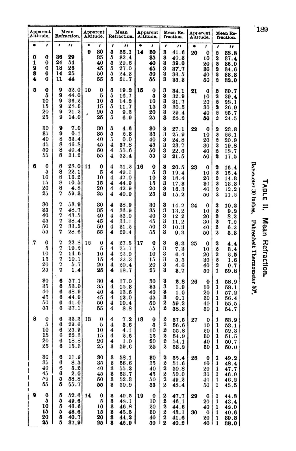
207 *
208 190 c g o 1 t5 LJ ffl
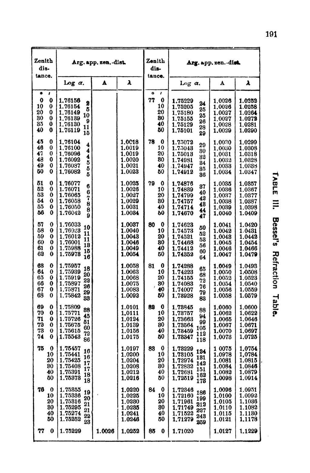
209 191
210 192
211
212 194 I.2 -a at E J 1 $. M-J a* CO H

213 196 r< " j? 8 P CL P

214 190 TJ rf g I < I w ctf bb > UJ

215 197 5 II F
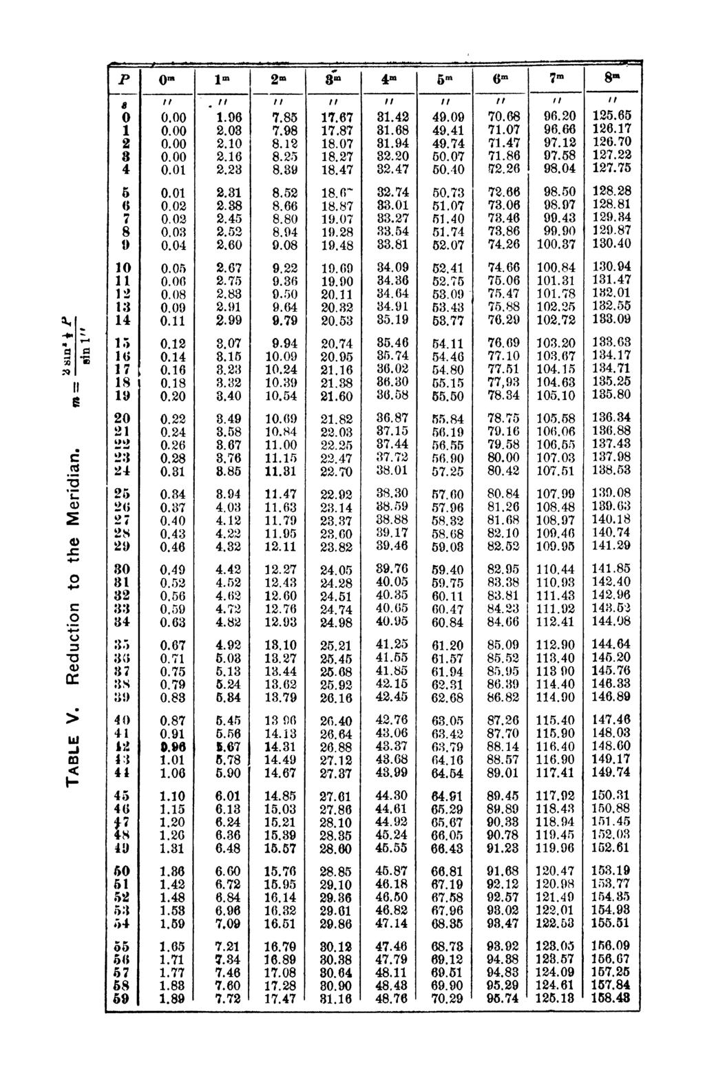
216

217 m < ID CD Q- IT CD CD -j 51"
 CC")
218 200 c o I T5 4) CC CO

219 a* 201 CO r m 33 (D a c o o' 3 IT CD n> -i 3
CHAPTER 20 SIGHT REDUCTION
 CHAPTER 20 SIGHT REDUCTION BASIC PRINCIPLES 2000. Introduction Reducing a celestial sight to obtain a line of position consists of six steps: 1. Correcting sextant altitude (hs) to obtain observed altitude
is a revolution relative to a fixed celestial position. is the instant of transit of mean equinox relative to a fixed meridian position.
 PERIODICITY FORMULAS: Sidereal Orbit Tropical Year Eclipse Year Anomalistic Year Sidereal Lunar Orbit Lunar Mean Daily Sidereal Motion Lunar Synodical Period Centenial General Precession Longitude (365.25636042
LOCATING CELESTIAL OBJECTS: COORDINATES AND TIME. a. understand the basic concepts needed for any astronomical coordinate system.
 UNIT 2 UNIT 2 LOCATING CELESTIAL OBJECTS: COORDINATES AND TIME Goals After mastery of this unit, you should: a. understand the basic concepts needed for any astronomical coordinate system. b. understand
The Position of the Sun. Berthold K. P. Horn. necessary to know the position of the sun in the sky. This is particularly
 MASSACHUSETTS INSTITUTE OF TECHNOLOGY ARTIFICIAL INTELLIGENCE LABORATORY Working Paper No. 162 March 1978 The Position of the Sun Berthold K. P. Horn Abstract. The appearance of a surface depends dramatically
Fundamentals of Satellite technology
 Fundamentals of Satellite technology Prepared by A.Kaviyarasu Assistant Professor Department of Aerospace Engineering Madras Institute Of Technology Chromepet, Chennai Orbital Plane All of the planets,
Chapter 1: Discovering the Night Sky. The sky is divided into 88 unequal areas that we call constellations.
 Chapter 1: Discovering the Night Sky Constellations: Recognizable patterns of the brighter stars that have been derived from ancient legends. Different cultures have associated the patterns with their
Name: Date: 5. The bright stars Vega, Deneb, and Altair form A) the summer triangle. B) the winter triangle. C) the Big Dipper. D) Orion, the Hunter.
 the summer triangle. B) the winter triangle. C) the Big Dipper. D) Orion, the Hunter.") Name: Date: 1. If there are about 6000 stars in the entire sky that can be seen by the unaided human eye, about how many stars would be seen at a particular instant on a given dark night from a single
Name: Date: 1. If there are about 6000 stars in the entire sky that can be seen by the unaided human eye, about how many stars would be seen at a particular instant on a given dark night from a single
Chapter 2. Altitude Measurement
 Chapter Altitude Measurement Although altitudes and zenith distances are equally suitable for navigational calculations, most formulas are traditionally based upon altitudes which are easily accessible
CELESTIAL COORDINATES
 ASTR 1030 Astronomy Lab 27 Celestial Coordinates CELESTIAL COORDINATES GEOGRAPHIC COORDINATES The Earth's geographic coordinate system is familiar to everyone - the north and south poles are defined by
Satellite Communications
 Satellite Communications Lecture (3) Chapter 2.1 1 Gravitational Force Newton s 2nd Law: r r F = m a Newton s Law Of Universal Gravitation (assuming point masses or spheres): Putting these together: r
PHYS 160 Astronomy Test #1 Fall 2017 Version B
 PHYS 160 Astronomy Test #1 Fall 2017 Version B 1 I. True/False (1 point each) Circle the T if the statement is true, or F if the statement is false on your answer sheet. 1. An object has the same weight,
Introduction To Modern Astronomy I: Solar System
 ASTR 111 003 Fall 2007 Lecture 02 Sep. 10, 2007 Introduction To Modern Astronomy I: Solar System Introducing Astronomy (chap. 1-6) Planets and Moons (chap. 7-15) Chap. 16: Our Sun Chap. 28: Search for
AFPAM MARCH Chapter 8 CELESTIAL CONCEPTS
 AFPAM11-216 1 MARCH 2001 197 Section 8A Introduction to Celestial Concepts Chapter 8 CELESTIAL CONCEPTS 8.1. Basics. Celestial navigation is a universal aid to dead reckoning (DR). Because it is available
The Celestial Sphere. GEK1506 Heavenly Mathematics: Cultural Astronomy
 The Celestial Sphere GEK1506 Heavenly Mathematics: Cultural Astronomy Helmer Aslaksen Department of Mathematics National University of Singapore aslaksen@math.nus.edu.sg www.math.nus.edu.sg/aslaksen/ The
NAVIGATION THEORY QUESTIONS Basics of Navigation
 NAVIGATION THEORY QUESTIONS Basics of Navigation Q610065 look at it The angle between the plane of the ecliptic and the plane of equator is approx? 23.5 degrees In which two months of the year is the difference
Altitude NAVIGATION. Visible Horizon
 Altitude Visible Horizon Rational Horizon Sensible Horizon Dip Polar Distance A small circle on the surface of the earth, containing the points of intersection between the observer s eye sight and the
Modern Navigation. Thomas Herring
 12.215 Modern Navigation Thomas Herring Review of Monday s Class Spherical Trigonometry Review plane trigonometry Concepts in Spherical Trigonometry Distance measures Azimuths and bearings Basic formulas:
Geometry of Earth Sun System
 12S56 Geometry of Earth Sun System Figure below shows the basic geometry Northern Hemisphere Winter ω equator Earth s Orbit Ecliptic ω ω SUN equator Northern Hemisphere Spring Northern Hemisphere Fall
UNIT 6 CELESTIAL SPHERE AND EQUINOCTIAL SYSTEM OF COORDINATES
 UNIT 6 CELESTIAL SPHERE AND EQUINOCTIAL SYSTEM OF COORDINATES Structure 6.1 Introduction Objectives 6.2 References 6.3 Apparent Annual Motion of the Sun and the Concept of the Ecliptic and the Obliquity
Celestial Sphere Spectroscopy (Something interesting; e.g., advanced data analyses with IDL)
") AST326, 2010 Winter Semester Celestial Sphere Spectroscopy (Something interesting; e.g., advanced data analyses with IDL) Practical Assignment: analyses of Keck spectroscopic data from the instructor (can
AST326, 2010 Winter Semester Celestial Sphere Spectroscopy (Something interesting; e.g., advanced data analyses with IDL) Practical Assignment: analyses of Keck spectroscopic data from the instructor (can
Knowing the Heavens. Goals: Constellations in the Sky
 Goals: Knowing the Heavens To see how the sky changes during a night and from night to night. To measure the positions of stars in celestial coordinates. To understand the cause of the seasons. Constellations
The celestial sphere, the coordinates system, seasons, phases of the moon and eclipses. Chapters 2 and S1
 The celestial sphere, the coordinates system, seasons, phases of the moon and eclipses Chapters 2 and S1 The celestial sphere and the coordinates system Chapter S1 How to find our way in the sky? Let s
Understanding Positional Astronomy Part 2 Celestial Co-ordinates Difficulty: Intermediate
 Exercise: Understanding Positional Astronomy Part 2 Celestial Co-ordinates Difficulty: Intermediate Objectives In Part 1 you learned about Celestial Sphere and how the stars appear to move across the night
Knowing the Heavens. Goals: Constellations in the Sky
 Goals: Knowing the Heavens To see how the sky changes during a night and from night to night. To measure the positions of stars in celestial coordinates. To understand the cause of the seasons. Constellations
4 Solar System and Time
 4 olar ystem and Time 4.1 The Universe 4.1.1 Introduction The Universe consists of countless galaxies distributed throughout space. The bodies used in astro navigation belong to the Galaxy known as the
INTRODUCTION FOREWORD
 FOREWORD The Sight Reduction Tables for Air Navigation consist of three volumes of comprehensive tables of altitude and azimuth designed for the rapid reduction of astronomical sights in the air. This
3) During retrograde motion a planet appears to be A) dimmer than usual. B) the same brightness as usual C) brighter than usual.
 During retrograde motion a planet appears to be A) dimmer than usual. B) the same brightness as usual C) brighter than usual.") Descriptive Astronomy (ASTR 108) Exam 1 B February 17, 2010 Name: In each of the following multiple choice questions, select the best possible answer. In the line on the scan sheet corresponding to the
Descriptive Astronomy (ASTR 108) Exam 1 B February 17, 2010 Name: In each of the following multiple choice questions, select the best possible answer. In the line on the scan sheet corresponding to the
1) Kepler's third law allows us to find the average distance to a planet from observing its period of rotation on its axis.
 Kepler's third law allows us to find the average distance to a planet from observing its period of rotation on its axis.") Descriptive Astronomy (ASTR 108) Exam 1 A February 17, 2010 Name: In each of the following multiple choice questions, select the best possible answer. In the line on the scan sheet corresponding to the
Descriptive Astronomy (ASTR 108) Exam 1 A February 17, 2010 Name: In each of the following multiple choice questions, select the best possible answer. In the line on the scan sheet corresponding to the
The sky and the celestial sphere
 Chapter 1 The sky and the celestial sphere The Sun, and sometimes the Moon are, by and large, the only astronomical objects visible in the day sky. Traditionally, astronomy has been a nocturnal activity.
ASTRONOMICAL COORDINATE SYSTEMS CELESTIAL SPHERE
 ASTRONOMICAL COORDINATE SYSTEMS CELESTIAL SPHERE To the naked eye, stars appear fixed on the sky with respect to one another. These patterns are often grouped into constellations. Angular measurements
CHAPTER 19 SIGHT REDUCTION
 CHAPTER 19 SIGHT REDUCTION BASIC PROCEDURES 1900. Computer Sight Reduction The purely mathematical process of sight reduction is an ideal candidate for computerization, and a number of different hand-held
Oberth: Energy vs. Momentum
 1 2 The Oberth Effect 3 Oberth: Energy vs. Momentum 4 The Celestial Sphere From our perspective on Earth the stars appear embedded on a distant 2-dimensional surface the Celestial Sphere. 5 The Celestial
Celestial Mechanics III. Time and reference frames Orbital elements Calculation of ephemerides Orbit determination
 Celestial Mechanics III Time and reference frames Orbital elements Calculation of ephemerides Orbit determination Orbital position versus time: The choice of units Gravitational constant: SI units ([m],[kg],[s])
Name and Student ID Section Day/Time:
 AY2 - Overview of the Universe - Midterm #1 - Instructor: Maria F. Duran Name and Student ID Section Day/Time: 1) Imagine we ve discovered a planet orbiting another star at 1 AU every 6 months. The planet
CHAPTER 2 INTERPOLATION
 CHAPTER 2 INTERPOLATION FINDING THE VALUE BETWEEN TABULATED ENTRIES 200. Introduction When one quantity varies with changing values of a second quantity, and the mathematical relationship of the two is
Astronomy 291. Professor Bradley M. Peterson
 Astronomy 291 Professor Bradley M. Peterson The Sky As a first step, we need to understand the appearance of the sky. Important points (to be explained): The relative positions of stars remain the same
Chapter S1 Celestial Timekeeping and Navigation. How do we define the day, month, year, and planetary time periods?
 Chapter S1 Celestial Timekeeping and Navigation S1.1 Astronomical Time Periods Our goals for learning:! How do we define the day, month, year, and planetary time periods?! How do we tell the time of day?!
t S 18. Determining Planetary Co-ordinates
 8. Determining Planetary Co-ordinates θ θ 0 ω R In the heliocentric reference frame which rotates with the Earth s orbital motion, suppose that initially a planet s unplanet line makes an angle θ 0 with
One sine wave is 7.64 minutes peak to peak variation. Two sine waves is 9.86
 WHY THE SUN IS SOMETIMES FAST AND SOMETIMES SLOW As the earth orbits the sun in an ellipse, it goes faster approaching the sun and slower when receding, just like when you throw a ball up in the air and
Earth Moon Motions A B1
 Earth Moon Motions A B1 1. The Coriolis effect provides evidence that Earth (1) rotates on its axis (2) revolves around the Sun (3) undergoes cyclic tidal changes (4) has a slightly eccentric orbit 9.
Lecture Module 2: Spherical Geometry, Various Axes Systems
 1 Lecture Module 2: Spherical Geometry, Various Axes Systems Satellites in space need inertial frame of reference for attitude determination. In a true sense, all bodies in universe are in motion and inertial
Observing the Universe for Yourself
 Observing the Universe for Yourself Figure 6-20 Solar-System Formation What does the universe look like from Earth? With the naked eye, we can see more than 2,000 stars as well as the Milky Way. A constellation
ANNEX 1. DEFINITION OF ORBITAL PARAMETERS AND IMPORTANT CONCEPTS OF CELESTIAL MECHANICS
 ANNEX 1. DEFINITION OF ORBITAL PARAMETERS AND IMPORTANT CONCEPTS OF CELESTIAL MECHANICS A1.1. Kepler s laws Johannes Kepler (1571-1630) discovered the laws of orbital motion, now called Kepler's laws.
Astronomy. The Seasons
 Astronomy The Seasons The seasons are caused by the inclination of the Earth s axis: when a hemisphere is tipped toward the Sun, the Sun is more directly above it. At the Summer Solstice the tilt is most
Chapter S1 Lecture. The Cosmic Perspective Seventh Edition. Celestial Timekeeping and Navigation Pearson Education, Inc.
 Chapter S1 Lecture The Cosmic Perspective Seventh Edition Celestial Timekeeping and Navigation 2014 Pearson Education, Inc. Celestial Timekeeping and Navigation 2014 Pearson Education, Inc. S1.1 Astronomical
These notes may contain copyrighted material! They are for your own use only during this course.
 Licensed for Personal Use Only DO NOT DISTRIBUTE These notes may contain copyrighted material! They are for your own use only during this course. Distributing them in anyway will be considered a breach
Exam #1 Covers material from first day of class, all the way through Tides and Nature of Light Supporting reading chapters 1-5 Some questions are
 Exam #1 Covers material from first day of class, all the way through Tides and Nature of Light Supporting reading chapters 1-5 Some questions are concept questions, some involve working with equations,
The Earth is a Rotating Sphere
 The Earth is a Rotating Sphere The Shape of the Earth Earth s Rotation ( and relative movement of the Sun and Moon) The Geographic Grid Map Projections Global Time The Earth s Revolution around the Sun
Chapter 2 Lecture. The Cosmic Perspective Seventh Edition. Discovering the Universe for Yourself
 Chapter 2 Lecture The Cosmic Perspective Seventh Edition Discovering the Universe for Yourself Discovering the Universe for Yourself 2.1 Patterns in the Night Sky Our goals for learning: What does the
The following terms are some of the vocabulary that students should be familiar with in order to fully master this lesson.
 Lesson 211: EARTH'S SEASONS Students learn the complex geometry and planetary motions that cause Earth to have four distinct seasons. Fundamental Questions Attempting to give thorough and reasonable answers
Earth-Centered, Earth-Fixed Coordinate System
 Fundamentals of Global Positioning System Receivers: A Software Approach James Bao-Yen Tsui Copyright 2000 John Wiley & Sons, Inc. Print ISBN 0-471-38154-3 Electronic ISBN 0-471-20054-9 CHAPTER FOUR Earth-Centered,
PHSC 1053: Astronomy Time and Coordinates
 PHSC 1053: Astronomy Time and Coordinates Astronomical Clocks Earth s Rotation on its Axis Time between two successive meridian transits of the sun 1 solar day (our adopted clock time) 24 hours (86,400
a. 0.5 AU b. 5 AU c. 50 AU d.* AU e AU
 1 AST104 Sp04: WELCOME TO EXAM 1 Multiple Choice Questions: Mark the best answer choice. Read all answer choices before making selection. (No credit given when multiple answers are marked.) 1. A galaxy
Coordinate Systems for Astronomy or: How to get your telescope to observe the right object
 Coordinate Systems for Astronomy or: How to get your telescope to observe the right object Figure 1: Basic definitions for the Earth Definitions - Poles, Equator, Meridians, Parallels The rotation of the
Topic Guide: The Celestial Sphere. GCSE (9-1) Astronomy. Pearson Edexcel Level 1/Level 2 GCSE (9-1) in Astronomy (1AS0)
 Astronomy. Pearson Edexcel Level 1/Level 2 GCSE (9-1) in Astronomy (1AS0)") Topic Guide: The Celestial Sphere GCSE (9-1) Astronomy Pearson Edexcel Level 1/Level 2 GCSE (9-1) in Astronomy (1AS0) The Celestial Sphere Contents Specification Points 1 The Astronomy 2 Equatorial coordinates
Topic Guide: The Celestial Sphere GCSE (9-1) Astronomy Pearson Edexcel Level 1/Level 2 GCSE (9-1) in Astronomy (1AS0) The Celestial Sphere Contents Specification Points 1 The Astronomy 2 Equatorial coordinates
Astronomy Section 2 Solar System Test
 is really cool! 1. The diagram below shows one model of a portion of the universe. Astronomy Section 2 Solar System Test 4. Which arrangement of the Sun, the Moon, and Earth results in the highest high
2. Modern: A constellation is a region in the sky. Every object in the sky, whether we can see it or not, is part of a constellation.
 6/14 10. Star Cluster size about 10 14 to 10 17 m importance: where stars are born composed of stars. 11. Galaxy size about 10 21 m importance: provide a stable environment for stars. Composed of stars.
Observing the Night Sky: Locating Objects
 Observing the Night Sky: Locating Objects As I left the house this morning, there was a bright bluish light above and to the left of my neighbors house (approximately East) and a big very bright object
Brock University. Test 1, May 2014 Number of pages: 9 Course: ASTR 1P01 Number of Students: 500 Date of Examination: May 21, 2014
 Brock University Test 1, May 2014 Number of pages: 9 Course: ASTR 1P01 Number of Students: 500 Date of Examination: May 21, 2014 Number of hours: 50 min Time of Examination: 14:00 14:50 Instructor: B.Mitrović
Discovering the Night Sky
 Discovering the Night Sky Guiding Questions 1. What role did astronomy play in ancient civilizations? 2. Are the stars that make up a constellation actually close to one another? 3. Are the same stars
Discovering the Night Sky
 Guiding Questions Discovering the Night Sky 1. What role did astronomy play in ancient civilizations? 2. Are the stars that make up a constellation actually close to one another? 3. Are the same stars
astronomy A planet was viewed from Earth for several hours. The diagrams below represent the appearance of the planet at four different times.
 astronomy 2008 1. A planet was viewed from Earth for several hours. The diagrams below represent the appearance of the planet at four different times. 5. If the distance between the Earth and the Sun were
A User s Guide to the Sky
 A User s Guide to the Sky Constellations Betelgeuse Rigel Stars are named by a Greek letter ( ) according to their relative brightness within a given constellation plus the possessive form of the name
Knowing the Heavens. Chapter Two. Guiding Questions. Naked-eye (unaided-eye) astronomy had an important place in ancient civilizations
 astronomy had an important place in ancient civilizations") Knowing the Heavens Chapter Two Guiding Questions 1. What role did astronomy play in ancient civilizations? 2. Are the stars that make up a constellation actually close to one another? 3. Are the same
Knowing the Heavens Chapter Two Guiding Questions 1. What role did astronomy play in ancient civilizations? 2. Are the stars that make up a constellation actually close to one another? 3. Are the same
Brock University. Test 1, October 2017 Number of pages: 9 Course: ASTR 1P01, Section 1 Number of Students: 470 Date of Examination: October 3, 2017
 Brock University Test 1, October 2017 Number of pages: 9 Course: ASTR 1P01, Section 1 Number of Students: 470 Date of Examination: October 3, 2017 Number of hours: 50 min Time of Examination: 17:00 17:50
RECOMMENDATION ITU-R S Impact of interference from the Sun into a geostationary-satellite orbit fixed-satellite service link
 Rec. ITU-R S.1525-1 1 RECOMMENDATION ITU-R S.1525-1 Impact of interference from the Sun into a geostationary-satellite orbit fixed-satellite service link (Question ITU-R 236/4) (21-22) The ITU Radiocommunication
Meridian Circle through Zenith, North Celestial Pole, Zenith Direction Straight Up from Observer. South Celestial Pole
 Chapter 3 How Earth and Sky Work- Effects of Latitude In chapters 3 and 4we will learn why our view of the heavens depends on our position on the Earth, the time of day, and the day of the year. We will
The Measurement of Time
 CHAPTER TWO The Measurement of Time Solar Time In antiquity the time of day was measured by the direction of a shadow cast in sunlight. This resulted in the development of a wide variety of sophisticated
CHENDU COLLEGE OF ENGINEERING & TECHNOLOGY DEPARTMENT OF CIVIL ENGINEERING SUB CODE & SUB NAME : CE6404 SURVEYING II
 CHENDU COLLEGE OF ENGINEERING & TECHNOLOGY DEPARTMENT OF CIVIL ENGINEERING SUB CODE & SUB NAME : CE6404 SURVEYING II UNIT I CONTROL SURVEYING PART A (2 MARKS) 1. What is the main principle involved in
Earth Science, 13e Tarbuck & Lutgens
 Earth Science, 13e Tarbuck & Lutgens Origins of Modern Astronomy Earth Science, 13e Chapter 21 Stanley C. Hatfield Southwestern Illinois College Early history of astronomy Ancient Greeks Used philosophical
Earth Science, 11e. Origin of Modern Astronomy Chapter 21. Early history of astronomy. Early history of astronomy. Early history of astronomy
 2006 Pearson Prentice Hall Lecture Outlines PowerPoint Chapter 21 Earth Science 11e Tarbuck/Lutgens This work is protected by United States copyright laws and is provided solely for the use of instructors
Exercise 1.0 THE CELESTIAL EQUATORIAL COORDINATE SYSTEM
 Exercise 1.0 THE CELESTIAL EQUATORIAL COORDINATE SYSTEM Equipment needed: A celestial globe showing positions of bright stars and Messier Objects. I. Introduction There are several different ways of representing
MAE 180A: Spacecraft Guidance I, Summer 2009 Homework 2 Due Tuesday, July 14, in class.
 MAE 180A: Spacecraft Guidance I, Summer 2009 Homework 2 Due Tuesday, July 14, in class. Guidelines: Please turn in a neat and clean homework that gives all the formulae that you have used as well as details
Chapter 2 Discovering the Universe for Yourself. Copyright 2012 Pearson Education, Inc.
 Chapter 2 Discovering the Universe for Yourself 1 2.1 Patterns in the Night Sky Our goals for learning: What does the universe look like from Earth? Why do stars rise and set? Why do the constellations
Astronomical coordinate systems. ASTR320 Monday January 22, 2018
 Astronomical coordinate systems ASTR320 Monday January 22, 2018 Special public talk this week: Mike Brown, Pluto Killer Wednesday at 7:30pm in MPHY204 Other news Munnerlyn lab is hiring student engineers
Coordinate Systems. Basis for any 3D Coordinate System. 2. Locate the x-y plane (the fundamental plane ) Usual approach to define angles:
 Usual approach to define angles:") Coordinate Systems Basis for any 3D Coordinate System Basic steps for the definition of a 3D coordinate system:. Locate the origin. Locate the -y plane (the fundamental plane ) 3. Decide on direction of
Coordinate Systems Basis for any 3D Coordinate System Basic steps for the definition of a 3D coordinate system:. Locate the origin. Locate the -y plane (the fundamental plane ) 3. Decide on direction of
CHAPTER 24 THE SAILINGS
 CHAPTER 24 THE SAILINGS INTRODUCTION 2400. Introduction Dead reckoning involves the determination of one s present or future position by projecting the ship s course and distance run from a known position.
PHYS 160 Astronomy Test #1 Name Answer Key Test Version A
 PHYS 160 Astronomy Test #1 Name Answer Key Test Version A True False Multiple Choice 1. T 1. C 2. F 2. B 3. T 3. A 4. T 4. E 5. T 5. B 6. F 6. A 7. F 7. A 8. T 8. D 9. F 9. D 10. F 10. B 11. B 12. D Definitions
Coordinates on the Sphere
 Survey Observations Coordinates on the Sphere Any position on the surface of a sphere (such as the Earth or the night sky) can be expressed in terms of the angular coordinates latitude and longitude Latitude
The point in an orbit around the Sun at which an object is at its greatest distance from the Sun (Opposite of perihelion).
.") ASTRONOMY TERMS Albedo Aphelion Apogee A measure of the reflectivity of an object and is expressed as the ratio of the amount of light reflected by an object to that of the amount of light incident upon
ASTRONOMY TERMS Albedo Aphelion Apogee A measure of the reflectivity of an object and is expressed as the ratio of the amount of light reflected by an object to that of the amount of light incident upon
Aileen A. O Donoghue Priest Associate Professor of Physics
 SOAR: The Sky in Motion Life on the Tilted Teacup Ride Celestial Coordinates and the Day Aileen A. O Donoghue Priest Associate Professor of Physics Reference Points Poles Equator Prime Meridian Greenwich,
2. Descriptive Astronomy ( Astronomy Without a Telescope )
") How do we locate stars in the heavens? 2. Descriptive Astronomy ( Astronomy Without a Telescope ) What stars are visible from a given location? Where is the sun in the sky at any given time? Where are
How do we locate stars in the heavens? 2. Descriptive Astronomy ( Astronomy Without a Telescope ) What stars are visible from a given location? Where is the sun in the sky at any given time? Where are
Chapter 2 Lecture. The Cosmic Perspective Seventh Edition. Discovering the Universe for Yourself Pearson Education, Inc.
 Chapter 2 Lecture The Cosmic Perspective Seventh Edition Discovering the Universe for Yourself Discovering the Universe for Yourself 2.1 Patterns in the Night Sky Our goals for learning: What does the
In all cases assume the observer is located at the latitude of Charlottesville (38 degrees north).
.") 1. Recalling that azimuth is measured around the sky from North (North is 0 degrees, East is 90 degrees, South is 180 degrees, and West is 270 degrees) estimate (do not calculate precisely) the azimuth
1. Recalling that azimuth is measured around the sky from North (North is 0 degrees, East is 90 degrees, South is 180 degrees, and West is 270 degrees) estimate (do not calculate precisely) the azimuth
2. Knowing the Heavens
 2. Knowing the Heavens Ancient naked-eye astronomy Eighty-eight constellations The sky s ever-changing appearance The celestial sphere Celestial coordinates Seasons: Earth s axial tilt Precession of Earth
Cartesian Coordinates Need two dimensional system 2 number lines perpendicular to each other X-axis is horizontal Y-axis is vertical Position relative
 General Physical Science Chapter 15 Place and Time Space and Time Einstein Space and time related Single entity Time is the 4 th dimension! Cartesian Coordinates Need some system to tell us where something
CHAPTER 8 PLANETARY MOTIONS
 1 CHAPTER 8 PLANETARY MOTIONS 8.1 Introduction The word planet means wanderer (πλάνητες αστέρες wandering stars); in contrast to the fixed stars, the planets wander around on the celestial sphere, sometimes
Lab 2. Observing the Sky. 2.1 Overview
 Lab 2 Observing the Sky 2.1 Overview This project is focused on naked eye observations of the sky understanding the monthly lunar orbit, visualizing the positions of the Moon, Earth, and Sun throughout
Physics Lab #4:! Starry Night Student Exercises I!
 Physics 10293 Lab #4: Starry Night Student Exercises I Introduction For today s lab, we are going to let the Starry Night software do much of the work for us. We re going to walk through some of the sample
3. The Sun s Position
 3. The Sun s Position In order to understand how to collect energy from the sun, one must first be able to predict the location of the sun relative to the collection device. In this chapter we develop
Chapter 0 2/19/2014. Lecture Outline. 0.1 The Obvious View. Charting the Heavens. 0.1 The Obvious View. 0.1 The Obvious View. Units of Chapter 0
 Lecture Outline Chapter 0 Charting the Heavens Earth is average we don t occupy any special place in the universe Universe: Totality of all space, time, matter, and energy Astronomy: Study of the universe
ASTRONOMICAL NAVIGATION
 Basic terms ASTRONOMICAL NAVIGATION *astronomical navigation *compilation *astronomical tabels *celestial observations *solution of a sight * Sun/Moon/star sight *spherical trigonometry *PZX triangle *celestial
6/17. Universe from Smallest to Largest:
 6/17 Universe from Smallest to Largest: 1. Quarks and Leptons fundamental building blocks of the universe size about 0 (?) importance: quarks combine together to form neutrons and protons. One of the leptons
Astr 1050 Mon. Jan. 31, 2017
 Astr 1050 Mon. Jan. 31, 2017 Finish Ch. 2: Eclipses & Planetary Motion Seasons Angular Size formula Eclipses Planetary Motion Reading: For Today: Finish Chapter 2 For Monday: Start Chapter 3 Homework on
Chapter 2 Discovering the Universe for Yourself
 Chapter 2 Discovering the Universe for Yourself 2.1 Patterns in the Night Sky Our goals for learning: What does the universe look like from Earth? Why do stars rise and set? Why do the constellations we
Astrology Class Madison, Wisconsin. 43 North 89 West. September Daylight
 Astrology Class Madison, Wisconsin 43 North 89 West 7 32 September 21 2005 Daylight Astrology Class Madison, Wisconsin September 21,2005 7:32 43 North 89 West Names & Planetary Character Luminaries Symbols
The time they chose was the Vernal Equinox of March 20, 2000, at 7:30 AM Greenwich Mean Time (GMT). Right Ascension Offset
. Right Ascension Offset") Star Coordinates and the Celestial Dome Astronomers have mapped out the sky in the shape of a spherical dome the Celestial Sphere, where earth is just a tiny spec at the center of the dome. The celestial
Star Coordinates and the Celestial Dome Astronomers have mapped out the sky in the shape of a spherical dome the Celestial Sphere, where earth is just a tiny spec at the center of the dome. The celestial
AST 2010 Descriptive Astronomy Study Guide Exam I
 AST 2010 Descriptive Astronomy Study Guide Exam I Wayne State University 1 Introduction and overview Identify the most significant structures in the universe: Earth, planets, Sun, solar system, stars,
Celestial Navigation
 A Short Guide to Celestial Navigation Copyright 1997-011 Henning Umland Permission is granted to copy, distribute and/or modify this document under the terms of the GNU Free Documentation License, Version
Time and Diurnal Motion. 1a. The Earth Is Flat. 1c. Aristotle ( BC) 1b. The Earth Is Round. Time and Diurnal Motion
 1b. The Earth Is Round. Time and Diurnal Motion") Time and Diurnal Motion Time and Diurnal Motion A. Geography: mapping the earth 2 B. Equatorial Coordinates C. Local Horizon System A. Geography: mapping the earth Geometry: measure the earth! 1) The earth
Time and Diurnal Motion Time and Diurnal Motion A. Geography: mapping the earth 2 B. Equatorial Coordinates C. Local Horizon System A. Geography: mapping the earth Geometry: measure the earth! 1) The earth