MODELING AND MODIFICATION FOR DISTRIBUTION TRANSFORMER (250 KVA, 11/0.416 KV) TO REDUCE THE TOTAL LOSSES
|
|
|
- Conrad Snow
- 5 years ago
- Views:
Transcription
1 MODELING AND MODIFICATION FOR DISTRIBUTION TRANSFORMER (250 KVA, 11/0.416 KV) TO REDUCE THE TOTAL LOSSES Assist. Prof. Ibtisam A. Hasan Dr. Sahar R. Fafraj Eng. Azhar K. Azeez Electromechanical Eng. Dept. Electromechanical Eng. Dept. Dept. Electromechanical Eng. University Of Technolog University Of Technology University Of Technology Received on 21 April 2016 Accepted on 25 August 2016 ABSTRACT This paper presents the electromagnetic model for the 3- phase distribution transformer 250 KVA 11/.416KV core type. This model based upon using "ANSYS PROGRAM" to obtain the flux density distribution and losses, in this work, it has been change core material from silicon steel (Si.St.) to amorphous steel (Am. St.). Where, the iron losses reduction with 90%. The result for computer program are compared with practical measurements. Key word Distribution transformer, Flux density distribution, Transformer losses, amorphous steel, ANSYS. (250 KVA, 11/0.416KV) Nomenclature 50 11/.416, 250KVA " ANSYS"....%90 E 1 1m Maximum magnetic flux density R.M.S value for Primary Electro motive force R.M.S value for Secondary Electro motive force Electro motive force per turn Electro motive force Mean primary Electro motive force frequency Primary current Secondary current Primary turn number 479
2 (.) Secondary turn number Power losses of primary winding Magnetic flux Power losses of secondary winding Total power losses of windings Specific power losses Total power losses of core Total power losses of transformer Primary winding resistance Secondary winding resistance Transformer capacity Primary phase voltage Secondary phase voltage Weight of leg Weight of yoke Efficiency 1. INTRODUCTION A transformer is a highly efficient static machine operating on the principle of mutual induction. In alternating current power circuit the transformer converts it's from one voltage level to another through inductively coupled conductors and is available in a variety of power ratings. Distribution transformer represents important part a power system. One of the major and important parameters dominant a distribution transformer's age is hot spot temperature. However, the heat dissipation is problem in distribution transformers. The losses in the distribution transformer convert to heat but by accumulated this heat without being dissipated the life of the transformer (Haritha2011). Because of this it must be reduce the losses in distribution transformer to increase the efficiency of it's and then the life of the distribution transformer become longest. The distribution transformer is complicity so the finite element method has been used to study the electromagnetic; Finite element modeling (FEM) of electromagnetic fields, which is very advanced technique available as commercial software to provide a reliable tool for the design and performance prediction of electromechanical devices. In this work, the general-purpose finite element package "ANSYS15" is used. ANSYS software is a powerful universal software based on the finite element algorithmic; the design and analysis the distribution transformer required its. The transformer is modelling before manufacturing and within the process of design (Thamir et al 2014). (Dorinel et al 2013); study validate a designed three phase power transformer with modern software that use finite element method (ANSYS Maxwell 3D and ANSYS Mechanical). It found the magnitude of B field, the regions with problems and the value of the total core losses for the same transformer but at 3 types of voltages 330 kv, 400 kv and 430 kv. (Diako et al); used the finite element method to solve Maxwell and thermal (energy) equations to obtain the distribution temperature in the 3-phase (10 MVA, 63/20kV) transformer to find the flux density and hot spot temperature. (Kassim 2015); they used the finite element method (ANSYS, APDL) to analyze the 3 phase distribution transformer wound type to find the magnetic flux density distribution and force. (Man 2012); he used amorphous steel to reduce the losses for transformer. Where, it found the amourphous material reduced the iron loses by 90%. 480
3 (Neha et al 2015); they used new material to reduce the losses and improve the life time for transformer. Where, they found the amourphous material reduced the iron loses by 68% for 100 KVA. (Ravi et al 2013); this paper covers design of transformer using a new technology superior magnetic material with thin sheets of lazer grade or amorphous core. This design of transformer was carried out to find the better quality core to reduce the losses and improve the efficiency. (Riath 2009); presents an algorithm to design a complete three-phase distribution transformer. Where, this program gives several alternative designs for each required transformer and applied to standard distribution transformers used in the Iraqi power system. (Thamir et al 2014); they used the finite element method (ANSYS, APDL) to analyze the 3 phase distribution transformer (250 KVA, 11/0.416 KV, core type) to find the magnetic flux density distribution. 2. MATHEMETICAL MODEL OF DISTRIBUTION TRANSFORMER For initiating the design of the magnetic circuit (main dimensions of core) When applied the alternating voltage across the primary windings in transformer, flux ( ) and magnetizing current (I m ) is produced in the core. The flux is distributed uniformly over the core of transformer section and all primary and secondary turns of windings. The generated main flux is in alternative form, hence in the primary turns of windings, the electro motive force (e.m.f) induced due to the main flux changes as a follow (Mittle 2009), Assuming sinusoidal time variation of the flux, let = m cos wt, where is m the time-maximum value of the mutual flux in Weber, w=2 f, and f is the frequency of flux pulsation. Then ( )( m cos wt) = T 1 w m sin wt (2) The instantaneous value, the maximum is 1m = T 1 w m and the R.M.S. value E 1 = w N 1 m = ( 2) f N 1 m = 4.44f N 1 m (3) In each turn, the e.m.f. is E t = 4.44 f m (4) Whether the turn is part of the primary, secondary, or other winding, provided only that it links the flux m (Ravi et al 2013). Similarly, induced e.m.f. in secondary winding, E 2 = 4.44 f N 2 m (5) Obviously the primary and secondary e.m.f. the same ratio (1) = (6) 481
4 The iron losses produced from the eddy current and the hysteresis losses.it is can be calculated by weight of core = (.) ( + ) (7) Where, (.), is a specific iron loss for the core W/Kg taken from the curve of specific iron losses versus flux density. The copper losses produced from the load can be calculated by = + (9) The efficiency of transformer is = (10) (8) 3. TRANSFORMER MODEL USING FINITE ELEMENT METHOD The details of building FEM of the distribution transformer under study are presented to analyze of the distribution magnetic flux in the transformer. It has been used ANSYS Package Version 11 to model the distribution transformer. Table (1) shows the data of distribution transformer. 3.1 Transformer Geometry (Building and meshing) The transformer study is 250 kva, three phase distribution core type "stacked core" transformer. To build this solid model, it has been measured the dimensions of this transformer accurately. These dimensions of transformer were taken from the design documents from the manufacturing company (AlWAZIRIYA Company of Electrical Industries). Building of this solid model started by the key points, following step connect these key points by lines, and then create areas from these lines. ANSYS package includes several elements that can be used to model electromagnetic phenomena. In this work for low frequency electromagnetic analysis, 2-D Solid Element PLANE53 for iron core, coils and oil. The objective in building a solid model is to mesh that model with nodes and elements. Where, it must be specify the size and type of mesh before generating the mesh. It has been found (45560) nodes and (23634) elements as the best formatted mesh. 3.2 Applying Loads and Solution The coils of each phase (primary and secondary) is coupled degree of freedom, all nodes of secondary is coupled together in CURR and EMF but the nodes of primary is coupled together in CURR degree of freedom. Then the voltage is excited directly to primary coil for each phase, but the secondary coil is coupled with external load circuit. Flux parallel is applied as boundary condition to the outer line of core. The analysis of the electromagnetic model by ANSYS package must be specified. The analysis types of solution are static, harmonic and transient. In this work, harmonic analysis is used (ANSYS. 15 theory guid, 2015). The formulations of finite element analyzing for this model are based on 482
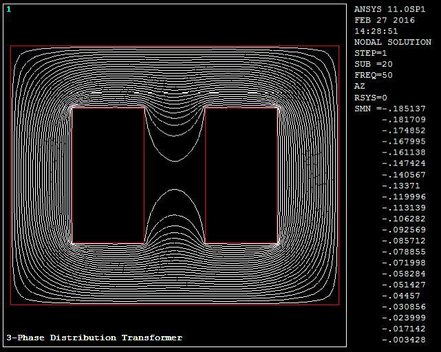
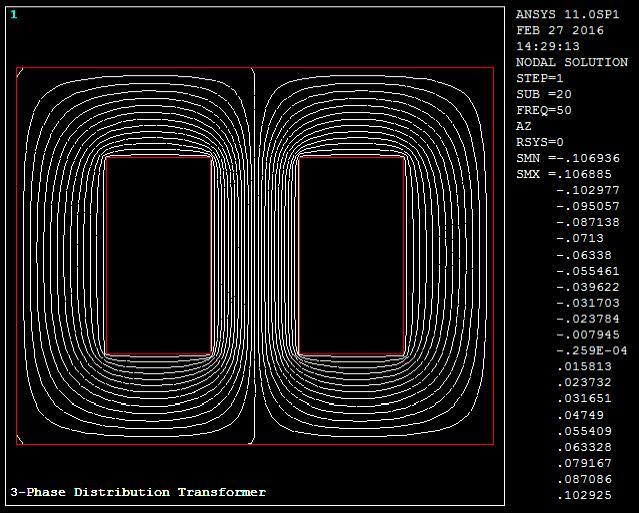
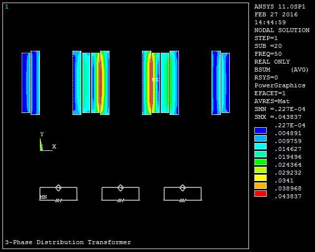
5 Maxwell s equations (magnetic vector potential formulations). This solution requires sub-step calculation which is used for the numerical solution in finite element model. The solution gives the unknown quantities which are represented as a degree of freedom Harmonic Analysis Two conditions are used for solving the model. The first condition at no-load to check if the model is true or not. Second condition at load, the model is resolved by applying a load on the secondary windings as explained below. a- No-Load Condition In this condition, the secondary winding is opened and applied voltage by direct excitation on the primary coils. The objective of this condition is to obtain the magnetizing current and to be sure the model is ready to the analysis. See figure (1) b- Full Load Condition In this case, the resistance is connected to the secondary coils. Where the load circuit is build and adjusted the load resistance to reach the primary coils rated current. Then, it has been calculate the losses and compared with practical measurement. See figure (2). Figure (3) shows the block chart for ANSYS steps. 4. RESULT AND DISCUSSION ANSYS program was used to show the performance and to calculate the losses for the transformer. In the following results and figures for two cases (conventional and amorphous core) the electrical behavior are discussed Please note that the belonging arrangement of the figures is for conventional core and amorphous core respectively Figures (4) and (5) show the flux line distribution of magnetic density of the model at no load condition for two cases. Figures (6) and (7) show the flux line distribution of magnetic density of the model at full load condition. These figures show that the flux line distributions are same when the transformer operates at two conditions (no-load and full load). This result was confirmed that the model gets good result. Figures (8) and (9) show the nodal plot of the flux density distribution for transformer. In general, the flux in the amorphous core less than in the conventional core because the saturation flux density for the amorphous less than the conventional core. Figures (10) and (11) show the vector plot for flux density distribution for transformer. Figures (12) and (13) show the nodal plot of magnetic flux density in High and low voltage coils. These figures show, the flux in Y-direction (height of coil) decreased gradually from the middle point of the coil height toward its endings. But, in X-direction the flux linearly increasing from outer side to inner side of low voltage coil and decreased linearly from inner side to outer side of high voltage coil. The reason of this distribution is that the flux increase with current and number of turns. The maximum value for flux density in real component was noticed in the phase (b) because the phase angle of it (0 0 ) but it has minimum value in the imaginary component. Figures (14) and (15) show the direction of leakage flux by vector plot. The flux in the primary winding has opposite direction of the secondary winding, because the current was flowing in the opposite directions inside the primary and secondary windings. The maximum value of flux density is at the phase (b) for real 483
6 component because the phase (b) has an angle equal to (0 0 ). And the imaginary component has the minimum value. Figures (16) and (17) show the heat joule in primary and secondary windings. In FEM heat joule value has been obtained by integrated the values of losses at all nodes, which forming each part of the transformer and then converted to heat. The amorphous core has lower heat joule than for the conventional core. 5. THE LOSSES RESULT The no load and load (iron and copper) losses have been calculated, using the ANSYS and MATLAB packages and then compared with experimental results to determine error percentage. Therefore, the efficient performance of the proposed model is checked. The type of core material plays a fundamental role in determining the amount of the losses generated. The core material has been replaced with amorphous; this caused to reduce the core losses about 90% from the losses for conventional core this percentage is match with ref. (Man 2016). The initial cost of the conventional core is approximate but the amorphous core is (Ravi et al 2013). This reduction depends on the amount of flux density saturation. In this material (amorphous), the saturation flux density is less than conventional core (silicon steel). Therefore, the specified core losses are reduced and subsequently the amount of heat generation, and caused decreasing the temperature rise inside the transformer and then enhance the efficiency of transformer. Table (2) shows the transformer losses. 6. CONCLUSION The distribution transformer (250 KVA, 11/.416V, core type, oil immersed), the results indicated that total losses for no load and load conditions be 0.59 and 2.99 Kw respectively by ANSYS but the when change the core material to Am.St. (Amorphous steel) the no load and load losses reduced by 90% and 5% respectively. REFERENCES (Dorinel C., Petre-Marian N. and Cristiana-Maria N ), "3D Finite Element Analysis of a Three Phase Power Transformer", EuroCon., Zagreb, Croatia, pp (Diaco Azizi, Ahmad, Gholami, Diar Azizi), "Hot Spot Temperature Analysis in 3 Phase Transformers Using FEM Method", International Journal of Modern Engineering Research, Vol. 1. (Kassim R. H. 2015), " ZIG-ZAG GROUNDING TRANSFORMER MODELING FOR ZERO- SEQUNCE IMPEDANCE CALCULATION USING FINITE ELEMENT METHOD, Diyala Journal of Engineering Sciences, Vol. 08, No. 06, pp (Man M. 2016), ""Distribution Transformer with Multi-Stepped Amorphous-Core"," Journal of Emerging Trends in Engineering and Applied Sciences, Pp (Mittle D. 2009), "Design of electrical machine", published by Standard Publishers Distributors, Delhi. (Neha S. and Sameena E. M.,2015) ""Evaluation of Energy Efficient Core Material of Distribution Transformer"," International Journal of Electrical and Electronics Research, vol.3, no. 1, pp
7 (Ravi K. V., Shalini V. and S.K. Bajpai 2013 ) "Efficiency Improvements in Transformers by Adoption of New Magnetic Material", International Journal of Emerging Technology and Advanced Engineering, Pp , Volume 3, Issue 3, March (Riath t. t ), "An algorithm for optimum design of three phase core type distribution transformer"," University of Babylon Journal, Vol.17, pp (Thamir A. and Methaaq T. J. 2014), "Design and Simulation of 11/0.4 kv Distribution Transformer Using ANSYS"," Eng. & Tech. Journal, Iraq, Vol.32,Part (A), No.2. ANSYS. 15 theory guid, Table (1) data of 250 KVA, Distribution Transformer, and Oil immersed Transformer Data Symbol Value Unit Transformer rated power S 250 KVA Frequency f 50 Hz Primary winding voltage HV V volts Secondary winding voltage LV V volts Number of phases 3, (delta/star) Table (2) Transformer losses No Load Losses (KW) Load Losses (KW) Conventional core Theoretical ANSYS Experimental Amorphous core Theoretical ANSYS Conventional core with 135 o Theoretical ANSYS Figure (1) Distribution transformer with open circuit (no-load) 485
")


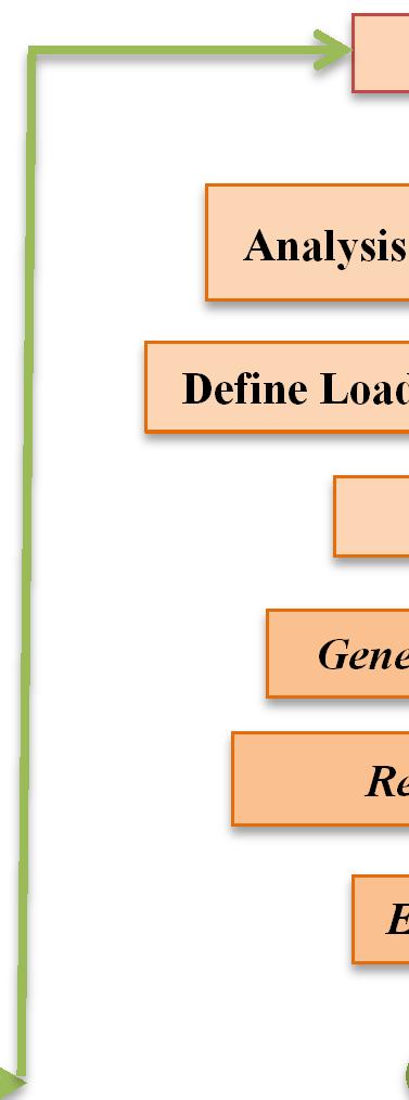
8 Figure (2) distribution transformer with external circuit load Start Preprocessor Element Type Real Constant Material Properties Modeling Solution Analysis Type (Harmonic) Define Load B.C. & Exited Voltage Solve General Postprocessor Results Plot & List Meshing Elec & Mag Cal Coupling End Figure (3) Block Diagram for ANSYS 486
 Flux line")
 2D flux line")
 Flux line")
 Flux")
 2D flux line distribution at")
9 . (a) Flux line distribution real component (b) Flux line distribution imaginary component Figure (4) 2D flux line distribution at no load of conventional core (a) Flux line distribution real component (b) Flux line distribution imaginary component Figure (5) 2D flux line distribution at no load of amorphous core (a) Flux line distribution real component (b) Flux line distribution imaginary component Figure (6) 2D flux line distribution at full load of conventional core 487
 Flux line")
 Flux line distribution")

 density of amorphous")
10 (a) Flux line distribution real component (b) Flux line distribution imaginary component Figure (7) Flux line distribution for amorphous core Figure (8) Nodal plot of magnetic flux density of conventional core Figure (9) Nodal plot of magnetic flux density of amorphous core 488


11 Figure (10) Vector plot of magnetic flux density of conventional core Figure (11) Vector plot of magnetic flux density of amorphous core Figure (12) Nodal plot of magnetic flux distribution of conventional core 489

 Vector plot of")


12 Figure (13) Nodal plot of magnetic flux distribution of amorphous core Figure (14) Vector plot of magnetic flux density of conventional core s Figure (15) Vector plot of magnetic flux density of amorphous core 490

")

13 Figure (16) Heat generation of conventional core Figure (17) Heat generation of amorphous core 491
Different Techniques for Calculating Apparent and Incremental Inductances using Finite Element Method
 Different Techniques for Calculating Apparent and Incremental Inductances using Finite Element Method Dr. Amer Mejbel Ali Electrical Engineering Department Al-Mustansiriyah University Baghdad, Iraq amerman67@yahoo.com
EN Power Electronics and Machines
 1/19 - Power Electronics and Machines Transformers Suryanarayana Doolla Department of Energy Science and Engineering Indian Institute of Technology, Bombay suryad@iitb.ac.in Lecture Organization - Modules
Eddy Current Losses in the Tank Wall of Power Transformers
 Eddy Current Losses in the Tank Wall of Power Transformers Erich Schmidt Institute of Electrical Drives and Machines, Vienna University of Technology A 14 Vienna, Austria, Gusshausstrasse 25 29 Phone:
ROEVER COLLEGE OF ENGINEERING & TECHNOLOGY ELAMBALUR, PERAMBALUR DEPARTMENT OF ELECTRICAL AND ELECTRONICS ENGINEERING ELECTRICAL MACHINES I
 ROEVER COLLEGE OF ENGINEERING & TECHNOLOGY ELAMBALUR, PERAMBALUR-621220 DEPARTMENT OF ELECTRICAL AND ELECTRONICS ENGINEERING ELECTRICAL MACHINES I Unit I Introduction 1. What are the three basic types
CHAPTER 3 CONVENTIONAL DESIGN SOLUTIONS
 31 CHAPTER 3 CONVENTIONAL DESIGN SOLUTIONS 3.1 CONVENTIONAL DESIGN Conventional design is a trial and error method. It makes use of empirical relations, approximations and assumptions. (Say 1958) A method
Transformer Fundamentals
 Transformer Fundamentals 1 Introduction The physical basis of the transformer is mutual induction between two circuits linked by a common magnetic field. Transformer is required to pass electrical energy
Electromagnetic Analysis Applied to the Prediction of Stray Losses in Power Transformer
 Electromagnetic Analysis Applied to the Prediction of Stray Losses in Power Transformer L. Susnjic 1), Z. Haznadar 2) and Z. Valkovic 3) 1) Faculty of Engineering Vukovarska 58, 5 Rijeka, Croatia, e-mail:
Extensions to the Finite Element Technique for the Magneto-Thermal Analysis of Aged Oil Cooled-Insulated Power Transformers
 Journal of Electromagnetic Analysis and Applications, 2012, 4, 167-176 http://dx.doi.org/10.4236/jemaa.2012.44022 Published Online April 2012 (http://www.scirp.org/journal/jemaa) 167 Extensions to the
IEEE TRANSACTIONS ON POWER DELIVERY, VOL. 22, NO. 1, JANUARY /$ IEEE
 IEEE TRANSACTIONS ON POWER DELIVERY, VOL. 22, NO. 1, JANUARY 2007 195 Analysis of Half-Turn Effect in Power Transformers Using Nonlinear-Transient FE Formulation G. B. Kumbhar, S. V. Kulkarni, Member,
International Journal of Advance Engineering and Research Development THERMAL ANALYSIS OF POWER TRANSFORMER USING FEM
 Scientific Journal of Impact Factor (SJIF): 5.71 International Journal of Advance Engineering and Research Development Volume 5, Issue 04, April -2018 e-issn (O): 2348-4470 p-issn (P): 2348-6406 THERMAL
Philippe Wendling
 Flux: Transformers xxx Philippe Wendling info@tianyuantech.com Create,,Design, sg Engineer! www.magsoft-flux.com www.cedrat.com Possible analysis Modeling any type of industrial transformers: three-phase,
TRANSFORMERS B O O K P G
 TRANSFORMERS B O O K P G. 4 4 4-449 REVIEW The RMS equivalent current is defined as the dc that will provide the same power in the resistor as the ac does on average P average = I 2 RMS R = 1 2 I 0 2 R=
Determining Thermal Life Expectancy Of Power Transformer Under Non Linear Loads Using FEM By ANSYS And MATLAB
 Determining Thermal Life Expectancy Of Power Transformer Under Non Linear Loads Using FEM By ANSYS And MATLAB J. Mahesh Yadav [1], Dr.A.Srinivasula.Reddy [], T.Sindhuja [3] 1 Research Scholar, JNT University,
Book Page cgrahamphysics.com Transformers
 Book Page 444-449 Transformers Review The RMS equivalent current is defined as the dc that will provide the same power in the resistor as the ac does on average P average = I 2 RMS R = 1 2 I 0 2 R= V RMS
Magnetic and Thermal Analysis of Current Transformer in Normal and Abnormal Conditions
 Journal of Computer Science 4 (4): 327-332, 2008 ISSN 1549-3636 2008 Science Publications Magnetic and Thermal Analysis of Current Transformer in Normal and Abnormal Conditions 1 M.B.B. Sharifian, 1 M.
EDEXCEL NATIONAL CERTIFICATE/DIPLOMA UNIT 5 - ELECTRICAL AND ELECTRONIC PRINCIPLES NQF LEVEL 3. OUTCOME 3 - MAGNETISM and INDUCTION
 EDEXCEL NATIONAL CERTIFICATE/DIPLOMA UNIT 5 - ELECTRICAL AND ELECTRONIC PRINCIPLES NQF LEVEL 3 OUTCOME 3 - MAGNETISM and INDUCTION 3 Understand the principles and properties of magnetism Magnetic field:
Electric Power Systems Research
 Electric Power Systems Research 78 (2008) 84 88 Contents lists available at ScienceDirect Electric Power Systems Research journal homepage: www.elsevier.com/locate/epsr 3D finite-element determination
UNIT I INTRODUCTION Part A- Two marks questions
 ROEVER COLLEGE OF ENGINEERING & TECHNOLOGY ELAMBALUR, PERAMBALUR-621220 DEPARTMENT OF ELECTRICAL AND ELECTRONICS ENGINEERING DESIGN OF ELECTRICAL MACHINES UNIT I INTRODUCTION 1. Define specific magnetic
EE 212 PASSIVE AC CIRCUITS
 EE 212 PASSIVE AC CIRCUITS Condensed Text Prepared by: Rajesh Karki, Ph.D., P.Eng. Dept. of Electrical Engineering University of Saskatchewan About the EE 212 Condensed Text The major topics in the course
Study and Characterization of the Limiting Thermal Phenomena in Low-Speed Permanent Magnet Synchronous Generators for Wind Energy
 1 Study and Characterization of the Limiting Thermal Phenomena in Low-Speed Permanent Magnet Synchronous Generators for Wind Energy Mariana Cavique, Student, DEEC/AC Energia, João F.P. Fernandes, LAETA/IDMEC,
Alternating Current Circuits
 Alternating Current Circuits AC Circuit An AC circuit consists of a combination of circuit elements and an AC generator or source. The output of an AC generator is sinusoidal and varies with time according
Review of Basic Electrical and Magnetic Circuit Concepts EE
 Review of Basic Electrical and Magnetic Circuit Concepts EE 442-642 Sinusoidal Linear Circuits: Instantaneous voltage, current and power, rms values Average (real) power, reactive power, apparent power,
1. An isolated stationary point charge produces around it. a) An electric field only. b) A magnetic field only. c) Electric as well magnetic fields.
 An electric field only. b) A magnetic field only. c) Electric as well magnetic fields.") 1. An isolated stationary point charge produces around it. a) An electric field only. b) A magnetic field only. c) Electric as well magnetic fields. 2. An isolated moving point charge produces around it.
1. An isolated stationary point charge produces around it. a) An electric field only. b) A magnetic field only. c) Electric as well magnetic fields. 2. An isolated moving point charge produces around it.
Electromagnetic Oscillations and Alternating Current. 1. Electromagnetic oscillations and LC circuit 2. Alternating Current 3.
 Electromagnetic Oscillations and Alternating Current 1. Electromagnetic oscillations and LC circuit 2. Alternating Current 3. RLC circuit in AC 1 RL and RC circuits RL RC Charging Discharging I = emf R
Tutorial Sheet Fig. Q1
 Tutorial Sheet - 04 1. The magnetic circuit shown in Fig. Q1 has dimensions A c = A g = 9 cm 2, g = 0.050 cm, l c = 30 cm, and N = 500 turns. Assume the value of the relative permeability,µ r = 70,000
PESIT Bangalore South Campus Hosur road, 1km before Electronic City, Bengaluru -100 Department of Electronics & Communication Engineering
 QUESTION PAPER INTERNAL ASSESSMENT TEST 2 Date : /10/2016 Marks: 0 Subject & Code: BASIC ELECTRICAL ENGINEERING -15ELE15 Sec : F,G,H,I,J,K Name of faculty : Dhanashree Bhate, Hema B, Prashanth V Time :
Flux: Examples of Devices
 Flux: Examples of Devices xxx Philippe Wendling philippe.wendling@magsoft-flux.com Create, Design, Engineer! www.magsoft-flux.com www.cedrat.com Solenoid 2 1 The Domain Axisymmetry Open Boundary 3 Mesh
Sensibility Analysis of Inductance Involving an E-core Magnetic Circuit for Non Homogeneous Material
 Sensibility Analysis of Inductance Involving an E-core Magnetic Circuit for Non Homogeneous Material K. Z. Gomes *1, T. A. G. Tolosa 1, E. V. S. Pouzada 1 1 Mauá Institute of Technology, São Caetano do
magneticsp17 September 14, of 17
 EXPERIMENT Magnetics Faraday s Law in Coils with Permanent Magnet, DC and AC Excitation OBJECTIVE The knowledge and understanding of the behavior of magnetic materials is of prime importance for the design
Finite Element Method based investigation of IPMSM losses
 Finite Element Method based investigation of IPMSM losses Martin Schmidtner 1, Prof. Dr. -Ing. Carsten Markgraf 1, Prof. Dr. -Ing. Alexander Frey 1 1. Augsburg University of Applied Sciences, Augsburg,
Module 3 : Sequence Components and Fault Analysis
 Module 3 : Sequence Components and Fault Analysis Lecture 12 : Sequence Modeling of Power Apparatus Objectives In this lecture we will discuss Per unit calculation and its advantages. Modeling aspects
Basic Electrical Technology Prof. Dr. L. Umanand Department of Electrical Engineering Indian Institute of Science, Bangalore
 Basic Electrical Technology Prof. Dr. L. Umanand Department of Electrical Engineering Indian Institute of Science, Bangalore Lecture - 18 Transformer Basics Part - II Hello everybody, in the last session
ELECTRICAL AND THERMAL DESIGN OF UMBILICAL CABLE
 ELECTRICAL AND THERMAL DESIGN OF UMBILICAL CABLE Derek SHACKLETON, Oceaneering Multiflex UK, (Scotland), DShackleton@oceaneering.com Luciana ABIB, Marine Production Systems do Brasil, (Brazil), LAbib@oceaneering.com
HOTTEST SPOT AND LIFE EVALUATION OF POWER TRANSFORMER DESIGN USING FINITE ELEMENT METHOD
 HOTTEST SPOT AND LIFE EVALUATION OF POWER TRANSFORMER DESIGN USING FINITE ELEMENT METHOD 1 Ankireddypalli S. Reddy, 2 Dr M. Vijaykumar 1 Research Scholar, JNT University, Hyderabad, India. 2 Prof. & Head,
An Introduction to Electrical Machines. P. Di Barba, University of Pavia, Italy
 An Introduction to Electrical Machines P. Di Barba, University of Pavia, Italy Academic year 0-0 Contents Transformer. An overview of the device. Principle of operation of a single-phase transformer 3.
Electromagnetic Induction & Inductors
 Electromagnetic Induction & Inductors 1 Revision of Electromagnetic Induction and Inductors (Much of this material has come from Electrical & Electronic Principles & Technology by John Bird) Magnetic Field
DESIGN AND ANALYSIS OF AXIAL-FLUX CORELESS PERMANENT MAGNET DISK GENERATOR
 DESIGN AND ANALYSIS OF AXIAL-FLUX CORELESS PERMANENT MAGNET DISK GENERATOR Łukasz DR ZIKOWSKI Włodzimierz KOCZARA Institute of Control and Industrial Electronics Warsaw University of Technology, Warsaw,
NEW SOUTH WALES DEPARTMENT OF EDUCATION AND TRAINING Manufacturing and Engineering ESD. Sample Examination EA605
 Name: NEW SOUTH WALES DEPARTMENT OF EDUCATION AND TRAINING Manufacturing and Engineering ESD Sample Examination EA605 EDDY CURRENT TESTING AS3998 LEVEL 2 GENERAL EXAMINATION 6161C * * * * * * * Time allowed
Development of 2 MVA Class Superconducting Fault Current Limiting Transformer (SFCLT) with YBCO Coated Conductors
 with YBCO Coated Conductors") Development of MVA Class Superconducting Fault Current Limiting Transformer (SFCLT) with YBCO Coated Conductors M Kotari, H Kojima, N Hayakawa, F Endo, H Okubo Department of Electrical Engineering and
Development of MVA Class Superconducting Fault Current Limiting Transformer (SFCLT) with YBCO Coated Conductors M Kotari, H Kojima, N Hayakawa, F Endo, H Okubo Department of Electrical Engineering and
Loss analysis of a 1 MW class HTS synchronous motor
 Journal of Physics: Conference Series Loss analysis of a 1 MW class HTS synchronous motor To cite this article: S K Baik et al 2009 J. Phys.: Conf. Ser. 153 012003 View the article online for updates and
The Effect of Harmonic Distortion on a Three phase Transformer Losses
 The Effect of Harmonic Distortion on a Three phase Transformer Losses Hussein I. Zynal, Ala'a A. Yass University of Mosul Abstract-Electrical transformers are designed to work at rated frequency and sinusoidal
Revision Guide for Chapter 15
 Revision Guide for Chapter 15 Contents tudent s Checklist Revision otes Transformer... 4 Electromagnetic induction... 4 Generator... 5 Electric motor... 6 Magnetic field... 8 Magnetic flux... 9 Force on
Model for Core Loss Prediction at High Frequency and High Flux Density. Jemimah C Akiror. A Thesis. The Department
 Model for Core Loss Prediction at High Frequency and High Flux Density Jemimah C Akiror A Thesis in The Department of Electrical and Computer Engineering Presented in Partial Fulfillment of the Requirements
Electrical Machines-I Prof. D. Kastha Department of Electrical Engineering Indian Institute of Technology, Kharagpur
 Electrical Machines-I Prof. D. Kastha Department of Electrical Engineering Indian Institute of Technology, Kharagpur Lecture - 20 Potential and Current Transformers (Refer Slide Time: 00:37) So far we
ELECTRICALMACHINES-I QUESTUION BANK
 ELECTRICALMACHINES-I QUESTUION BANK UNIT-I INTRODUCTION OF MAGNETIC MATERIAL PART A 1. What are the three basic rotating Electric machines? 2. Name the three materials used in machine manufacture. 3. What
LECTURE 6 MUTUAL INDUCTANCE
 ECE 330 POWER CIRCUITS AND ELECTROMECHANICS LECTURE 6 MUTUAL INDUCTANCE Acknowledgment-These handouts and lecture notes given in class are based on material from Prof. Peter Sauer s ECE 330 lecture notes.
Keywords: Electric Machines, Rotating Machinery, Stator faults, Fault tolerant control, Field Weakening, Anisotropy, Dual rotor, 3D modeling
 Analysis of Electromagnetic Behavior of Permanent Magnetized Electrical Machines in Fault Modes M. U. Hassan 1, R. Nilssen 1, A. Røkke 2 1. Department of Electrical Power Engineering, Norwegian University
EFFECTS OF NON-LINEAR MAGNETIC CHARGE ON INDUCTION FURNACE OPERATION DURING THE HEATING CYCLE Adil H. Ahmad, PhD
 Number4 Volume13 December 26 Journal of Engineering EFFECTS OF NON-LINEAR MAGNETIC CHARGE ON INDUCTION FURNACE OPERATION DURING THE HEATING CYCLE Adil H. Ahmad, PhD Fadhil A. Abood, Akram F. Bati, PhD
Comparison of Finite Element Analysis to IEC for Predicting Underground Cable Ampacity
 Comparison of Finite Element Analysis to IEC-60287 for Predicting Underground Cable Ampacity Simon Dubitsky Tor Ltd, St. Petersburg, Russia simon.dubitsky@ieee.org Georgy Greshnyakov Sevkabel Research
EE 6501 POWER SYSTEMS UNIT I INTRODUCTION
 EE 6501 POWER SYSTEMS UNIT I INTRODUCTION PART A (2 MARKS) 1. What is single line diagram? A Single line diagram is diagrammatic representation of power system in which the components are represented by
Finite Element Analysis of Hybrid Excitation Axial Flux Machine for Electric Cars
 223 Finite Element Analysis of Hybrid Excitation Axial Flux Machine for Electric Cars Pelizari, A. ademir.pelizari@usp.br- University of Sao Paulo Chabu, I.E. ichabu@pea.usp.br - University of Sao Paulo
Levitation and Thrust Forces Analysis of Hybrid-Excited Linear Synchronous Motor for Magnetically Levitated Vehicle
 564 Journal of Electrical Engineering & Technology Vol. 7, No. 4, pp. 564~569, 2012 http://dx.doi.org/10.5370/jeet.2012.7.4.564 Levitation and Thrust Forces Analysis of Hybrid-Excited Linear Synchronous
Measurement And Testing. Handling And Storage. Quick Reference Specification Checklist
 Design Guide Contents Introduction Manufacturing Methods Modern Magnet Materials Coatings Units Of Measure Design Considerations Permanent Magnet Stability Physical Characteristics And Machining Of Permanent
ELECTROMAGNETIC INDUCTION
 ELECTROMAGNETIC INDUCTION 1. Magnetic Flux 2. Faraday s Experiments 3. Faraday s Laws of Electromagnetic Induction 4. Lenz s Law and Law of Conservation of Energy 5. Expression for Induced emf based on
Electromagnetic Induction Faraday s Law Lenz s Law Self-Inductance RL Circuits Energy in a Magnetic Field Mutual Inductance
 Lesson 7 Electromagnetic Induction Faraday s Law Lenz s Law Self-Inductance RL Circuits Energy in a Magnetic Field Mutual Inductance Oscillations in an LC Circuit The RLC Circuit Alternating Current Electromagnetic
SECOND ENGINEER REG III/2 MARINE ELECTRO-TECHNOLOGY. 1. Understands the physical construction and characteristics of basic components.
 SECOND ENGINEER REG III/ MARINE ELECTRO-TECHNOLOGY LIST OF TOPICS A B C D Electric and Electronic Components Electric Circuit Principles Electromagnetism Electrical Machines The expected learning outcome
Coupled electromagnetic, thermal and stress analysis of large power electrical transformers
 Coupled electromagnetic, thermal and stress analysis of large power electrical transformers DANIELA CÂRSTEA High-School Group of Railways, Craiova ROMANIA ALEXANDRU ADRIAN CÂRSTEA University of Craiova
Accurate Location of Transformer Hottest Spot by FEM and Thermal Models
 Accurate Location of Transformer Hottest Spot by FEM and Thermal Models Dr. V. Rajini SSN College of Engg India ABSTRACT The formation of hotspots in the power transformers is one of the major threats
MEASUREMENT OF MAGNETIC MATERIAL
 MEASUREMENT OF MAGNETIC MATERIAL Tomáš Bulín Doctoral Degree Programme (1.), FEEC BUT E-mail: xbulin01@stud.feec.vutbr.cz Supervised by: Čestmír Ondrůšek E-mail: ondrusek@feec.vutbr.cz Abstract: This article
STAR-CCM+ and SPEED for electric machine cooling analysis
 STAR-CCM+ and SPEED for electric machine cooling analysis Dr. Markus Anders, Dr. Stefan Holst, CD-adapco Abstract: This paper shows how two well established software programs can be used to determine the
Performance analysis of variable speed multiphase induction motor with pole phase modulation
 ARCHIVES OF ELECTRICAL ENGINEERING VOL. 65(3), pp. 425-436 (2016) DOI 10.1515/aee-2016-0031 Performance analysis of variable speed multiphase induction motor with pole phase modulation HUIJUAN LIU, JUN
ECEN 460 Exam 1 Fall 2018
 ECEN 460 Exam 1 Fall 2018 Name: KEY UIN: Section: Score: Part 1 / 40 Part 2 / 0 Part / 0 Total / 100 This exam is 75 minutes, closed-book, closed-notes. A standard calculator and one 8.5 x11 note sheet
Design and Characteristic Analysis of LSM for High Speed Train System using Magnetic Equivalent Circuit
 IJR International Journal of Railway Vol. 3, No. 1 / March 2010, pp. 14-18 The Korean Society for Railway Design and Characteristic Analysis of LSM for High Speed Train System using Magnetic Equivalent
Development of axial flux HTS induction motors
 Available online at www.sciencedirect.com Procedia Engineering 35 (01 ) 4 13 International Meeting of Electrical Engineering Research ENIINVIE-01 Development of axial flux HTS induction motors A. González-Parada
Electromagnetics in COMSOL Multiphysics is extended by add-on Modules
 AC/DC Module Electromagnetics in COMSOL Multiphysics is extended by add-on Modules 1) Start Here 2) Add Modules based upon your needs 3) Additional Modules extend the physics you can address 4) Interface
CHAPTER 3 ENERGY EFFICIENT DESIGN OF INDUCTION MOTOR USNG GA
 31 CHAPTER 3 ENERGY EFFICIENT DESIGN OF INDUCTION MOTOR USNG GA 3.1 INTRODUCTION Electric motors consume over half of the electrical energy produced by power stations, almost the three-quarters of the
Finite Element Analysis of Magnetorheological Brake using ANSYS
 International Journal of Current Engineering and Technology E-ISSN 2277 4106, P-ISSN 2347 5161 2015INPRESSCO, All Rights Reserved Available at http://inpressco.com/category/ijcet Research Article Chiranjit
The development of a Roebel cable based 1 MVA HTS transformer
 The development of a Roebel cable based 1 MVA HTS transformer Neil Glasson 11 October 2011 Mike Staines 1, Mohinder Pannu 2, N. J. Long 1, Rod Badcock 1, Nathan Allpress 1, Logan Ward 1 1 Industrial Research
Coupled Field Analysis using the ANSYS/Multiphysics Commercial FEA Code
 Industry Sector RTD Thematic Area Date Deliverable Nr Consumer Goods Multi Physics and Analysis 11th Sept 2002 Coupled Field Analysis using the ANSYS/Multiphysics Commercial FEA Code David Ellis Idac Ltd,
The initial magnetization curve shows the magnetic flux density that would result when an increasing magnetic field is applied to an initially
 MAGNETIC CIRCUITS The study of magnetic circuits is important in the study of energy systems since the operation of key components such as transformers and rotating machines (DC machines, induction machines,
Lecture Notes ELEC A6
 Lecture Notes ELEC A6 Dr. Ramadan El-Shatshat Magnetic circuit 9/27/2006 Elec-A6 - Electromagnetic Energy Conversion 1 Magnetic Field Concepts Magnetic Fields: Magnetic fields are the fundamental mechanism
The synchronous machine (detailed model)
") ELEC0029 - Electric Power System Analysis The synchronous machine (detailed model) Thierry Van Cutsem t.vancutsem@ulg.ac.be www.montefiore.ulg.ac.be/~vct February 2018 1 / 6 Objectives The synchronous
ELEC0029 - Electric Power System Analysis The synchronous machine (detailed model) Thierry Van Cutsem t.vancutsem@ulg.ac.be www.montefiore.ulg.ac.be/~vct February 2018 1 / 6 Objectives The synchronous
Sliding Conducting Bar
 Motional emf, final For equilibrium, qe = qvb or E = vb A potential difference is maintained between the ends of the conductor as long as the conductor continues to move through the uniform magnetic field
Use of the finite element method for parameter estimation of the circuit model of a high power synchronous generator
 BULLETIN OF THE POLISH ACADEMY OF SCIENCES TECHNICAL SCIENCES, Vol. 63, No. 3, 2015 DOI: 10.1515/bpasts-2015-0067 Use of the finite element method for parameter estimation of the circuit model of a high
338 Applied Electromagnetic Engineering for Magnetic, Superconducting, Multifunctional and Nano Materials
 Materials Science Forum Online: 2014-08-11 ISSN: 1662-9752, Vol. 792, pp 337-342 doi:10.4028/www.scientific.net/msf.792.337 2014 Trans Tech Publications, Switzerland Torque Characteristic Analysis of an
CHAPTER 3 INFLUENCE OF STATOR SLOT-SHAPE ON THE ENERGY CONSERVATION ASSOCIATED WITH THE SUBMERSIBLE INDUCTION MOTORS
 38 CHAPTER 3 INFLUENCE OF STATOR SLOT-SHAPE ON THE ENERGY CONSERVATION ASSOCIATED WITH THE SUBMERSIBLE INDUCTION MOTORS 3.1 INTRODUCTION The electric submersible-pump unit consists of a pump, powered by
Project 1: Analysis of an induction machine using a FEM based software EJ Design of Electrical Machines
 Project : Analysis of an induction machine using a FEM based software General instructions In this assignment we will analyze an induction machine using Matlab and the freely available finite element software
Tutorial Sheet IV. Fig. IV_2.
 Tutorial Sheet IV 1. Two identical inductors 1 H each are connected in series as shown. Deduce the combined inductance. If a third and then a fourth are similarly connected in series with this combined
Step Motor Modeling. Step Motor Modeling K. Craig 1
 Step Motor Modeling Step Motor Modeling K. Craig 1 Stepper Motor Models Under steady operation at low speeds, we usually do not need to differentiate between VR motors and PM motors (a hybrid motor is
Design, analysis and fabrication of linear permanent magnet synchronous machine
 Design, analysis and fabrication of linear permanent magnet synchronous machine Monojit Seal Dept. of Electrical Engineering, IIEST, Shibpur, Howrah - 711103 W.B., India. email: seal.monojit@gmail.com
Chapter 6: Efficiency and Heating. 9/18/2003 Electromechanical Dynamics 1
 Chapter 6: Efficiency and Heating 9/18/2003 Electromechanical Dynamics 1 Losses As a machine transforms energy from one form to another there is always a certain power loss the loss is expressed as heat,
Prof. A. K. Al-Shaikhli, Asst. Prof. Abdul-Rahim T. Humod, Fadhil A. Hasan*
 International Journal of Scientific & Engineering Research, Volume 6, Issue 1, January-2015 174 Analysis of Heat Distribution for Different Types of Traveling Wave Induction Heater Based On 3D FEM Prof.
APPLICATION OF THE FINITE ELEMENT METHOD TO MODEL THE NONLINEAR VOICE COIL MOTION PRODUCED BY A LOUDSPEAKER MAGNET ASSEMBLY.
 APPLICATION OF THE FINITE ELEMENT METHOD TO MODEL THE NONLINEAR VOICE COIL MOTION PRODUCED BY A LOUDSPEAKER MAGNET ASSEMBLY. Mark Dodd Celestion International & KEF Audio (UK) Ltd. 1. INTRODUCTION Moving
Introduction to Synchronous. Machines. Kevin Gaughan
 Introduction to Synchronous Machines Kevin Gaughan The Synchronous Machine An AC machine (generator or motor) with a stator winding (usually 3 phase) generating a rotating magnetic field and a rotor carrying
Get Discount Coupons for your Coaching institute and FREE Study Material at ELECTROMAGNETIC INDUCTION
 ELECTROMAGNETIC INDUCTION 1. Magnetic Flux 2. Faraday s Experiments 3. Faraday s Laws of Electromagnetic Induction 4. Lenz s Law and Law of Conservation of Energy 5. Expression for Induced emf based on
Computer aided techniques for estimation and reduction of electromagnetic measurement devices uncertainties
 Int. J. Metrol. Qual. Eng. 1, 89 97 (2010) c EDP Sciences 2010 DOI: 10.1051/ijmqe/2010018 Computer aided techniques for estimation and reduction of electromagnetic measurement devices uncertainties M.
ELECTROMAGNETIC INDUCTION AND FARADAY S LAW
 ELECTROMAGNETIC INDUCTION AND FARADAY S LAW Magnetic Flux The emf is actually induced by a change in the quantity called the magnetic flux rather than simply py by a change in the magnetic field Magnetic
Single-phase Transistor Lab Report. Module: EEE 108
 Single-phase Transistor Lab Report Author: 1302509 Zhao Ruimin Module: EEE 108 Lecturer: Date: Dr.Gray May/27/2015 Abstract This lab intended to train the experimental skills of the experimenters and help
Alternating Current. Symbol for A.C. source. A.C.
 Alternating Current Kirchoff s rules for loops and junctions may be used to analyze complicated circuits such as the one below, powered by an alternating current (A.C.) source. But the analysis can quickly
NEPTUNE -code: KAUVG11ONC Prerequisites:... Knowledge description:
 Subject name: Electrical Machines Credits: 9 Requirement : Course director: Dr. Vajda István Position: Assessment and verification procedures: NEPTUNE -code: KAUVG11ONC Prerequisites:... Number of hours:
a. Type 0 system. b. Type I system. c. Type 2 system. d. Type 3 system.
 1-The steady-state error of a feedback control system with an acceleration input becomes finite in a a. Type 0 system. b. Type I system. c. Type 2 system. d. Type 3 system. 2-A good control system has
Mutual Inductance: This is the magnetic flux coupling of 2 coils where the current in one coil causes a voltage to be induced in the other coil.
 agnetically Coupled Circuits utual Inductance: This is the magnetic flux coupling of coils where the current in one coil causes a voltage to be induced in the other coil. st I d like to emphasize that
Design and analysis of the ferrite air-gapped cores for a resonant inductor
 ARCHIVES OF ELECTRICAL ENGINEERING VOL. 67(3), pp. 579 589 (2018) DOI 10.24425/123664 Design and analysis of the ferrite air-gapped cores for a resonant inductor JIANFEN ZHENG, CHUNFANG WANG, DONGWEI XIA
Definition Application of electrical machines Electromagnetism: review Analogies between electric and magnetic circuits Faraday s Law Electromagnetic
 Definition Application of electrical machines Electromagnetism: review Analogies between electric and magnetic circuits Faraday s Law Electromagnetic Force Motor action Generator action Types and parts
Introduction to Electric Circuit Analysis
 EE110300 Practice of Electrical and Computer Engineering Lecture 2 and Lecture 4.1 Introduction to Electric Circuit Analysis Prof. Klaus Yung-Jane Hsu 2003/2/20 What Is An Electric Circuit? Electrical
Electromagnetic fields calculation at single phase shaded pole motor
 Electromagnetic fields calculation at single phase shaded pole motor Vasilija J. Šarac, Dobri M. Čundev Finite Element Method (FEM) is used for calculation of electromagnetic field inside the single phase
RLC Circuit (3) We can then write the differential equation for charge on the capacitor. The solution of this differential equation is
 We can then write the differential equation for charge on the capacitor. The solution of this differential equation is") RLC Circuit (3) We can then write the differential equation for charge on the capacitor The solution of this differential equation is (damped harmonic oscillation!), where 25 RLC Circuit (4) If we charge
RLC Circuit (3) We can then write the differential equation for charge on the capacitor The solution of this differential equation is (damped harmonic oscillation!), where 25 RLC Circuit (4) If we charge
ANALYSIS OF FLUX DENSITY AND FORCE ON DOUBLE SIDED LINEAR INDUCTION MOTOR WITH DIFFERENT POLE SHAPES
 ANALYSIS OF FLUX DENSITY AND FORCE ON DOUBLE SIDED LINEAR INDUCTION MOTOR WITH DIFFERENT POLE SHAPES Chetan Vasudeva Sanjay Marwaha Gurmeet Singh D.A.V University, Sarmastpur, S.L.I.E.T, Longowal, Sangrur,
Measurements of a 37 kw induction motor. Rated values Voltage 400 V Current 72 A Frequency 50 Hz Power 37 kw Connection Star
 Measurements of a 37 kw induction motor Rated values Voltage 4 V Current 72 A Frequency 5 Hz Power 37 kw Connection Star Losses of a loaded machine Voltage, current and power P = P -w T loss in Torque
Finite Element Based Transformer Operational Model for Dynamic Simulations
 496 Progress In Electromagnetics Research Symposium 2005, Hangzhou, China, August 22-26 Finite Element Based Transformer Operational Model for Dynamic Simulations O. A. Mohammed 1, Z. Liu 1, S. Liu 1,