Magnetic Fields. Experiment 1. Magnetic Field of a Straight Current-Carrying Conductor
|
|
|
- Amber Merritt
- 5 years ago
- Views:
Transcription

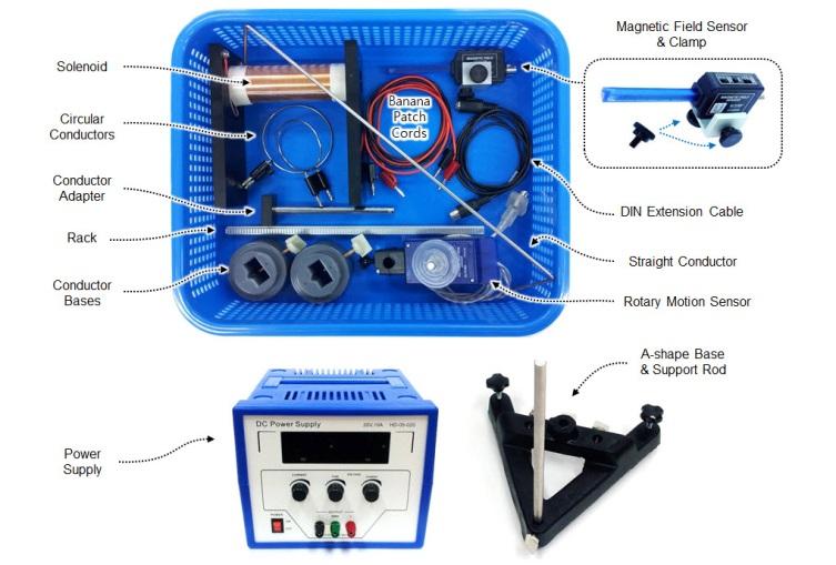
 Set up your equipment. Attach the Magnetic Field Sensor to one end of the Rack using the clamp.")
 (2) Set up the PASCO Capstone software.")
1 General Physics Lab Department of PHYSICS YONSEI University Lab Manual (Lite) Magnetic Fields Ver NOTICE This LITE version of manual includes only experimental procedures for easier reading on your smartphone. For more information and full instructions of the experiment, see the FULL version of manual. Magnetic Fields Procedure Experiment 1. Magnetic Field of a Straight Current-Carrying Conductor (1) Set up your equipment. Attach the Magnetic Field Sensor to one end of the Rack using the clamp. Insert the other end of the Rack to T-slot on the side of the Rotary Motion Sensor. (The teeth on the Rack go through the T-slot and then engage a pinion gear that is on the shaft of the sensor.) (2) Set up the PASCO Capstone software. 1 Run PASCO Capstone. 2 Add the Rotary Motion Sensor. Click [Hardware Setup] in the [Tools] palette. Confirm the panel shows the icon of the Rotary Motion Sensor. (In general, the interface automatically recognizes the Rotary Motion Sensor.)

![Select [Rotary Motion Sensor] from the list and the sensor s icon will be added to the panel.](/docs-images/89/99194268/images/2-1.jpg "3 Add the Magnetic Field Sensor.")
![Click the input port which you plugged the sensor into and select [Magnetic Field Sensor] from the](/docs-images/89/99194268/images/2-2.jpg "list. 4 Configure the Rotary Motion Sensor.")
![Click the Rotary Motion Sensor icon in the [Hardware Setup] panel and then click the properties](/docs-images/89/99194268/images/2-3.jpg "button ( ) in the lower right corner.")
![In the [Properties] window, select [Rack & Pinion] for [Linear Accessory].](/docs-images/89/99194268/images/2-4.jpg "[Change Sign] switches the sign on the sensor.")
2 If the sensor is not in the panel, click the input port which you plugged the sensor into. A drop down menu of sensors will appear. Select [Rotary Motion Sensor] from the list and the sensor s icon will be added to the panel. 3 Add the Magnetic Field Sensor. Click the input port which you plugged the sensor into and select [Magnetic Field Sensor] from the list. 4 Configure the Rotary Motion Sensor. Click the Rotary Motion Sensor icon in the [Hardware Setup] panel and then click the properties button ( ) in the lower right corner. In the [Properties] window, select [Rack & Pinion] for [Linear Accessory]. [Change Sign] switches the sign on the sensor. The sign of collected data depends on the setup status or rotational direction of the sensor shaft. Activate [Change Sign] if required. Confirm [Zero Sensor Measurements at Start] is activated. 5 Create a graph. Click and drag the [Graph] icon from the [Displays] palette into the workbook page. A graph display will appear.
] from the menu. 7 Configure the yy-axis of the graph.")
(T)] from the menu. (3) Set the magnetic field sensor.")
3 6 Configure the xx-axis of the graph. Set up the graph display to show the position of a measuring point on the xx-axis. Click <Select Measurement> on the vertical axis and pick [Rotary Motion Sensor] [Position(m)] from the menu. 7 Configure the yy-axis of the graph. Set up the graph display to show the magnitude of magnetic field on the yy-axis. Click <Select Measurement> on the horizontal axis and pick [Magnetic Field Sensor] [Magnetic Field Strength (100X)(T)] from the menu. (3) Set the magnetic field sensor. Orientation : [RADIAL] Range : [100X] (±10 3 T) [TARE] button is for zeroing the sensor. (4) Supply II = 5 A to the conductor. Before turning on the power supply, rotate the voltage and current adjustment knobs fully counterclockwise for no output settings. Turn on the power supply and rotate the voltage adjustment knob fully clockwise. Then set the current II through the conductor at 5 A by using the current adjustment knob. If you cannot obtain the desired output current: 1 Check the connections. Make sure the power supply is properly connected to the conductor. 2 Check if the CV lamp is on. It indicates that the DC output is in constant voltage mode, i.e. the voltage level you set is too low. Increase the voltage level by rotating the voltage adjustment knob clockwise.
 and then press the TARE button on top of")
.")
4 (5) Begin collecting data. Prior to any measurement, place the Magnetic Field Sensor away from any magnetic sources (current carrying conductor, power cables, and even your smartphone) and then press the TARE button on top of the sensor. Pressing the TARE zeroes the sensor at the value of the field it is reading at the moment the button pressed. That means your measurement of the field is not an absolute measurement, but a relative measurement (relative to the value of the field when you press the TARE button). Therefore, pressing the TARE under the influence of any magnetic field might cause spurious results of the experiment. For the best result, you should zero the sensor frequently, every time before each measurement. Click the [Record] button at the left end of the [Controls] palette to begin collecting data. Let the end of the probe touch the conductor (the white dot side of the probe must face up), and then slowly move the sensor away from the conductor, until the end of the probe is separated about 15cm from the conductor. (6) End the data collection. Click the [Stop] button to end the data collection. (7) Scale the graph. Adjust the scale of the graph automatically by clicking [Scale axes ] icon in the toolbar. You can also scale or pan the graph manually.
![(8) Analyze the graph. Click [Show coordinates ] to read off data points.](/docs-images/89/99194268/images/5-0.jpg "If you want to see more precise values of the collected data, you can use a table")


![[Curve Fitting] can be used to find a smooth function that approximately fits the](/docs-images/89/99194268/images/5-4.jpg "data. 1 Click [Select range ] in the toolbar and select a region of interest by")
5 (8) Analyze the graph. Click [Show coordinates ] to read off data points. If you want to see more precise values of the collected data, you can use a table display. Drag the [Table] icon into the workbook page, select appropriate measurements for each column, and then increase the number of digits by using the tool-bar icon as shown below. You may get a noisy curve due to the influence of external magnetic fields, unstable signal of the sensor, or your measurement skills. [Curve Fitting] can be used to find a smooth function that approximately fits the data. 1 Click [Select range ] in the toolbar and select a region of interest by resizing the rectangle. (Selected data is highlighted in yellow.) 2 Click [ ] of [Select curve fits ] and select the curve fit that you wish to apply to the selected data. 3 The fit function of the data will appear.

 Repeat your experiment. Repeat the steps (5)-(9) more than 5 times. (11) Analyze your results. BB = μμ 0II 2ππππ (8) rr (m) 0.01 0.02 0.03 0.04 0.")
6 (9) Record your data. Find the values of magnetic field BB on the graph at the distance rr = 0.01, 0.02, 0.03, 0.04, 0.05 m. The measured value at xx = 0 on the graph is NOT the magnetic field strength at rr = 0 of BB = μμ 0 II 2ππππ. The Hall sensor in the probe is at 8.5mm distance from the center of the conductor when the probe touches the conductor. This means that the value at xx = 0 on the graph is the magnetic field strength at rr = 8.5mm distance from the center of the conductor. (10) Repeat your experiment. Repeat the steps (5)-(9) more than 5 times. (11) Analyze your results. BB = μμ 0II 2ππππ (8) rr (m) st 2nd BB (T) 3rd 4th 5th BB aaaaaaaaaaaaaa BB ttheeeeeeee = μμ 0 II 2ππππ Experiment 2. Magnetic Field of a Circular Current Loop (1) Set up the equipment. Mount the circular conductor of radius aa = 0.03 m on the base using the Conductor Adapter.
 (3) Supply II = 5 A to the conductor.")


7 (2) Set the Magnetic Field Sensor. Orientation : [AXIAL] Range : [100X] (±10 3 T ) (3) Supply II = 5 A to the conductor. (4) Begin collecting data. Prior to any measurement, place the Magnetic Field Sensor away from any magnetic sources, and then press the TARE button on top of the sensor. For the best result, you should zero the sensor frequently, every time before each measurement. Slowly move the sensor along the axis of the circular conductor, keeping the probe parallel to the axis. (5) Analyze the graph. As already explained in previous experiment, [Curve Fitting] can be used to find a smooth function of your data. 1 Select [User Defined: f(x)]. 2 Click the curve fit legend. 3 [Curve Fit Editor] appears in the [Tools] palette.
![4 Enter your function and click [Apply].](/docs-images/89/99194268/images/8-0.jpg "μμ 0 IIaa 2 BB xx = 2(xx 2 + aa 2 ) 3 2 yy = AA aa 2 ((xx xx 0 ) 2 + aa 2 ) 3 2 + yy 0 y=a*a^2/((x-x0)^2+a^2)^(3/2)+y0 The fit function may not appear at the very moment.")
![In this case, you need to enter the values in the [Initial Guess] boxes to modify the function. 1) Click [Lock] check box next to the radius aa = 0.03 m to lock this entry.](/docs-images/89/99194268/images/8-2.jpg "2) Enter (xx 0, yy 0 ) = (0.06, 0), since the fit ff(xx xx 0 ) + yy 0 is shifted to the right about (0.06, 0) from ff(xx), as shown the graph above. (It depends on your data.). 3) You can also enter the calculated value of A = μμ 0 II/2.")
![(You don t have to enter all initial guesses.) 4) Click [Update Fit]. 5 The fit function of the data will appear. (6) Record your data.](/docs-images/89/99194268/images/8-3.jpg "Find the values of magnetic field BB on the graph at the point xx = 0.00, 0.01, 0.02, 0.03, 0.04 m. (The maximum value of the graph is the field strength of the conductor center.")
8 4 Enter your function and click [Apply]. μμ 0 IIaa 2 BB xx = 2(xx 2 + aa 2 ) 3 2 yy = AA aa 2 ((xx xx 0 ) 2 + aa 2 ) yy 0 y=a*a^2/((x-x0)^2+a^2)^(3/2)+y0 The fit function may not appear at the very moment. In this case, you need to enter the values in the [Initial Guess] boxes to modify the function. 1) Click [Lock] check box next to the radius aa = 0.03 m to lock this entry. 2) Enter (xx 0, yy 0 ) = (0.06, 0), since the fit ff(xx xx 0 ) + yy 0 is shifted to the right about (0.06, 0) from ff(xx), as shown the graph above. (It depends on your data.). 3) You can also enter the calculated value of A = μμ 0 II/2. (You don t have to enter all initial guesses.) 4) Click [Update Fit]. 5 The fit function of the data will appear. (6) Record your data. Find the values of magnetic field BB on the graph at the point xx = 0.00, 0.01, 0.02, 0.03, 0.04 m. (The maximum value of the graph is the field strength of the conductor center.) (7) Repeat your experiment. Repeat the steps (4)-(5) more than 5 times. μμ 0 IIaa 2 BB xx = 2(xx 2 + aa 2 ) 3 (12) 2 xx (m) st 2nd BB (T) 3rd 4th 5th BB aaaaaaaaaaaaaa BB ttheeeeeeee (8) Repeat the experiment using the circular conductor of radius aa = 0.04 m.
 Set up the data acquisition software. 1 Add sensors.")

![2 Configure a current output. Click [Signal Generator] in the [Tools] palette and select [850 Output 1].](/docs-images/89/99194268/images/9-2.jpg "[Waveform] : DC [DC Voltage] : 10V [Auto] automatically starts/stops the signal generator when the interface")
] yy-axis : [Magnetic Field Strength (10X) (T)] 4 Create a digital meter.")
9 Experiment 3. Magnetic field of a solenoid (1) Set up the equipment. We will use the built-in power supply of the interface. (2) Set up the data acquisition software. 1 Add sensors. Add the Rotary Motion Sensor and the Magnetic Field Sensor as explained in previous experiments. In addition, add [Output Voltage Current Sensor] by clicking the output port which you connected the solenoid to. 2 Configure a current output. Click [Signal Generator] in the [Tools] palette and select [850 Output 1]. [Waveform] : DC [DC Voltage] : 10V [Auto] automatically starts/stops the signal generator when the interface starts/stops recording data. 3 Create a graph. xx-axis : [Position(m)] yy-axis : [Magnetic Field Strength (10X) (T)] 4 Create a digital meter. Create a digital meter to measure the current through the solenoid. Drag the [Digits] icon from the [Displays] palette into the workbook page, and select [Output Current (A)] for the measurement.
![(3) Set the Magnetic Field Sensor. Orientation : [AXIAL] Range : [10X] (±10 2 T ) [TARE] button is used to zero the sensor (4) Begin collecting data.](/docs-images/89/99194268/images/10-0.jpg "Put the sensor inside the solenoid and measure the magnetic field all over the inside and outside of the solenoid, keeping the sensor probe parallel to the axis of the solenoid. (5) Analyze the graph.")
 Record and analyze your results.")
10 (3) Set the Magnetic Field Sensor. Orientation : [AXIAL] Range : [10X] (±10 2 T ) [TARE] button is used to zero the sensor (4) Begin collecting data. Put the sensor inside the solenoid and measure the magnetic field all over the inside and outside of the solenoid, keeping the sensor probe parallel to the axis of the solenoid. (5) Analyze the graph. Read the current through the solenoid from the digital meter. If the graph shows the values of magnetic field as zero, you can see precise values using a table display. Drag the [Table] icon display into the workbook page, select measurements for each column, and then increase the number of digits by using the icon as shown below. (6) Record and analyze your results. Repeat the steps (4)-(5) more than 5 times and find the values of magnetic field BB at the center and edge of the solenoid. (See note of the next page.) BB = 1 2 μμ xx 0nnnn xx 2 + aa + LL xx 2 (15) (LL xx) 2 + aa2 center end 1st 2nd BB (T) 3rd 4th 5th BB aaaaaaaaaaaaaa BB ttheeeeeeee
![Use [Curve Fitting] to find the values of magnetic field at center or at edge of the solenoid. Enter your function and click [Apply].](/docs-images/89/99194268/images/11-0.jpg "BB = 1 2 μμ xx 0nnnn xx 2 + aa + LL xx 2 (LL xx) 2 + aa 2 (xx xx yy = A 0 ) (xx xx 0 ) 2 + aa + LL (xx xx 0 ) + yy 0 2 LL (xx xx 0 ) 2 + aa 2 y=a*((x-x0)/((x-x0)^2+a^2)^(1/2)+ (0.13-(x-x0))/((0.")
![13-(x-x0))^2+a^2)^(1/2))+y0 Click [Lock] check box next to the radius aa = 0.0195 m to lock this entry. Enter the calculated value of A = μμ 0 nnnn/2 if required.](/docs-images/89/99194268/images/11-1.jpg "The origin of ff(xx) is on the point O (left end of the solenoid) as shown below.")
11 Use [Curve Fitting] to find the values of magnetic field at center or at edge of the solenoid. Enter your function and click [Apply]. BB = 1 2 μμ xx 0nnnn xx 2 + aa + LL xx 2 (LL xx) 2 + aa 2 (xx xx yy = A 0 ) (xx xx 0 ) 2 + aa + LL (xx xx 0 ) + yy 0 2 LL (xx xx 0 ) 2 + aa 2 y=a*((x-x0)/((x-x0)^2+a^2)^(1/2)+ (0.13-(x-x0))/((0.13-(x-x0))^2+a^2)^(1/2))+y0 Click [Lock] check box next to the radius aa = m to lock this entry. Enter the calculated value of A = μμ 0 nnnn/2 if required. The origin of ff(xx) is on the point O (left end of the solenoid) as shown below. If you insert the sensor into the right side of the solenoid, the measuring point of the probe may reach near the center (0.130/2 = 0.065m) of the solenoid. Thus, the fit ff(xx xx 0 ) + yy 0 is shifted about ( 0.065, 0) from ff(xx). Enter the initial guesses (xx 0, yy 0 ) = ( 0.065, 0) and Click [Update Fit]. The fit function of the data will appear. The fit value xx 0 = shows that the point O (left end of the solenoid) is on xx left = of the graph. (This depends on your result.) Since the length of the solenoid is LL = 0.130m, the center of the solenoid is on xx center = = and the right edge of the solenoid is on xx right = = of the graph. End of LAB Checklist Please put your equipment in order as shown below. Delete your data files from the lab computer. Turn off the Computer and the Interface. With the voltage and current adjustment knobs set at zero, turn off the power supply and unplug the power cable. Handle the solenoid carefully to avoid scratching or stabbing the coils. Do not disassemble the Magnetic Field Sensor assembly.
12
Physical Pendulum Torsion Pendulum
 General Physics Lab Department of PHYSICS YONSEI University Lab Manual (Lite) Physical Pendulum / Torsion Pendulum Ver.20180424 NOTICE This LITE version of manual includes only experimental procedures
Circular Motion and Centripetal Force
 [For International Campus Lab ONLY] Objective Measure the centripetal force with the radius, mass, and speed of a particle in uniform circular motion. Theory ----------------------------- Reference --------------------------
Free Fall and Projectile Motion
 [International Campus] Free Fall and Projectile Motion Objective Investigate the motions of a freely falling body and a projectile under the influence of gravity. Find the acceleration due to gravity.
Activity P20: Conservation of Mechanical Energy (Force Sensor, Photogate)
") Name Class Date Activity P20: Conservation of Mechanical Energy (Force Sensor, Photogate) Concept DataStudio ScienceWorkshop (Mac) ScienceWorkshop (Win) Energy P20 Mechanical Energy.DS P23 Cons. Mechanical
Name Class Date Activity P20: Conservation of Mechanical Energy (Force Sensor, Photogate) Concept DataStudio ScienceWorkshop (Mac) ScienceWorkshop (Win) Energy P20 Mechanical Energy.DS P23 Cons. Mechanical
Developing a Scientific Theory
 Name Date Developing a Scientific Theory Equipment Needed Qty Equipment Needed Qty Photogate/Pulley System (ME-6838) 1 String (SE-8050) 1 Mass and Hanger Set (ME-8967) 1 Universal Table Clamp (ME-9376B)
Physical Pendulum, Torsion Pendulum
 [International Campus Lab] Physical Pendulum, Torsion Pendulum Objective Investigate the motions of physical pendulums and torsion pendulums. Theory ----------------------------- Reference --------------------------
Determination of the Equivalent Weight and the K a or K b for a Weak Acid or Base
 INTRODUCTION Determination of the Equivalent Weight and the K a or K b for a Weak Acid or Base Chemists frequently make use of the equivalent weight (eq. wt.) as the basis for volumetric calculations.
Kinematics. Become comfortable with the data aquisition hardware and software used in the physics lab.
 Kinematics Objective Upon completing this experiment you should Become comfortable with the data aquisition hardware and software used in the physics lab. Have a better understanding of the graphical analysis
General Physics I Lab (PHYS-2011) Experiment MECH-2: Newton's Second Law
 Experiment MECH-2: Newton's Second Law") MECH-2: Newton's Second Law Page 1 of 5 1 EQUIPMENT General Physics I Lab (PHYS-2011) Experiment MECH-2: Newton's Second Law 1 250 g Stackable Masses (set of 2) ME-6757A 1 Smart Cart Blue ME-1241 1 Mass
MECH-2: Newton's Second Law Page 1 of 5 1 EQUIPMENT General Physics I Lab (PHYS-2011) Experiment MECH-2: Newton's Second Law 1 250 g Stackable Masses (set of 2) ME-6757A 1 Smart Cart Blue ME-1241 1 Mass
Activity P60: Inverse Square Law Nuclear (Nuclear Sensor, Rotary Motion Sensor)
") Name Class Date Activity P60: Inverse Square Law Nuclear (Nuclear Sensor, Rotary Motion Sensor) Concept DataStudio ScienceWorkshop (Mac) ScienceWorkshop (Win) Radioactivity P60 Nuclear Inv Sqr Law.DS P60
Name Class Date Activity P60: Inverse Square Law Nuclear (Nuclear Sensor, Rotary Motion Sensor) Concept DataStudio ScienceWorkshop (Mac) ScienceWorkshop (Win) Radioactivity P60 Nuclear Inv Sqr Law.DS P60
Activity P11: Collision Impulse and Momentum (Force Sensor, Motion Sensor)
") Name Class Date Activity P11: Collision Impulse and Momentum (Force Sensor, Motion Sensor) Concept DataStudio ScienceWorkshop (Mac) ScienceWorkshop (Win) Newton s Laws P11 Impulse.DS P14 Collision P14_COLL.SWS
Name Class Date Activity P11: Collision Impulse and Momentum (Force Sensor, Motion Sensor) Concept DataStudio ScienceWorkshop (Mac) ScienceWorkshop (Win) Newton s Laws P11 Impulse.DS P14 Collision P14_COLL.SWS
Name Class Date. RC Circuit Lab
 RC Circuit Lab Objectives: Students will be able to Use the ScienceWorkshop interface to investigate the relationship between the voltage remaining across a capacitor and the time taken for the discharge
Human Arm. 1 Purpose. 2 Theory. 2.1 Equation of Motion for a Rotating Rigid Body
 Human Arm Equipment: Capstone, Human Arm Model, 45 cm rod, sensor mounting clamp, sensor mounting studs, 2 cord locks, non elastic cord, elastic cord, two blue pasport force sensors, large table clamps,
Rotational Motion. 1 Purpose. 2 Theory 2.1 Equation of Motion for a Rotating Rigid Body
 Rotational Motion Equipment: Capstone, rotary motion sensor mounted on 80 cm rod and heavy duty bench clamp (PASCO ME-9472), string with loop at one end and small white bead at the other end (125 cm bead
Physics Labs with Computers, Vol. 1 P14: Simple Harmonic Motion - Mass on a Spring A
 Activity P14: Simple Harmonic Motion - Mass on a Spring (Force Sensor, Motion Sensor) Concept DataStudio ScienceWorkshop (Mac) ScienceWorkshop (Win) Harmonic motion P14 SHM.DS P19 SHM Mass on a Spring
Lab 10 Circular Motion and Centripetal Acceleration
 Lab 10 Circular Motion and Centripetal Equipment Calculator, Computer, PASCO 850 Universal Interface Partially-assembled Centripetal Force Apparatus Photogate Cable Pair of Banana Wires Objective Verify
vv d of the electrons. As a result, there is a net current in
 [International Campus] Objective Investigate the effects of current, length of wire and magnetic field strength on a magnetic force. Theory ----------------------------- Reference --------------------------
Activity P27: Speed of Sound in Air (Sound Sensor)
") Activity P27: Speed of Sound in Air (Sound Sensor) Concept Speed of sound DataStudio P27 Speed of Sound 1.DS Equipment Needed Qty Other Qty Sound Sensor (CI-6506B) 1 Tape, duct 1 roll Base and Support
Activity P27: Speed of Sound in Air (Sound Sensor) Concept Speed of sound DataStudio P27 Speed of Sound 1.DS Equipment Needed Qty Other Qty Sound Sensor (CI-6506B) 1 Tape, duct 1 roll Base and Support
Activity P15: Simple Harmonic Oscillation (Force Sensor, Photogate)
") Activity P15: Simple Harmonic Oscillation (Force Sensor, Photogate) Concept DataStudio ScienceWorkshop (Mac) ScienceWorkshop (Win) Harmonic motion P15 Oscillation.DS P21 Harmonic Oscillation P21_HARM.SWS
Activity P15: Simple Harmonic Oscillation (Force Sensor, Photogate) Concept DataStudio ScienceWorkshop (Mac) ScienceWorkshop (Win) Harmonic motion P15 Oscillation.DS P21 Harmonic Oscillation P21_HARM.SWS
Experiment 19: The Current Balance
 Experiment 19: The Current Balance Figure 19.1: Current Balance Arrangement for Varying Current or Length From Left to Right: Power Supply, Current Balance Assembly, Ammeter (20A DCA scale, 20A jack).
Lab 8: Magnetic Fields
 Lab 8: Magnetic Fields Name: Group Members: Date: TA s Name: Objectives: To measure and understand the magnetic field of a bar magnet. To measure and understand the magnetic field of an electromagnet,
Activity P08: Newton's Second Law - Constant Force (Force Sensor, Motion Sensor)
") Activity P08: Newton's Second Law - Constant Force (Force Sensor, Motion Sensor) Concept DataStudio ScienceWorkshop (Mac) ScienceWorkshop (Win) Newton s Laws P08 Constant Force.DS P11 Constant Force P11_CONF.SWS
Activity P08: Newton's Second Law - Constant Force (Force Sensor, Motion Sensor) Concept DataStudio ScienceWorkshop (Mac) ScienceWorkshop (Win) Newton s Laws P08 Constant Force.DS P11 Constant Force P11_CONF.SWS
( ) ( ) = q o. T 12 = τ ln 2. RC Circuits. 1 e t τ. q t
 ( ) = q o. T 12 = τ ln 2. RC Circuits. 1 e t τ. q t") Objectives: To explore the charging and discharging cycles of RC circuits with differing amounts of resistance and/or capacitance.. Reading: Resnick, Halliday & Walker, 8th Ed. Section. 27-9 Apparatus:
Objectives: To explore the charging and discharging cycles of RC circuits with differing amounts of resistance and/or capacitance.. Reading: Resnick, Halliday & Walker, 8th Ed. Section. 27-9 Apparatus:
Lab 1 Uniform Motion - Graphing and Analyzing Motion
 Lab 1 Uniform Motion - Graphing and Analyzing Motion Objectives: < To observe the distance-time relation for motion at constant velocity. < To make a straight line fit to the distance-time data. < To interpret
Collisions Impulse and Momentum
 rev 06/2017 Collisions Impulse and Momentum Equipment Qty Items Part Number 1 Collision Cart ME-9454 1 Dynamics Track ME-9493 1 Force Sensor CI-6746 1 Motion Sensor II CI-6742A 1 Accessory Bracket CI-6545
Experiment P30: Centripetal Force on a Pendulum (Force Sensor, Photogate)
") PASCO scientific Physics Lab Manual: P30-1 Experiment P30: (Force Sensor, Photogate) Concept Time SW Interface Macintosh File Windows File centripetal force 30 m 500 or 700 P30 Centripetal Force P30_CENT.SWS
PASCO scientific Physics Lab Manual: P30-1 Experiment P30: (Force Sensor, Photogate) Concept Time SW Interface Macintosh File Windows File centripetal force 30 m 500 or 700 P30 Centripetal Force P30_CENT.SWS
Physics Spring 2006 Experiment 4. Centripetal Force. For a mass M in uniform circular motion with tangential speed v at radius R, the required
 Centripetal Force I. Introduction. In this experiment you will study the centripetal force required for a mass in uniform circular motion. You will determine the centripetal forces required for different
Old Dominion University Physics 112N/227N/232N Lab Manual, 13 th Edition
 RC Circuits Experiment PH06_Todd OBJECTIVE To investigate how the voltage across a capacitor varies as it charges. To find the capacitive time constant. EQUIPMENT NEEDED Computer: Personal Computer with
The University of Hong Kong Department of Physics. Physics Laboratory PHYS3350 Classical Mechanics Experiment No The Physical Pendulum Name:
 The University of Hong Kong Department of Physics Physics Laboratory PHYS3350 Classical Mechanics Experiment No. 3350-2 The Physical Pendulum Name: University No: Introduction One of the practical uses
Driven Harmonic Oscillator
 Driven Harmonic Oscillator Physics 6B Lab Experiment 1 APPARATUS Computer and interface Mechanical vibrator and spring holder Stands, etc. to hold vibrator Motion sensor C-209 spring Weight holder and
Never switch on the equipment without the assistants explicit authorization!
 Biot Savart s law 1 Objective The objective of this experiment is to verify Biot-Savart s law for certain geometries. Over the course of the preparation, the actual experiment and the writing of the report
LAB 2 - ONE DIMENSIONAL MOTION
 Name Date Partners L02-1 LAB 2 - ONE DIMENSIONAL MOTION OBJECTIVES Slow and steady wins the race. Aesop s fable: The Hare and the Tortoise To learn how to use a motion detector and gain more familiarity
Electrostatic Charge Distribution (Charge Sensor)
") 65 Electrostatic Charge Distribution (Charge Sensor) E&M: Electrostatic charge distribution Equipment List DataStudio file: 65 Charge Distribution.ds Qty Items Part Numbers 1 PASCO Interface (for one sensor)
65 Electrostatic Charge Distribution (Charge Sensor) E&M: Electrostatic charge distribution Equipment List DataStudio file: 65 Charge Distribution.ds Qty Items Part Numbers 1 PASCO Interface (for one sensor)
Lab: Newton s Second Law
 Ph4_ConstMass2ndLawLab Page 1 of 9 Lab: Newton s Second Law Constant Mass Equipment Needed Qty Equipment Needed Qty 1 Mass and Hanger Set (ME-8967) 1 Motion Sensor (CI-6742) 1 String (SE-8050) 1 m Balance
Experiment P05: Position, Velocity, & Acceleration (Motion Sensor)
") PASCO scientific Physics Lab Manual: P05-1 Experiment P05: Position, Velocity, & Acceleration (Motion Sensor) Concept Time SW Interface Macintosh file Windows file linear motion 30 m 500 or 700 P05 Position,
PASCO scientific Physics Lab Manual: P05-1 Experiment P05: Position, Velocity, & Acceleration (Motion Sensor) Concept Time SW Interface Macintosh file Windows file linear motion 30 m 500 or 700 P05 Position,
EXPERIMENT : Work and Energy. Topics of investigation: The relation between force and acceleration
 EXPERIMENT 2000031: Work and Energy Topics of investigation: The relation between force and acceleration Read about this topic in: Serway, Ch 7, 8; C&J Ch 6 Toolkit: Computer Laboratory interface & software
Safety: BE SURE TO KEEP YOUR SMART CART UPSIDE-DOWN WHEN YOU RE NOT ACTIVELY USING IT TO RECORD DATA.
 Why do people always ignore Objective: 1. Determine how an object s mass affects the friction it experiences. 2. Compare the coefficient of static friction to the coefficient of kinetic friction for each
HB Coupled Pendulums Lab Coupled Pendulums
 HB 04-19-00 Coupled Pendulums Lab 1 1 Coupled Pendulums Equipment Rotary Motion sensors mounted on a horizontal rod, vertical rods to hold horizontal rod, bench clamps to hold the vertical rods, rod clamps
Electric Field Mapping (approx. 2 h 15 min.) (8/8/2018)
 (8/8/2018)") Electric Field Mapping (approx. 2 h 15 min.) (8/8/2018) Equipment shallow glass pan pitcher for water masking tape graph paper (8.5 x14 ) colored pencils metal shapes sand paper paper towels DC power supply
Electric Field Mapping (approx. 2 h 15 min.) (8/8/2018) Equipment shallow glass pan pitcher for water masking tape graph paper (8.5 x14 ) colored pencils metal shapes sand paper paper towels DC power supply
Newton's 2 nd Law. . Your end results should only be interms of m
 Newton's nd Law Introduction: In today's lab you will demonstrate the validity of Newton's Laws in predicting the motion of a simple mechanical system. The system that you will investigate consists of
M61 1 M61.1 PC COMPUTER ASSISTED DETERMINATION OF ANGULAR ACCELERATION USING TORQUE AND MOMENT OF INERTIA
 M61 1 M61.1 PC COMPUTER ASSISTED DETERMINATION OF ANGULAR ACCELERATION USING TORQUE AND MOMENT OF INERTIA PRELAB: Before coming to the lab, you must write the Object and Theory sections of your lab report
You will return this handout to the instructor at the end of the lab period. Experimental verification of Ampere s Law.
 PHY222 LAB 6 AMPERE S LAW Print Your Name Print Your Partners' Names Instructions Read section A prior to attending your lab section. You will return this handout to the instructor at the end of the lab
PHY222 Lab 2 - Electric Fields Mapping the Potential Curves and Field Lines of an Electric Dipole
 Print Your Name PHY222 Lab 2 - Electric Fields Mapping the Potential Curves and Field Lines of an Electric Dipole Print Your Partners' Names Instructions January 23, 2015 Before lab, read the Introduction,
Physics Labs with Computers, Vol. 1 P23: Conservation of Angular Momentum A
 Activity P23: Conservation of Angular Momentum (Rotary Motion Sensor) Concept DataStudio ScienceWorkshop (Mac) ScienceWorkshop (Win) Rotational motion P23 Angular Momentum.DS (See end of activity) (See
Experiment P14: Collision Impulse & Momentum (Force Sensor, Motion Sensor)
") PASCO scientific Physics Lab Manual: P14-1 Experiment P14: (Force Sensor, Motion Sensor) Concept Time SW Interface Macintosh file Windows file Newton s Laws 45 m 500 or 700 P14 Collision P14_COLL.SWS EQUIPMENT
PASCO scientific Physics Lab Manual: P14-1 Experiment P14: (Force Sensor, Motion Sensor) Concept Time SW Interface Macintosh file Windows file Newton s Laws 45 m 500 or 700 P14 Collision P14_COLL.SWS EQUIPMENT
Experiment P43: RC Circuit (Power Amplifier, Voltage Sensor)
") PASCO scientific Vol. 2 Physics Lab Manual: P43-1 Experiment P43: (Power Amplifier, Voltage Sensor) Concept Time SW Interface Macintosh file Windows file circuits 30 m 700 P43 P43_RCCI.SWS EQUIPMENT NEEDED
PASCO scientific Vol. 2 Physics Lab Manual: P43-1 Experiment P43: (Power Amplifier, Voltage Sensor) Concept Time SW Interface Macintosh file Windows file circuits 30 m 700 P43 P43_RCCI.SWS EQUIPMENT NEEDED
Representations of Motion in One Dimension: Speeding up and slowing down with constant acceleration
 Representations of Motion in One Dimension: Speeding up and slowing down with constant acceleration Name: Group Members: Date: TA s Name: Apparatus: Aluminum track and supports, PASCO Smart Cart, two cart
RC Circuit (Power amplifier, Voltage Sensor)
") Object: RC Circuit (Power amplifier, Voltage Sensor) To investigate how the voltage across a capacitor varies as it charges and to find its capacitive time constant. Apparatus: Science Workshop, Power
Object: RC Circuit (Power amplifier, Voltage Sensor) To investigate how the voltage across a capacitor varies as it charges and to find its capacitive time constant. Apparatus: Science Workshop, Power
Newton s Second Law. Computer with Capstone software, motion detector, PVC pipe, low friction cart, track, meter stick.
 F = m a F = m a Newton s Second Law 1 Object To investigate, understand and verify the relationship between an object s acceleration and the net force acting on that object as well as further understand
Magnetic field of single coils/ Biot-Savart s law with Cobra4
 Magnetic field of single coils/ TEP Related topics Wire loop, Biot-Savart s law, Hall effect, magnetic field, induction, magnetic flux density. Principle The magnetic field along the axis of wire loops
Experiment P09: Acceleration of a Dynamics Cart I (Smart Pulley)
") PASCO scientific Physics Lab Manual: P09-1 Experiment P09: (Smart Pulley) Concept Time SW Interface Macintosh file Windows file Newton s Laws 30 m 500 or 700 P09 Cart Acceleration 1 P09_CAR1.SWS EQUIPMENT
PASCO scientific Physics Lab Manual: P09-1 Experiment P09: (Smart Pulley) Concept Time SW Interface Macintosh file Windows file Newton s Laws 30 m 500 or 700 P09 Cart Acceleration 1 P09_CAR1.SWS EQUIPMENT
Activity P10: Atwood's Machine (Photogate/Pulley System)
") Name Class Date Activity P10: Atwood's Machine (Photogate/Pulley System) Concept DataStudio ScienceWorkshop (Mac) ScienceWorkshop (Win) Newton's Laws P10 Atwood s.ds P13 Atwood's Machine P13_ATWD.SWS Equipment
Name Class Date Activity P10: Atwood's Machine (Photogate/Pulley System) Concept DataStudio ScienceWorkshop (Mac) ScienceWorkshop (Win) Newton's Laws P10 Atwood s.ds P13 Atwood's Machine P13_ATWD.SWS Equipment
Experiment P17: Conservation of Linear Momentum II (Photogate)
") PASCO scientific Physics Lab Manual: P17-1 Experiment P17: Conservation of Linear Momentum II (Photogate) Concept Time SW Interface Macintosh file Windows file Newton s Laws 45 m 500 or 700 P17 Cons. of
PASCO scientific Physics Lab Manual: P17-1 Experiment P17: Conservation of Linear Momentum II (Photogate) Concept Time SW Interface Macintosh file Windows file Newton s Laws 45 m 500 or 700 P17 Cons. of
Newton s Second Law. Sample
 Newton s Second Law Experiment 4 INTRODUCTION In your discussion of Newton s first law, you learned that when the sum of the forces acting on an object is zero, its velocity does not change. However, when
Constant velocity and constant acceleration
 Constant velocity and constant acceleration Physics 110 Laboratory Introduction In this experiment we will investigate two rather simple forms of motion (kinematics): motion with uniform (non-changing)
PHY221 Lab 2 - Experiencing Acceleration: Motion with constant acceleration; Logger Pro fits to displacement-time graphs
 Page 1 PHY221 Lab 2 - Experiencing Acceleration: Motion with constant acceleration; Logger Pro fits to displacement-time graphs Print Your Name Print Your Partners' Names You will return this handout to
Second Law. In this experiment you will verify the relationship between acceleration and force predicted by Newton s second law.
 Second Law Objective In this experiment you will verify the relationship between acceleration and force predicted by Newton s second law. Apparatus Table clamp, Vertical rod, Right-angle clamp, Horizontal
LAB 5: Induction: A Linear Generator
 1 Name Date Partner(s) OBJECTIVES LAB 5: Induction: A Linear Generator To understand how a changing magnetic field induces an electric field. To observe the effect of induction by measuring the generated
EE 3324 Electromagnetics Laboratory
 EE 3324 Electromagnetics Laboratory Experiment #3 Inductors and Inductance 1. Objective The objective of Experiment #3 is to investigate the concepts of inductors and inductance. Several inductor geometries
Harmonic Motion. Mass on a Spring. Physics 231: General Physics I Lab 6 Mar. 11, Goals:
 Physics 231: General Physics I Lab 6 Mar. 11, 2004 Names: Harmonic Motion Goals: 1. To learn about the basic characteristics of periodic motion period, frequency, and amplitude 2. To study what affects
MAG Magnetic Fields revised May 27, 2017
 MAG Magnetic Fields revised May 7, 017 (You will do two experiments; this one (in Rock 40) and the Magnetic Induction experiment (in Rock 403). Sections will switch rooms and experiments half-way through
Electric Field and Electric Potential
 Electric Field and Electric Potential INTRODUCTION Physicists use the concept of a field 1 to explain the interaction of particles or bodies through space, i.e., the action-at-a-distance 2 force between
Exp. #2-4 : Measurement of Characteristics of Magnetic Fields by Using Single Coils and a Computer Interface
 PAGE 1/17 Exp. #2-4 : Measurement of Characteristics of Magnetic Fields by Using Single Coils and a Computer Interface Student ID Major Name Team No. Experiment Lecturer Student's Mentioned Items Experiment
Rotary Motion Sensor
 Instruction Manual Manual No. 012-06053B Rotary Motion Sensor Experiment 1: Rotational Inertia of a Point Mass Equipment Required ScienceWorkshop 750 Interface (CI- 6450 or CI-7599) Mini-Rotational Accessory
Newton s Second Law. Newton s Second Law of Motion describes the results of a net (non-zero) force F acting on a body of mass m.
 force F acting on a body of mass m.") Newton s Second Law Newton s Second Law of Motion describes the results of a net (non-zero) force F acting on a body of mass m. F net = ma (1) It should come as no surprise that this force produces an
Newton s Second Law Newton s Second Law of Motion describes the results of a net (non-zero) force F acting on a body of mass m. F net = ma (1) It should come as no surprise that this force produces an
Conservation of Momentum Using PASCO TM Carts and Track to Study Collisions in One Dimension
 14 Conservation of Conservation of Using PASCO TM Carts and Track to Study s in One Dimension When two objects collide momentum is transferred between them. p is defined as the product of mass and velocity
Lab 10: DC RC circuits
 Name: Lab 10: DC RC circuits Group Members: Date: TA s Name: Objectives: 1. To understand current and voltage characteristics of a DC RC circuit 2. To understand the effect of the RC time constant Apparatus:
Electricity. Measuring the force on current-carrying conductors in a homogeneous magnetic field. LEYBOLD Physics Leaflets P
 Electricity Magnetostatics The effects of force in a magnetic field LEYBOLD Physics Leaflets Measuring the force on current-carrying conductors in a homogeneous magnetic field Recording with CASSY Objects
Hooke s Law. Equipment. Introduction and Theory
 Hooke s Law Objective to test Hooke s Law by measuring the spring constants of different springs and spring systems to test whether all elastic objects obey Hooke s Law Equipment two nearly identical springs,
Possible Prelab Questions.
 Possible Prelab Questions. Read Lab 2. Study the Analysis section to make sure you have a firm grasp of what is required for this lab. 1) A car is travelling with constant acceleration along a straight
Acceleration/Velocity/Displacement VIBRATION METER
 Acceleration/Velocity/Displacement VIBRATION METER Model : VB-8220 Your purchase of this VIBRATION METER marks a step forward for you into the field of precision measurement. Although this METER is a complex
Ballistic Pendulum. Equipment. Introduction. Setup
 35 Ballistic Pendulum 35 - Page 1 of 5 Equipment Ballistic Pendulum 1 Rotary Motion Sensor PS-2120A 2 Photogate Head ME-9498A 1 Mounting Bracket ME-6821A 1 Large Table Clamp ME-9472 1 90 cm rod ME-8738
Experiment 11: Rotational Inertia of Disk and Ring
 Experiment 11: Rotational Inertia of Disk and Ring Equipment Required ScienceWorkshop 750 Interface (CI- 6450 or CI-7599) Mini-Rotational Accessory (CI-6691) Base and Support Rod (ME-9355) Paper clips
E X P E R I M E N T 11
 E X P E R I M E N T 11 Conservation of Angular Momentum Produced by the Physics Staff at Collin College Copyright Collin College Physics Department. All Rights Reserved. University Physics, Exp 11: Conservation
The Damped Pendulum. Physics 211 Lab 3 3/18/2016
 PHYS11 Lab 3 Physics 11 Lab 3 3/18/16 Objective The objective of this lab is to record the angular position of the pendulum vs. time with and without damping. The data is then analyzed and compared to
Computer simulation of radioactive decay
 Computer simulation of radioactive decay y now you should have worked your way through the introduction to Maple, as well as the introduction to data analysis using Excel Now we will explore radioactive
Linear Motion with Constant Acceleration
 Linear Motion 1 Linear Motion with Constant Acceleration Overview: First you will attempt to walk backward with a constant acceleration, monitoring your motion with the ultrasonic motion detector. Then
EXPERIMENT 7: ANGULAR KINEMATICS AND TORQUE (V_3)
") TA name Lab section Date TA Initials (on completion) Name UW Student ID # Lab Partner(s) EXPERIMENT 7: ANGULAR KINEMATICS AND TORQUE (V_3) 121 Textbook Reference: Knight, Chapter 13.1-3, 6. SYNOPSIS In
TA name Lab section Date TA Initials (on completion) Name UW Student ID # Lab Partner(s) EXPERIMENT 7: ANGULAR KINEMATICS AND TORQUE (V_3) 121 Textbook Reference: Knight, Chapter 13.1-3, 6. SYNOPSIS In
General Physics I Lab. M1 The Atwood Machine
 Purpose General Physics I Lab In this experiment, you will learn the basic operation of computer interfacing and use it in an experimental study of Newton s second law. Equipment and components Science
Impulse, Momentum, and Energy
 Impulse, Momentum, and Energy Impulse, Momentum, and Energy 5-1 INTRODUCTION Newton expressed what we now call his second law of motion, 1 not as F = m a, but in terms of the rate of change of momentum
Exp. P-6 Blackbody Radiation
 Exp. P-6 Blackbody Radiation Updated Feb 2019 by A. Azelis, M. Hohlmann Equipment Prism Spectrophotometrer Kit Optics Bench (60 cm) Spectrophotometer Accessory Kit Aperture Bracket High Sensitivity Light
MASSACHUSETTS INSTITUTE OF TECHNOLOGY Physics Department. Experiment 03: Work and Energy
 MASSACHUSETTS INSTITUTE OF TECHNOLOGY Physics Department Physics 8.01 Fall Term 2010 Experiment 03: Work and Energy Purpose of the Experiment: In this experiment you allow a cart to roll down an inclined
Lasentec Product Group
 Document Number: 004-0043 Window Reference Procedure - M500/600 P Probes, version 6.0 and higher FBRM CI Software The Window Reference Procedure is the standard calibration procedure used to reference
Name Class Date. Activity P21: Kinetic Friction (Photogate/Pulley System)
") Name Class Date Activity P21: Kinetic Friction (Photogate/Pulley System) Concept DataStudio ScienceWorkshop (Mac) ScienceWorkshop (Win) Newton s Laws P21 Kinetic Friction.DS P25 Kinetic Friction P25_KINE.SWS
Name Class Date Activity P21: Kinetic Friction (Photogate/Pulley System) Concept DataStudio ScienceWorkshop (Mac) ScienceWorkshop (Win) Newton s Laws P21 Kinetic Friction.DS P25 Kinetic Friction P25_KINE.SWS
Experiment P13: Atwood's Machine (Smart Pulley)
") PASCO scientific Physics Lab Manual: P13-1 Experiment P13: Atwood's Machine (Smart Pulley) Concept Time SW Interface Macintosh file Windows file Newton's Laws 45 m 500 or 700 P13 Atwood's Machine P13_ATWD.SWS
PASCO scientific Physics Lab Manual: P13-1 Experiment P13: Atwood's Machine (Smart Pulley) Concept Time SW Interface Macintosh file Windows file Newton's Laws 45 m 500 or 700 P13 Atwood's Machine P13_ATWD.SWS
Physics 1020 Experiment 6. Equilibrium of a Rigid Body
 1 2 Introduction Static equilibrium is defined as a state where an object is not moving in any way. The two conditions for the equilibrium of a rigid body (such as a meter stick) are 1. the vector sum
Physics 1050 Experiment 6. Moment of Inertia
 Physics 1050 Moment of Inertia Prelab uestions These questions need to be completed before entering the lab. Please show all workings. Prelab 1 Sketch a graph of torque vs angular acceleration. Normal
Electric Field Around a Conductor
 66 Electric Field Around a Conductor Equipment List Qty Items Part Numbers 1 Voltage Sensor CI-6503 1 Equipotential and Field Mapper Kit PK-9023 1 Power Supply, 15 VDC SE-9720 1 Silver (nonconductive)
The Magnetic Field of a Permanent Magnet. Evaluation copy
 The Magnetic Field of a Permanent Magnet Computer 31 A bar magnet is called a dipole since it has two poles, commonly labeled North and South. Breaking a magnet in two does not produce two isolated poles;
MEASUREMENT: PART II
 1 MEASUREMENT: PART II Copyright: Department of Chemistry, University of Idaho, Moscow, ID 83844-2343, 2013. INTRODUCTION Read and/or review Section 1.7 and Figure 7.5 in your textbook. The first part
Coulomb s law with Cobra3
 Coulomb s law with Cobra3 LEP Related Topics Electric field, electric field strenght, electric flux, electrostatic induction, electric constant, surface charge density, dielectric displacement, electrostatic
Inverted Pendulum System
 Introduction Inverted Pendulum System This lab experiment consists of two experimental procedures, each with sub parts. Experiment 1 is used to determine the system parameters needed to implement a controller.
Charge to Mass Ratio of The Electron
 Physics Topics Charge to Mass Ratio of The Electron If necessary, review the following topics and relevant textbook sections from Serway / Jewett Physics for Scientists and Engineers, 9th Ed. Electric
Acceleration, Velocity, Separate probe VIBRATION METER Model : VB-8202
 Acceleration, Velocity, Separate probe VIBRATION METER Model : VB-8202 Your purchase of this VIBRATION METER marks a step forward for you into the field of precision measurement. Although this METER is
General Physics I Lab (PHYS-2011) Experiment MECH-1: Projectile Motion
 Experiment MECH-1: Projectile Motion") MECH-1: Projectile Motion Page 1 of 7 1 EQUIPMENT General Physics I Lab (PHYS-2011) Experiment MECH-1: Projectile Motion 1 Mini Launcher ME-6825 1 Time of Flight Accessory ME-6810 1 Phone Jack Extender
MECH-1: Projectile Motion Page 1 of 7 1 EQUIPMENT General Physics I Lab (PHYS-2011) Experiment MECH-1: Projectile Motion 1 Mini Launcher ME-6825 1 Time of Flight Accessory ME-6810 1 Phone Jack Extender
MASSACHUSETTS INSTITUTE OF TECHNOLOGY Physics Department
 MASSACHUSETTS INSTITUTE OF TECHNOLOGY Physics Department Physics 8.01T Fall Term 2004 Experiment 06: Work, Energy and the Harmonic Oscillator Purpose of the Experiment: In this experiment you allow a cart
Lab 12 - Conservation of Momentum And Energy in Collisions
 Lab 12 - Conservation of Momentum And Energy in Collisions Name Partner s Name I. Introduction/Theory Momentum is conserved during collisions. The momentum of an object is the product of its mass and its
2: SIMPLE HARMONIC MOTION
 2: SIMPLE HARMONIC MOTION Motion of a mass hanging from a spring If you hang a mass from a spring, stretch it slightly, and let go, the mass will go up and down over and over again. That is, you will get
PHY 111L Activity 2 Introduction to Kinematics
 PHY 111L Activity 2 Introduction to Kinematics Name: Section: ID #: Date: Lab Partners: TA initials: Objectives 1. Introduce the relationship between position, velocity, and acceleration 2. Investigate