Chapter 10: Flow Flow in in Conduits Conduits Dr Ali Jawarneh
|
|
|
- Emory Hunt
- 5 years ago
- Views:
Transcription
1 Chater 10: Flow in Conduits By Dr Ali Jawarneh Hashemite University 1
2 Outline In this chater we will: Analyse the shear stress distribution across a ie section. Discuss and analyse the case of laminar flow in ies in articular. Distinguish between laminar and turbulent flows. Discuss and analyse the case of turbulent flow in smooth and rough ies. Analyse the head loss due to ie entrance, elbows and fittings. Analyse flow in non-circular conduits.
3 10.1: Shear-Stress Distribution across a Pie section Considering the control volume shown in the figure, and assuming that the flow is uniform: The net momentum flow through the control volume is equal to zero. 3
4 Shear-Stress In Pie Section The momentum equation for the control volume is: F s 0 A d Δ s A Δ W sin α τ ( π r ) Δ s 0 ds d ds dz Δ sa γ A Δ s τ ( π r ) Δ s 0 ds 4
5 Shear-Stress In Pie Section Re-arranging and simlifying: τ r d( γz) ds Note that the shear stress is zero at the centre of the ie and is maximum (ositive value) at the ie wall. 5
6 10.: Laminar Flow in Pies For laminar flow, shear stress can be substituted with μ d/dy: d r d( γz) μ dy ds d r d( γz) dr μ ds Solving this differential equation with the condition (r 0 )0: r r 4μ d( ds 0 γ z) Parabolic eqn 6
7 Laminar Flow in Pies 7
8 Laminar Flow in Pies The flow rate can be found by integrating the velocity exression over the crosssectional area: Q r 0 r 0 r 4 μ d( γz) π rdr ds 0 Q 4 π r d( 8μμ ds 0 γ z) 8
9 Laminar Flow in Pies Dividing by the cross sectional area, the mean velocity can be given as: r 0 d ( γ z ) 8μ ds Re-arranging: d( γz) ds 3 μ D 9
10 Laminar Flow in Pies Integrating between sections 1 and : γ γ 1 z 3 1 z μ L γ D Comaring with the energy equation, an exression for the head loss due to frictional resistance in a ie can be found: h f 3 μ L γ D 10


11 10.3: criterion for Laminar or Turbulent Flow in a Pie Reynolds related the onset of turbulence in a ie to a non- dimensional number he named after himself: Re ρd μ 11
12 Laminar s Turbulent Flow He found that: For Re<000 the flow is laminar For Re>3000 the flow is turbulent For 000>Re>3000 the flow is in transition state, changing back and forth between laminar and turbulent. However, he found that under carefully controlled conditions with no vibrations which is and ideal case not existing in engineering g alication laminar flow could be maintained for Re>000. 1
13 10.4:Turbulent Flow in Pies A universal equation that can be used to calculate late the head loss due to viscous s effects in ies is the Darcy-Weisbach equation: Major loss due to internal friction inside conduits L alid for laminar and turbulent flow h f f D g f : resistance coefficient i or friction i coefficient i For laminar flow it can be easily shown that: f 64 / Re 13
14 Turbulent Flow in Pies For turbulent flow in smooth ies, an emirical relationshi can be used (develoed by Prandtl): 1 f log ( Re f ) 0.8 For rough ies, relative roughness (k s /D) which is defined as the ratio of the grain size (k s ) to the ie diameter becomes an imortant design factor. alues for grain roughness (k s ) for various ie materials are shown in Table
15 Table
16 Turbulent Flow in Pies The Colebrook-White equation is an emirical equation that was develoed to evaluate the friction factor for rough ies. The moody diagram (Figure 10.8) was develoed on the basis of this equation. This diagram is widely used in most engineering g alications that incororate flow in conduits. 16
17 Figure
18 Turbulent Flow in Pies Instead of using the diagram, an exlicit equation for the friction factor can be used for turbulent flow in case of alying numerical solutions: f log ks Re D This equation is also based on the Colebrook-White equation. 18
19 Turbulent Flow in Pies Also, exlicit equations can be used for either the flow rate through the ie or the diameter of the ie: Q ks / L log 3.7D D 5/ 1.78ν.D ghf 3/ gh f / L D LQ 9.4 L 0.66 k s ν Q gh f gh f 19


20 10.5:Flow at Pie Inlets and Losses from Fittings If the inlet to a ie is well rounded, the boundary layer will develo from the inlet and grow in thickness until it extends to the centre of the ie. The length of the boundary layer develoment region can be given aroximately by: Le D Re, for laminar flow. Le 50 D, for turbulent flow. Le entrance Length 0


21 Flow at Pie Inlets and Fittings If the ie inlet is abrut, searation occurs just downstream of the entrance, this clearly causes relatively higher head loss. Considerable head loss is also roduced in bends and elbows, due to searation that haens downstream of the midsection. 1
22 Flow at Pie Inlets and Fittings The head loss roduced by inlets, outlets, elbows or fittings is exressed as: h L K g Where K is the loss coefficient. Different values for the loss coefficient (K) are given in Table 10.3.

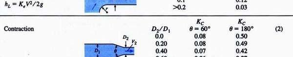
23 Table
24 Note:in The Exansion if the angle is θ you have two choices for the head loss: 1- Use the above equation - Use the abrut exansion equation 4
25 Summary of the Energy equation 1 z 1 1 α1 h z α ht hl γ g γ g Total loss Major loss Minor Loss h L h L, major h L, minor Li i L i j i i j h f K D g g j 5
26 Examle: Liquid flows downward in a 1-cm, vertical, smooth ie with a mean velocity of.0 m/s. The liquid has a density of 1000 kg/m 3 and a viscosity of 0.06 N.s/m. If the ressure at a given section is 600 ka, what will be the ressure at a section 10 m below that section? Solution: ρd Re μ γ 1 α 1 g 0 0 γ g 1 z1 h z α La min ar L 10 f 0.19 h.. m Re L f D g g h t h L ka 6
 flows from the tank shown and through 3/8 inch diameter (ID) tube.")
27 Examle: Kerosene (S0.8 and T68 0 F) flows from the tank shown and through 3/8 inch diameter (ID) tube. Determine the mean velocity in the tube and the discharge. Hint: include the major loss only. 7
28 Solution: assume a laminar flow 3 g 3., γ Ibf/ft, ρ slugs/ft μ Ibf s/ft (Table A. 4 ) 3 L 10 ft, D ft γ 1 g g 1 α1 z1 h α z L h L f D g γ f Re ρd μ ft/s h t Now check Re ( ( ) ρd Re μ 4 10 Q A π ( 1/ 3 ) cfs h L La min ar 8
 for the ie if 3")
29 Examle: Water flows in the ie shown, and the manometer deflects 80 cm. What is the resistance coefficient (friction coefficient) for the ie if 3 m/s? 9
30 Solution: ( ) L t h h z g α γ h z g α γ L 3 4 Eq.(1) g. f g D L f h L M t ti Manometer equation: a ) y ( ). ( S ). y ( w w w γ γ γ Eq.() a From Eq.(1) & () f


31 Examle: A water turbine is connected to a reservoir as shown. The flow rate in this system is 5 cfs. What ower can be delivered by the turbine if its efficiency is 80%? Assume a temerature of 70 0 F. 31
32 Solution: ft/s π ( 1/ 1 ) Re ( ) D ν α z h 1 1 α z ht hl γ g γ g 5 Turbulent Table A.5 at 70 0 F Eq. (1) L hl K e f 0. 5 f g D g 3. 1 / 1 3. Pie entrance at r/d0.0 Shar edge (Table 10.3) Table 10. k s 0. 00" D 1" f Re 6 10 Figure
33 From Eq. (1): W& W& mg & γq W& t W& t mg & γ Q h. ft t h h 550 Ibf.ft/s W h h t η Pum Head fluid γqh wt shaft shaft shaft W shaft Turbine Head W Pum effeciency W W η t γqh Turbine effeciency W t fluid W t Q γ h t η ft.ibf f / s P W t ( h ) horseower 33


34 Examle: Both ies shown have an equivalent sand roughness k s of 0.1 mm and a discharge of o.1 m 3 /s. Also D 1 15 cm, L 1 50 m, D 30 cm, and L 160 m. determine the difference in the watersurface elevation between the two reservoirs. 34
35 Solution: 6 o ν 10 m / T 0 C Q Q. m/s m/s A A30 15 Moody diagram(fig. 10-8): 15D D30 Re Re 4. 4 ν f ν k 0.1 k 0.1 s s D 150 D f γ 0 i 0 0 i o o α i zi h αo zo ht hl g γ g z i 0 z o Δz h L 0 Total loss Major loss Minor Loss h L h L, major h L, minor Li i L i j i i j h f K D g g j 35
36 g g g L D g L D g h L K e K E K E ( f ) 15 ( f ) (ie entrance) at r/d0 ) (Exansion) at D 1 /D 0.0 and θ180 o (by linear interolation) (Exansion) at D 1 /D 0.5 and θ180 o linear interolation: f(x) f(x o ) f(x1 ) x 1 f(x x o o ) (x x o ) f(x 1 ) f(x) f(x 0 ) x o x x 1 36
37 h h m L zi zo Δz hl Alternative Solution for Exansion θ180 o g ( g ) 0 ) g L K e ( f ) 15 ( Two Abrut Exansion m L D g ( f L D g ) 30 h m L Note: for Exansion if θ 180 o you should use the table 37


38 Examle: A tank and iing system is shown. The ie diameter is cm and the total length of ie is 10 m. The two 90 0 elbows are threaded fittings. The vertical distance from the water surface to the ie outlet is 5 m. The velocity of the water in the tank is negligible. Find a) the exit velocity of the water and, b) the height (h) the water jet would rise on exiting the ie. Assume the ie is galvanized iron 38
39 Solution: Assume a turbulent flow: Energy eq. between (1&): h L K e g K b g f 0 1 z hl g L ( K e K b D g (Eq.1) f L D ) g 0.5: Pie entrance at r/d0.0 Shar edge (Table 10.3) 0.9: 90 0 elbow thread (Table 10.3) From Eq.1: 5 ( 1 K e K b 10 f L D ) g Two unknown, usually we assume the friction factor f f To select close I know: k s D 0. 0 Table 10. (galvanized iron) (Eq.) Fig f
40 . 17 m/s from Eq. Now check Re and new f Re D ν (Turbulent ) 3 k s D 0.00 Re With new f D Re ν 10 f Fig m/s from Eq. 4 (Turbulent ) This is close to 4.34 x 10 4 so no further iterations are required 0 0 Energy between and 3 to find h: 3 3 Energy between and 3 to find h: hδz0.4 m γ g z γ g z 3 40
41 Examle: If the um efficiency is 70%, what ower must be sulied to the um in order to um fuel oil (S0.94) at a rate of 1. m 3 /s u to the high reservoir? Assume that the conduit is a steel ie and the viscosity is 5 x 10⁻⁵ m /s. 41
42 γ Solution: 1 Re D ν k s D 0. 6 Table 10. (steel ie) Q m/s A (Turbulent ) Fig f z 1 h α z ht h h z h g γ g α1 L L hl K e K b f ( K e K g g g D g K e K b 0.19: 90 0 smooth bend at r/d1./0.6 (Table 10.3) h z hl 7. 9 m W abrut 190 b 1 0.5: Pie entrance at r/d0.0 Shar edge (Table 10.3) Q γ h η 0. 7 kw η L f L D ) g fluid γqh wt shaft shaft shaft W shaft γqh fluid t W W W ηt W 4
43 10.6: ie Systems When a um is connected to a ieline, it rovides head to the flow. This head sulied by a um is deendant on the flow rate. This imlies that the solution is always straight forward: It is obtained by solving the system equation with the um equation. Every um has its own head s. Discharge curve. 43


44 When the system curve is lotted against the um curve: the intersection oint is the oerating oint at which the system runs. Finding this oint is through a trial and error rocedure. 44
45 45
46 46
47 47
48 48
49 49
50 10.7: Turbulent Flow in Non- Circular Conduits In many engineering alications, non-circular ducts are encountered. Analysis for flow in such ducts is treated in exactly the same manner as in circular ies with the excetion of using the term D h (hydraulic diameter) instead of the diameter. 4AA P: Wetted erimeter D h A: cross-sectional area P Hydraulic radius R h : D h A Rh Dh 4R P 4 Usually it aears in Darcy-Weisbach eqn, relative roughness, Reynolds number h 50
Chapter 7 Energy Principle
 Chater 7: Energy Princile By Dr Ali Jawarneh Hashemite University Outline In this chater we will: Derive and analyse the Energy equation. Analyse the flow and shaft work. Derive the equation for steady
(British) (SI) British Metric L T [V] = L T. [a] = 2 [F] = F = 2 T
![(British) (SI) British Metric L T [V] = L T. [a] = 2 [F] = F = 2 T](/thumbs/77/76088169.jpg "(British) (SI) British Metric L T [V] = L T. [a] = 2 [F] = F = 2 T") Hydraulics ecture # CWR 40 age () ecture # Outline: Review of terminology in fluid mechanics: Energy or work Hydraulic head Bernoulli s aw, Conductivity (examle) ransient & turbulent Friction head loss
Hydraulics ecture # CWR 40 age () ecture # Outline: Review of terminology in fluid mechanics: Energy or work Hydraulic head Bernoulli s aw, Conductivity (examle) ransient & turbulent Friction head loss
FLOW IN CONDUITS. Shear stress distribution across a pipe section. Chapter 10
 Chapter 10 Shear stress distribution across a pipe section FLOW IN CONDUITS For steady, uniform flow, the momentum balance in s for the fluid cylinder yields Fluid Mechanics, Spring Term 2010 Velocity
Chapter 6. Losses due to Fluid Friction
 Chapter 6 Losses due to Fluid Friction 1 Objectives ä To measure the pressure drop in the straight section of smooth, rough, and packed pipes as a function of flow rate. ä To correlate this in terms of
Reynolds, an engineering professor in early 1880 demonstrated two different types of flow through an experiment:
 7 STEADY FLOW IN PIPES 7.1 Reynolds Number Reynolds, an engineering professor in early 1880 demonstrated two different types of flow through an experiment: Laminar flow Turbulent flow Reynolds apparatus
Hydraulics and hydrology
 Hydraulics and hydrology - project exercises - Class 4 and 5 Pipe flow Discharge (Q) (called also as the volume flow rate) is the volume of fluid that passes through an area per unit time. The discharge
Chapter 8: Flow in Pipes
 Objectives 1. Have a deeper understanding of laminar and turbulent flow in pipes and the analysis of fully developed flow 2. Calculate the major and minor losses associated with pipe flow in piping networks
FE Fluids Review March 23, 2012 Steve Burian (Civil & Environmental Engineering)
") Topic: Fluid Properties 1. If 6 m 3 of oil weighs 47 kn, calculate its specific weight, density, and specific gravity. 2. 10.0 L of an incompressible liquid exert a force of 20 N at the earth s surface.
Topic: Fluid Properties 1. If 6 m 3 of oil weighs 47 kn, calculate its specific weight, density, and specific gravity. 2. 10.0 L of an incompressible liquid exert a force of 20 N at the earth s surface.
Chapter 10 Flow in Conduits
 Chapter 10 Flow in Conduits 10.1 Classifying Flow Laminar Flow and Turbulent Flow Laminar flow Unpredictable Turbulent flow Near entrance: undeveloped developing flow In developing flow, the wall shear
Chapter 8: Flow in Pipes
 8-1 Introduction 8-2 Laminar and Turbulent Flows 8-3 The Entrance Region 8-4 Laminar Flow in Pipes 8-5 Turbulent Flow in Pipes 8-6 Fully Developed Pipe Flow 8-7 Minor Losses 8-8 Piping Networks and Pump
Hydraulics. B.E. (Civil), Year/Part: II/II. Tutorial solutions: Pipe flow. Tutorial 1
, Year/Part: II/II. Tutorial solutions: Pipe flow. Tutorial 1") Hydraulics B.E. (Civil), Year/Part: II/II Tutorial solutions: Pipe flow Tutorial 1 -by Dr. K.N. Dulal Laminar flow 1. A pipe 200mm in diameter and 20km long conveys oil of density 900 kg/m 3 and viscosity
Hydraulics B.E. (Civil), Year/Part: II/II Tutorial solutions: Pipe flow Tutorial 1 -by Dr. K.N. Dulal Laminar flow 1. A pipe 200mm in diameter and 20km long conveys oil of density 900 kg/m 3 and viscosity
Mechanical Engineering Programme of Study
 Mechanical Engineering Programme of Study Fluid Mechanics Instructor: Marios M. Fyrillas Email: eng.fm@fit.ac.cy SOLVED EXAMPLES ON VISCOUS FLOW 1. Consider steady, laminar flow between two fixed parallel
1-Reynold s Experiment
 Lect.No.8 2 nd Semester Flow Dynamics in Closed Conduit (Pipe Flow) 1 of 21 The flow in closed conduit ( flow in pipe ) is differ from this occur in open channel where the flow in pipe is at a pressure
Viscous Flow in Ducts
 Dr. M. Siavashi Iran University of Science and Technology Spring 2014 Objectives 1. Have a deeper understanding of laminar and turbulent flow in pipes and the analysis of fully developed flow 2. Calculate
Lesson 6 Review of fundamentals: Fluid flow
 Lesson 6 Review of fundamentals: Fluid flow The specific objective of this lesson is to conduct a brief review of the fundamentals of fluid flow and present: A general equation for conservation of mass
FLUID MECHANICS. Dynamics of Viscous Fluid Flow in Closed Pipe: Darcy-Weisbach equation for flow in pipes. Major and minor losses in pipe lines.
 FLUID MECHANICS Dynamics of iscous Fluid Flow in Closed Pipe: Darcy-Weisbach equation for flow in pipes. Major and minor losses in pipe lines. Dr. Mohsin Siddique Assistant Professor Steady Flow Through
Chapter 5 Mass, Momentum, and Energy Equations
 57:00 Mechanics of Fluids and Transort Processes Chater 5 Professor Fred Stern Fall 006 Chater 5 Mass, Momentum, and Energy Equations Flow Rate and Conservation of Mass. cross-sectional area oriented normal
Chapter 6. Losses due to Fluid Friction
 Chapter 6 Losses due to Fluid Friction 1 Objectives To measure the pressure drop in the straight section of smooth, rough, and packed pipes as a function of flow rate. To correlate this in terms of the
FE Exam Fluids Review October 23, Important Concepts
 FE Exam Fluids Review October 3, 013 mportant Concepts Density, specific volume, specific weight, specific gravity (Water 1000 kg/m^3, Air 1. kg/m^3) Meaning & Symbols? Stress, Pressure, Viscosity; Meaning
Pipe Flow. Lecture 17
 Pipe Flow Lecture 7 Pipe Flow and the Energy Equation For pipe flow, the Bernoulli equation alone is not sufficient. Friction loss along the pipe, and momentum loss through diameter changes and corners
Basic Fluid Mechanics
 Basic Fluid Mechanics Chapter 6A: Internal Incompressible Viscous Flow 4/16/2018 C6A: Internal Incompressible Viscous Flow 1 6.1 Introduction For the present chapter we will limit our study to incompressible
Applied Fluid Mechanics
 Applied Fluid Mechanics 1. The Nature of Fluid and the Study of Fluid Mechanics 2. Viscosity of Fluid 3. Pressure Measurement 4. Forces Due to Static Fluid 5. Buoyancy and Stability 6. Flow of Fluid and
Engineers Edge, LLC PDH & Professional Training
 510 N. Crosslane Rd. Monroe, Georgia 30656 (770) 266-6915 fax (678) 643-1758 Engineers Edge, LLC PDH & Professional Training Copyright, All Rights Reserved Engineers Edge, LLC Pipe Flow-Friction Factor
Chapter 8 Internal Forced Convection
 Chater 8 Internal Forced Convection 8.1 Hydrodynamic Considerations 8.1.1 Flow Conditions may be determined exerimentally, as shown in Figs. 7.1-7.2. Re D ρumd μ where u m is the mean fluid velocity over
Chapter (6) Energy Equation and Its Applications
 Energy Equation and Its Applications") Chapter (6) Energy Equation and Its Applications Bernoulli Equation Bernoulli equation is one of the most useful equations in fluid mechanics and hydraulics. And it s a statement of the principle of conservation
Chapter (6) Energy Equation and Its Applications Bernoulli Equation Bernoulli equation is one of the most useful equations in fluid mechanics and hydraulics. And it s a statement of the principle of conservation
Theory of turbomachinery. Chapter 1
 Theory of turbomachinery Chater Introduction: Basic Princiles Take your choice of those that can best aid your action. (Shakeseare, Coriolanus) Introduction Definition Turbomachinery describes machines
ME 305 Fluid Mechanics I. Part 8 Viscous Flow in Pipes and Ducts. Flow in Pipes and Ducts. Flow in Pipes and Ducts (cont d)
") ME 305 Fluid Mechanics I Flow in Pipes and Ducts Flow in closed conduits (circular pipes and non-circular ducts) are very common. Part 8 Viscous Flow in Pipes and Ducts These presentations are prepared
ME 305 Fluid Mechanics I Flow in Pipes and Ducts Flow in closed conduits (circular pipes and non-circular ducts) are very common. Part 8 Viscous Flow in Pipes and Ducts These presentations are prepared
Bernoulli and Pipe Flow
 Civil Engineering Hydraulics Mechanics of Fluids Head Loss Calculations Bernoulli and The Bernoulli equation that we worked with was a bit simplistic in the way it looked at a fluid system All real systems
V/ t = 0 p/ t = 0 ρ/ t = 0. V/ s = 0 p/ s = 0 ρ/ s = 0
 UNIT III FLOW THROUGH PIPES 1. List the types of fluid flow. Steady and unsteady flow Uniform and non-uniform flow Laminar and Turbulent flow Compressible and incompressible flow Rotational and ir-rotational
Water Circuit Lab. The pressure drop along a straight pipe segment can be calculated using the following set of equations:
 Water Circuit Lab When a fluid flows in a conduit, there is friction between the flowing fluid and the pipe walls. The result of this friction is a net loss of energy in the flowing fluid. The fluid pressure
PIPING SYSTEMS. Pipe and Tubing Standards Sizes for pipes and tubes are standardized. Pipes are specified by a nominal diameter and a schedule number.
 PIPING SYSTEMS In this chapter we will review some of the basic concepts associated with piping systems. Topics that will be considered in this chapter are - Pipe and tubing standards - Effective and hydraulic
Hydraulics for Urban Storm Drainage
 Urban Hydraulics Hydraulics for Urban Storm Drainage Learning objectives: understanding of basic concepts of fluid flow and how to analyze conduit flows, free surface flows. to analyze, hydrostatic pressure
Chapter 3 Water Flow in Pipes
 The Islamic University o Gaza Faculty o Engineering Civil Engineering Department Hydraulics - ECI 33 Chapter 3 Water Flow in Pipes 3. Description o A Pipe Flow Water pipes in our homes and the distribution
Piping Systems and Flow Analysis (Chapter 3)
") Piping Systems and Flow Analysis (Chapter 3) 2 Learning Outcomes (Chapter 3) Losses in Piping Systems Major losses Minor losses Pipe Networks Pipes in series Pipes in parallel Manifolds and Distribution
Piping Systems and Flow Analysis (Chapter 3) 2 Learning Outcomes (Chapter 3) Losses in Piping Systems Major losses Minor losses Pipe Networks Pipes in series Pipes in parallel Manifolds and Distribution
Pipe Flow/Friction Factor Calculations using Excel Spreadsheets
 Pipe Flow/Friction Factor Calculations using Excel Spreadsheets Harlan H. Bengtson, PE, PhD Emeritus Professor of Civil Engineering Southern Illinois University Edwardsville Table of Contents Introduction
Optimisation of Pressure Loss and Flow Distribution at Pipe Bifurcation
 ISSN 9 86 Volume, Issue 9 Setember 07 Otimisation of Pressure Loss and Flow Distribution at Pie Bifurcation Dr. Nagaraj Sitaram Professor, Deartment of Civil Engineering,School of Engineering Technology,
STEADY FLOW THROUGH PIPES DARCY WEISBACH EQUATION FOR FLOW IN PIPES. HAZEN WILLIAM S FORMULA, LOSSES IN PIPELINES, HYDRAULIC GRADE LINES AND ENERGY
 STEADY FLOW THROUGH PIPES DARCY WEISBACH EQUATION FOR FLOW IN PIPES. HAZEN WILLIAM S FORMULA, LOSSES IN PIPELINES, HYDRAULIC GRADE LINES AND ENERGY LINES 1 SIGNIFICANCE OF CONDUITS In considering the convenience
FACULTY OF CHEMICAL & ENERGY ENGINEERING FLUID MECHANICS LABORATORY TITLE OF EXPERIMENT: MINOR LOSSES IN PIPE (E4)
") FACULTY OF CHEMICAL & ENERGY ENGINEERING FLUID MECHANICS LABORATORY TITLE OF EXPERIMENT: MINOR LOSSES IN PIPE (E4) 1 1.0 Objectives The objective of this experiment is to calculate loss coefficient (K
FACULTY OF CHEMICAL & ENERGY ENGINEERING FLUID MECHANICS LABORATORY TITLE OF EXPERIMENT: MINOR LOSSES IN PIPE (E4) 1 1.0 Objectives The objective of this experiment is to calculate loss coefficient (K
Atmospheric pressure. 9 ft. 6 ft
 Name CEE 4 Final Exam, Aut 00; Answer all questions; 145 points total. Some information that might be helpful is provided below. A Moody diagram is printed on the last page. For water at 0 o C (68 o F):
Chapter 7 The Energy Equation
 Chapter 7 The Energy Equation 7.1 Energy, Work, and Power When matter has energy, the matter can be used to do work. A fluid can have several forms of energy. For example a fluid jet has kinetic energy,
2 Internal Fluid Flow
 Internal Fluid Flow.1 Definitions Fluid Dynamics The study of fluids in motion. Static Pressure The pressure at a given point exerted by the static head of the fluid present directly above that point.
Real Flows (continued)
") al Flows (continued) So ar we have talked about internal lows ideal lows (Poiseuille low in a tube) real lows (turbulent low in a tube) Strategy or handling real lows: How did we arrive at correlations?
al Flows (continued) So ar we have talked about internal lows ideal lows (Poiseuille low in a tube) real lows (turbulent low in a tube) Strategy or handling real lows: How did we arrive at correlations?
Review of pipe flow: Friction & Minor Losses
 ENVE 204 Lecture -1 Review of pipe flow: Friction & Minor Losses Assist. Prof. Neslihan SEMERCİ Marmara University Department of Environmental Engineering Important Definitions Pressure Pipe Flow: Refers
a) Derive general expressions for the stream function Ψ and the velocity potential function φ for the combined flow. [12 Marks]
![a) Derive general expressions for the stream function Ψ and the velocity potential function φ for the combined flow. [12 Marks]](/thumbs/87/95430472.jpg "a) Derive general expressions for the stream function Ψ and the velocity potential function φ for the combined flow. [12 Marks]") Question 1 A horizontal irrotational flow system results from the combination of a free vortex, rotating anticlockwise, of strength K=πv θ r, located with its centre at the origin, with a uniform flow
Question 1 A horizontal irrotational flow system results from the combination of a free vortex, rotating anticlockwise, of strength K=πv θ r, located with its centre at the origin, with a uniform flow
Uniform Channel Flow Basic Concepts. Definition of Uniform Flow
 Uniform Channel Flow Basic Concepts Hydromechanics VVR090 Uniform occurs when: Definition of Uniform Flow 1. The depth, flow area, and velocity at every cross section is constant 2. The energy grade line,
When water (fluid) flows in a pipe, for example from point A to point B, pressure drop will occur due to the energy losses (major and minor losses).
 flows in a pipe, for example from point A to point B, pressure drop will occur due to the energy losses (major and minor losses).") PRESSURE DROP AND OSSES IN PIPE When water (luid) lows in a pipe, or example rom point A to point B, pressure drop will occur due to the energy losses (major and minor losses). A B Bernoulli equation:
PRESSURE DROP AND OSSES IN PIPE When water (luid) lows in a pipe, or example rom point A to point B, pressure drop will occur due to the energy losses (major and minor losses). A B Bernoulli equation:
F L U I D S Y S T E M D Y N A M I C S
 F L U I D S Y S T E M D Y N A M I C S T he proper design, construction, operation, and maintenance of fluid systems requires understanding of the principles which govern them. These principles include
Determination of Pressure Losses in Hydraulic Pipeline Systems by Considering Temperature and Pressure
 Paer received: 7.10.008 UDC 61.64 Paer acceted: 0.04.009 Determination of Pressure Losses in Hydraulic Pieline Systems by Considering Temerature and Pressure Vladimir Savi 1,* - Darko Kneževi - Darko Lovrec
FLUID MECHANICS D203 SAE SOLUTIONS TUTORIAL 2 APPLICATIONS OF BERNOULLI SELF ASSESSMENT EXERCISE 1
 FLUID MECHANICS D203 SAE SOLUTIONS TUTORIAL 2 APPLICATIONS OF BERNOULLI SELF ASSESSMENT EXERCISE 1 1. A pipe 100 mm bore diameter carries oil of density 900 kg/m3 at a rate of 4 kg/s. The pipe reduces
CVE 372 HYDROMECHANICS EXERCISE PROBLEMS
 VE 37 HYDROMEHNIS EXERISE PROLEMS 1. pump that has the characteristic curve shown in the accompanying graph is to be installed in the system shown. What will be the discharge of water in the system? Take
ME 305 Fluid Mechanics I. Chapter 8 Viscous Flow in Pipes and Ducts
 ME 305 Fluid Mechanics I Chapter 8 Viscous Flow in Pipes and Ducts These presentations are prepared by Dr. Cüneyt Sert Department of Mechanical Engineering Middle East Technical University Ankara, Turkey
ACCOUNTING FOR FRICTION IN THE BERNOULLI EQUATION FOR FLOW THROUGH PIPES
 ACCOUNTING FOR FRICTION IN THE BERNOULLI EQUATION FOR FLOW THROUGH PIPES Some background information first: We have seen that a major limitation of the Bernoulli equation is that it does not account for
Only if handing in. Name: Student No.: Page 2 of 7
 UNIVERSITY OF TORONTO FACULTY OF APPLIED SCIENCE AND ENGINEERING FINAL EXAMINATION, DECEMBER 10, 2014 2:00 PM 2.5 HOURS CHE 211F FLUID MECHANICS EXAMINER: PROFESSOR D.G. ALLEN ANSWER ALL SEVEN (7) QUESTIONS
Useful concepts associated with the Bernoulli equation. Dynamic
 Useful concets associated with the Bernoulli equation - Static, Stagnation, and Dynamic Pressures Bernoulli eq. along a streamline + ρ v + γ z = constant (Unit of Pressure Static (Thermodynamic Dynamic
Major and Minor Losses
 Abstract Major and Minor Losses Caitlyn Collazo, Team 2 (1:00 pm) A Technovate fluid circuit system was used to determine the pressure drop across a pipe section and across an orifice. These pressure drops
Applied Fluid Mechanics
 Applied Fluid Mechanics 1. The Nature of Fluid and the Study of Fluid Mechanics 2. Viscosity of Fluid 3. Pressure Measurement 4. Forces Due to Static Fluid 5. Buoyancy and Stability 6. Flow of Fluid and
Lesson 37 Transmission Of Air In Air Conditioning Ducts
 Lesson 37 Transmission Of Air In Air Conditioning Ducts Version 1 ME, IIT Kharagpur 1 The specific objectives of this chapter are to: 1. Describe an Air Handling Unit (AHU) and its functions (Section 37.1).
vector H. If O is the point about which moments are desired, the angular moment about O is given:
 The angular momentum A control volume analysis can be applied to the angular momentum, by letting B equal to angularmomentum vector H. If O is the point about which moments are desired, the angular moment
OE4625 Dredge Pumps and Slurry Transport. Vaclav Matousek October 13, 2004
 OE465 Vaclav Matousek October 13, 004 1 Dredge Vermelding Pumps onderdeel and Slurry organisatie Transport OE465 Vaclav Matousek October 13, 004 Dredge Vermelding Pumps onderdeel and Slurry organisatie
PIPE FLOW. The Energy Equation. The first law of thermodynamics for a system is, in words = +
 The Energy Equation PIPE FLOW The first law of thermodynamics for a system is, in words Time rate of increase of the total storage energy of the t Net time rate of energy addition by heat transfer into
Fluid Mechanics Answer Key of Objective & Conventional Questions
 019 MPROVEMENT Mechanical Engineering Fluid Mechanics Answer Key of Objective & Conventional Questions 1 Fluid Properties 1. (c). (b) 3. (c) 4. (576) 5. (3.61)(3.50 to 3.75) 6. (0.058)(0.05 to 0.06) 7.
Friction Factors and Drag Coefficients
 Levicky 1 Friction Factors and Drag Coefficients Several equations that we have seen have included terms to represent dissipation of energy due to the viscous nature of fluid flow. For example, in the
ρg 998(9.81) LV 50 V. d2g 0.062(9.81)
 LV 50 V. d2g 0.062(9.81)") 6.78 In Fig. P6.78 the connecting pipe is commercial steel 6 cm in diameter. Estimate the flow rate, in m 3 /h, if the fluid is water at 0 C. Which way is the flow? Solution: For water, take ρ = 998 kg/m
6.78 In Fig. P6.78 the connecting pipe is commercial steel 6 cm in diameter. Estimate the flow rate, in m 3 /h, if the fluid is water at 0 C. Which way is the flow? Solution: For water, take ρ = 998 kg/m
Chapter 8 Flow in Conduits
 57:00 Mechanics of Fluids and Transport Processes Chapter 8 Professor Fred Stern Fall 013 1 Chapter 8 Flow in Conduits Entrance and developed flows Le = f(d, V,, ) i theorem Le/D = f(re) Laminar flow:
UNIT II Real fluids. FMM / KRG / MECH / NPRCET Page 78. Laminar and turbulent flow
 UNIT II Real fluids The flow of real fluids exhibits viscous effect that is they tend to "stick" to solid surfaces and have stresses within their body. You might remember from earlier in the course Newtons
Fluid Mechanics c) Orificemeter a) Viscous force, Turbulence force, Compressible force a) Turbulence force c) Integration d) The flow is rotational
 Orificemeter a) Viscous force, Turbulence force, Compressible force a) Turbulence force c) Integration d) The flow is rotational") Fluid Mechanics 1. Which is the cheapest device for measuring flow / discharge rate. a) Venturimeter b) Pitot tube c) Orificemeter d) None of the mentioned 2. Which forces are neglected to obtain Euler
Fluid Mechanics 1. Which is the cheapest device for measuring flow / discharge rate. a) Venturimeter b) Pitot tube c) Orificemeter d) None of the mentioned 2. Which forces are neglected to obtain Euler
Fluid Mechanics II 3 credit hour. Fluid flow through pipes-minor losses
 COURSE NUMBER: ME 323 Fluid Mechanics II 3 credit hour Fluid flow through pipes-minor losses Course teacher Dr. M. Mahbubur Razzaque Professor Department of Mechanical Engineering BUET 1 Losses in Noncircular
Measurement of cyclone separator
 Measurement of cyclone searator. Aim of the measurement Cyclones are widely used in industry (in food and chemical industry, in energy technology and in buildings) to remove dust and other articles from
2, where dp is the constant, R is the radius of
 Dynamics of Viscous Flows (Lectures 8 to ) Q. Choose the correct answer (i) The average velocity of a one-dimensional incompressible fully developed viscous flow between two fixed parallel plates is m/s.
SKM DRILLING ENGINEERING. Chapter 3 - Drilling Hydraulics
 1 SKM 3413 - DRILLING ENGINEERING Chapter 3 - Drilling Hydraulics Assoc. Prof. Abdul Razak Ismail Petroleum Engineering Dept. Faculty of Petroleum & Renewable Energy Eng. Universiti Teknologi Malaysia
M E 320 Professor John M. Cimbala Lecture 24
 M E 30 Professor John M. Cimbala Lecture 4 Today, we will: Discuss pump performance curves Discuss how to match a pump and a piping system, and do some example problems. Pump Performance a. Pump performance
FLOW FRICTION CHARACTERISTICS OF CONCRETE PRESSURE PIPE
 11 ACPPA TECHNICAL SERIES FLOW FRICTION CHARACTERISTICS OF CONCRETE PRESSURE PIPE This paper presents formulas to assist in hydraulic design of concrete pressure pipe. There are many formulas to calculate
HEAT TRANSFER BY CONVECTION. Dr. Şaziye Balku 1
 HEAT TRANSFER BY CONVECTION Dr. Şaziye Balku 1 CONDUCTION Mechanism of heat transfer through a solid or fluid in the absence any fluid motion. CONVECTION Mechanism of heat transfer through a fluid in the
Chapter Four Hydraulic Machines
 Contents 1- Introduction. - Pumps. Chapter Four Hydraulic Machines (لفرع الميكانيك العام فقط ( Turbines. -3 4- Cavitation in hydraulic machines. 5- Examples. 6- Problems; sheet No. 4 (Pumps) 7- Problems;
PROPERTIES OF FLUIDS
 Unit - I Chapter - PROPERTIES OF FLUIDS Solutions of Examples for Practice Example.9 : Given data : u = y y, = 8 Poise = 0.8 Pa-s To find : Shear stress. Step - : Calculate the shear stress at various
Compressible Duct Flow with Friction
 Compressible Duct Flow with Friction We treat only the effect of friction, neglecting area change and heat transfer. The basic assumptions are 1. Steady one-dimensional adiabatic flow 2. Perfect gas with
 CE 6303 MECHANICS OF FLUIDS L T P C QUESTION BANK 3 0 0 3 UNIT I FLUID PROPERTIES AND FLUID STATICS PART - A 1. Define fluid and fluid mechanics. 2. Define real and ideal fluids. 3. Define mass density
CHAPTER 3 BASIC EQUATIONS IN FLUID MECHANICS NOOR ALIZA AHMAD
 CHAPTER 3 BASIC EQUATIONS IN FLUID MECHANICS 1 INTRODUCTION Flow often referred as an ideal fluid. We presume that such a fluid has no viscosity. However, this is an idealized situation that does not exist.
Chapter (3) Water Flow in Pipes
 Water Flow in Pipes") Chapter (3) Water Flow in Pipes Water Flow in Pipes Bernoulli Equation Recall fluid mechanics course, the Bernoulli equation is: P 1 ρg + v 1 g + z 1 = P ρg + v g + z h P + h T + h L Here, we want to study
Chapter (3) Water Flow in Pipes Water Flow in Pipes Bernoulli Equation Recall fluid mechanics course, the Bernoulli equation is: P 1 ρg + v 1 g + z 1 = P ρg + v g + z h P + h T + h L Here, we want to study
LECTURE 6- ENERGY LOSSES IN HYDRAULIC SYSTEMS SELF EVALUATION QUESTIONS AND ANSWERS
 LECTURE 6- ENERGY LOSSES IN HYDRAULIC SYSTEMS SELF EVALUATION QUESTIONS AND ANSWERS 1. What is the head loss ( in units of bars) across a 30mm wide open gate valve when oil ( SG=0.9) flow through at a
S.E. (Mech.) (First Sem.) EXAMINATION, (Common to Mech/Sandwich) FLUID MECHANICS (2008 PATTERN) Time : Three Hours Maximum Marks : 100
 (First Sem.) EXAMINATION, (Common to Mech/Sandwich) FLUID MECHANICS (2008 PATTERN) Time : Three Hours Maximum Marks : 100") Total No. of Questions 12] [Total No. of Printed Pages 8 Seat No. [4262]-113 S.E. (Mech.) (First Sem.) EXAMINATION, 2012 (Common to Mech/Sandwich) FLUID MECHANICS (2008 PATTERN) Time : Three Hours Maximum
Total No. of Questions 12] [Total No. of Printed Pages 8 Seat No. [4262]-113 S.E. (Mech.) (First Sem.) EXAMINATION, 2012 (Common to Mech/Sandwich) FLUID MECHANICS (2008 PATTERN) Time : Three Hours Maximum
Chapter 4 DYNAMICS OF FLUID FLOW
 Faculty Of Engineering at Shobra nd Year Civil - 016 Chapter 4 DYNAMICS OF FLUID FLOW 4-1 Types of Energy 4- Euler s Equation 4-3 Bernoulli s Equation 4-4 Total Energy Line (TEL) and Hydraulic Grade Line
INSTRUCTIONS FOR LABORATORY EXPERIMENT IN FLUID MECHANICS
 INSTRUCTIONS FOR LABORATORY EXPERIMENT IN FLUID MECHANICS VT2010 Pipe Flow: General Information: Attendance at the laboratory experiment is required for completion of the course. The experiments will be
R09. d water surface. Prove that the depth of pressure is equal to p +.
 Code No:A109210105 R09 SET-1 B.Tech II Year - I Semester Examinations, December 2011 FLUID MECHANICS (CIVIL ENGINEERING) Time: 3 hours Max. Marks: 75 Answer any five questions All questions carry equal
INSTITUTE OF AERONAUTICAL ENGINEERING Dundigal, Hyderabad AERONAUTICAL ENGINEERING QUESTION BANK : AERONAUTICAL ENGINEERING.
 Course Name Course Code Class Branch INSTITUTE OF AERONAUTICAL ENGINEERING Dundigal, Hyderabad - 00 0 AERONAUTICAL ENGINEERING : Mechanics of Fluids : A00 : II-I- B. Tech Year : 0 0 Course Coordinator
FRICTION LOSS ALONG A PIPE
 FRICTION LOSS ALONG A PIPE 1. INTRODUCTION The frictional resistance to which fluid is subjected as it flows along a pipe results in a continuous loss of energy or total head of the fluid. Fig 1 illustrates
Dimensions represent classes of units we use to describe a physical quantity. Most fluid problems involve four primary dimensions
 BEE 5330 Fluids FE Review, Feb 24, 2010 1 A fluid is a substance that can not support a shear stress. Liquids differ from gasses in that liquids that do not completely fill a container will form a free
A Model Answer for. Problem Set #4 FLUID DYNAMICS
 A Model Answer for Problem Set #4 FLUID DYNAMICS Problem. Some elocity measurements in a threedimensional incomressible flow field indicate that u = 6xy and = -4y z. There is some conflicting data for
Sourabh V. Apte. 308 Rogers Hall
 Sourabh V. Apte 308 Rogers Hall sva@engr.orst.edu 1 Topics Quick overview of Fluid properties, units Hydrostatic forces Conservation laws (mass, momentum, energy) Flow through pipes (friction loss, Moody
Liquid or gas flow through pipes or ducts is commonly used in heating and
 cen58933_ch08.qxd 9/4/2002 11:29 AM Page 419 INTERNAL FORCED CONVECTION CHAPTER 8 Liquid or gas flow through pipes or ducts is commonly used in heating and cooling applications. The fluid in such applications
PIPE FLOWS: LECTURE /04/2017. Yesterday, for the example problem Δp = f(v, ρ, μ, L, D) We came up with the non dimensional relation
 We came up with the non dimensional relation") /04/07 ECTURE 4 PIPE FOWS: Yesterday, for the example problem Δp = f(v, ρ, μ,, ) We came up with the non dimensional relation f (, ) 3 V or, p f(, ) You can plot π versus π with π 3 as a parameter. Or,
/04/07 ECTURE 4 PIPE FOWS: Yesterday, for the example problem Δp = f(v, ρ, μ,, ) We came up with the non dimensional relation f (, ) 3 V or, p f(, ) You can plot π versus π with π 3 as a parameter. Or,
Lecture 30 Review of Fluid Flow and Heat Transfer
 Objectives In this lecture you will learn the following We shall summarise the principles used in fluid mechanics and heat transfer. It is assumed that the student has already been exposed to courses in
Solved problems 4 th exercise
 Soled roblem th exercie Soled roblem.. On a circular conduit there are different diameter: diameter D = m change into D = m. The elocity in the entrance rofile wa meaured: = m -. Calculate the dicharge
Experiment- To determine the coefficient of impact for vanes. Experiment To determine the coefficient of discharge of an orifice meter.
 SUBJECT: FLUID MECHANICS VIVA QUESTIONS (M.E 4 th SEM) Experiment- To determine the coefficient of impact for vanes. Q1. Explain impulse momentum principal. Ans1. Momentum equation is based on Newton s
EXPERIMENT No.1 FLOW MEASUREMENT BY ORIFICEMETER
 EXPERIMENT No.1 FLOW MEASUREMENT BY ORIFICEMETER 1.1 AIM: To determine the co-efficient of discharge of the orifice meter 1.2 EQUIPMENTS REQUIRED: Orifice meter test rig, Stopwatch 1.3 PREPARATION 1.3.1
Chapter (3) Water Flow in Pipes
 Water Flow in Pipes") Chapter (3) Water Flow in Pipes Water Flow in Pipes Bernoulli Equation Recall fluid mechanics course, the Bernoulli equation is: P 1 ρg + v 1 g + z 1 = P ρg + v g + z h P + h T + h L Here, we want to study
Chapter (3) Water Flow in Pipes Water Flow in Pipes Bernoulli Equation Recall fluid mechanics course, the Bernoulli equation is: P 1 ρg + v 1 g + z 1 = P ρg + v g + z h P + h T + h L Here, we want to study
Comparison of Maximum Allowable Pump Speed in a Horizontal and Vertical Pipe of Equal Geometry at Constant Power
 Pak. J. Engg. & Al. Sci. Vol. 16, Jan., 015 (. 110 10) Comarison of Maximum Allowable Pum Seed in a Horizontal and Vertical Pie of Equal Geometry at Constant Power D. Bashar 1, A. Usman, M. K. Aliyu 3
ME 309 Fluid Mechanics Fall 2010 Exam 2 1A. 1B.
 Fall 010 Exam 1A. 1B. Fall 010 Exam 1C. Water is flowing through a 180º bend. The inner and outer radii of the bend are 0.75 and 1.5 m, respectively. The velocity profile is approximated as C/r where C
CIVE HYDRAULIC ENGINEERING PART II Pierre Julien Colorado State University
 1 CIVE 401 - HYDRAULIC ENGINEERING PART II Pierre Julien Colorado State University Problems with and are considered moderate and those with are the longest and most difficult. In 2018 solve the problems
FLUID MECHANICS PROF. DR. METİN GÜNER COMPILER
 FLUID MECHANICS PROF. DR. METİN GÜNER COMPILER ANKARA UNIVERSITY FACULTY OF AGRICULTURE DEPARTMENT OF AGRICULTURAL MACHINERY AND TECHNOLOGIES ENGINEERING 1 5. FLOW IN PIPES 5.1.3. Pressure and Shear Stress