An investigation of a compact heat exchanger unit using CFD with experimental support
|
|
|
- Rudolf Sutton
- 5 years ago
- Views:
Transcription


1 EPJ Web of Conferences 92, (2015) DOI: /epjconf/ C Owned by the authors, published by EDP Sciences, 2015 An investigation of a compact heat exchanger unit using CFD with experimental support Pavel Peukert1,a, Jan Kola r 1,b, and Karel Ada mek1,c 1 VU TS a. s., Sva rovska 619, Liberec, Czech Republic Abstract. The paper contains a comparison of a numerical simulation with a real experiment. In the measured and simulated device is located a heat exchanger with a centrifugal fan. Due to the fan and the geometrical arrangement the flow is relative uneven and so the heat transfer hard to predict. The simulation should be time and cost affordable, so a standard k- turbulence model and a relative simple mesh was used for the computations. 1 Introduction Numerical simulations represent today a common method for to support the design process of new products. The decision to use such methods varies from cost and time saving to basic flow investigation in local areas where the experimental approach is often not possible. The numerical simulations should go hand in hand with experimental validation, because the computations are given by a simplified mathematical description of a real physical system. The simplification of the system description is necessary for a time relevant computation with an affordable computation equipment. For common engineering tasks the DNS (Direct Numerical Simulation) is unusable so still the RANS (Reynolds-averaged Navier-Stokes equations) based turbulence models represents the main group. Especially the two equation models are popular. Often the various k- and k-ω models are usable for a lot of common tasks. A detailed explanation of the problematic could be find in [1] or [2]. This paper introduces a numerical flow simulation with heat transfer which was validated with experimental data. The main part is a heat exchanger with an uneven inlet profile, from the point of flow direction and velocity size. Because of the design complexity a high element count had to be used, but the detail resolution partially depend on the used computer performance so a balanced element size setting, modeling parameters had to be chosen. The experimental part should confirm proper model selection and settings sufficiently. 1.1 Experimental device For experimental purposes was prepared a unit which is shown in 1. The case holds all internal parts and defines the air flow path. At unit the bottom is located a centrifugal fan, which sucks the air from the surroundings and transport the air to the heat exchanger. The air is heated up and exits the unit via an air grill, which gives the stream a certain direction. a b c pavel.peukert@vuts.cz jan.kolar@vuts.cz karel.adamek@vuts.cz Figure 1. measured experimental unit. The fan is a usual commercial one with few speed stages and a plastic impeller. The heat exchanger could be classed as a compact cross flow tube-fin gas-liquid heat exchanger [3]. It consists from copper tubes and about 150 aluminum fins. A scheme of the side view is shown in 2, with the water path and numbered tube passages. It is suggested that incoming air enters the heat exchanger under an angle, which is variable at different points of the surface. So the tube layout for the flow is mainly considered to be staggered. The air grill is a simple grating with a modified outlet for the control of the outlet stream direction. 2 Experiment description To get appropriate data for the validation of numerical simulations, two experimental parts were done. One consists of the velocity measurements of non heated air stream from the air grill and the second measures the heat transfer rates and temperature distribution of the experimental unit. The experiments were done at different fan speed levels, and water temperature inlets and flow rates. 2.1 Velocity profile The measurements of the outlet velocity profile were done with hot wire anemometry. The hot wire probe was traversed automatic in a predefined grid in a specified height over the air grill. A simplified layout of the measurement is! Article available at or


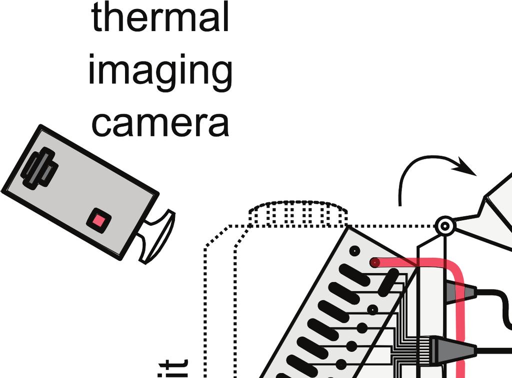


2 EPJ Web of Conferences Figure 4. Experimental layout for heat transfer measurement. 2.2 Heat transfer rates and temperature distribution on the heat heat exchanger surface Figure 2. Heat exchanger description. Figure 3. Measurement of the velocity profile at specified height above the air grill. shown in 3. The position and velocity data were collected to a computer for later evaluation. The measurements were performed in an empty and closed room to ensure minimal disturbances. To have an adequate compartment, the measurements were taken for all three speed levels of the fan. With respect to probe (wire) dimensions was chosen a grid which places the measurement points of one column in the center of the slit passage, totally seven and two points outside of it. In the longitudinal direction were equally placed 33 points, where again the side point were not above the slots. The measurements were done in two planes above the air grill, the first at a height of 10 mm and the second at 100 mm from the highest point of the air grill. The measurement was performed in an empty room with relative steady climatic conditions. The experimental layout is shown in 4. The measured unit was prepared to provide the ability of fast lid removing to observe the temperature field on the heat exchanger with a thermal imaging camera. The heat exchanger was connected to a heat source via hoses. At the heat exchanger connections were special widgets with thermocouples for bulk temperature measurements to get the total water temperature gradient trough the heat exchanger. On one of the hoses was installed a flow meter to get the water flow rate. On every knee, which connects two tubes was installed a thermocouple, like it is shown in figure 5. A very slight layer of thermal grease was applied between the thermocouple and the copper surface to minimize thermal resistance. An expected measurement error for calibrated thermocouples could be expected up to 0.2 C. The data from the thermocouples were collected via a data acquisition unit on a flash disk for later evaluation. So it was possible to get the temperature drop on every tube, but due to uneven air flow profile trough the heat exchanger it was appropriate to get an idea about the distribution along tubes. For that reason was used the thermal imaging camera. A little problematic is to ensure to determine the right emissivity of the aluminum fins so a calibration measurement was done. The heat exchanger was placed in a climatic chamber. The temperature in the chamber was set to few temperatures, which ranged about the expected values and an averaged emissivity was calculated. The whole measurement takes place in following way. The fan of the measured unit was set to a given level. A demanded water temperature was set to the inlet of the heat exchanger and the flow rate was changed until a required temperature drop between the inlet and outlet achieved. After the whole system was stabilized, the water flow rate, temperature on the inlet, outlet and individual knees was measured. Then one of the technicians opened fast the removable lid of the unit, while another take fast a picture of the actual temperature field of the heat exchanger. Then the whole process could start for another temperature p.2


3 EFM 2014 Figure 5. Heat exchanger knee with thermocouple. Figure 7. Computational mesh. Figure 6. Geometrical model. 3 Numerical simulations The preprocesing numerical simulation was done with the comercial software package Ansys Fluent. 3.1 Model and Mesh The model of the measured unit was simplified, to substantial details, which noticeable effect the flow. In figure 6 is shown, the geometrical model. It consists from few zones, the centrifugal fan, the inner part of the unit, the heat exchanger, the air grill and the surroundings. The model was meshed via Ansys Meshing and counts more than 10.5 million elements, a part of it is shown in figure 7. It is clear that the mesh and model was done with respect to a reasonable computation time. For example it was made a concession to the mesh size although a more detailed mesh were desired in the upper part with the unstructured tetrahedron zone in figure 7, because here lies the second cross section where the velocity profile was measured. The heat exchanger is the most complex part of the model. It takes about 6.5 million elements. The heat transfer was modeled directly from the heating water to the cold air. The heat exchanger model is relative detailed. It includes all tubes and fins. To ensure a good simulation of the heat transfer the mesh of the first fin was swept over the entire heat exchanger in the tube axis direction. The mesh in the air gaps between the fins is formed with a maximum grow rate factor of 1.2 so that in the middle is located the highest element and at the surface region were the smallest ones to allow a proper computation of the boundary layer effect. In the normal direction to the tube axis is the mesh relative coarse, but detailed enough due to the flow character despite the higher aspect ratio of the elements. The centrifugal fan part is also relative complex. The geometry of the impeller blades is based on a contour scan of the impler where the geometry was measured. The fan model is divided in to three zones. The inner stationary zone, the moving reference frame zone, and the remaining fan housing zone. Inner zones of the unit, copy coarsely the original geometry, such detail as small scree holes, small chamfers were omitted. The geometry of the air grill is designed like the original, with radiuses and gaps. The surroundings is few meters around the unit to ensure no affecting of the flow character in and a certain area around the unit p.3


. Figure 9. Computed velocity profile in height level 10 mm (m/s).")

4 EPJ Web of Conferences 3.2 Computations For processing of was used Ansys Fluent. Because the flow is over most zones turbulent, the standard k-epsilon model was used. The task was defined as a steady problem. To initiate the flow, the motion reference frame was set to the same impeller speed like it was determined in the experiment. The pressure inlet on the centrifugal fan was set with zero overpressure, like the pressure outlets on the surroundings boarder. The temperature of the incoming water to the heat exchanger was set to the measured temperature in the experiment and the mass flow rate also. Material properties were set corresponding to the real used materials or similar. The air was assumed like incompressible, with constant properties and density, which is acceptable due to the flow and temperature range. The task was initialized and run for few thousand iterations, until the energy residuals stagnate. The mass flow and energy balance was checked. Figure 8. Measured velocity profile in height level 10 mm (m/s). Figure 9. Computed velocity profile in height level 10 mm (m/s). 4 Data evaluation The obtained data from the experiment and numerical simulations were brought together, evaluated and compared. Because of the large amount of data sets only a one representative set result will be shown. Some of the comparison sets which show colored contours don t use the same color scheme, because different software was used for evaluation (for the experimental part Wolfram Mathematica and for numerical Ansys Fluent). For all measurements and simulations were tested 3 regimes of different fan speed levels and different temperature drops. Because these tests result in a large output set, only the second set on the middle fan speed level is presented. It should be mentioned, that that case represents the worst in the comparison between computation and measured values. Figure 10. Measured velocity profile in height level 100 mm (m/s). Figure 11. Measured velocity profile in height level 100 mm (m/s). 4.1 Velocity profile comparison For the comparison of the velocity profile outlet of the unit was chosen to show the case with the third fan speed level. In figures 8 and 9 were shown the results of the measured and computed velocity profile 10 mm over the air grill. The pictures don t look direct the same, because the picture of the experiment had a significantly smaller resolution and averages over a larger area, the experimental data were interpolated for smoother transitions. But both figures had the same tendencies and similar velocities at the given points. So in 8 and 9 is the same profiles. The velocity decrease from the sides to the middle at the bottom part of the figure. And the highest velocities at the top. The velocity peaks from the measurement were about 2.8 m/s and from the simulation about 2.7 m/s, which is comparable. If the figure 10 and 11 is shown a cross section in the height of 100 mm. If they were compared the tendency is relative similar, also something like the two bumps, could be observed in 10 but in the experiment holds the stream a more compact shape. That could be given due to the bigger elements, which grow fast behind the air grill. That could be seen in 7. In the observed cross section, the elements had sizes comparable with the air grill gap, but it should not influent the desired phenomenon. But if the velocities at that cross section were the main observed theme, the mesh should be refined. The velocity peaks here were about 2.5 m/s for the experiment in three points, but most of the time is the upper corner at velocities about 2.2 m/s. In the simulation the peaks at the upper corner is about 2.1 m/s, which quite similar. For the not shown results the comparison was similar, and should be mentioned as satisfying. 4.2 Temperature profiles on the heat exchanger To verify the heat transfer part of the simulation was chosen to observe the temperature distribution over the heat exchanger. In figure 13 is shown the picture taken by the thermal imaging camera (the lighter part are warmer than the dark ones), where the temperature across the drawn lines is depicted in figure 14. In comparison with figure 15 is the temperature measured via the camera lower about 5 C, but the temperature pater is near the same, what supports the numerical results. To measure the temperature is relative complicated, especially for material like aluminum and if one presumes to look in to the gaps between the fins p.4


5 EFM 2014 Figure 12. Computed heat exchanger temperatures. Figure 15. Chart of heat exchanger knees and in/outlet. Figure 16. Cross counter flow arrangement. Figure 13. Heat exchanger image taken by thermal imaging camera. Figure 14. Temperature for given lines in figure 13. plain, because some tubes are arranged near cross parallel flow due to the air flow, like it is show in figure 16. So that the warmer water is significantly cooled down by the incoming cold air and the air is heat up. For the second tube is the temperature difference between the air and water significantly smaller, so that the water temperature drop is relative small compared to the first tube. This case corresponds to the knee pairs 4-5, 8-9, A little strange looks the pair 14-15, which has a relative high temperature drop, and between is the decrease low. If the simulation is compared to the measurement, so there is often (excluded point 20 and 21) a similar tendency, but the heat transfer rate is clearly over predicted by the numerical part. But the desired value is the heat transfer rate, which is computed by equation 1, where m represents the water flow, cp the specific water heat capacity and Δt is the difference between the in and outlet water bulk temperature. For the presented case is the overestimation by the numerical simulation about 18%. Here could a slight change in the view angel change the absolute temperature. 4.3 Temperature on knees and heat transfer performance A better way for direct temperature comparison is the knee temperature and the in and outlet water bulk temperature, like it is shown in figure15. It should be mentioned, that the knee number 0 mean bulk outlet and 22 bulk inlet temperature, so their comparison to the other values should be done with care. The measured temperature shows a tendency how the temperature drops with further progress of the bulk. For points 2 and 5 could be expected a poor contact between the thermocouple and the knee surface, which was confirmed by other measurements too. At some points the temperature drop is near stagnant. That is easy to ex- Q = m cp Δt, (1) To investigate the case more precisely, from the aspect of heat transfer on individual tubes a better value is a percentage heat transfer rate on the given tube Q i related to the total heat transfer rate Q total, which is given by equation 2. Q i = Q i, Q total (2) Figure 17 shows a plot of the percentage heat transfer rates on every tube. The three lines represent the experimental, simulated and corrected experimental values. The corrected values take in account that the measured value was for sure wrong (that based also on additional measurements). So was taken a mean value computed by the temperature of the next two usable thermocouples and divided p.5


 the flow changes, like it could be expected from figure")

6 EPJ Web of Conferences Figure 20. Pathlines colored by particle track. Figure 17. Local procentual heat transfer rate on individual tubes. The path lines in figure 20 even more support view of the uneven and diverse flow. 5 Conclusions Figure 18. Vector array at 1/4 of the units length. Figure 19. Vector array at 1/2 of the units length. by two, to have and approximate idea of the total influence of this part. In figure 18 is shown a cross section trough 1/4 of the heat exchanger witdth. It could be observed that the main part of the flow and the highest velocities go through the left bottom part. Here is also the flow arrangement of the tubes to the flow clearly aligned, while in the middle and the top of the heat exchanger is the flow tube arrangement more staggered. But one should be carefully with this interpretation, because if a look is taken to figure 19 (cross section in 1/2 of the heat exchanger width) the flow changes, like it could be expected from figure 20. In figure 19 is the flow from the fan distributed much more evenly and with higher flow rates in the middle of the heat exchanger. Due to the varying air flow character and distribution over the heat exchanger the heat transfer prediction by a classic empirical method like it could be find in The Heat Exchanger Design Handbook [3]. The comparison between the experiment and the numerical simulation had shown that the k-epsilon model in Ansys Fluent is a capable turbulence model for simulations with heat transfer in the mentioned conditions, even though the prediction is overestimated. Because for similar flow conditions the model could reveal new construction improvements to increase or decrease the heat transfer, depending on the need. In this paper was introduced only one case, but three different fan setting were measured and simulated. The estimated heat transfer rates lies in a predicted field between 13 to 18 percent of overestimation compared with the measured total values. Commonly the higher flow rates with the same temperature boundary conditions provide lower overestimation. That is clear, because for the introduced case the Reynolds number in some areas decrease significantly to the boarder of laminar flow. And the k-epsilon is typical model for high turbulent flow, but it is relative robust. A typical problem is the entrance of the heat exchanger. The gap between two fins is relative small, so the flow is forced to laminar, but at the entrance to the zone is a relative high turbulent component, which dissipates fast. For that reason it is not possible to define the heat exchanger as a laminar zone. For similar future computations should be refined the zone behind the air grill, if the velocity profile should be measured in a similar length, but for the heat transfer the influence is marginal. The heat exchanger zone should be probably divided in a turbulent and laminar zone to improve the heat transfer prediction. The turbulence zone should be located in the heat exchanger air entrance. References 1. J. H. Ferziger, M. Peric, Computational Methods for Fluid Dynamics, (Springer-Verlag, Berlin, 2002) 2. J. Pr ı hoda, P. Louda, Matematicke modelova nı proude nı, (C VUT, Prague, 2007) 3. T. KuppanHeat Exchanger Design Handbook,(Taylor & Francis Group, Boca Raton, 2013) p.6
CHAPTER 7 NUMERICAL MODELLING OF A SPIRAL HEAT EXCHANGER USING CFD TECHNIQUE
 CHAPTER 7 NUMERICAL MODELLING OF A SPIRAL HEAT EXCHANGER USING CFD TECHNIQUE In this chapter, the governing equations for the proposed numerical model with discretisation methods are presented. Spiral
Heat Transfer Studies on Structured Metal Sheets
 KMUTNB Int J Appl Sci Technol, Vol. 9, No., pp. 189 196, 2016 Research Article Heat Transfer Studies on Structured Metal Sheets Josef Egert* and Karel Fraňa Department of Power Engineering Equipment, Faculty
International Journal of Scientific & Engineering Research, Volume 6, Issue 5, May ISSN
 International Journal of Scientific & Engineering Research, Volume 6, Issue 5, May-2015 28 CFD BASED HEAT TRANSFER ANALYSIS OF SOLAR AIR HEATER DUCT PROVIDED WITH ARTIFICIAL ROUGHNESS Vivek Rao, Dr. Ajay
EXPERIMENTAL AND NUMERICAL STUDIES OF A SPIRAL PLATE HEAT EXCHANGER
 THERMAL SCIENCE: Year 2014, Vol. 18, No. 4, pp. 1355-1360 1355 EXPERIMENTAL AND NUMERICAL STUDIES OF A SPIRAL PLATE HEAT EXCHANGER by Rangasamy RAJAVEL Department of Mechanical Engineering, AMET University,
Numerical analysis of fluid flow and heat transfer in 2D sinusoidal wavy channel
 Numerical analysis of fluid flow and heat transfer in 2D sinusoidal wavy channel Arunanshu Chakravarty 1* 1 CTU in Prague, Faculty of Mechanical Engineering, Department of Process Engineering,Technická
CFD study for cross flow heat exchanger with integral finned tube
 International Journal of Scientific and Research Publications, Volume 6, Issue 6, June 2016 668 CFD study for cross flow heat exchanger with integral finned tube Zena K. Kadhim *, Muna S. Kassim **, Adel
arxiv: v1 [physics.app-ph] 25 Mar 2018
![arxiv: v1 [physics.app-ph] 25 Mar 2018](/thumbs/92/108337724.jpg "arxiv: v1 [physics.app-ph] 25 Mar 2018") Improvement of heat exchanger efficiency by using hydraulic and thermal entrance regions arxiv:1803.09255v1 [physics.app-ph] 25 Mar 2018 Abstract Alexey Andrianov a, Alexander Ustinov a, Dmitry Loginov
Improvement of heat exchanger efficiency by using hydraulic and thermal entrance regions arxiv:1803.09255v1 [physics.app-ph] 25 Mar 2018 Abstract Alexey Andrianov a, Alexander Ustinov a, Dmitry Loginov
The effect of geometric parameters on the head loss factor in headers
 Fluid Structure Interaction V 355 The effect of geometric parameters on the head loss factor in headers A. Mansourpour & S. Shayamehr Mechanical Engineering Department, Azad University of Karaj, Iran Abstract
Performance characteristics of turbo blower in a refuse collecting system according to operation conditions
 Journal of Mechanical Science and Technology 22 (2008) 1896~1901 Journal of Mechanical Science and Technology www.springerlink.com/content/1738-494x DOI 10.1007/s12206-008-0729-6 Performance characteristics
COMPUTATIONAL FLUID DYNAMICS (CFD) FOR THE OPTIMIZATION OF PRODUCTS AND PROCESSES
 FOR THE OPTIMIZATION OF PRODUCTS AND PROCESSES") THE INTERNATIONAL CONFERENCE OF THE CARPATHIAN EURO-REGION SPECIALISTS IN INDUSTRIAL SYSTEMS 7 th EDITION COMPUTATIONAL FLUID DYNAMICS (CFD) FOR THE OPTIMIZATION OF PRODUCTS AND PROCESSES Franz, Haas DI
THE INTERNATIONAL CONFERENCE OF THE CARPATHIAN EURO-REGION SPECIALISTS IN INDUSTRIAL SYSTEMS 7 th EDITION COMPUTATIONAL FLUID DYNAMICS (CFD) FOR THE OPTIMIZATION OF PRODUCTS AND PROCESSES Franz, Haas DI
International Conference on Energy Efficient Technologies For Automobiles (EETA 15) Journal of Chemical and Pharmaceutical Sciences ISSN:
 Journal of Chemical and Pharmaceutical Sciences ISSN:") HEAT TRANSFER ENHANCEMENT WITH PRESSURE LOSS REDUCTION IN COMPACT HEAT EXCHANGERS USING VORTEX GENERATORS Viswajith M V*, Gireesh Kumaran Thampi, James Varghese Department of Mechanical Engineering, School
HEAT TRANSFER ENHANCEMENT WITH PRESSURE LOSS REDUCTION IN COMPACT HEAT EXCHANGERS USING VORTEX GENERATORS Viswajith M V*, Gireesh Kumaran Thampi, James Varghese Department of Mechanical Engineering, School
Chapter 3. CFD Analysis of Radiator
 Chapter 3 CFD Analysis of Radiator 3.1 COMPUTATIONAL FLUID DYNAMICS MODELING Computational fluid dynamics modeling was developed to predict the characteristics and performance of flow systems. Overall
LONGITUDINAL VENTILATION OF BROILER HOUSE SIMULATION OF VARIANTS.
 LONGITUDINAL VENTILATION OF BROILER HOUSE SIMULATION OF VARIANTS Milan Zajicek 1, Pavel Kic 2 1 Academy of Science of the Czech Republic; 2 Czech University of Life Sciences zajicek@utia.cas.cz, kic@tf.czu.cz
Simulation and improvement of the ventilation of a welding workshop using a Finite volume scheme code
 1 st. Annual (National) Conference on Industrial Ventilation-IVC2010 Feb 24-25, 2010, Sharif University of Technology, Tehran, Iran IVC2010 Simulation and improvement of the ventilation of a welding workshop
CFD Analysis of Forced Convection Flow and Heat Transfer in Semi-Circular Cross-Sectioned Micro-Channel
 CFD Analysis of Forced Convection Flow and Heat Transfer in Semi-Circular Cross-Sectioned Micro-Channel *1 Hüseyin Kaya, 2 Kamil Arslan 1 Bartın University, Mechanical Engineering Department, Bartın, Turkey
FLOW MALDISTRIBUTION IN A SIMPLIFIED PLATE HEAT EXCHANGER MODEL - A Numerical Study
 FLOW MALDISTRIBUTION IN A SIMPLIFIED PLATE HEAT EXCHANGER MODEL - A Numerical Study Nityanand Pawar Mechanical Engineering, Sardar Patel College of Engineering, Mumbai, Maharashtra, India nitya.pawar@gmail.com
Applied CFD Project 1. Christopher Light MAE 598
 Applied CFD Project 1 Christopher Light MAE 598 October 5, 2017 Task 1 The hot water tank shown in Fig 1 is used for analysis of cool water flow with the heat from a hot plate at the bottom. For all tasks,
Numerical Analysis of Tube-Fin Heat Exchanger using Fluent
 Numerical Analysis of Tube-Fin Heat Exchanger using Fluent M. V. Ghori & R. K. Kirar Patel college of Science and Technology, Rajiv Gandhi Proudyogiki Vishwavidhyalaya, Ratibad, Bhopal- 462036, India E-mail
Keywords: Spiral plate heat exchanger, Heat transfer, Nusselt number
 EXPERIMENTAL AND NUMERICAL STUDIES OF A SPIRAL PLATE HEAT EXCHANGER Dr.RAJAVEL RANGASAMY Professor and Head, Department of Mechanical Engineering Velammal Engineering College,Chennai -66,India Email:rajavelmech@gmail.com
Comparison of two equations closure turbulence models for the prediction of heat and mass transfer in a mechanically ventilated enclosure
 Proceedings of 4 th ICCHMT May 17-0, 005, Paris-Cachan, FRANCE 381 Comparison of two equations closure turbulence models for the prediction of heat and mass transfer in a mechanically ventilated enclosure
UNIT II CONVECTION HEAT TRANSFER
 UNIT II CONVECTION HEAT TRANSFER Convection is the mode of heat transfer between a surface and a fluid moving over it. The energy transfer in convection is predominately due to the bulk motion of the fluid
NUMERICAL HEAT TRANSFER ENHANCEMENT IN SQUARE DUCT WITH INTERNAL RIB
 NUMERICAL HEAT TRANSFER ENHANCEMENT IN SQUARE DUCT WITH INTERNAL RIB University of Technology Department Mechanical engineering Baghdad, Iraq ABSTRACT - This paper presents numerical investigation of heat
Numerical Investigation of Convective Heat Transfer in Pin Fin Type Heat Sink used for Led Application by using CFD
 GRD Journals- Global Research and Development Journal for Engineering Volume 1 Issue 8 July 2016 ISSN: 2455-5703 Numerical Investigation of Convective Heat Transfer in Pin Fin Type Heat Sink used for Led
COMPUTATIONAL SIMULATION OF THE FLOW PAST AN AIRFOIL FOR AN UNMANNED AERIAL VEHICLE
 COMPUTATIONAL SIMULATION OF THE FLOW PAST AN AIRFOIL FOR AN UNMANNED AERIAL VEHICLE L. Velázquez-Araque 1 and J. Nožička 2 1 Division of Thermal fluids, Department of Mechanical Engineering, National University
Vertical Mantle Heat Exchangers for Solar Water Heaters
 for Solar Water Heaters Y.C., G.L. Morrison and M. Behnia School of Mechanical and Manufacturing Engineering The University of New South Wales Sydney 2052 AUSTRALIA E-mail: yens@student.unsw.edu.au Abstract
Numerical simulation of fluid flow in a monolithic exchanger related to high temperature and high pressure operating conditions
 Advanced Computational Methods in Heat Transfer X 25 Numerical simulation of fluid flow in a monolithic exchanger related to high temperature and high pressure operating conditions F. Selimovic & B. Sundén
Project #1 Internal flow with thermal convection
 Project #1 Internal flow with thermal convection MAE 494/598, Fall 2017, Project 1 (20 points) Hard copy of report is due at the start of class on the due date. The rules on collaboration will be released
INTERNATIONAL JOURNAL OF SCIENTIFIC & TECHNOLOGY RESEARCH VOLUME 5, ISSUE 09, SEPTEMBER 2016 ISSN
 Numerical Analysis Of Heat Transfer And Fluid Flow Characteristics In Different V-Shaped Roughness Elements On The Absorber Plate Of Solar Air Heater Duct Jitesh Rana, Anshuman Silori, Rohan Ramola Abstract:
Numerical Investigation of Multijet Air Impingement on Pin Fin Heat Sink with Effusion Slots
 , 23-25 October, 2013, San Francisco, USA Numerical Investigation of Multijet Air Impingement on Pin Fin Heat Sink with Effusion Slots N. K. Chougule G. V. Parishwad A. R. Nadgire Abstract The work reported
3D Simulation of the Plunger Cooling during the Hollow Glass Forming Process Model, Validation and Results
 Thomas Bewer, Cham, CH 3D Simulation of the Plunger Cooling during the Hollow Glass Forming Process Model, Validation and Results A steady state model to describe the flow and temperature distribution
PERFORMANCE SCREENING OF A LOUVERED FIN AND VORTEX GENERATOR COMBINATION
 HEFAT2014 10 th International Conference on Heat Transfer, Fluid Mechanics and Thermodynamics 14 26 July 2014 Orlando, Florida PERFORMANCE SCREENING OF A LOUVERED FIN AND VORTEX GENERATOR COMBINATION Bernd
CFD STUDIES IN THE PREDICTION OF THERMAL STRIPING IN AN LMFBR
 CFD STUDIES IN THE PREDICTION OF THERMAL STRIPING IN AN LMFBR K. Velusamy, K. Natesan, P. Selvaraj, P. Chellapandi, S. C. Chetal, T. Sundararajan* and S. Suyambazhahan* Nuclear Engineering Group Indira
Experimental and Numerical Investigation of a Multi Louvered Plate Fin-and-Tube Heat Exchanger using Computational Fluid Dynamics
 Experimental and Numerical Investigation of a Multi ed Plate Fin-and-Tube Heat Exchanger using P Bharathidasan 1 K Mahadevan 2 1,2Department of Mechanical Engineering, Dhanalakshmi Srinivasan Institute
MODA. Modelling data documenting one simulation. NewSOL energy storage tank
 MODA Modelling data documenting one simulation NewSOL energy storage tank Metadata for these elements are to be elaborated over time Purpose of this document: Definition of a data organisation that is
Analysis of Heat Transfer in Pipe with Twisted Tape Inserts
 Proceedings of the 2 nd International Conference on Fluid Flow, Heat and Mass Transfer Ottawa, Ontario, Canada, April 30 May 1, 2015 Paper No. 143 Analysis of Heat Transfer in Pipe with Twisted Tape Inserts
EFFECTIVENESS OF HEAT TRANSFER INTENSIFIERS IN A FLUID CHANNEL
 International Journal of Mechanical Engineering and Technology (IJMET) Volume 9, Issue 9, September 2018, pp. 58 62, Article ID: IJMET_09_09_007 Available online at http://www.iaeme.com/ijmet/issues.asp?jtype=ijmet&vtype=9&itype=9
INFLUENCE OF VAPOR FEED DESIGN ON THE FLOW DISTRIBUTION
 INFLUENCE OF VAPOR FEED DESIGN ON THE FLOW DISTRIBUTION M. Wehrli *, S. Hirschberg**, R. Schweizer** * Sulzer Chemtech AG, Postfach, CH-8404 Winterthur, Switzerland ** Sulzer Innotec AG, Postfach, CH-8401
Maximum Heat Transfer Density From Finned Tubes Cooled By Natural Convection
 Maximum Heat Transfer Density From Finned Tubes Cooled By Natural Convection Ahmed Waheed Mustafa 1 Mays Munir Ismael 2 AL-Nahrain University College of Engineering Mechanical Engineering Department ahmedwah@eng.nahrainuniv.edu.iq
Investigation of Jet Impingement on Flat Plate Using Triangular and Trapezoid Vortex Generators
 ISSN 2395-1621 Investigation of Jet Impingement on Flat Plate Using Triangular and Trapezoid Vortex Generators #1 Sonali S Nagawade, #2 Prof. S Y Bhosale, #3 Prof. N K Chougule 1 Sonalinagawade1@gmail.com
CFD Time Evolution of Heat Transfer Around A Bundle of Tubes In Staggered Configuration. G.S.T.A. Bangga 1*, W.A. Widodo 2
 CFD Time Evolution of Heat Transfer Around A Bundle of Tubes In Staggered Configuration G.S.T.A. Bangga 1*, W.A. Widodo 2 1,2 Department of mechanical engineering Field of study energy conversion Institut
A concept for the integrated 3D flow, heat transfer and structural calculation of compact heat exchangers
 Advanced Computational Methods and Experiments in Heat Transfer XIII 133 A concept for the integrated 3D flow, heat transfer and structural calculation of compact heat exchangers F. Yang, K. Mohrlok, U.
COMPUTATIONAL ANALYSIS OF LAMINAR FORCED CONVECTION IN RECTANGULAR ENCLOSURES OF DIFFERENT ASPECT RATIOS
 HEFAT214 1 th International Conference on Heat Transfer, Fluid Mechanics and Thermodynamics 14 16 July 214 Orlando, Florida COMPUTATIONAL ANALYSIS OF LAMINAR FORCED CONVECTION IN RECTANGULAR ENCLOSURES
Design of mini wind tunnel based on coanda effect
 American Journal of Aerospace Engineering 2015; 2(1-1): 31-37 Published online October 07, 2014 (http://www.sciencepublishinggroup.com/j/ajae) doi: 10.11648/j.ajae.s.2015020101.13 Design of mini wind tunnel
Prediction of Performance Characteristics of Orifice Plate Assembly for Non-Standard Conditions Using CFD
 International Journal of Engineering and Technical Research (IJETR) ISSN: 2321-0869, Volume-3, Issue-5, May 2015 Prediction of Performance Characteristics of Orifice Plate Assembly for Non-Standard Conditions
COMPUTATIONAL FLUID DYNAMICS ON DIFFERENT PASSAGES OVER A PLATE COIL EVAPORATOR FOR 40 LITER STORAGE TYPE WATER COOLER
 Int. J. Mech. Eng. & Rob. Res. 2014 Mukund Y Pande and Atul Patil, 2014 Research Paper ISSN 2278 0149 www.ijmerr.com Vol. 3, No. 4, October 2014 2014 IJMERR. All Rights Reserved COMPUTATIONAL FLUID DYNAMICS
PERTURBATION ANALYSIS OF k ω AND k ɛ TURBULENT MODELS. WALL FUNCTIONS
 EPJ Web of Conferences 45, 01097 2013 DOI: 10.1051/ epjconf/ 20134501097 C Owned by the authors, published by EDP Sciences, 2013 PERTURBATION ANALYSIS OF k ω AND k ɛ TURBULENT MODELS. WALL FUNCTIONS Karel
CDF CALCULATION OF RADIAL FAN STAGE WITH VARIABLE LENGTH OF SEMI BLADES SVOČ FST 2012
 CDF CALCULATION OF RADIAL FAN STAGE WITH VARIABLE LENGTH OF SEMI BLADES SVOČ FST 2012 Ing. Roman Gášpár, Západočeská univerzita v Plzni, Univerzitní 8, 306 14 Plzeň Česká republika NOMENCLATURE A area
Numerical Study of the Three-dimensional Flow in a Flat Plate Solar Collector with Baffles
 Numerical Study of the Three-dimensional Flow in a Flat Plate Solar Collector with Baffles M.A. AMRAOUI a, K. ALIANE b a. Department of Mechanical Engineering, Faculty of Technology, University of Tlemcen,
Experimental and numerical study of velocity profiles in FGD reactor
 Experimental and numerical study of velocity profiles in FGD reactor JAN NOVOSÁD, PETRA DANČOVÁ, TOMÁŠ VÍT Department of Power Engineering Equipment Technical University of Liberec Studentská 1402/2, 461
DESIGN AND CFD ANALYSIS OF A CENTRIFUGAL PUMP
 DESIGN AND CFD ANALYSIS OF A CENTRIFUGAL PUMP 1 CH.YADAGIRI, 2 P.VIJAYANAND 1 Pg Scholar, Department of MECH, Holymary Institute of Technology, Ranga Reddy, Telangana, India. 2 Assistant Professor, Department
International Journal of Engineering Research and General Science Volume 3, Issue 6, November-December, 2015 ISSN
 NUMERICAL AND EXPERIMENTAL INVESTIGATION OF STAGGERED INTERRUPTED FIN ARRANGEMENT IN A NATURAL CONVECTION FIELD Mr.Bhushan S Rane 1, Prof. M D Shende 2 1 (P G Student, Department of Mechanical Engineering,
The Effect of Solid and Perforated Pin Fin on the Heat Transfer Performance of Finned Tube Heat Exchanger
 International Journal of Energy Engineering 2018, 8(1): 1-11 DOI: 10.5923/j.ijee.20180801.01 The Effect of Solid and Perforated Pin Fin on the Heat Transfer Performance of Finned Tube Heat Exchanger Nabil
COMPUTATIONAL FLOW ANALYSIS THROUGH A DOUBLE-SUCTION IMPELLER OF A CENTRIFUGAL PUMP
 Proceedings of the Fortieth National Conference on Fluid Mechanics and Fluid Power December 12-14, 2013, NIT Hamirpur, Himachal Pradesh, India FMFP2013_141 COMPUTATIONAL FLOW ANALYSIS THROUGH A DOUBLE-SUCTION
Optimization of Shell & Tube Heat Exchanger by Baffle Inclination & Baffle Cut
 Optimization of Shell & Tube Heat Exchanger by Baffle Inclination & Baffle Cut Joemer.C.S 1, Sijo Thomas 2, Rakesh.D 3, Nidheesh.P 4 B.Tech Student, Dept. of Mechanical Engineering, Toc H Institute of
Enhancement of Heat Transfer Effectiveness of Plate-pin fin heat sinks With Central hole and Staggered positioning of Pin fins
 Enhancement of Heat Transfer Effectiveness of Plate-pin fin heat sinks With Central hole and Staggered positioning of Pin fins Jubin Jose 1, Reji Mathew 2 1Student, Dept. of Mechanical Engineering, M A
CFD Analysis on Flow Through Plate Fin Heat Exchangers with Perforations
 CFD Analysis on Flow Through Plate Fin Heat Exchangers with Perforations 1 Ganapathi Harish, 2 C.Mahesh, 3 K.Siva Krishna 1 M.Tech in Thermal Engineering, Mechanical Department, V.R Siddhartha Engineering
FLUID FLOW AND HEAT TRANSFER INVESTIGATION OF PERFORATED HEAT SINK UNDER MIXED CONVECTION 1 Mr. Shardul R Kulkarni, 2 Prof.S.Y.
 FLUID FLOW AND HEAT TRANSFER INVESTIGATION OF PERFORATED HEAT SINK UNDER MIXED CONVECTION 1 Mr. Shardul R Kulkarni, 2 Prof.S.Y.Bhosale 1 Research scholar, 2 Head of department & Asst professor Department
The Fluid Flow in the T-Junction. The Comparison of the Numerical Modeling and Piv Measurement
 Available online at www.sciencedirect.com Procedia Engineering 39 (2012 ) 19 27 XIIIth International Scientific and Engineering Conference HERVICON-2011 The Fluid Flow in the T-Junction. The Comparison
MAE 598 Project #1 Jeremiah Dwight
 MAE 598 Project #1 Jeremiah Dwight OVERVIEW A simple hot water tank, illustrated in Figures 1 through 3 below, consists of a main cylindrical tank and two small side pipes for the inlet and outlet. All
Technical Notes. Introduction. PCB (printed circuit board) Design. Issue 1 January 2010
 Design. Issue 1 January 2010") Technical Notes Introduction Thermal Management for LEDs Poor thermal management can lead to early LED product failure. This Technical Note discusses thermal management techniques and good system design.
Technical Notes Introduction Thermal Management for LEDs Poor thermal management can lead to early LED product failure. This Technical Note discusses thermal management techniques and good system design.
ABSTRACT I. INTRODUCTION
 2017 IJSRSET Volume 3 Issue 3 Print ISSN: 2395-1990 Online ISSN : 2394-4099 Themed Section: Engineering and Technology CFD Analysis of Flow through Single and Multi Stage Eccentric Orifice Plate Assemblies
ENERGY DISTRIBUTION ANALYSIS IN A LOW HEAD FRANCIS TURBINE DURING THERMODYNAMIC EFFICIENCY MEASUREMENTS
 ENERGY DISTRIBUTION ANALYSIS IN A LOW HEAD FRANCIS TURBINE DURING THERMODYNAMIC EFFICIENCY MEASUREMENTS Gianalberto Grego, Fabio F. Muciaccia W.E.S.T. Srl, Milan, Italy west-hydro@libero.it ABSTRACT The
CFD STUDY OF MASS TRANSFER IN SPACER FILLED MEMBRANE MODULE
 GANIT J. Bangladesh Math. Soc. (ISSN 1606-3694) 31 (2011) 33-41 CFD STUDY OF MASS TRANSFER IN SPACER FILLED MEMBRANE MODULE Sharmina Hussain Department of Mathematics and Natural Science BRAC University,
Analysis of the Cooling Design in Electrical Transformer
 Analysis of the Cooling Design in Electrical Transformer Joel de Almeida Mendes E-mail: joeldealmeidamendes@hotmail.com Abstract This work presents the application of a CFD code Fluent to simulate the
of the heat is dissipated as a result of the flow of electrical current in various conductors. In order to predict temperatures
 Transient Coupled Thermal / Electrical Analysis of a Printed Wiring Board Ben Zandi TES International: (248 362-29 bzandi@tesint.com Jeffrey Lewis TES International Hamish Lewis TES International Abstract
Numerical Investigation of Secondary Flow In An Axial Flow Compressor Cascade
 Numerical Investigation of Secondary Flow In An Axial Flow Compressor Cascade 1 T. Suthakar, 2 Akash Dhurandhar 1 Associate Professor, 2 M.Tech. Scholar, Department of Mechanical Engineering National Institute
Design of Test Section for Coriolis Rig and Numerical Simulation of Cooling Flow Through Test Section
 University Turbine Systems Research (UTSR) Industrial Fellowship Program 2012 Design of Test Section for Coriolis Rig and Numerical Simulation of Cooling Flow Through Test Section Prepared For: Solar Turbines,
THERMAL PERFORMANCE EVALUATION OF AN INNOVATIVE DOUBLE GLAZING WINDOW
 THERMAL PERFORMANCE EVALUATION OF AN INNOVATIVE DOUBLE GLAZING WINDOW Luigi De Giorgi, Carlo Cima, Emilio Cafaro Dipartimento di Energetica, Politecnico di Torino, Torino, Italy Volfango Bertola School
This section develops numerically and analytically the geometric optimisation of
 7 CHAPTER 7: MATHEMATICAL OPTIMISATION OF LAMINAR-FORCED CONVECTION HEAT TRANSFER THROUGH A VASCULARISED SOLID WITH COOLING CHANNELS 5 7.1. INTRODUCTION This section develops numerically and analytically
MEASUREMENTS IN BLADE CASCADE FLOW. David Krivánka
 SOUTĚŽNÍ PŘEHLÍDKA STUDENTSKÝCH A DOKTORSKÝCH PRACÍ FST 2007 MEASUREMENTS IN BLADE CASCADE FLOW David Krivánka ABSTRACT This paper deals with the the aeroelasticity problem which occurs when the turbine
INTERNAL FLOW IN A Y-JET ATOMISER ---NUMERICAL MODELLING---
 ILASS-Europe 2002 Zaragoza 9 11 September 2002 INTERNAL FLOW IN A Y-JET ATOMISER ---NUMERICAL MODELLING--- Z. Tapia, A. Chávez e-mail: ztapia@imp.mx Instituto Mexicano del Petróleo Blvd. Adolfo Ruiz Cortines
FLOW PATTERN STUDY OF A CENTRIFUGAL PUMP USING CFD METHODS CONCENTRATING ON VOLUTE TONGUE ROLE
 FLOW PATTERN STUDY OF A CENTRIFUGAL PUMP USING CFD METHODS CONCENTRATING ON VOLUTE TONGUE ROLE N. Pourmahmoud and S. Majid Taleby Faculty of Engineering, Urmia University, Urmia, Iran E-Mail: majid.taleby@gmail.com
Numerical Prediction Of Torque On Guide Vanes In A Reversible Pump-Turbine
 Journal of Multidisciplinary Engineering Science and Technology (JMEST) ISSN: 3159 Vol. 2 Issue 6, June - 215 Numerical Prediction Of Torque On Guide Vanes In A Reversible Pump-Turbine Turbine and pump
Overall Heat Transfer Coefficient
 Overall Heat Transfer Coefficient A heat exchanger typically involves two flowing fluids separated by a solid wall. Heat is first transferred from the hot fluid to the wall by convection, through the wall
Numerical Analysis of Helical Coil Heat Exchanger in the Light of Waste Heat Recovery Applications
 Numerical Analysis of Helical Coil Heat Exchanger in the Light of Waste Heat Recovery Applications Mukesh Sharma 1, Jagdeesh Saini 2 1 M-Tech Student, 2 Assistant Professor B M College of Technology, Indore,
International Forum on Energy, Environment Science and Materials (IFEESM 2015)
") International Forum on Energy, Environment Science and Materials (IFEESM 215) CFD Analysis of Heat Transfer and Flow sistance on Shell Side of the Spiral Elliptical Tube Heat Exchanger Sheng Yang1,a*,
International Forum on Energy, Environment Science and Materials (IFEESM 215) CFD Analysis of Heat Transfer and Flow sistance on Shell Side of the Spiral Elliptical Tube Heat Exchanger Sheng Yang1,a*,
Experimental and numerical analysis of eight different volutes with the same impeller in a squirrel-cage fan
 Experimental and numerical analysis of eight different volutes with the same impeller in a squirrel-cage fan SINA SAMARBAKHSH, JAVAD ALINEJAD Azmoon Pardazesh Research Institute, Malekloo St., Farjam St.,
An Experimental Investigation to Control the Flow Emerging From a Wide Angle Diffuser
 IOSR Journal of Engineering (IOSRJEN) ISSN: 5-3 ISBN: 878-879 PP 7-3 National Symposium on engineering and Research An Experimental Investigation to Control the Flow Emerging From a Wide Angle Diffuser
Design and simulation of Open Circuit Blowdown type Wind Tunnel
 Design and simulation of Open Circuit Blowdown type Wind Tunnel Sanjeev Kumar Gupta a, V.K.Dwivedi b, Jitendra Kumar Chauhan c, and Rahul Goswami c a Assistant Professor, Department of Mechanical Engineering,
A COMPARISON OF HEAT TRANSFER AROUND A SINGLE SERRATED FINNED TUBE AND A PLAIN FINNED TUBE
 IJRRAS 2 (2) February A COMPARISON OF HEAT TRANSFER AROUND A SINGLE SERRATED FINNED TUBE AND A PLAIN FINNED TUBE S. R. MCILWAIN School of Engineering, University of the West of Scotland, Hamilton, Scotland
Introduction to Heat and Mass Transfer
 Introduction to Heat and Mass Transfer Week 16 Merry X mas! Happy New Year 2019! Final Exam When? Thursday, January 10th What time? 3:10-5 pm Where? 91203 What? Lecture materials from Week 1 to 16 (before
Effect of modification to tongue and basic circle diameter on vibration in a double-suction centrifugal pump
 5th International Conference on Information Engineering for Mechanics and Materials (ICIMM 2015) Effect of modification to tongue and basic circle diameter on vibration in a double-suction centrifugal
ABSTRACT I. INTRODUCTION
 2016 IJSRSET Volume 2 Issue 4 Print ISSN : 2395-1990 Online ISSN : 2394-4099 Themed Section: Engineering and Technology Analysis of Compressible Effect in the Flow Metering By Orifice Plate Using Prasanna
Natural convection heat transfer around a horizontal circular cylinder near an isothermal vertical wall
 Natural convection heat transfer around a horizontal circular cylinder near an isothermal vertical wall Marcel Novomestský 1, Richard Lenhard 1, and Ján Siažik 1 1 University of Žilina, Faculty of Mechanical
Making Decisions with Insulation
 More on Heat Transfer from Cheresources.com: FREE Resources Making Decisions with Insulation Article: Basics of Vaporization Questions and Answers: Heat Transfer Experienced-Based Rules for Heat Exchangers
Influence of Eccentricity and Angular Velocity on Force Effects on Rotor of Magnetorheological Damper
 EPJ Web of Conferences 18, 291 (218) EFM 217 https://doi.org/1.151/epjconf/21818291 Influence of Eccentricity and Angular Velocity on Force Effects on Rotor of Magnetorheological Damper Dominik Šedivý
Evaluation of pump characteristic from measurement of fast deceleration
 EPJ Web of Conferences 92, 02022 (2015) DOI: 10.1051/ epjconf/ 20159202022 C Owned by the authors, published by EDP Sciences, 2015 Evaluation of pump characteristic from measurement of fast deceleration
Numerical Analysis of a Helical Coiled Heat Exchanger using CFD
 International Journal of Thermal Technologies ISSN 2277-4114 213 INPRESSCO. All Rights Reserved. Available at http://inpressco.com/category/ijtt Research Article Numerical Analysis of a Helical Coiled
ATS WHITE PAPER. Air Flow Measurement in Electronic Systems
 ATS WHITE PAPER Air Flow Measurement in Electronic Systems Air Flow Measurement in Electronic Systems Electronic circuit boards create some of the most complex and highly three dimensional fluid flows
TUBE BANKS TEST PROBLEMS
 TUBE BANKS TEST PROBLEMS The non-proprietary tests used to validate INSTED analysis of flow and heat transfer over tube banks are presented in this section. You may need to consult the original sources
Research on energy conversion mechanism of a screw centrifugal pump under the water
 IOP Conference Series: Materials Science and Engineering OPEN ACCESS Research on energy conversion mechanism of a screw centrifugal pump under the water To cite this article: H Quan et al 213 IOP Conf.
[Maddu, 5(12): December2018] ISSN DOI /zenodo Impact Factor
![[Maddu, 5(12): December2018] ISSN DOI /zenodo Impact Factor](/thumbs/92/109637914.jpg "[Maddu, 5(12): December2018] ISSN DOI /zenodo Impact Factor") GLOBAL JOURNAL OF ENGINEERING SCIENCE AND RESEARCHES ANALYSIS OF RADIATOR FAN OF WDM-2 LOCO ENGINE FOR EFFICIENCY IMPROVEMENT Yesu Ratnam. Maddu *1, K.Divakara Murthy 2 & Shaik Saidulu 3 *1,3 Assistant
GLOBAL JOURNAL OF ENGINEERING SCIENCE AND RESEARCHES ANALYSIS OF RADIATOR FAN OF WDM-2 LOCO ENGINE FOR EFFICIENCY IMPROVEMENT Yesu Ratnam. Maddu *1, K.Divakara Murthy 2 & Shaik Saidulu 3 *1,3 Assistant
TURBULENCE MODELING OF AIR CIRCULATION IN AN ENCLOSURE WITH MULTIPLE OPENINGS AND LOCAL HEAT SOURCES
 TURBULENCE MODELING OF AIR CIRCULATION IN AN ENCLOSURE WITH MULTIPLE OPENINGS AND LOCAL HEAT SOURCES Marc Dupuis and Edgar Dernedde Alcan International Limited, Arvida Research and Development Centre Jonquière,
Study on residence time distribution of CSTR using CFD
 Indian Journal of Chemical Technology Vol. 3, March 16, pp. 114-1 Study on residence time distribution of CSTR using CFD Akhilesh Khapre*, Divya Rajavathsavai & Basudeb Munshi Department of Chemical Engineering,
Laboratory 12: Three Thermodynamics Experiments
 Laboratory 12: Three Thermodynamics Experiments Experiment 1: Coefficient of Linear Expansion of Metals The fact that most objects expand when heated is common knowledge. The change in the linear dimensions
Effective Heat Transfer Enhancement in Finned Tube Heat Exchanger with Different Fin Profiles
 International Journal of Engineering Research (ISSN : 2319-6890) Volume No.2, Issue No.2, pp : 83-87 01 April 2013 Effective Heat Transfer Enhancement in Finned Tube Heat Exchanger with Different Fin Profiles
CFD ANALYSIS OF TRIANGULAR ABSORBER TUBE OF A SOLAR FLAT PLATE COLLECTOR
 Int. J. Mech. Eng. & Rob. Res. 2013 Basavanna S and K S Shashishekar, 2013 Research Paper ISSN 2278 0149 www.imerr.com Vol. 2, No. 1, January 2013 2013 IJMERR. All Rights Reserved CFD ANALYSIS OF TRIANGULAR
USE OF CFD TOOL ANSYS FLUENT FOR FIRE SAFETY IMPROVEMENT OF AN INDOOR SPORTS ARENA
 USE OF CFD TOOL ANSYS FLUENT FOR FIRE SAFETY IMPROVEMENT OF AN INDOOR SPORTS ARENA Ondřej ZAVILA 1 Abstract: Key words: The focus of the article is the design of a HVAC (heating, ventilation and air-conditioning)
Application of COMSOL Multiphysics in Transport Phenomena Educational Processes
 Application of COMSOL Multiphysics in Transport Phenomena Educational Processes M. Vasilev, P. Sharma and P. L. Mills * Department of Chemical and Natural Gas Engineering, Texas A&M University-Kingsville,
طراحی مبدل های حرارتی مهدي کریمی ترم بهار HEAT TRANSFER CALCULATIONS
 طراحی مبدل های حرارتی مهدي کریمی ترم بهار 96-97 HEAT TRANSFER CALCULATIONS ١ TEMPERATURE DIFFERENCE For any transfer the driving force is needed General heat transfer equation : Q = U.A. T What T should