CAPACITORS / CAPACITANCE ECET11
|
|
|
- Susan Sheryl Austin
- 5 years ago
- Views:
Transcription


1 APAITORS / APAITANE - apacitance - apacitor types - apacitors in series & parallel - R ircuit harging phase - R ircuit Discharging phase - R ircuit Steady State model - Source onversions - Superposition Theorem - Thevenin Equivalent ircuit Source: Introductory ircuit Analysis Boylestad 10 th Ed. 1
2 APAITORS A capacitor is a circuit element that consists of two conducting plates separated by a non-conducting, (i.e. dielectric), material. Terminals are connected to the plates. (t) apacitance [Farads] apacitance is a measure of a apacitor s ability to store harge on its plates. A capacitor is said to be a storage device in that it stores energy in the form of electric field. During its normal operation, a capacitor stores charges across its plates. The difference in potential energy across the two plates results in a voltage across the capacitor. Power is delivered to a capacitor and this energy is stored unlike the resistor whereby power is dissipated in the form of heat (power loss). 2
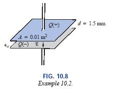
![ELETRI FIELD When a potential difference of volts is applied across the two plates separated by a distance of d, the electric field strength, E, between the plates is determined by: Ɛ E d [ ] m d v](/docs-images/89/97985153/images/3-1.jpg "The electric field strength, is represented graphically by electric flux lines (i.e. lines of force). These lines of force always extend from a positively charged body to a negatively charged body.")
3 ELETRI FIELD When a potential difference of volts is applied across the two plates separated by a distance of d, the electric field strength, E, between the plates is determined by: Ɛ E d [ ] m d v The electric field strength, is represented graphically by electric flux lines (i.e. lines of force). These lines of force always extend from a positively charged body to a negatively charged body. They extend Perpendicular to the charged surfaces and never intersect. Electric Flux Lines A capacitor stores energy in the form of electrical field (i.e. voltage) that is established by the opposite charges on the two plates. 3

 at")
4 ELETRI FIELD The force exerted between two charged particles is given by oulomb s law: F kq1q 2 d 2 The electric field strength, ε, at a given point is the force, F, acting on a unit positive charge (Q 1 1) at that point: 4

5 APAITOR OPERATION When the capacitor is in a neutral state, both plates have an equal number of free electrons. (Insulator) 5
6 APAITOR OPERATION When a voltage is applied across the plates, electrons are attracted by the positive side of the battery and electrons are repelled by the negative side of the battery. For every electron that leaves one side of the plate, an electron travels to the other side of the plate. The electrons can not pass through the dielectric so that plate A starts storing electrons and plate B effectively starts storing positive charges. This process lasts until the plates are fully charged to a potential difference of the source. The result is a positive charge on plate B and a negative charge on plate A. B e - e - (Electric flux lines) A harging phase process 6
7 APAITOR OPERATION URRENT APPEARS TO BE FLOWING FROM THE NEGATIE SIDE OF THE BATTERY TOWARD THE POSITIE SIDE THROUGH THE APAITOR. IN FAT IT IS NOT SO, BEAUSE NO ELETRONS AN FLOW THROUGH THE INSULATOR MATERIAL OR GAP BETWEEN THE PLATES (DIELETRI) THERE ARE IN FAT TWO SEPARATE URRENTS FROM THE BATTERY TO THE APAITOR FROM THE APAITOR TO THE BATTERY 7

8 APAITOR OPERATION If the capacitor is disconnected from the source, it retains the stored charge for a certain period of time (depends on capacitor type and amount of voltage). apacitors are not perfect. Ideal insulators have infinite resistance. Actual insulators have some very high resistance. The electrons on plate A will attract to plate B - Leakage current takes place. Once all the electrons have been neutralized the capacitor has lost all of its charge. B A apacitors cannot be used as a replacement of batteries as they slowly discharge over time. However, they are used to provide a short life supply of voltage (i.e. surge protectors, smoke alarms) 8
9 APAITANE apacitance is a measure of a capacitor s ability to store charge on its plates. As such, the amount of charge a capacitor can Michael Faraday store per unit of voltage across its plate is called capacitance (Q, ). A capacitor is said to have a 1 Farad Q Q capacitance when 1 oulomb of charge is deposited on the plates with A 1 volt potential difference across it. Q apacitance FARADS [ F ] Q harge OULOMBS [ ] oltage OLTS [ ] 1 1 F 1 The charge across a capacitor is proportional to the voltage across it: Q ( t) ( t) 9

10 APAITANE apacitance can be computed as follows: Michael Faraday ε ε r o A d Permittivity for vacuum ε o 8.85 x F/m APAITANE [ F ] A AREA OF THE PLATES [ m 2 ] d DISTANE BETWEEN PLATES [ m ] ε DIELETRI PERMITTIITY 10
11 APAITANE Eq 1: Sub Eq 3 into Eq 2: Sub Eq 4 into Eq 1: Ԑ Ԑ d Q Eq 2: Eq 3: Qd Ad ε Eq 4: Qd εa Q A ε ε A d Michael Faraday Q Ԑ ε A 11


12 APAITANE Michael Faraday 12

13 APAITOR OLTAGE BREAKDOWN Every capacitor has a voltage rating. A user must not exceed this voltage rating (i.e. voltage breakdown). oltage breakdown is the voltage required to break the bonds within the dielectric that will create current flow in the dielectric through the plates When breakdown occurs, the characteristic of the capacitor becomes that of a conductor (i.e. capacitor shorted) Lightning is an example of breakdown: The potential between the clouds and the earth is so high that charge can pass from one to the other through the atmosphere (which acts as the dielectric) louds Atmosphere Earth 13
 50 uf d. (5)(4)/(1/8) (1000 pf) (160)(1000 pf) 0.")
14 8.85x10 12 εr A d a. 3(5 uf) 15 uf b. ½ (0.1 uf) 0.05 uf c. 2.5(20 uf) 50 uf d. (5)(4)/(1/8) (1000 pf) (160)(1000 pf) 0.16 uf 14
15 15

16 b. or Q 16
17 Assume the breakdown voltage for this capacitor is 200 /mil. 17


18 APAITORS There are many types of capacitors and they are characterized by the type of dielectric material used between the conducting plates. eramic Disc Tantalum Polypropylene Film Polyester Film Mylar 18


19 APAITORS There are many types of capacitors and they are characterized by the type of dielectric material used between the conducting plates. ariable apacitors SMT apacitor Non-polarized Electrolytic Radial Lead Axial Lead ariable Electrolytic 19

20 APAITORS There are many types of capacitors and they are characterized by the type of dielectric material used between the conducting plates. eramic Disk apacitors 20

21 APAITORS There are many types of capacitors and they are characterized by the type of dielectric material used between the conducting plates. Axial Lead Plastic Film Dielectric Tubular apacitors 21

22 APAITORS There are many types of capacitors and they are characterized by the type of dielectric material used between the conducting plates. Tantalum Electrolytic apacitors 22
23 APAITOR ODES eramic Disc 100,000 pf 100 nf.1uf 23
. Most of the smaller caps have two or three numbers printed on them, The alue is in pf.")
24 APAITOR ODES Other capacitors may just have 0.1 or 0.01 printed on them. If so, this means a value in uf. Thus 0.1 means just 0.1 uf. alues marked as 50 or 330 means just pf. Electrolytic and large types of apacitors usually have the value printed on them (i.e. 470uF 25). Most of the smaller caps have two or three numbers printed on them, The alue is in pf. 105 means 10 x pF 1000 nf 1 uf. Letters added to the value represent the tolerance and in some cases represent the temperature coefficient. A 474J ceramic capacitor means 47 x pF and J 5% tolerance. ( pF 470nF 0.47uF). 24

25 APAITOR ODES 25
26 APAITOR ODES 26
. Gnd apacitive coupling circuit For dc circuit analysis, or Steady State circuit analysis, a capacitor is modeled as an open.")
27 APAITOR URRENT & OLTAGE RELATIONSHIP dq( t) i( t) and for a capacitor dt d( v( t)) dv( t) i( t) i( t) dt dt 1 We get : dv( t) i( t) dt 1 v( t) 5v i( t) dt q(t) v(t) If v(t) k i(t) 0, then the capacitor acts like an open to dc (i.e. blocks dc - Steady State). Gnd apacitive coupling circuit For dc circuit analysis, or Steady State circuit analysis, a capacitor is modeled as an open. 27
28 R IRUIT STEADY STATE ANALYSIS When a capacitor has reached Steady State it is modeled as an open circuit. Find the current I when the circuit has reached steady state. I I 48 v I 8 6k ma 28
29 APAITOR URRENT & OLTAGE The power delivered is : dv( t) p( t) i( t) v( t) i( t) dt The energy stored in a capacitor is found to be : dw c(t) We know : p(t) dt τ τ dv( t) w ( t) p( t) dt ( ) v t dt dt w w ( t) ( t) v v 2 2 ( t) ( t) v( τ ) v( ) q ( t) Assuming that J since v(t) v( ) 0 q(t) If v (t) K: o dv(t)/dt 0, p(t) 0 If v (t) is an instantaneous change: o dv(t)/dt and p(t) Power can only be finite, as such the voltage across a capacitor cannot change instantaneously. 29
30 APAITORS The voltage across a 5-uF capacitor has the waveform shown below. Determine the current 0 i( t) i( t) 6ms 6 24 i( t) 5x10 6 t 8ms 5x10 t 5x i( t) ma ma 60 dv( t) dt ma 30
31 APAITORS - Example w ( t) The voltage across a 5-uF capacitor has the waveform shown below. Determine the Energy at t 6ms. 1 2 v 2 ( t) w (6 1 ms) (5x )(24) w ( 6 ms) 1440 uj 2 31
32 APAITORS IN SERIES 32 Using KL: ) ( ) ( ) ( ) ( ) ( t v t v t v t v t v N dt t i t v i i ) ( 1 ) ( dt t i t v n I i i ) ( 1 ) ( 1 dt t i t v S ) ( 1 ) ( N n I i S apacitors in series act like resistors in parallel urrent is the same through each element in a series circuit T +
33 APAITORS IN PARALLEL Using KL: ) ( ) ( ) ( ) ( ) ( t i t i t i t i t i N dt t dv dt t dv dt t dv dt t dv t i N ) ( ) ( ) ( ) ( ) ( apacitors in parallel act like resistors in series 33 N N i i P N i i dt t dv t i ) ( ) ( oltage is the same across each branch in a parallel circuit
 fires.")
 is about 10 turns of heavy wire. The secondary (L2) is about 1000 turns of thin wire ( 1:100 ratio).")
34 TESLA OIL A high voltage power supply charges up a capacitor 1. When the capacitor reaches a high enough voltage, the spark gap (switch) fires. When the spark gap fires, the energy stored up in the capacitor dumps into a 1:100 step-up transformer. The primary (L1) is about 10 turns of heavy wire. The secondary (L2) is about 1000 turns of thin wire ( 1:100 ratio). Feed in 10,000 volts, get out 1,000,000 volts. It all happens at a rate of over 120 times per second, often generating multiple discharges in many directions 34
 capacitors only.")
35 APAITORS IN SERIES & PARALLEL Tesla coil designs require a capacitor with large voltage breakdown. Placing capacitors is series increases the voltage breakdown (add each voltage breakdown). However, placing capacitors in series reduces the total capacitance. This banks of capacitors in series are placed in parallel. Use Power factor correction (PF) capacitors only. These are used to correct the power factor of the A connected to the Neon Sign Transformer (NST). 35

36 APAITORS IN SERIES & PARALLEL MM: Multi Mini apacitor 36
37 When EET11 TRANSIENT ANALYSIS - APAITOR HARGING PHASE t 0 v (0 ) t 0 + switch is closed v (0 + ) t I R > ( t) ( t) ( t) 0 E R Ee E e t R t R E 1 e R t R ( t) + ( t) The R ircuit provides a 1 st order Differential equation. Solving this equation results in: v (0 ) 0 apacitor is modeled as a short apacitor is modeled as an open 37
38 TRANSIENT ANALYSIS - APAITOR HARGING PHASE apacitor harging E E/R voltage current time time
 0 E/R I ( t) E R e t R τ R [s] R ( t) Ee t R")
39 TRANSIENT ANALYSIS - APAITOR HARGING PHASE t 0 ( t) E 1 e t R E harging Phase v (0 ) 0 E/R I ( t) E R e t R τ R [s] R ( t) Ee t R E 39
40 When EET11 TRANSIENT ANALYSIS - APAITOR HARGING PHASE t 0 v (0 ) t 0 + switch is closed v (0 + ) t I R > ( t) ( t) ( t) 0 E i R E E ( E ) t R ( E ) e i e R ( t) t R i e + t R ( t) The R ircuit provides a 1 st order Differential equation. Solving this equation results in: v (0 ) i I E i R E i i apacitor is modeled as a battery apacitor is modeled as an open 40
 E R t i R e E i R v (0 ) i E i R τ R R ( t) t R ( E ) e i")
41 TRANSIENT ANALYSIS - APAITOR HARGING PHASE or ( t) E ( t) E + ( E ) ( E) i i e e t R t R E t 0 I ( t) E R t i R e E i R v (0 ) i E i R τ R R ( t) t R ( E ) e i 41


42 TRANSIENT ANALYSIS - APAITOR HARGING PHASE R follows this curve Steady State Definition f( ) f(5τ ) R, I 42

43 TRANSIENT ANALYSIS - APAITOR HARGING PHASE 43

44 TRANSIENT ANALYSIS - APAITOR HARGING PHASE 44
45 TRANSIENT ANALYSIS - APAITOR DISHARGE PHASE t 0 v (0 ) 0 ( t) Ee t R E t t o I c ( t) E R e t P1 harging P2 Discharging phase E R Note the current reversal t t o R ( t) Ee t R E Note the voltage reversal 45
46 TRANSIENT ANALYSIS - APAITOR DISHARGE PHASE - 46
47 TRANSIENT ANALYSIS - APAITOR DISHARGE PHASE If the charging phase is disrupted before reaching the supply voltage, the capacitive voltage will be less then E. We call it f. 47

48 SOURE ONERSION A voltage source can be converted to a current source and vice-versa producing equal behaviors across its load. 48

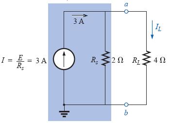
49 SOURE ONERSION 49
50 TRANSIENT ANALYSIS 50
51 TRANSIENT ANALYSIS 51
52 TRANSIENT ANALYSIS 52
53 TRANSIENT ANALYSIS 53
54 SUPERPOSITION Given a linear circuit, (i.e. described by a set of linear algebraic equations), the superposition analysis technique provides a mean to determine a voltage drop or current by calculating the contribution of each source acting independently and algebraically adding each contribution. Procedure: 1. Remove all sources except one of them by replacing current sources with an open replacing voltage sources with a short retaining all internal resistance 2. alculate the desired voltage drop or branch current from that source paying close attention to polarity or direction 3. Repeat steps 1 and 2 for each additional source acting independently 4. Algebraically add each sources contribution 54
55 SUPERPOSITION Example 1 For the circuit below, find A using superposition: A S1 ontribution: A + ' A (2.7k)(1.8k) k + 1.8k 1.2k k ' A v 55
56 SUPERPOSITION Example 1 For the circuit below, find A using superposition: A S2 ontribution: '' A (2.7k)(1.2k) k + 1.2k 1.8k k A - '' A 11.37v 56
57 SUPERPOSITION Example 1 ' '' A A + A 4.74v 11.37v v 57
58 SUPERPOSITION Example 2 For the circuit below, find A and B using superposition: A B 58
59 SUPERPOSITION Example 2 S1 ontribution: R2 // R Ω RL Ω 6705 Ω R3 // 6705 Ω 5021 Ω A B ' A 40(5.021k ) 4k k ' B 22.26(4.705k) 2k k ' A 22.26v ' B 15.62v 59
60 SUPERPOSITION Example 2 S2 ontribution: R1// R3 3.33k Ω RL k Ω 5.33k Ω R4 // 5.33k Ω 4997 Ω A B '' B 25(4.997k) 5k k '' A 12.49(3.33k) 2k k '' B 12.49v '' A 7.80v 60
61 SUPERPOSITION Example 2 A B ' ' A v B v '' '' A 7. 80v B v ' '' ' '' A A + A v B B + B v 61
62 SUPERPOSITION Example 3 For the circuit below, find A using superposition: A 62
63 SUPERPOSITION Example 3 A IS1 ontribution: R2 // (R3+R4) 172 Ω ma I A I ' A 100(172) I ' A 20.18mA 63
64 SUPERPOSITION Example 3 S2 ontribution: R1 // (R3+R4) 367 Ω A I I '' A '' A ' A (367) ma I A I '' A 18.38mA 64
65 SUPERPOSITION Example 3 ' I A mA '' I A mA A v A I I I ' A + I '' A 20.18mA 18.38mA A 1.80 ma(680ω) I 1.80mA A 1.224v 65
66 This image cannot currently be displayed. EET11 THEENIN S THEOREM A two-terminal linear network connected to a load can be replaced with an equivalent circuit consisting of an independent voltage source called TH in series with a resistor R TH such that the current-voltage relationship at the load is unchanged. Procedure: 1. Identify and remove the load 2. Label the load terminals 3. Look in the load terminals and calculate TH 4. Remove all sources by replacing: voltage sources with a short current sources with an open If the source has an internal resistance, keep the resistance in the circuit 5. Look in the load terminals and calculate R TH 6. reate a series circuit consisting of TH, R TH, and the load 7. alculate the load current or voltage as desired 66
67 This image cannot currently be displayed. EET11 THEENIN S THEOREM Example 1 Identify Load, remove load, label terminals, & find TH a TH 10(8.2k) 3.9k + 8.2k b TH 6.77v 67
68 This image cannot currently be displayed. EET11 THEENIN S THEOREM Example 1 Replace voltage sources with a short, current sources with an open & find R TH a R TH 3.9k(8.2k) 3.9k + 8.2k + 4.7k R TH 7.34kΩ b 68
69 This image cannot currently be displayed. EET11 THEENIN S THEOREM Example 1 onnect the load to the equivalent circuit across terminals a & b 7.34 kω a 6.77v b 69
70 This image cannot currently be displayed. EET11 THEENIN S THEOREM Example kω a 6.77v RL b 6.77(3.3k) 7.34k + 3.3k RL 2.10v 70

71 This image cannot currently be displayed. EET11 THEENIN S THEOREM Example kω a 6.77v I RL b k + 3.3k I RL uA 71
72 This image cannot currently be displayed. EET11 THEENIN S THEOREM Example 2 I I R3 R3 27mA(2k) 7k + 2k 6 ma TH1 6mA(3k ) 18v 72
73 This image cannot currently be displayed. EET11 THEENIN S THEOREM Example 2 TH 2 24(3k) 2k + 3k + 4k TH 2 TH 8.0v TH1 + TH v 73
74 This image cannot currently be displayed. EET11 THEENIN S THEOREM R TH 6k(3k) 6k + 3k + 1k R TH 3kΩ 74
75 This image cannot currently be displayed. EET11 THEENIN S THEOREM 3kΩ 26v 75
76 This image cannot currently be displayed. EET11 THEENIN S THEOREM 3kΩ 26v RL 26(3.3k) 3k + 3.3k RL 13.61v 76
77 This image cannot currently be displayed. EET11 THEENIN S THEOREM 3kΩ 26v I RL 3k k I RL 4.12mA 77
78 R IRUIT THEENIN EQUIALENT 78

79 R IRUIT THEENIN EQUIALENT 79
80 R IRUIT THEENIN EQUIALENT 80
81 R IRUIT THEENIN EQUIALENT 81
82 FORMULAS E Ɛ d Q ε r ε o A d v i dt p ( t) i( t) v( t) 1 w ( t) v 2 ( t) 2 1 n 1 I S 1 N P i i 1 i E τ R ( t) ( t) R + harging v (0 ) 0 ( t) E 1 e E I ( t) e R R ( t) Ee t R t R t R harging v (0 ) i R ( E ) e the voltage across a capacitor cannot change instantaneously ( t) E ( t) E + I R ( t) ( t) Steady State: t 5τ ( E ) ( E) i E Steady State is an open circuit i i e e t i R e t R t R t Discharging Phase: I ( t) c ( t) R ( t) Ee E R t R e Ee t R t R 82
Chapter 2: Capacitor And Dielectrics
 hapter 2: apacitor And Dielectrics In this chapter, we are going to discuss the different ways that a capacitor could be arranged in a circuit and how its capacitance could be increased. Overview apacitor
CAPACITANCE. Capacitor. Because of the effect of capacitance, an electrical circuit can store energy, even after being de-energized.
 D ircuits APAITANE APAITANE Because of the effect of capacitance, an electrical circuit can store energy, even after being de-energized. EO 1.5 EO 1.6 EO 1.7 EO 1.8 EO 1.9 DESRIBE the construction of a
Look over. examples 1, 2, 3, 5, 6. Look over. Chapter 25 section 1-8. Chapter 19 section 5 Example 10, 11
 PHYS Look over hapter 5 section -8 examples,, 3, 5, 6 PHYS Look over hapter 7 section 7-9 Examples 8, hapter 9 section 5 Example 0, Things to Know ) How to find the charge on a apacitor. ) How to find
Introduction to AC Circuits (Capacitors and Inductors)
") Introduction to AC Circuits (Capacitors and Inductors) Amin Electronics and Electrical Communications Engineering Department (EECE) Cairo University elc.n102.eng@gmail.com http://scholar.cu.edu.eg/refky/
Introduction to AC Circuits (Capacitors and Inductors) Amin Electronics and Electrical Communications Engineering Department (EECE) Cairo University elc.n102.eng@gmail.com http://scholar.cu.edu.eg/refky/
Chapter 10 EMT1150 Introduction to Circuit Analysis
 Chapter 10 EM1150 Introduction to Circuit Analysis Department of Computer Engineering echnology Fall 2018 Prof. Rumana Hassin Syed Chapter10 Capacitors Introduction to Capacitors he Electric Field Capacitance
Chapter 2: Capacitors And Dielectrics
 hapter 2: apacitors And Dielectrics 2.1 apacitance and capacitors in series and parallel L.O 2.1.1 Define capacitance and use capacitance apacitor is a device that is capable of storing electric charges
Capacitor Construction
 Capacitor Construction Topics covered in this presentation: Capacitor Construction 1 of 13 Introduction to Capacitors A capacitor is a device that is able to store charge and acts like a temporary, rechargeable
CIRCUIT ELEMENT: CAPACITOR
 CIRCUIT ELEMENT: CAPACITOR PROF. SIRIPONG POTISUK ELEC 308 Types of Circuit Elements Two broad types of circuit elements Ati Active elements -capable of generating electric energy from nonelectric energy
ENGR 2405 Chapter 6. Capacitors And Inductors
 ENGR 2405 Chapter 6 Capacitors And Inductors Overview This chapter will introduce two new linear circuit elements: The capacitor The inductor Unlike resistors, these elements do not dissipate energy They
Electro - Principles I
 Electro - Principles I Capacitance The Capacitor What is it? Page 8-1 The capacitor is a device consisting essentially of two conducting surfaces separated by an insulating material. + Schematic Symbol
The Basic Capacitor. Water Tower / Capacitor Analogy. "Partnering With Our Clients for Combined Success"
 CAPACITOR BASICS I How s Work The Basic A capacitor is an electrical device which serves to store up electrical energy for release at a predetermined time. In its most basic form, it is comprised of three
The Basic Capacitor. Dielectric. Conductors
 Chapter 9 The Basic Capacitor Capacitors are one of the fundamental passive components. In its most basic form, it is composed of two conductive plates separated by an insulating dielectric. The ability
Physics Electricity and Magnetism Lecture 06 - Capacitance. Y&F Chapter 24 Sec. 1-6
 Physics - lectricity and Magnetism Lecture 6 - apacitance Y&F hapter 4 Sec. - 6 Overview Definition of apacitance alculating the apacitance Parallel Plate apacitor Spherical and ylindrical apacitors apacitors
AP Physics C - E & M. Slide 1 / 39 Slide 2 / 39. Slide 4 / 39. Slide 3 / 39. Slide 6 / 39. Slide 5 / 39. Capacitance and Dielectrics.
 Slide 1 / 39 Slide 2 / 39 P Physics & M apacitance and ielectrics 20151205 www.njctl.org Slide 3 / 39 apacitors capacitor is any two conductors seperated by an insulator, such as air or another material.
Chapter 29. Electric Potential: Charged Conductor
 hapter 29 Electric Potential: harged onductor 1 Electric Potential: harged onductor onsider two points (A and B) on the surface of the charged conductor E is always perpendicular to the displacement ds
Capacitors. Example 1
 Physics 30AP Resistors and apacitors I apacitors A capacitor is a device for storing electrical charge that consists of two conducting objects placed near one another but not touching. A A typical capacitor
Chapter 28. Direct Current Circuits
 Chapter 28 Direct Current Circuits Circuit Analysis Simple electric circuits may contain batteries, resistors, and capacitors in various combinations. For some circuits, analysis may consist of combining
Experiment FT1: Measurement of Dielectric Constant
 Experiment FT1: Measurement of Dielectric Constant Name: ID: 1. Objective: (i) To measure the dielectric constant of paper and plastic film. (ii) To examine the energy storage capacity of a practical capacitor.
General Physics II. Conducting concentric spheres Two concentric spheres of radii R and r. The potential difference between the spheres is
 apacitors and Dielectrics The ideas of energy storage in E-fields can be carried a step further by understanding the concept of "apacitance" onsider a sphere with a total charge, Q, and a radius, R From
FREE Download Study Package from website: &
 EXERISE- * MARK IS MORE THAN ONE ORRET QUESTIONS. SETION A : DEFINITION OF APAIT ITANE A. A. When 0µ charge is given to an isolated conductor of capacitance 5µF. Find out following (i) Potential of the
Chapter 24: Capacitance and Dielectrics
 hapter 4: apacitance and Dielectrics apacitor: two conductors (separated by an insulator) usually oppositely charged a + b - ab proportional to charge = / ab (defines capacitance) units: F = / pc4: The
Lecture 20. March 22/24 th, Capacitance (Part I) Chapter , Pages
 Chapter , Pages") Lecture 0 March /4 th, 005 Capacitance (Part I) Reading: Boylestad s Circuit Analysis, 3 rd Canadian Edition Chapter 10.1-6, Pages 8-94 Assignment: Assignment #10 Due: March 31 st, 005 Preamble: Capacitance
Lecture 0 March /4 th, 005 Capacitance (Part I) Reading: Boylestad s Circuit Analysis, 3 rd Canadian Edition Chapter 10.1-6, Pages 8-94 Assignment: Assignment #10 Due: March 31 st, 005 Preamble: Capacitance
Physics Electricity and Magnetism Lecture 06 - Capacitance. Y&F Chapter 24 Sec. 1-6
 Physics - lectricity and Magnetism Lecture 6 - apacitance Y&F hapter 4 Sec. - 6 Overview Definition of apacitance alculating the apacitance Parallel Plate apacitor Spherical and ylindrical apacitors apacitors
Electricity and Magnetism. Capacitance
 Electricity and Magnetism apacitance Sources of Electric Potential A potential difference can be created by moving charge from one conductor to another. The potential difference on a capacitor can produce
Capacitance and capacitors. Dr. Loai Afana
 apacitance and capacitors apacitors apacitors are devices that store energy in an electric field. apacitors are used in many every-day applications Heart defibrillators amera flash units apacitors are
Electronics Capacitors
 Electronics Capacitors Wilfrid Laurier University October 9, 2015 Capacitor an electronic device which consists of two conductive plates separated by an insulator Capacitor an electronic device which consists
Chapt ha e pt r e r 9 Capacitors
 Chapter 9 Capacitors Basics of a Capacitor In its simplest form, a capacitor is an electrical device constructed of two parallel plates separated by an insulating material called the dielectric In the
Chapter 6 Objectives
 hapter 6 Engr8 ircuit Analysis Dr urtis Nelson hapter 6 Objectives Understand relationships between voltage, current, power, and energy in inductors and capacitors; Know that current must be continuous
Chapter 13. Capacitors
 Chapter 13 Capacitors Objectives Describe the basic structure and characteristics of a capacitor Discuss various types of capacitors Analyze series capacitors Analyze parallel capacitors Analyze capacitive
Basic RL and RC Circuits R-L TRANSIENTS: STORAGE CYCLE. Engineering Collage Electrical Engineering Dep. Dr. Ibrahim Aljubouri
 st Class Basic RL and RC Circuits The RL circuit with D.C (steady state) The inductor is short time at Calculate the inductor current for circuits shown below. I L E R A I L E R R 3 R R 3 I L I L R 3 R
First Order RC and RL Transient Circuits
 First Order R and RL Transient ircuits Objectives To introduce the transients phenomena. To analyze step and natural responses of first order R circuits. To analyze step and natural responses of first
Chapter 24 Capacitance and Dielectrics
 Chapter 24 Capacitance and Dielectrics 1 Capacitors and Capacitance A capacitor is a device that stores electric potential energy and electric charge. The simplest construction of a capacitor is two parallel
Energy Stored in Capacitors
 Energy Stored in Capacitors U = 1 2 qv q = CV U = 1 2 CV 2 q 2 or U = 1 2 C 37 Energy Density in Capacitors (1) We define the, u, as the electric potential energy per unit volume Taking the ideal case
Chapter 24: Capacitance and Dielectrics. Capacitor: two conductors (separated by an insulator) usually oppositely charged. (defines capacitance)
 usually oppositely charged. (defines capacitance)") hapter 4: apacitance and Dielectrics apacitor: two conductors (separated by an insulator) usually oppositely charged a b - ab proportional to charge / ab (defines capacitance) units: F / pc4: The parallel
hapter 4: apacitance and Dielectrics apacitor: two conductors (separated by an insulator) usually oppositely charged a b - ab proportional to charge / ab (defines capacitance) units: F / pc4: The parallel
Louisiana State University Physics 2102, Exam 2, March 5th, 2009.
 PRINT Your Name: Instructor: Louisiana State University Physics 2102, Exam 2, March 5th, 2009. Please be sure to PRINT your name and class instructor above. The test consists of 4 questions (multiple choice),
Where C is proportionally constant called capacitance of the conductor.
 PITNE Page #. INTROUTION capacitor can store energy in the form of potential energy in an electric field. In this chapter well discuss the capacity of conductors to hold charge and energy.. apacitance
Direct Current (DC) Circuits
 Circuits") Direct Current (DC) Circuits NOTE: There are short answer analysis questions in the Participation section the informal lab report. emember to include these answers in your lab notebook as they will be
Direct Current (DC) Circuits NOTE: There are short answer analysis questions in the Participation section the informal lab report. emember to include these answers in your lab notebook as they will be
Capacitors. Charging a Capacitor. Charge and Capacitance. L05: Capacitors and Inductors
 L05: Capacitors and Inductors 50 Capacitors 51 Outline of the lecture: Capacitors and capacitance. Energy storage. Capacitance formula. Types of capacitors. Inductors and inductance. Inductance formula.
Capacitance. PHY2049: Chapter 25 1
 apacitance PHY049: hapter 5 1 oulomb s law Electric fields Equilibrium Gauss law What You Know: Electric Fields Electric fields for several charge configurations Point Dipole (along axes) Line Plane (nonconducting)
E40M Capacitors. M. Horowitz, J. Plummer, R. Howe
 E40M Capacitors 1 Reading Reader: Chapter 6 Capacitance A & L: 9.1.1, 9.2.1 2 Why Are Capacitors Useful/Important? How do we design circuits that respond to certain frequencies? What determines how fast
iclicker A metal ball of radius R has a charge q. Charge is changed q -> - 2q. How does it s capacitance changed?
 1 iclicker A metal ball of radius R has a charge q. Charge is changed q -> - 2q. How does it s capacitance changed? q A: C->2 C0 B: C-> C0 C: C-> C0/2 D: C->- C0 E: C->-2 C0 2 iclicker A metal ball of
AP Physics C. Electric Circuits III.C
 AP Physics C Electric Circuits III.C III.C.1 Current, Resistance and Power The direction of conventional current Suppose the cross-sectional area of the conductor changes. If a conductor has no current,
RADIO AMATEUR EXAM GENERAL CLASS
 RAE-Lessons by 4S7VJ 1 CHAPTER- 2 RADIO AMATEUR EXAM GENERAL CLASS By 4S7VJ 2.1 Sine-wave If a magnet rotates near a coil, an alternating e.m.f. (a.c.) generates in the coil. This e.m.f. gradually increase
Trade of Electrician Standards Based Apprenticeship Capacitance Phase 2 Module No. 2.1 Unit No COURSE NOTES
 Trade of Electrician Standards Based Apprenticeship Capacitance Phase 2 Module No. 2.1 Unit No. 2.1.8 COURSE NOTES Certification & Standards Department Created by Gerry Ryan - Galway TC Revision 1 April
EDEXCEL NATIONAL CERTIFICATE. UNIT 38 ELECTRICAL and ELECTRONIC PRINCIPLES OUTCOME 2
 EDEXCEL NATIONAL CERTIFICATE UNIT 38 ELECTRICAL and ELECTRONIC PRINCIPLES OUTCOME 2 Electric fields and capacitors Electric fields: electrostatics, charge, electron movement in field, force on unit charge,
Capacitors. Chapter How capacitors work Inside a capacitor
 Chapter 6 Capacitors In every device we have studied so far sources, resistors, diodes and transistors the relationship between voltage and current depends only on the present, independent of the past.
The next two questions pertain to the situation described below. Consider a parallel plate capacitor with separation d:
 PHYS 102 Exams Exam 2 PRINT (A) The next two questions pertain to the situation described below. Consider a parallel plate capacitor with separation d: It is connected to a battery with constant emf V.
Notes on Electric Circuits (Dr. Ramakant Srivastava)
") Notes on Electric ircuits (Dr. Ramakant Srivastava) Passive Sign onvention (PS) Passive sign convention deals with the designation of the polarity of the voltage and the direction of the current arrow
Notes on Electric ircuits (Dr. Ramakant Srivastava) Passive Sign onvention (PS) Passive sign convention deals with the designation of the polarity of the voltage and the direction of the current arrow
Conceptually, a capacitor consists of two conducting plates. Capacitors: Concept
 apacitors and Inductors Overview Defining equations Key concepts and important properties Series and parallel equivalents Integrator Differentiator Portland State University EE 221 apacitors and Inductors
Chapter 24 Capacitance and Dielectrics
 Chapter 24 Capacitance and Dielectrics 1 Capacitors and Capacitance A capacitor is a device that stores electric potential energy and electric charge. The simplest construction of a capacitor is two parallel
Capacitance and Dielectrics
 Slide 1 / 39 Capacitance and Dielectrics 2011 by Bryan Pflueger Capacitors Slide 2 / 39 A capacitor is any two conductors seperated by an insulator, such as air or another material. Each conductor has
Coulomb s constant k = 9x10 9 N m 2 /C 2
 1 Part 2: Electric Potential 2.1: Potential (Voltage) & Potential Energy q 2 Potential Energy of Point Charges Symbol U mks units [Joules = J] q 1 r Two point charges share an electric potential energy
CHAPTER FOUR MUTUAL INDUCTANCE
 CHAPTER FOUR MUTUAL INDUCTANCE 4.1 Inductance 4.2 Capacitance 4.3 Serial-Parallel Combination 4.4 Mutual Inductance 4.1 Inductance Inductance (L in Henry is the circuit parameter used to describe an inductor.
[1] (b) Fig. 1.1 shows a circuit consisting of a resistor and a capacitor of capacitance 4.5 μf. Fig. 1.1
![[1] (b) Fig. 1.1 shows a circuit consisting of a resistor and a capacitor of capacitance 4.5 μf. Fig. 1.1](/thumbs/81/83276652.jpg "[1] (b) Fig. 1.1 shows a circuit consisting of a resistor and a capacitor of capacitance 4.5 μf. Fig. 1.1") 1 (a) Define capacitance..... [1] (b) Fig. 1.1 shows a circuit consisting of a resistor and a capacitor of capacitance 4.5 μf. S 1 S 2 6.3 V 4.5 μf Fig. 1.1 Switch S 1 is closed and switch S 2 is left
1 (a) Define capacitance..... [1] (b) Fig. 1.1 shows a circuit consisting of a resistor and a capacitor of capacitance 4.5 μf. S 1 S 2 6.3 V 4.5 μf Fig. 1.1 Switch S 1 is closed and switch S 2 is left
Lecture 24. April 5 th, Magnetic Circuits & Inductance
 Lecture 24 April 5 th, 2005 Magnetic Circuits & Inductance Reading: Boylestad s Circuit Analysis, 3 rd Canadian Edition Chapter 11.1-11.5, Pages 331-338 Chapter 12.1-12.4, Pages 341-349 Chapter 12.7-12.9,
RC Circuits. Equipment: Capstone with 850 interface, RLC circuit board, 2 voltage sensors (no alligator clips), 3 leads V C = 1
, 3 leads V C = 1") R ircuits Equipment: apstone with 850 interface, RL circuit board, 2 voltage sensors (no alligator clips), 3 leads 1 Introduction The 3 basic linear circuits elements are the resistor, the capacitor, and
R ircuits Equipment: apstone with 850 interface, RL circuit board, 2 voltage sensors (no alligator clips), 3 leads 1 Introduction The 3 basic linear circuits elements are the resistor, the capacitor, and
FE Review 2/2/2011. Electric Charge. Electric Energy ELECTRONICS # 1 FUNDAMENTALS
 FE eview ELECONICS # FUNDAMENALS Electric Charge 2 In an electric circuit there is a conservation of charge. he net electric charge is constant. here are positive and negative charges. Like charges repel
Designing Information Devices and Systems I Fall 2018 Lecture Notes Note Introduction to Capacitive Touchscreen
 EES 16A Designing Information Devices and Systems I Fall 2018 Lecture Notes Note 16 16.1 Introduction to apacitive Touchscreen We ve seen how a resistive touchscreen works by using the concept of voltage
Chapter 14 CAPACITORS IN AC AND DC CIRCUITS
 hapter 14--apacitors hapter 14 APAITORS IN A AND D IRUITS So far, all we have discussed have been electrical elements in which the voltage across the element is proportional to the current through the
Some Important Electrical Units
 Some Important Electrical Units Quantity Unit Symbol Current Charge Voltage Resistance Power Ampere Coulomb Volt Ohm Watt A C V W W These derived units are based on fundamental units from the meterkilogram-second
PROBLEMS TO BE SOLVED IN CLASSROOM
 PROLEMS TO E SOLVED IN LSSROOM Unit 0. Prerrequisites 0.1. Obtain a unit vector perpendicular to vectors 2i + 3j 6k and i + j k 0.2 a) Find the integral of vector v = 2xyi + 3j 2z k along the straight
CAPACITANCE. Figure 1(a). Figure 1(b).
. Figure 1(b).") Reading 11 Ron Bertrand VK2DQ http://www.radioelectronicschool.com CAPACITANCE In this reading we are going to talk about capacitance. I have to make a distinction here between capacitor and capacitance.
Reading 11 Ron Bertrand VK2DQ http://www.radioelectronicschool.com CAPACITANCE In this reading we are going to talk about capacitance. I have to make a distinction here between capacitor and capacitance.
Introduction to Electric Circuit Analysis
 EE110300 Practice of Electrical and Computer Engineering Lecture 2 and Lecture 4.1 Introduction to Electric Circuit Analysis Prof. Klaus Yung-Jane Hsu 2003/2/20 What Is An Electric Circuit? Electrical
Capacitors. David Frazier and John Ingram
 Capacitors David Frazier and John Ingram Introduction Used in most electronic devices Comes in a variety of sizes Basic Function The basic function of a capacitor is to store energy. Common usage include
Capacitance. A capacitor consists of two conductors that are close but not touching. A capacitor has the ability to store electric charge.
 Capacitance A capacitor consists of two conductors that are close but not touching. A capacitor has the ability to store electric charge. a) Parallel-plate capacitor connected to battery. (b) is a circuit
Circuits. 1. The Schematic
 + ircuits 1. The Schematic 2. Power in circuits 3. The Battery 1. eal Battery vs. Ideal Battery 4. Basic ircuit nalysis 1. oltage Drop 2. Kirchoff s Junction Law 3. Series & Parallel 5. Measurement Tools
Capacitors are devices which can store electric charge. They have many applications in electronic circuits. They include:
 CAPACITORS Capacitors are devices which can store electric charge They have many applications in electronic circuits They include: forming timing elements, waveform shaping, limiting current in AC circuits
Basic Electronics. Introductory Lecture Course for. Technology and Instrumentation in Particle Physics Chicago, Illinois June 9-14, 2011
 Basic Electronics Introductory Lecture Course for Technology and Instrumentation in Particle Physics 2011 Chicago, Illinois June 9-14, 2011 Presented By Gary Drake Argonne National Laboratory drake@anl.gov
How many electrons are transferred to the negative plate of the capacitor during this charging process? D (Total 1 mark)
") Q1.n uncharged 4.7 nf capacitor is connected to a 1.5 V supply and becomes fully charged. How many electrons are transferred to the negative plate of the capacitor during this charging process? 2.2 10
Q1.n uncharged 4.7 nf capacitor is connected to a 1.5 V supply and becomes fully charged. How many electrons are transferred to the negative plate of the capacitor during this charging process? 2.2 10
Chapter 26. Capacitance and Dielectrics
 Chapter 26 Capacitance and Dielectrics Capacitors Capacitors are devices that store electric charge Examples of where capacitors are used include: radio receivers filters in power supplies energy-storing
Physics 196 Final Test Point
 Physics 196 Final Test - 120 Point Name You need to complete six 5-point problems and six 10-point problems. Cross off one 5-point problem and one 10-point problem. 1. Two small silver spheres, each with
Physics 2135 Exam 2 October 20, 2015
 Exam Total / 200 Physics 2135 Exam 2 October 20, 2015 Printed Name: Rec. Sec. Letter: Five multiple choice questions, 8 points each. Choose the best or most nearly correct answer. 1. A straight wire segment
Definition of Capacitance
 Definition of Capacitance The capacitance, C, of a capacitor is defined as the ratio of the magnitude of the charge on either conductor to the potential difference between the conductors Q C = ΔV The SI
Energy Storage Elements: Capacitors and Inductors
 CHAPTER 6 Energy Storage Elements: Capacitors and Inductors To this point in our study of electronic circuits, time has not been important. The analysis and designs we have performed so far have been static,
Class 6. Capacitance and Capacitors. Physics 106. Winter Press CTRL-L to view as a slide show. Class 6. Physics 106.
 and in and Energy Winter 2018 Press CTRL-L to view as a slide show. From last time: The field lines are related to the field as follows: What is the electric potential? How are the electric field and the
ECE2262 Electric Circuits. Chapter 6: Capacitance and Inductance
 ECE2262 Electric Circuits Chapter 6: Capacitance and Inductance Capacitors Inductors Capacitor and Inductor Combinations Op-Amp Integrator and Op-Amp Differentiator 1 CAPACITANCE AND INDUCTANCE Introduces
1.7 Delta-Star Transformation
 S Electronic ircuits D ircuits 8.7 Delta-Star Transformation Fig..(a) shows three resistors R, R and R connected in a closed delta to three terminals, and, their numerical subscripts,, and, being opposite
DEPARTMENT OF COMPUTER ENGINEERING UNIVERSITY OF LAHORE
 DEPARTMENT OF COMPUTER ENGINEERING UNIVERSITY OF LAHORE NAME. Section 1 2 3 UNIVERSITY OF LAHORE Department of Computer engineering Linear Circuit Analysis Laboratory Manual 2 Compiled by Engr. Ahmad Bilal
Schedule. ECEN 301 Discussion #20 Exam 2 Review 1. Lab Due date. Title Chapters HW Due date. Date Day Class No. 10 Nov Mon 20 Exam Review.
 Schedule Date Day lass No. 0 Nov Mon 0 Exam Review Nov Tue Title hapters HW Due date Nov Wed Boolean Algebra 3. 3.3 ab Due date AB 7 Exam EXAM 3 Nov Thu 4 Nov Fri Recitation 5 Nov Sat 6 Nov Sun 7 Nov Mon
UNIT G485 Module Capacitors PRACTICE QUESTIONS (4)
") UNIT G485 Module 2 5.2.1 Capacitors PRACTICE QUESTIONS (4) 1 A 2200 µf capacitor is charged to a p.d. of 9.0 V and then discharged through a 100 kω resistor. (a) Calculate : (i) The initial charge stored
UNIT G485 Module 2 5.2.1 Capacitors PRACTICE QUESTIONS (4) 1 A 2200 µf capacitor is charged to a p.d. of 9.0 V and then discharged through a 100 kω resistor. (a) Calculate : (i) The initial charge stored
Chapter 27. Circuits
 Chapter 27 Circuits 1 1. Pumping Chagres We need to establish a potential difference between the ends of a device to make charge carriers follow through the device. To generate a steady flow of charges,
Properties of Capacitors and its DC Behavior
 LABORATORY Experiment 2 Properties of Capacitors and its DC Behavior 1. Objectives To investigate the /V characteristics of capacitor. To calculate the equivalent capacitance of capacitors connected in
On the axes of Fig. 4.1, carefully sketch a graph to show how the potential difference V across the capacitor varies with time t. Label this graph L.
 1 (a) A charged capacitor is connected across the ends of a negative temperature coefficient (NTC) thermistor kept at a fixed temperature. The capacitor discharges through the thermistor. The potential
PHYSICS ASSIGNMENT ES/CE/MAG. Class XII
 PHYSICS ASSIGNMENT ES/CE/MAG Class XII MM : 70 1. What is dielectric strength of a medium? Give its value for vacuum. 1 2. What is the physical importance of the line integral of an electrostatic field?
Electricity
 Electricity Electric Charge There are two fundamental charges in the universe. Positive (proton) has a charge of +1.60 x 10⁻¹⁹ C Negative (electron) has a charge of 1.60 x 10⁻¹⁹ C There is one general
Lab 5 AC Concepts and Measurements II: Capacitors and RC Time-Constant
 EE110 Laboratory Introduction to Engineering & Laboratory Experience Lab 5 AC Concepts and Measurements II: Capacitors and RC Time-Constant Capacitors Capacitors are devices that can store electric charge
ENERGY AND TIME CONSTANTS IN RC CIRCUITS By: Iwana Loveu Student No Lab Section: 0003 Date: February 8, 2004
 ENERGY AND TIME CONSTANTS IN RC CIRCUITS By: Iwana Loveu Student No. 416 614 5543 Lab Section: 0003 Date: February 8, 2004 Abstract: Two charged conductors consisting of equal and opposite charges forms
Version 001 CIRCUITS holland (1290) 1
 1") Version CIRCUITS holland (9) This print-out should have questions Multiple-choice questions may continue on the next column or page find all choices before answering AP M 99 MC points The power dissipated
Version CIRCUITS holland (9) This print-out should have questions Multiple-choice questions may continue on the next column or page find all choices before answering AP M 99 MC points The power dissipated
EXPERIMENT 5A RC Circuits
 EXPERIMENT 5A Circuits Objectives 1) Observe and qualitatively describe the charging and discharging (decay) of the voltage on a capacitor. 2) Graphically determine the time constant for the decay, τ =.
Prof. Anyes Taffard. Physics 120/220. Voltage Divider Capacitor RC circuits
 Prof. Anyes Taffard Physics 120/220 Voltage Divider Capacitor RC circuits Voltage Divider The figure is called a voltage divider. It s one of the most useful and important circuit elements we will encounter.
DEVIL PHYSICS THE BADDEST CLASS ON CAMPUS IB PHYSICS
 DEVIL PHYSICS THE BADDEST CLASS ON CAMPUS IB PHYSICS LSN -3: CAPACITANCE Questions From Reading Activity? Essential Idea: Capacitors can be used to store electrical energy for later use. Nature Of Science:
Chapter 25. Capacitance
 Chapter 25 Capacitance 1 1. Capacitors A capacitor is a twoterminal device that stores electric energy. 2 2. Capacitance The figure shows the basic elements of any capacitor two isolated conductors of
EECE251. Circuit Analysis I. Set 4: Capacitors, Inductors, and First-Order Linear Circuits
 EECE25 Circuit Analysis I Set 4: Capacitors, Inductors, and First-Order Linear Circuits Shahriar Mirabbasi Department of Electrical and Computer Engineering University of British Columbia shahriar@ece.ubc.ca
ECE2262 Electric Circuits. Chapter 6: Capacitance and Inductance
 ECE2262 Electric Circuits Chapter 6: Capacitance and Inductance Capacitors Inductors Capacitor and Inductor Combinations 1 CAPACITANCE AND INDUCTANCE Introduces two passive, energy storing devices: Capacitors
Chapter 26. Capacitance and Dielectrics
 Chapter 26 Capacitance and Dielectrics Circuits and Circuit Elements Electric circuits are the basis for the vast majority of the devices used in society. Circuit elements can be connected with wires to
Chapter 24: Capacitance and dielectrics
 Chapter 24: Capacitance and dielectrics Capacitor: a device store electric energy How to define capacitance In parallel and/or in series Electric energy stored in a capacitor Dielectric materials Capacitor:
Chapter 26. Capacitance and Dielectrics
 Chapter 26 Capacitance and Dielectrics Capacitors Capacitors are devices that store electric charge Examples of where capacitors are used include: radio receivers filters in power supplies to eliminate
Capacitors. The charge Q on a capacitor s plate is proportional to the potential difference V across the Q = C V (1)
") apacitors THEORY The charge Q on a capacitor s plate is proportional to the potential difference V across the capacitor. We express this with Q = V (1) where is a proportionality constant known as the
apacitors THEORY The charge Q on a capacitor s plate is proportional to the potential difference V across the capacitor. We express this with Q = V (1) where is a proportionality constant known as the
Louisiana State University Physics 2102, Exam 3 April 2nd, 2009.
 PRINT Your Name: Instructor: Louisiana State University Physics 2102, Exam 3 April 2nd, 2009. Please be sure to PRINT your name and class instructor above. The test consists of 4 questions (multiple choice),
Chapter 26. Capacitance and Dielectrics
 Chapter 26 Capacitance and Dielectrics Capacitors Capacitors are devices that store electric charge Examples of where capacitors are used include: radio receivers filters in power supplies to eliminate