ES230 STRENGTH OF MATERIALS
|
|
|
- Myron Evans
- 5 years ago
- Views:
Transcription

1 ES230 STRENGTH OF MATERIALS Exam 1 Study Guide. Exam 1: Wednesday, February 8 th, in-class Updated 2/5/17 Purpose of this Guide: To thoroughly prepare students for the exact types of problems that will be on Exam 1. Exam Format: Closed book. The formulae below will be given. Students can expect 20% of the exam to be in the form of conceptual questions, while 80% will be computational. Time Limit: 50 minutes. Given Formulae (these will be found on the exam): Normal stress = F/A, where F is the force that is normal to the cut and A is the area of the cut. Shear stress = V/A, where V is the force that is normal to the cut and A is the area of the cut. LESSON COVERAGE, OBJECTIVES, AND EXAMPLE PROBLEMS: The exam covers Lessons 2 through 5. The objectives are given below, with example problems/questions for each objective. Students are strongly advised to solve as many problems as possible from the Philpot textbook, sections 1.1 to 1.6. In addition to those problems and the problems below, five sample exams with solutions are found on the course webpage. Name the unknown loading resultants that may be present at a cut through a planar body or a three-dimensional body. 1. (3 points) If a cut is taken at Point D, how many unknown internal forces or internal moments are present there? Given: A is a roller support, D is a point midway between A and B, B is a pinned connection, E is a point midway between B and C, C is a fixed support. 2. (3 points) For the previous beam, how many unknowns (internal forces, moments) are present at Point B? 3. (5 points) The previous beam has 4 unknown external reactions, yet is solvable by Statics. Show how these can be solved by Statics. 4. (3 points) What is the internal moment at Point B, for the beam below? 5. (3 points) TRUE or FALSE. For the previous beam, there is no internal shear force present at Point B. 6. (3 points) TRUE or FALSE. For the previous beam, there is not internal moment present in the beam over the roller support C. 7. (3 points) In general, what is the maximum number of unknown internal forces or moments that may be present at a cut of a two-dimensional problem? 8. (3 points) In general, what is the maximum number of unknown internal forces or moments that may be present at a cut of a three-dimensional problem? 9. (3 points) When analyzing the previous beam to determine the external support reactions, explain why it is necessary to cut the structure at point B. 10. (3 points) How many internal unknowns are there at cross-section B?
2 Solve internal resultant loadings (forces and moments) acting within planar machines and structures by taking cuts and applying equilibrium. 11. (15 points). Determine the internal moment that is present at point A for the beam below and indicate whether this moment causes compression on the top or on the bottom of the beam. Given: Point A is supported by a pin, while Point B is a roller support. 5 kips 5 kips 1 kip/ft A B 5 ft 12 ft 5 ft 12. (15 points). Referring to the previous beam, determine the internal moment that is present midway between A and B and clearly specify its sign. 13. (20 points). Determine the resultant internal loadings (forces and moments) at Point B. Clearly indicate whether the moment causes compression on the top or on the bottom of the beam. Indicate the sign of the shear force by drawing an icon with the forces showing the direction in which the shear acts. Given: The beam has a fixed support at Point A and is free at Point C. 14. (15 points). Determine the internal bending moment at point C and indicate whether this moment causes compression on the left or the right side of the beam.
 Determine the internal shear force on the cross-section at the midpoint between B and C, from the previous problem. 17.")

3 Recognize two-force members and use this to simplify problems, knowing that internal shear and moment must be zero on the cross-section. 15. (3 points). Explain why the reaction component C y must be zero. 16. (3 points) Determine the internal shear force on the cross-section at the midpoint between B and C, from the previous problem. 17. (3 points) What is the maximum internal bending moment in Member BC, from the previous problem? 18. (3 points) TRUE or FALSE. The cross-section at point F may have internal normal force, but cannot have internal moment or internal shear force. Solve internal resultant loadings for machines or structures when multiple free-body diagrams are needed. 19. (25 points) Determine the resultant internal loadings (forces and moments) on the cross section through point D. Given: Loadings shown. Point B is an internal pinned connection Point A is a roller support Point C is a fixed support

4 20. (20 points) Determine the resultant internal loadings (forces and moment) on the cross-section through Point I on the drum lifter. Given: The gripping action on the top of the drum has horizontal and vertical force components, only. 21. (30 points) Determine the internal normal force N, the internal shear force V, and the internal moment M at crosssection F, due to the applied loads. For the internal moment, specify whether the moment causes compression on the left or on the right. For the internal normal force, specify whether it is in compression or tension. Given: Member ABC is connected to member CDE by a pin. Pinned supports at A and E Loadings and dimensions as shown. (partial ans: M F = 10.6 kip-ft, compression on the left) 5 kips 5 kips C B 2.5 D 2.5 F 6 6 A E (40 points) Determine the magnitude of the internal moment M at point F and specify the sign of the internal moment. Given: Member ABFC is a continuous member that is connected to member CDE by a pin at C. There are pinned supports at A and E. There is a uniformly-distributed loading of 1 kip/ft from B to C and a uniformly-distributed loading of 2 kips/ft from C to D.
5 1 kip/ft 2 kip/ft B F C D 10 ft A E 5 ft 5 ft 10 ft Define normal and shear stress. Determine when the F/A and V/A equations are applicable (instances of uniform stress) and when they are not applicable (instances of non-uniform stress). 23. (3 points) TRUE or FALSE. The maximum normal stress on this beam is equal to P/A. Given: The beam shown has a cross-sectional area of A. P h Area A L/2 L/2 Cross-Section 24. (3 points) TRUE or FALSE. For previous beam, the maximum normal stress on this beam is equal to P/A. 25. (3 points) True or False. For the previous beam, the average shear stress at the left support is equal to P/(2A). Compute normal and shear stresses on uniformly stressed bodies. 26. (20 points) Determine the normal stress a-a and shear stress a-a on cross-section a-a if the cross-sectional area is 1 in 2. D 1000 lb. 1 1 Cross Section of Member AB b a B 6 in. b 6 in. A a C 27. (30 points). For the previous problem, determine the normal and shear stresses on cut b-b. 28. (40 points). If the maximum allowable normal stress is 20 ksi and the maximum allowable shear stress is 12 ksi, determine the minimum required cross-sectional area for member AB in the truss, below. 8 in.
.")
 strength of 500 psi and a shear strength of 1000 psi, determine the tensile force P that")
.")
6 29. (15 points). A punch press requires kips of force to punch out a 1 diameter hole in a piece of ¼ thick steel plate. Determine the shear strength of this type of steel. 30. (20 points). Two 2 x 6 boards are glued to one another and to two 4 x 5 x ½ splice plates, as shown. If the glue has a tensile (normal) strength of 500 psi and a shear strength of 1000 psi, determine the tensile force P that will cause the glued joint to fail if the tensile and shear surfaces fail simultaneously (i.e., tensile and shear surfaces both reach their ultimate strengths at the same time). 4 4 x 5 x ½ Splice Plate P 5 2 P 6 2 x 6 x 12 Boards Glued surfaces (20 points). Determine the shear stress on the 3/8 diameter bolts, due to the applied 1000-lb loads, shown.
. A steel plate is fastened to a wooden block using (4) 3/8 diameter lag bolts that are embedded 2.5 into the wood, as shown.")
. Considering the previous problem, determine the average shear stress between the lag bolts and the wood that the lag bolts are embedded in.")

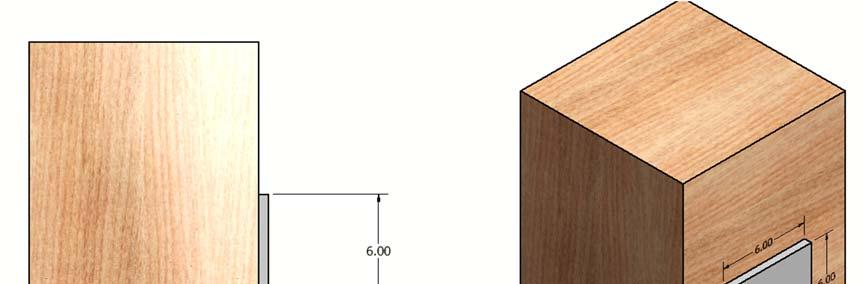
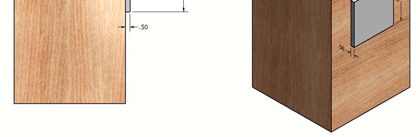
7 1000 lbs 1000 lbs 32. (20 points). If the previous 3/8 bolts are inserted into 3/8 holes, determine the bearing stress on the holes in the previous problem. 33. (15 points). A steel plate is fastened to a wooden block using (4) 3/8 diameter lag bolts that are embedded 2.5 into the wood, as shown. If a 5000-lb force is applied to the center of the steel plate, with orientation, as shown, determine the shear stress in a bolt lbs 34. (20 points). Considering the previous problem, determine the average shear stress between the lag bolts and the wood that the lag bolts are embedded in. Assume that all of the force transfer between the bolts and the wood occur in shear. 35. (20 points). A 6x6x½ steel plate is glued to a wooden block and subjected to an inclined force, P, determine the maximum force P that may be applied to the steel plate if the glue stresses must not exceed either 600 psi in shear or 1200 psi in tension.
8 4 3 P
9 ANSWERS TO QUESTIONS 1 TO 35 OF THIS GUIDE st, solve FBD ADB, then solve FBD BEC FALSE 6. FALSE external unknowns are solvable as one FBD, making it necessary to cut at internal pin to solve 2 separate FBD s kip-ft, compression on bottom kip-ft, compression on bottom kip-ft, compression on bottom kip-ft, compression on left 15. BC is a 2FM. Reaction is horizontal. Cy= FM: V= FM: M=0 18. TRUE 19. M=13.5 kip-ft (compression on top). V = 0.75 kips (positive) 20. N=250 lbs (T), V= lbs, M=1155 ft-lb (compression on left) 21. N=5kips, V=30/17 kips, M=180/17 kip-ft (compression on left) kip-ft, compression on bottom 23. FALSE 24. FALSE 25. TRUE 26. aa=2500psi (T), aa=0 27. aa=1600psi (T), aa=1200psi in ksi kips ksi ksi ksi psi kips (shear controls)
1 of 7. Law of Sines: Stress = E = G. Deformation due to Temperature: Δ
 NME: ES30 STRENGTH OF MTERILS FINL EXM: FRIDY, MY 1 TH 4PM TO 7PM Closed book. Calculator and writing supplies allowed. Protractor and compass allowed. 180 Minute Time Limit GIVEN FORMULE: Law of Cosines:
1 of 12. Law of Sines: Stress = E = G. Deformation due to Temperature: Δ
 NAME: ES30 STRENGTH OF MATERIALS FINAL EXAM: FRIDAY, MAY 1 TH 4PM TO 7PM Closed book. Calculator and writing supplies allowed. Protractor and compass allowed. 180 Minute Time Limit GIVEN FORMULAE: Law
Purpose of this Guide: To thoroughly prepare students for the exact types of problems that will be on Exam 3.
 ES230 STRENGTH OF MTERILS Exam 3 Study Guide Exam 3: Wednesday, March 8 th in-class Updated 3/3/17 Purpose of this Guide: To thoroughly prepare students for the exact types of problems that will be on
1 of 12. Given: Law of Cosines: C. Law of Sines: Stress = E = G
 ES230 STRENGTH OF MATERIALS FINAL EXAM: WEDNESDAY, MAY 15 TH, 4PM TO 7PM, AEC200 Closed book. Calculator and writing supplies allowed. Protractor and compass required. 180 Minute Time Limit You must have
ES226 (01) Engineering Mechanics: Statics Spring 2018 Lafayette College Engineering Division
 Engineering Mechanics: Statics Spring 2018 Lafayette College Engineering Division") ES226 (01) Engineering Mechanics: Statics Spring 2018 Lafayette College Engineering Division Exam 1 Study Guide Exam 1: Tuesday, February 6, 2018 7:30 to 8:30pm Kirby Room 104 Exam Format: 50 minute time
ES226 (01) Engineering Mechanics: Statics Spring 2018 Lafayette College Engineering Division Exam 1 Study Guide Exam 1: Tuesday, February 6, 2018 7:30 to 8:30pm Kirby Room 104 Exam Format: 50 minute time
MECHANICS OF MATERIALS. Prepared by Engr. John Paul Timola
 MECHANICS OF MATERIALS Prepared by Engr. John Paul Timola Mechanics of materials branch of mechanics that studies the internal effects of stress and strain in a solid body. stress is associated with the
If the solution does not follow a logical thought process, it will be assumed in error.
 Please indicate your group number (If applicable) Circle Your Instructor s Name and Section: MWF 8:30-9:20 AM Prof. Kai Ming Li MWF 2:30-3:20 PM Prof. Fabio Semperlotti MWF 9:30-10:20 AM Prof. Jim Jones
Final Exam - Spring
 EM121 Final Exam - Spring 2011-2012 Name : Section Number : Record all your answers to the multiple choice problems (1-15) by filling in the appropriate circle. All multiple choice answers will be graded
NAME: Given Formulae: Law of Cosines: Law of Sines:
 NME: Given Formulae: Law of Cosines: EXM 3 PST PROBLEMS (LESSONS 21 TO 28) 100 points Thursday, November 16, 2017, 7pm to 9:30, Room 200 You are allowed to use a calculator and drawing equipment, only.
Solution: The moment of inertia for the cross-section is: ANS: ANS: Problem 15.6 The material of the beam in Problem
 Problem 15.4 The beam consists of material with modulus of elasticity E 14x10 6 psi and is subjected to couples M 150, 000 in lb at its ends. (a) What is the resulting radius of curvature of the neutral
[5] Stress and Strain
![[5] Stress and Strain](/thumbs/95/123344550.jpg "[5] Stress and Strain") [5] Stress and Strain Page 1 of 34 [5] Stress and Strain [5.1] Internal Stress of Solids [5.2] Design of Simple Connections (will not be covered in class) [5.3] Deformation and Strain [5.4] Hooke s Law
[5] Stress and Strain Page 1 of 34 [5] Stress and Strain [5.1] Internal Stress of Solids [5.2] Design of Simple Connections (will not be covered in class) [5.3] Deformation and Strain [5.4] Hooke s Law
5. What is the moment of inertia about the x - x axis of the rectangular beam shown?
 1 of 5 Continuing Education Course #274 What Every Engineer Should Know About Structures Part D - Bending Strength Of Materials NOTE: The following question was revised on 15 August 2018 1. The moment
Determine the resultant internal loadings acting on the cross section at C of the beam shown in Fig. 1 4a.
 E X M P L E 1.1 Determine the resultant internal loadings acting on the cross section at of the beam shown in Fig. 1 a. 70 N/m m 6 m Fig. 1 Support Reactions. This problem can be solved in the most direct
This procedure covers the determination of the moment of inertia about the neutral axis.
 327 Sample Problems Problem 16.1 The moment of inertia about the neutral axis for the T-beam shown is most nearly (A) 36 in 4 (C) 236 in 4 (B) 136 in 4 (D) 736 in 4 This procedure covers the determination
Chapter 1 Introduction- Concept of Stress
 hapter 1 Introduction- oncept of Stress INTRODUTION Review of Statics xial Stress earing Stress Torsional Stress 14 6 ending Stress W W L Introduction 1-1 Shear Stress W W Stress and Strain L y y τ xy
MECE 3321: Mechanics of Solids Chapter 6
 MECE 3321: Mechanics of Solids Chapter 6 Samantha Ramirez Beams Beams are long straight members that carry loads perpendicular to their longitudinal axis Beams are classified by the way they are supported
Part 1 is to be completed without notes, beam tables or a calculator. DO NOT turn Part 2 over until you have completed and turned in Part 1.
 NAME CM 3505 Fall 06 Test 2 Part 1 is to be completed without notes, beam tables or a calculator. Part 2 is to be completed after turning in Part 1. DO NOT turn Part 2 over until you have completed and
ENGR-1100 Introduction to Engineering Analysis. Lecture 23
 ENGR-1100 Introduction to Engineering Analysis Lecture 23 Today s Objectives: Students will be able to: a) Draw the free body diagram of a frame and its members. FRAMES b) Determine the forces acting at
Stress Transformation Equations: u = +135 (Fig. a) s x = 80 MPa s y = 0 t xy = 45 MPa. we obtain, cos u + t xy sin 2u. s x = s x + s y.
 s x = 80 MPa s y = 0 t xy = 45 MPa. we obtain, cos u + t xy sin 2u. s x = s x + s y.") 014 Pearson Education, Inc., Upper Saddle River, NJ. All rights reserved. This material is protected under all copyright laws as they currently 9 7. Determine the normal stress and shear stress acting
014 Pearson Education, Inc., Upper Saddle River, NJ. All rights reserved. This material is protected under all copyright laws as they currently 9 7. Determine the normal stress and shear stress acting
READING QUIZ. 2. When using the method of joints, typically equations of equilibrium are applied at every joint. A) Two B) Three C) Four D) Six
 Two B) Three C) Four D) Six") READING QUIZ 1. One of the assumptions used when analyzing a simple truss is that the members are joined together by. A) Welding B) Bolting C) Riveting D) Smooth pins E) Super glue 2. When using the method
READING QUIZ 1. One of the assumptions used when analyzing a simple truss is that the members are joined together by. A) Welding B) Bolting C) Riveting D) Smooth pins E) Super glue 2. When using the method
Lecture 23. ENGR-1100 Introduction to Engineering Analysis FRAMES S 1
 ENGR-1100 Introduction to Engineering Analysis Lecture 23 Today s Objectives: Students will be able to: a) Draw the free body diagram of a frame and its members. FRAMES b) Determine the forces acting at
MECE 3321 MECHANICS OF SOLIDS CHAPTER 1
 MECE 3321 MECHANICS O SOLIDS CHAPTER 1 Samantha Ramirez, MSE WHAT IS MECHANICS O MATERIALS? Rigid Bodies Statics Dynamics Mechanics Deformable Bodies Solids/Mech. Of Materials luids 1 WHAT IS MECHANICS
and F NAME: ME rd Sample Final Exam PROBLEM 1 (25 points) Prob. 1 questions are all or nothing. PROBLEM 1A. (5 points)
 Prob. 1 questions are all or nothing. PROBLEM 1A. (5 points)") ME 270 3 rd Sample inal Exam PROBLEM 1 (25 points) Prob. 1 questions are all or nothing. PROBLEM 1A. (5 points) IND: In your own words, please state Newton s Laws: 1 st Law = 2 nd Law = 3 rd Law = PROBLEM
ME 270 3 rd Sample inal Exam PROBLEM 1 (25 points) Prob. 1 questions are all or nothing. PROBLEM 1A. (5 points) IND: In your own words, please state Newton s Laws: 1 st Law = 2 nd Law = 3 rd Law = PROBLEM
EQUATIONS OF EQUILIBRIUM & TWO- AND THREE-FORCE MEMEBERS
 EQUATIONS OF EQUILIBRIUM & TWO- AND THREE-FORCE MEMEBERS Today s Objectives: Students will be able to: a) Apply equations of equilibrium to solve for unknowns, and, b) Recognize two-force members. In-Class
Supplement: Statically Indeterminate Trusses and Frames
 : Statically Indeterminate Trusses and Frames Approximate Analysis - In this supplement, we consider an approximate method of solving statically indeterminate trusses and frames subjected to lateral loads
P.E. Civil Exam Review:
 P.E. Civil Exam Review: Structural Analysis J.P. Mohsen Email: jpm@louisville.edu Structures Determinate Indeterminate STATICALLY DETERMINATE STATICALLY INDETERMINATE Stability and Determinacy of Trusses
EQUATIONS OF EQUILIBRIUM & TWO-AND THREE-FORCE MEMEBERS
 EQUATIONS OF EQUILIBRIUM & TWO-AND THREE-FORCE MEMEBERS Today s Objectives: Students will be able to: a) Apply equations of equilibrium to solve for unknowns, and, b) Recognize two-force members. READING
6.6 FRAMES AND MACHINES APPLICATIONS. Frames are commonly used to support various external loads.
 6.6 FRAMES AND MACHINES APPLICATIONS Frames are commonly used to support various external loads. How is a frame different than a truss? How can you determine the forces at the joints and supports of a
Mechanics of Materials CIVL 3322 / MECH 3322
 Mechanics of Materials CIVL 3322 / MECH 3322 2 3 4 5 6 7 8 9 10 A Quiz 11 A Quiz 12 A Quiz 13 A Quiz 14 A Quiz 15 A Quiz 16 In Statics, we spent most of our time looking at reactions at supports Two variations
EQUATIONS OF EQUILIBRIUM & TWO- AND THREE-FORCE MEMBERS
 EQUATIONS OF EQUILIBRIUM & TWO- AND THREE-FORCE MEMBERS Today s Objectives: Students will be able to: a) Apply equations of equilibrium to solve for unknowns, and, b) Recognize two-force members. APPLICATIONS
Name (Print) ME Mechanics of Materials Exam # 2 Date: March 29, 2017 Time: 8:00 10:00 PM - Location: WTHR 200
 ME Mechanics of Materials Exam # 2 Date: March 29, 2017 Time: 8:00 10:00 PM - Location: WTHR 200") Name (Print) (Last) (First) Instructions: ME 323 - Mechanics of Materials Exam # 2 Date: Time: 8:00 10:00 PM - Location: WTHR 200 Circle your lecturer s name and your class meeting time. Koslowski Zhao
Name (Print) (Last) (First) Instructions: ME 323 - Mechanics of Materials Exam # 2 Date: Time: 8:00 10:00 PM - Location: WTHR 200 Circle your lecturer s name and your class meeting time. Koslowski Zhao
Chapter 7: Bending and Shear in Simple Beams
 Chapter 7: Bending and Shear in Simple Beams Introduction A beam is a long, slender structural member that resists loads that are generally applied transverse (perpendicular) to its longitudinal axis.
Continuing Education Course #207 What Every Engineer Should Know About Structures Part B Statics Applications
 1 of 6 Continuing Education Course #207 What Every Engineer Should Know About Structures Part B Statics Applications 1. As a practical matter, determining design loads on structural members involves several
Homework No. 1 MAE/CE 459/559 John A. Gilbert, Ph.D. Fall 2004
 Homework No. 1 MAE/CE 459/559 John A. Gilbert, Ph.D. 1. A beam is loaded as shown. The dimensions of the cross section appear in the insert. the figure. Draw a complete free body diagram showing an equivalent
Announcements. Trusses Method of Joints
 Announcements Mountain Dew is an herbal supplement Today s Objectives Define a simple truss Trusses Method of Joints Determine the forces in members of a simple truss Identify zero-force members Class
ARC 341 Structural Analysis II. Lecture 10: MM1.3 MM1.13
 ARC241 Structural Analysis I Lecture 10: MM1.3 MM1.13 MM1.4) Analysis and Design MM1.5) Axial Loading; Normal Stress MM1.6) Shearing Stress MM1.7) Bearing Stress in Connections MM1.9) Method of Problem
Timber and Steel Design. Lecture 11. Bolted Connections
 Timber and Steel Design Lecture 11 Bolted Connections Riveted Connections Types of Joints Failure of Joints Bearing & Friction connections Truss Joints Shear and Tension on Bolt S U R A N A R E E UNIVERSITY
MAAE 2202 A. Come to the PASS workshop with your mock exam complete. During the workshop you can work with other students to review your work.
 It is most beneficial to you to write this mock final exam UNDER EXAM CONDITIONS. This means: Complete the exam in 3 hours. Work on your own. Keep your textbook closed. Attempt every question. After the
Shear Forces And Bending Moments
 Shear Forces And Bending Moments 1 Introduction 2001 Brooks/Cole, a division of Thomson Learning, Inc. Thomson Learning is a trademark used herein under license. Fig. 4-1 Examples of beams subjected to
ME 202 STRENGTH OF MATERIALS SPRING 2014 HOMEWORK 4 SOLUTIONS
 ÇANKAYA UNIVERSITY MECHANICAL ENGINEERING DEPARTMENT ME 202 STRENGTH OF MATERIALS SPRING 2014 Due Date: 1 ST Lecture Hour of Week 12 (02 May 2014) Quiz Date: 3 rd Lecture Hour of Week 12 (08 May 2014)
Tension Members. ENCE 455 Design of Steel Structures. II. Tension Members. Introduction. Introduction (cont.)
") ENCE 455 Design of Steel Structures II. Tension Members C. C. Fu, Ph.D., P.E. Civil and Environmental Engineering Department University of Maryland Tension Members Following subjects are covered: Introduction
ENCE 455 Design of Steel Structures II. Tension Members C. C. Fu, Ph.D., P.E. Civil and Environmental Engineering Department University of Maryland Tension Members Following subjects are covered: Introduction
Lecture 20. ENGR-1100 Introduction to Engineering Analysis THE METHOD OF SECTIONS
 ENGR-1100 Introduction to Engineering Analysis Lecture 20 THE METHOD OF SECTIONS Today s Objectives: Students will be able to determine: 1. Forces in truss members using the method of sections. In-Class
ENGR-1100 Introduction to Engineering Analysis. Lecture 20
 ENGR-1100 Introduction to Engineering Analysis Lecture 20 Today s Objectives: THE METHOD OF SECTIONS Students will be able to determine: 1. Forces in truss members using the method of sections. In-Class
Shear Force and Bending Moment Diagrams for a Beam Steven Vukazich San Jose State University
 Shear Force and Bending oment Diagrams for a Beam Steven ukazich San Jose State University General procedure for the construction of internal force diagrams 1. Find all of the eternal forces and draw the
The centroid of an area is defined as the point at which (12-2) The distance from the centroid of a given area to a specified axis may be found by
 The distance from the centroid of a given area to a specified axis may be found by") Unit 12 Centroids Page 12-1 The centroid of an area is defined as the point at which (12-2) The distance from the centroid of a given area to a specified axis may be found by (12-5) For the area shown
Unit 12 Centroids Page 12-1 The centroid of an area is defined as the point at which (12-2) The distance from the centroid of a given area to a specified axis may be found by (12-5) For the area shown
7 STATICALLY DETERMINATE PLANE TRUSSES
 7 STATICALLY DETERMINATE PLANE TRUSSES OBJECTIVES: This chapter starts with the definition of a truss and briefly explains various types of plane truss. The determinancy and stability of a truss also will
Problem d d d B C E D. 0.8d. Additional lecturebook examples 29 ME 323
 Problem 9.1 Two beam segments, AC and CD, are connected together at C by a frictionless pin. Segment CD is cantilevered from a rigid support at D, and segment AC has a roller support at A. a) Determine
Please review the following statement: I certify that I have not given unauthorized aid nor have I received aid in the completion of this exam.
 Please review the followg statement: I certify that I have not given unauthorized aid nor have I received aid the completion of this eam. Signature: INSTRUCTIONS Beg each problem the space provided on
Chapter 6: Structural Analysis
 Chapter 6: Structural Analysis Chapter Objectives To show how to determine the forces in the members of a truss using the method of joints and the method of sections. To analyze the forces acting on the
SRSD 2093: Engineering Mechanics 2SRRI SECTION 19 ROOM 7, LEVEL 14, MENARA RAZAK
 SRSD 2093: Engineering Mechanics 2SRRI SECTION 19 ROOM 7, LEVEL 14, MENARA RAZAK SIMPLE TRUSSES, THE METHOD OF JOINTS, & ZERO-FORCE MEMBERS Today s Objectives: Students will be able to: a) Define a simple
Symmetric Bending of Beams
 Symmetric Bending of Beams beam is any long structural member on which loads act perpendicular to the longitudinal axis. Learning objectives Understand the theory, its limitations and its applications
Homework 6.1 P = 1000 N. δ δ δ. 4 cm 4 cm 4 cm. 10 cm
 Homework 6.1 Three thick and wide boards are connected together by two parallel rows of uniformly distributed nails separated by longitude distance δ to form a beam that is subject to constant vertical
Example: 5-panel parallel-chord truss. 8 ft. 5 k 5 k 5 k 5 k. F yield = 36 ksi F tension = 21 ksi F comp. = 10 ksi. 6 ft.
 CE 331, Spring 2004 Beam Analogy for Designing Trusses 1 / 9 We need to make several decisions in designing trusses. First, we need to choose a truss. Then we need to determine the height of the truss
Design of Reinforced Concrete Beam for Shear
 Lecture 06 Design of Reinforced Concrete Beam for Shear By: Civil Engineering Department UET Peshawar drqaisarali@uetpeshawar.edu.pk Topics Addressed Shear Stresses in Rectangular Beams Diagonal Tension
Engineering Mechanics: Statics STRUCTURAL ANALYSIS. by Dr. Ibrahim A. Assakkaf SPRING 2007 ENES 110 Statics
 CHAPTER Engineering Mechanics: Statics STRUCTURAL ANALYSIS College of Engineering Department of Mechanical Engineering Tenth Edition 6a by Dr. Ibrahim A. Assakkaf SPRING 2007 ENES 110 Statics Department
Sample Questions for the ME328 Machine Design Final Examination Closed notes, closed book, no calculator.
 Sample Questions for the ME328 Machine Design Final Examination Closed notes, closed book, no calculator. The following is from the first page of the examination. I recommend you read it before the exam.
The University of Melbourne Engineering Mechanics
 The University of Melbourne 436-291 Engineering Mechanics Tutorial Four Poisson s Ratio and Axial Loading Part A (Introductory) 1. (Problem 9-22 from Hibbeler - Statics and Mechanics of Materials) A short
Engineering Mechanics Department of Mechanical Engineering Dr. G. Saravana Kumar Indian Institute of Technology, Guwahati
 Engineering Mechanics Department of Mechanical Engineering Dr. G. Saravana Kumar Indian Institute of Technology, Guwahati Module 3 Lecture 6 Internal Forces Today, we will see analysis of structures part
Solid Mechanics Homework Answers
 Name: Date: Solid Mechanics Homework nswers Please show all of your work, including which equations you are using, and circle your final answer. Be sure to include the units in your answers. 1. The yield
UNIVERSITY OF SASKATCHEWAN ME MECHANICS OF MATERIALS I FINAL EXAM DECEMBER 13, 2008 Professor A. Dolovich
 UNIVERSITY OF SASKATCHEWAN ME 313.3 MECHANICS OF MATERIALS I FINAL EXAM DECEMBER 13, 2008 Professor A. Dolovich A CLOSED BOOK EXAMINATION TIME: 3 HOURS For Marker s Use Only LAST NAME (printed): FIRST
ENGR-1100 Introduction to Engineering Analysis. Lecture 19
 ENGR-1100 Introduction to Engineering Analysis Lecture 19 SIMPLE TRUSSES, THE METHOD OF JOINTS, & ZERO-FORCE MEMBERS Today s Objectives: Students will be able to: In-Class Activities: a) Define a simple
Laith Batarseh. internal forces
 Next Previous 1/8/2016 Chapter seven Laith Batarseh Home End Definitions When a member is subjected to external load, an and/or moment are generated inside this member. The value of the generated internal
OUT ON A LIMB AND HUNG OUT TO DRY :
 27-Nov-12 17:03 1 of 2 h p://edugen.wileyplus.com/edugen/courses/crs1404/pc/c10/c2hlchbhcmq3mjewyzewxzeuegzvcm0.enc?course=crs1404&id=ref CHAPTER 10 OUT ON A LIMB AND HUNG OUT TO DRY : A LOOK AT INTERNAL
You must have a compass, ruler, and protractor for this exam
 ES30 STRENGTH OF MATERIALS FINAL EXAM: WEDNESDAY, MAY 14 TH, 4PM TO 7PM, HUGEL 100 Closed book. Calculator and writing supplies allowed. Protractor and compass required. 180 Minute Time Limit Given: Law
Samantha Ramirez, MSE. Stress. The intensity of the internal force acting on a specific plane (area) passing through a point. F 2
 passing through a point. F 2") Samantha Ramirez, MSE Stress The intensity of the internal force acting on a specific plane (area) passing through a point. Δ ΔA Δ z Δ 1 2 ΔA Δ x Δ y ΔA is an infinitesimal size area with a uniform force
Samantha Ramirez, MSE Stress The intensity of the internal force acting on a specific plane (area) passing through a point. Δ ΔA Δ z Δ 1 2 ΔA Δ x Δ y ΔA is an infinitesimal size area with a uniform force
2. Rigid bar ABC supports a weight of W = 50 kn. Bar ABC is pinned at A and supported at B by rod (1). What is the axial force in rod (1)?
. What is the axial force in rod (1)?") IDE 110 S08 Test 1 Name: 1. Determine the internal axial forces in segments (1), (2) and (3). (a) N 1 = kn (b) N 2 = kn (c) N 3 = kn 2. Rigid bar ABC supports a weight of W = 50 kn. Bar ABC is pinned at
IDE 110 S08 Test 1 Name: 1. Determine the internal axial forces in segments (1), (2) and (3). (a) N 1 = kn (b) N 2 = kn (c) N 3 = kn 2. Rigid bar ABC supports a weight of W = 50 kn. Bar ABC is pinned at
COLUMNS: BUCKLING (DIFFERENT ENDS)
") COLUMNS: BUCKLING (DIFFERENT ENDS) Buckling of Long Straight Columns Example 4 Slide No. 1 A simple pin-connected truss is loaded and supported as shown in Fig. 1. All members of the truss are WT10 43
COLUMNS: BUCKLING (DIFFERENT ENDS) Buckling of Long Straight Columns Example 4 Slide No. 1 A simple pin-connected truss is loaded and supported as shown in Fig. 1. All members of the truss are WT10 43
I certify that I have not given unauthorized aid nor have I received aid in the completion of this exam.
 Examination No. 2 Please review the following statement: Group Number: I certify that I have not given unauthorized aid nor have I received aid in the completion of this exam. Signature: INSTRUCTIONS Begin
Calculating Truss Forces. Method of Joints
 Calculating Truss Forces Method of Joints Forces Compression body being squeezed Tension body being stretched Truss truss is composed of slender members joined together at their end points. They are usually
OUTCOME 1 - TUTORIAL 3 BENDING MOMENTS. You should judge your progress by completing the self assessment exercises. CONTENTS
 Unit 2: Unit code: QCF Level: 4 Credit value: 15 Engineering Science L/601/1404 OUTCOME 1 - TUTORIAL 3 BENDING MOMENTS 1. Be able to determine the behavioural characteristics of elements of static engineering
By Dr. Mohammed Ramidh
 Engineering Materials Design Lecture.6 the design of beams By Dr. Mohammed Ramidh 6.1 INTRODUCTION Finding the shear forces and bending moments is an essential step in the design of any beam. we usually
Chapter 6: Structural Analysis
 Chapter 6: Structural Analysis APPLICATIONS Trusses are commonly used to support a roof. For a given truss geometry and load, how can we determine the forces in the truss members and select their sizes?
IDE 110 Mechanics of Materials Spring 2006 Final Examination FOR GRADING ONLY
 Spring 2006 Final Examination STUDENT S NAME (please print) STUDENT S SIGNATURE STUDENT NUMBER IDE 110 CLASS SECTION INSTRUCTOR S NAME Do not turn this page until instructed to start. Write your name on
EQUATIONS OF EQUILIBRIUM & TWO- AND THREE-FORCE MEMBERS
 EQUATIONS OF EQUILIBRIUM & TWO- AND THREE-FORCE MEMBERS Today s Objectives: Students will be able to: a) Apply equations of equilibrium to solve for unknowns b) Identify support reactions c) Recognize
Supplement: Statically Indeterminate Frames
 : Statically Indeterminate Frames Approximate Analysis - In this supplement, we consider another approximate method of solving statically indeterminate frames subjected to lateral loads known as the. Like
Section Downloads. Section Downloads. Handouts & Slides can be printed. Course binders are available for purchase. Download & Print. Version 2.
 Level II: Section 03 Design Principles Section Downloads 2 Section Downloads Handouts & Slides can be printed Version 2.0 Course binders are available for purchase Not required Download & Print TTT II
Entrance exam Master Course
 - 1 - Guidelines for completion of test: On each page, fill in your name and your application code Each question has four answers while only one answer is correct. o Marked correct answer means 4 points
EMA 3702 Mechanics & Materials Science (Mechanics of Materials) Chapter 2 Stress & Strain - Axial Loading
 Chapter 2 Stress & Strain - Axial Loading") MA 3702 Mechanics & Materials Science (Mechanics of Materials) Chapter 2 Stress & Strain - Axial Loading MA 3702 Mechanics & Materials Science Zhe Cheng (2018) 2 Stress & Strain - Axial Loading Statics
MA 3702 Mechanics & Materials Science (Mechanics of Materials) Chapter 2 Stress & Strain - Axial Loading MA 3702 Mechanics & Materials Science Zhe Cheng (2018) 2 Stress & Strain - Axial Loading Statics
Name. ME 270 Fall 2005 Final Exam PROBLEM NO. 1. Given: A distributed load is applied to the top link which is, in turn, supported by link AC.
 Name ME 270 Fall 2005 Final Exam PROBLEM NO. 1 Given: A distributed load is applied to the top link which is, in turn, supported by link AC. Find: a) Draw a free body diagram of link BCDE and one of link
ME Statics. Structures. Chapter 4
 ME 108 - Statics Structures Chapter 4 Outline Applications Simple truss Method of joints Method of section Germany Tacoma Narrows Bridge http://video.google.com/videoplay?docid=-323172185412005564&q=bruce+lee&pl=true
Free Body Diagram: Solution: The maximum load which can be safely supported by EACH of the support members is: ANS: A =0.217 in 2
 Problem 10.9 The angle β of the system in Problem 10.8 is 60. The bars are made of a material that will safely support a tensile normal stress of 8 ksi. Based on this criterion, if you want to design the
Announcements. Equilibrium of a Rigid Body
 Announcements Equilibrium of a Rigid Body Today s Objectives Identify support reactions Draw a free body diagram Class Activities Applications Support reactions Free body diagrams Examples Engr221 Chapter
8.1 Internal Forces in Structural Members
 8.1 Internal Forces in Structural Members 8.1 Internal Forces in Structural Members xample 1, page 1 of 4 1. etermine the normal force, shear force, and moment at sections passing through a) and b). 4
I certify that I have not given unauthorized aid nor have I received aid in the completion of this exam.
 NAME: ME 270 Fall 2012 Examination No. 3 - Makeup Please review the following statement: Group No.: I certify that I have not given unauthorized aid nor have I received aid in the completion of this exam.
INTERNAL FORCES Today s Objective: Students will be able to: 1. Use the method of sections for determining internal forces in 2-D load cases.
 INTERNAL FORCES Today s Objective: Students will be able to: 1. Use the method of sections for determining internal forces in 2-D load cases. In-Class Activities: Check Homework, if any Reading Quiz Applications
REVIEW. Final Exam. Final Exam Information. Final Exam Information. Strategy for Studying. Test taking strategy. Sign Convention Rules
 Final Exam Information REVIEW Final Exam (Print notes) DATE: WEDNESDAY, MAY 12 TIME: 1:30 PM - 3:30 PM ROOM ASSIGNMENT: Toomey Hall Room 199 1 2 Final Exam Information Comprehensive exam covers all topics
Chapter 7 INTERNAL FORCES
 Chapter 7 INTERNAL FORCES READING QUIZ 1. In a multiforce member, the member is generally subjected to an internal. A) normal force B) shear force C) bending moment D) All of the above. 2. In mechanics,
Statics Chapter II Fall 2018 Exercises Corresponding to Sections 2.1, 2.2, and 2.3
 Statics Chapter II Fall 2018 Exercises Corresponding to Sections 2.1, 2.2, and 2.3 2 3 Determine the magnitude of the resultant force FR = F1 + F2 and its direction, measured counterclockwise from the
STRESS. Bar. ! Stress. ! Average Normal Stress in an Axially Loaded. ! Average Shear Stress. ! Allowable Stress. ! Design of Simple Connections
 STRESS! Stress Evisdom! verage Normal Stress in an xially Loaded ar! verage Shear Stress! llowable Stress! Design of Simple onnections 1 Equilibrium of a Deformable ody ody Force w F R x w(s). D s y Support
Design of Reinforced Concrete Beam for Shear
 Lecture 06 Design of Reinforced Concrete Beam for Shear By: Prof Dr. Qaisar Ali Civil Engineering Department UET Peshawar drqaisarali@uetpeshawar.edu.pk 1 Topics Addressed Shear Stresses in Rectangular
Solid Mechanics Chapter 1: Tension, Compression and Shear
 Solid Mechanics Chapter 1: Tension, Compression and Shear Dr. Imran Latif Department of Civil and Environmental Engineering College of Engineering University of Nizwa (UoN) 1 Why do we study Mechanics
BE Semester- I ( ) Question Bank (MECHANICS OF SOLIDS)
 Question Bank (MECHANICS OF SOLIDS)") BE Semester- I ( ) Question Bank (MECHANICS OF SOLIDS) All questions carry equal marks(10 marks) Q.1 (a) Write the SI units of following quantities and also mention whether it is scalar or vector: (i)
BE Semester- I ( ) Question Bank (MECHANICS OF SOLIDS) All questions carry equal marks(10 marks) Q.1 (a) Write the SI units of following quantities and also mention whether it is scalar or vector: (i)
CH. 5 TRUSSES BASIC PRINCIPLES TRUSS ANALYSIS. Typical depth-to-span ratios range from 1:10 to 1:20. First: determine loads in various members
 CH. 5 TRUSSES BASIC PRINCIPLES Typical depth-to-span ratios range from 1:10 to 1:20 - Flat trusses require less overall depth than pitched trusses Spans: 40-200 Spacing: 10 to 40 on center - Residential
Properties of Sections
 ARCH 314 Structures I Test Primer Questions Dr.-Ing. Peter von Buelow Properties of Sections 1. Select all that apply to the characteristics of the Center of Gravity: A) 1. The point about which the body
CONNECTION DESIGN. Connections must be designed at the strength limit state
 CONNECTION DESIGN Connections must be designed at the strength limit state Average of the factored force effect at the connection and the force effect in the member at the same point At least 75% of the
Mechanical Properties of Materials
 Mechanical Properties of Materials Strains Material Model Stresses Learning objectives Understand the qualitative and quantitative description of mechanical properties of materials. Learn the logic of
ENGR-1100 Introduction to Engineering Analysis. Lecture 13
 ENGR-1100 Introduction to Engineering Analysis Lecture 13 EQUILIBRIUM OF A RIGID BODY & FREE-BODY DIAGRAMS Today s Objectives: Students will be able to: a) Identify support reactions, and, b) Draw a free-body
ME Final Exam. PROBLEM NO. 4 Part A (2 points max.) M (x) y. z (neutral axis) beam cross-sec+on. 20 kip ft. 0.2 ft. 10 ft. 0.1 ft.
 M (x) y. z (neutral axis) beam cross-sec+on. 20 kip ft. 0.2 ft. 10 ft. 0.1 ft.") ME 323 - Final Exam Name December 15, 2015 Instructor (circle) PROEM NO. 4 Part A (2 points max.) Krousgrill 11:30AM-12:20PM Ghosh 2:30-3:20PM Gonzalez 12:30-1:20PM Zhao 4:30-5:20PM M (x) y 20 kip ft 0.2
ME 323 - Final Exam Name December 15, 2015 Instructor (circle) PROEM NO. 4 Part A (2 points max.) Krousgrill 11:30AM-12:20PM Ghosh 2:30-3:20PM Gonzalez 12:30-1:20PM Zhao 4:30-5:20PM M (x) y 20 kip ft 0.2
Section Downloads. Design Process. Design Principles Outline. Basic Design Principles. Design Process. Section 06: Design Principles.
 Section Downloads Section 06: Design Principles 1 Download & Print TTT I Sec 06 Slides TTT I Sec 06 Handout Section 05 Truss Materials Design Values PS 20 Section 01 TPI 1-2007 Selection 6.4.2 Repetitive
ME 323 MIDTERM # 1: SOLUTION FALL SEMESTER Time allowed: 1hour
 Instructions ME 2 MIDTERM # : SOLUTION FALL SEMESTER 20 Time allowed: hour. Begin each problem in the space provided on the examination sheets. If additional space is required, use the yellow paper provided.