mith College Computer Science CSC270 Spring 16 Circuits and Systems Lecture Notes Week 3 Dominique Thiébaut
|
|
|
- Kevin Stokes
- 5 years ago
- Views:
Transcription
1 mith College Computer Science CSC270 Spring 16 Circuits and Systems Lecture Notes Week 3 Dominique Thiébaut dthiebaut@smith.edu
2 Crash Course in Electricity and Electronics


3 Zero Physics background expected!
4 Hydrodynamic Analogy Outline Resistance, Intensity, Difference in Potentials Ohm's Law Exercises: solving electrical circuits Resistors Diode Transistor Practical Circuits
5 Main Concepts: Difference in Potentials vs. Intensity
6 An Analogy Hoover Dam
7 An Analogy Hoover Dam Difference in Potentials Intensity
8 An Analogy Hoover Dam Difference in Potentials Resistance Intensity
9 An Analogy Hoover Dam Difference Resistance in Potentials Intensity =0

10 An Analogy Hoover Dam Difference in Potentials Intensity
11 Hydrodynamic Analogy Outline Resistance, Intensity, Difference in Potentials Ohm's Law Exercises: solving electrical circuits Resistors Diode Transistor Practical Circuits
12 Observations Resistance Intensity Resistance oo x Intensity 0 High difference in potentials Intensity Low difference in potentials Intensity
13 Observations Resistance Intensity Resistance oo x Intensity 0 High difference in potentials Intensity Low difference in potentials Intensity
14 Observations Resistance Intensity Resistance oo x Intensity 0 High difference in potentials Intensity Low difference in potentials Intensity
15 Observations Resistance Intensity Resistance oo x Intensity 0 High difference in potentials Intensity Low difference in potentials Intensity
16 Observations Resistance Intensity Resistance oo x Intensity 0 High difference in potentials Intensity Low difference in potentials Intensity
17 Another Analogy
18 Another Analogy Difference in Pressure
19 Another Analogy Difference in Pressure No resistance in the pipe no difference in pressure
20 Another Analogy Resistance Difference in Pressure
21 Another Analogy Resistance Difference in Pressure
22 Observations Keeping Intensity constant, Resistance Difference in Potentials
23 + - R
24 + - R
25 I current Power Supply + - V voltage R Resistance Ground
26 Assumptions An electrical wire has no resistance A closed switch has no resistance An open switch has infinite resistance The current flowing in a closed-loop circuit is the same everywhere.
27 I current Power Supply + - V voltage R Resistance Ground
28 Hydrodynamic Analogy Outline Resistance, Intensity, Difference in Potentials Ohm's Law Exercises: solving electrical circuits Resistors Diode Transistor Practical Circuits
29 Ohm s Law Voltage = Resistance * Intensity V = R. I
30 Ohm s Law Voltage = Resistance * Intensity V = R. I Volt Ohm Amp V Ω A
31 Hydrodynamic Analogy Outline Resistance, Intensity, Difference in Potentials Ohm's Law Exercises: solving electrical circuits Resistors Diode Transistor Practical Circuits
32 What is I? I 5V + - V voltage R 1 KΩ Ground
33 What are I, I1, I2? I 5V + - I2 R2 1 KΩ I1 R1 1 KΩ Ground
34 What is I? 5V + - I R1 1 KΩ R2 4 KΩ Ground
35 What are V1, V2? 5V + I V1 R1 1 KΩ - V2 R2 4 KΩ Ground
36 What are V1, V2? 5V + I V1 R1 1 KΩ - V2 R2 4 KΩ Ground

37 What is I? 5V + - R1 3 KΩ R2 7 KΩ I Ground
38 Hydrodynamic Analogy Outline Resistance, Intensity, Difference in Potentials Ohm's Law Exercises: solving electrical circuits Resistors Diode Transistor Practical Circuits
39 What does R look like?
40
41 What values?
42 Simplification I 5V + - V voltage R 1 KΩ Ground
43 Simplification +5V R 1 KΩ
44 How Does that Apply to Us? 1 x
45 How Does that Apply to Us? +5V 1 x x

46 We stopped here last time
47 How Does that Apply to Us? x 0
48 How Does that Apply to Us? x 0 x 0
?")
49 Exercise +5V 2-to-4 A1 Y0' Y What is Y(a)? a A0 Y1' NC Y2' NC E' Y3' NC
50 Hydrodynamic Analogy Outline Resistance, Intensity, Difference in Potentials Ohm's Law Exercises: solving electrical circuits Resistors Diode Transistor Practical Circuits

51 Meet The Diode
52 Diode = semiconductor
53 R1 1 KΩ + - P N
54 R1 1 KΩ + - P N
55 R1 1 KΩ + - N P
56 R1 1 KΩ + - N P
57 Symbol R1 1 KΩ + - P N
58 Hydrodynamic Analogy Outline Resistance, Intensity, Difference in Potentials Ohm's Law Exercises: solving electrical circuits Resistors Diode Transistor Practical Circuits
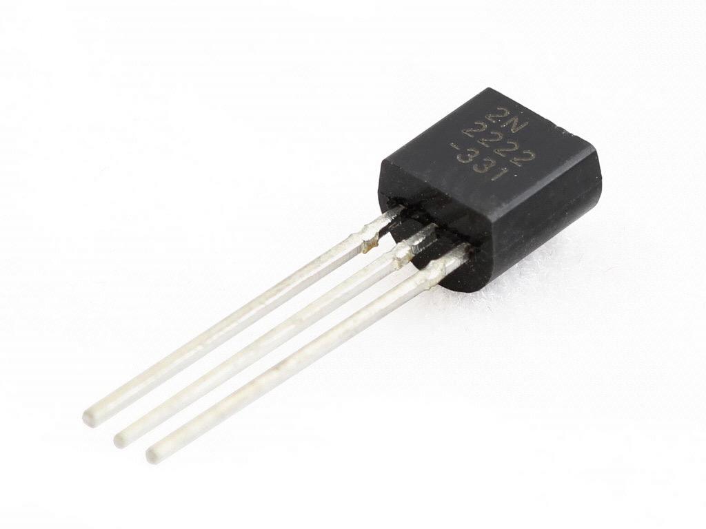
59 Meet the Transistor
60 R1 1 KΩ C + - N P N B R2 10 KΩ + - E Collector Base Emitter
61 R1 1 KΩ C + - N P N B R2 10 KΩ V E Collector Base Emitter
62 R1 1 KΩ C + - N P N B R2 10 KΩ + - E Collector Base Emitter
63 R1 1 KΩ C + - N P N B R2 10 KΩ V E Collector Base Emitter
64 Symbol R1 1 KΩ + C B R2 - E 10 KΩ + - Collector Base Emitter
65 Symbol R1 1 KΩ + C B R2 - E 10 KΩ + - Collector Base Emitter
66 What is f(a)? Quiz 1 KΩ a KΩ f 2N2222
67 A Real TTL Circuit

68 A Real TTL Circuit
69 A Real TTL Circuit

70 A Real TTL Circuit

71 What is h(a,b)? Quiz 1 KΩ 1 KΩ a b 10 KΩ 10 KΩ h
72 Hydrodynamic Analogy Outline Resistance, Intensity, Difference in Potentials Ohm's Law Exercises: solving electrical circuits Resistors Diode Transistor Practical Circuits
73 Practical Design Rules for Discrete Parts

74 Input Switch 1 KΩ
75 Logic Indicator R 04

76 Logic Indicator What s a good value? R 04
77 Logic Indicator What s a good value? R 04
mith College Computer Science CSC270 Spring 16 Circuits and Systems Lecture Notes Week 2 Dominique Thiébaut
 mith College Computer Science CSC270 Spring 16 Circuits and Systems Lecture Notes Week 2 Dominique Thiébaut dthiebaut@smith.edu Lab 1: Lessons Learned a0 b0 adder c0 S0 a1 b1 a0 b0 adder adder S1 S0 a31
As light level increases, resistance decreases. As temperature increases, resistance decreases. Voltage across capacitor increases with time LDR
 LDR As light level increases, resistance decreases thermistor As temperature increases, resistance decreases capacitor Voltage across capacitor increases with time Potential divider basics: R 1 1. Both
They keep the voltage the same and use this circuit to measure the current. Variable resistor. Reading on ammeter in amps
 1 Ksenia and Eva investigate five different variable resistors. They set each variable resistor to the maximum resistance. They keep the voltage the same and use this circuit to measure the current. A
A.M. WEDNESDAY, 13 May minutes
 Candidate Name Centre Number Candidate Number 0 GCSE 293/02 ELECTRONICS MODULE TEST E1 HIGHER TIER AM WEDNESDAY, 13 May 2009 45 minutes For Examiner s use Total Mark ADDITIONAL MATERIALS In addition to
Outline. Week 5: Circuits. Course Notes: 3.5. Goals: Use linear algebra to determine voltage drops and branch currents.
 Outline Week 5: Circuits Course Notes: 3.5 Goals: Use linear algebra to determine voltage drops and branch currents. Components in Resistor Networks voltage source current source resistor Components in
Chapter 2. Engr228 Circuit Analysis. Dr Curtis Nelson
 Chapter 2 Engr228 Circuit Analysis Dr Curtis Nelson Chapter 2 Objectives Understand symbols and behavior of the following circuit elements: Independent voltage and current sources; Dependent voltage and
SOME USEFUL NETWORK THEOREMS
 APPENDIX D SOME USEFUL NETWORK THEOREMS Introduction In this appendix we review three network theorems that are useful in simplifying the analysis of electronic circuits: Thévenin s theorem Norton s theorem
What to Add Next time you update?
 What to Add Next time you update? Work sheet with 3 and 4 resistors Create worksheet of tables Add Hypothesis and Questions Add Lab and Lecture Objectives Add equipment needed Add science standards Review
Chapter 21 Electric Current and Circuits
 Chapter 21 Electric Current and Circuits 1 As an introduction to this chapter you should view the following movie. If you cannot click on the link, then copy it and paste it into your web browser. http://www.ionaphysics.org/movies/vir.mp4
Simultaneous equations for circuit analysis
 Simultaneous equations for circuit analysis This worksheet and all related files are licensed under the Creative Commons Attribution License, version 1.0. To view a copy of this license, visit http://creativecommons.org/licenses/by/1.0/,
Parallel Resistors (32.6)
") Parallel Resistors (32.6) Resistors connected at both ends are called parallel resistors The important thing to note is that: the two left ends of the resistors are at the same potential. Also, the two
Parallel Resistors (32.6) Resistors connected at both ends are called parallel resistors The important thing to note is that: the two left ends of the resistors are at the same potential. Also, the two
resistance in the circuit. When voltage and current values are known, apply Ohm s law to determine circuit resistance. R = E/I ( )
") DC Fundamentals Ohm s Law Exercise 1: Ohm s Law Circuit Resistance EXERCISE OBJECTIVE When you have completed this exercise, you will be able to determine resistance by using Ohm s law. You will verify
DC Fundamentals Ohm s Law Exercise 1: Ohm s Law Circuit Resistance EXERCISE OBJECTIVE When you have completed this exercise, you will be able to determine resistance by using Ohm s law. You will verify
Parallel Resistors (32.6)
") Parallel Resistors (32.6) Resistors connected at both ends are called parallel resistors Neil Alberding (SFU Physics) Physics 121: Optics, Electricity & Magnetism Spring 2010 1 / 1 Parallel Resistors (32.6)
Parallel Resistors (32.6) Resistors connected at both ends are called parallel resistors Neil Alberding (SFU Physics) Physics 121: Optics, Electricity & Magnetism Spring 2010 1 / 1 Parallel Resistors (32.6)
Ohm's Law and Resistance
 Ohm's Law and Resistance Resistance Resistance is the property of a component which restricts the flow of electric current. Energy is used up as the voltage across the component drives the current through
Greek Letter Omega Ω = Ohm (Volts per Ampere)
") ) What is electric current? Flow of Electric Charge 2) What is the unit we use for electric current? Amperes (Coulombs per Second) 3) What is electrical resistance? Resistance to Electric Current 4) What
) What is electric current? Flow of Electric Charge 2) What is the unit we use for electric current? Amperes (Coulombs per Second) 3) What is electrical resistance? Resistance to Electric Current 4) What
4.2.1 Current, potential difference and resistance
 4.2 Electricity Electric charge is a fundamental property of matter everywhere. Understanding the difference in the microstructure of conductors, semiconductors and insulators makes it possible to design
Notes on Electricity (Circuits)
") A circuit is defined to be a collection of energy-givers (batteries) and energy-takers (resistors, light bulbs, radios, etc.) that form a closed path (or complete path) through which electrical current
A circuit is defined to be a collection of energy-givers (batteries) and energy-takers (resistors, light bulbs, radios, etc.) that form a closed path (or complete path) through which electrical current
Lecture #3. Review: Power
 Lecture #3 OUTLINE Power calculations Circuit elements Voltage and current sources Electrical resistance (Ohm s law) Kirchhoff s laws Reading Chapter 2 Lecture 3, Slide 1 Review: Power If an element is
Kirchhoff's Laws and Circuit Analysis (EC 2)
") Kirchhoff's Laws and Circuit Analysis (EC ) Circuit analysis: solving for I and V at each element Linear circuits: involve resistors, capacitors, inductors Initial analysis uses only resistors Power sources,
Kirchhoff's Laws and Circuit Analysis (EC ) Circuit analysis: solving for I and V at each element Linear circuits: involve resistors, capacitors, inductors Initial analysis uses only resistors Power sources,
Industrial Technology: Electronic Technology Crosswalk to AZ Math Standards
 Page 1 of 1 August 1998 1M-P1 Compare and contrast the real number system and its various subsystems with regard to their structural characteristics. PO 2 PO 3 2.0 Apply mathematics calculations. 2.1 Apply
CS 436 HCI Technology Basic Electricity/Electronics Review
 CS 436 HCI Technology Basic Electricity/Electronics Review *Copyright 1997-2008, Perry R. Cook, Princeton University August 27, 2008 1 Basic Quantities and Units 1.1 Charge Number of electrons or units
4.2.1 Current, potential difference and resistance Standard circuit diagram symbols. Content. Key opportunities for skills development WS 1.
 4.2 Electricity Electric charge is a fundamental property of matter everywhere. Understanding the difference in the microstructure of conductors, semiconductors and insulators makes it possible to design
Ohm s Law and Electronic Circuits
 Production Ohm s Law and Electronic Circuits Page 1 - Cyber Security Class ELECTRICAL CIRCUITS All you need to be an inventor is a good imagination and a pile of junk. -Thomas Edison Page 2 - Cyber Security
STEAM Clown Production. Series Circuits. STEAM Clown & Productions Copyright 2017 STEAM Clown. Page 2
 Production Series Circuits Page 2 Copyright 2017 Series Parallel Circuits + + SERIES CIRCUIT PARALLEL CIRCUIT Page 3 Copyright 2017 Trick to Remember Ohm s Law V V=I*R R = V I I R I = V R Page 4 Copyright
Unit 2 Electrical Quantities and Ohm s Law
 Electrical Quantities and Ohm s Law Objectives: Define a coulomb. Define an ampere. Define a volt. Define an ohm. Define a watt. Objectives: Compute electrical values using Ohm s law. Discuss basic types
5. ELECTRIC CURRENTS
 5. ELECTRIC CURRENTS TOPIC OUTLINE Section Recommended Time Giancoli Section 5.1 Potential Difference, Current, Resistance 5.2 Electric Circuits 3h 19.1, 19.2 6.2 Electric Field and Force 6.3 Magnetic
figure shows a pnp transistor biased to operate in the active mode
 Lecture 10b EE-215 Electronic Devices and Circuits Asst Prof Muhammad Anis Chaudhary BJT: Device Structure and Physical Operation The pnp Transistor figure shows a pnp transistor biased to operate in the
Standard circuit diagram symbols Content Key opportunities for skills development
 4.2 Electricity Electric charge is a fundamental property of matter everywhere. Understanding the difference in the microstructure of conductors, semiconductors and insulators makes it possible to design
Capacitors Diodes Transistors. PC200 Lectures. Terry Sturtevant. Wilfrid Laurier University. June 4, 2009
 Wilfrid Laurier University June 4, 2009 Capacitor an electronic device which consists of two conductive plates separated by an insulator Capacitor an electronic device which consists of two conductive
Physics for Scientists & Engineers 2
 Review The resistance R of a device is given by Physics for Scientists & Engineers 2 Spring Semester 2005 Lecture 8 R =! L A ρ is resistivity of the material from which the device is constructed L is the
Operational Amplifiers
 Operational Amplifiers A Linear IC circuit Operational Amplifier (op-amp) An op-amp is a high-gain amplifier that has high input impedance and low output impedance. An ideal op-amp has infinite gain and
WHAT ARE THE EFFECTS OF MOVING CHARGES?
 ELECTRICITY WHAT ARE THE EFFECTS OF MOVING CHARGES? ELECTRICAL CHARGES Most atoms have the same number of protons and electrons. They often lose and gain electrons. When this happens, the atom s charge
Physics 212. Lecture 9. Electric Current
 Physics 212 Lecture 9 Electric Current Exam Here, Tuesday, June 26, 8 9:30 AM Will begin at 7:30 for those who must leave by 9. Office hours 1-7 PM, Rm 232 Loomis Bring your ID! Physics 212 Lecture 9,
Electrical Circuits. Winchester College Physics. makptb. c D. Common Time man. 3rd year Revision Test
 Name... Set... Don.... manner~ man makptb Winchester College Physics 3rd year Revision Test Electrical Circuits Common Time 2011 Mark multiple choice answers with a cross (X) using the box below. I A B
Designing Information Devices and Systems I Fall 2018 Lecture Notes Note Introduction: Op-amps in Negative Feedback
 EECS 16A Designing Information Devices and Systems I Fall 2018 Lecture Notes Note 18 18.1 Introduction: Op-amps in Negative Feedback In the last note, we saw that can use an op-amp as a comparator. However,
Switch or amplifies f. Capacitor i. Capacitance is measured in micro/pico farads ii. Filters frequencies iii. Stores electrical energy
 Applied Science Study Guide By Patton and Zahen 1. Relationships between Science and Technology a. Circuits are a relationship between Science and technology because the power within a current comes from
16.1 Electrical Current
 16.1 Electrical Current Electric Current Electric Current When the ends of an electric conductor are at different electric potentials, charge flows from one end to the other Flow of Charge Charge flows
SIMPLE D.C. CIRCUITS AND MEASUREMENTS Background
 SIMPLE D.C. CICUITS AND MEASUEMENTSBackground This unit will discuss simple D.C. (direct current current in only one direction) circuits: The elements in them, the simple arrangements of these elements,
HIGH SPEED-10 MBit/s LOGIC GATE OPTOCOUPLERS
 DESCRIPTION The / optocouplers consist of an AlGaAS LED, optically coupled to a very high speed integrated photo-detector logic gate with a strobable output. The devices are housed in a compact small-outline
Series & Parallel Resistors 3/17/2015 1
 Series & Parallel Resistors 3/17/2015 1 Series Resistors & Voltage Division Consider the single-loop circuit as shown in figure. The two resistors are in series, since the same current i flows in both
4 Electric circuits. Serial and parallel resistors V 3 V 2 V Serial connection of resistors:
 4 lectric circuits PHY67 Spring 006 Serial and parallel resistors Serial connection of resistors: As the current I through each of serially connected resistors is the same, one can use Ohm s law and write...
DC circuits, Kirchhoff s Laws
 DC circuits, Kirchhoff s Laws Alternating Current (AC), Direct Current (DC) DC Circuits Resistors Kirchhoff s Laws CHM6158C - Lecture 2 1 Electric current Movement of electrons in a conductor Examples
Chapter 19 Lecture Notes
 Chapter 19 Lecture Notes Physics 2424 - Strauss Formulas: R S = R 1 + R 2 +... C P = C 1 + C 2 +... 1/R P = 1/R 1 + 1/R 2 +... 1/C S = 1/C 1 + 1/C 2 +... q = q 0 [1-e -t/(rc) ] q = q 0 e -t/(rc τ = RC
EE292: Fundamentals of ECE
 EE292: Fundamentals of ECE Fall 2012 TTh 10:00-11:15 SEB 1242 Lecture 4 120906 http://www.ee.unlv.edu/~b1morris/ee292/ 2 Outline Review Voltage Divider Current Divider Node-Voltage Analysis 3 Network Analysis
Basic Electricity. ME 120 Lecture Notes. Portland State University Mechanical and Materials Engineering
 Basic Electricity ME 120 Lecture Notes Portland State University Mechanical and Materials Engineering Learning Objectives Successful completion of this module will enable students to Link the basic model
Electric Current Unlike static electricity, electric current is a continuous flow of charged particles (electricity). For current to flow, there must
. For current to flow, there must") CURRENT ELECTRICITY Electric Current Unlike static electricity, electric current is a continuous flow of charged particles (electricity). For current to flow, there must be a power source and there must
CURRENT ELECTRICITY Electric Current Unlike static electricity, electric current is a continuous flow of charged particles (electricity). For current to flow, there must be a power source and there must
Electric Circuits. June 12, 2013
 Electric Circuits June 12, 2013 Definitions Coulomb is the SI unit for an electric charge. The symbol is "C". Electric Current ( I ) is the flow of electrons per unit time. It is measured in coulombs per
Bipolar Junction Transistor (BJT) - Introduction
 - Introduction") Bipolar Junction Transistor (BJT) - Introduction It was found in 1948 at the Bell Telephone Laboratories. It is a three terminal device and has three semiconductor regions. It can be used in signal amplification
Bipolar Junction Transistor (BJT) - Introduction It was found in 1948 at the Bell Telephone Laboratories. It is a three terminal device and has three semiconductor regions. It can be used in signal amplification
Tutorial #4: Bias Point Analysis in Multisim
 SCHOOL OF ENGINEERING AND APPLIED SCIENCE DEPARTMENT OF ELECTRICAL AND COMPUTER ENGINEERING ECE 2115: ENGINEERING ELECTRONICS LABORATORY Tutorial #4: Bias Point Analysis in Multisim INTRODUCTION When BJTs
EXPERIMENT 12 OHM S LAW
 EXPERIMENT 12 OHM S LAW INTRODUCTION: We will study electricity as a flow of electric charge, sometimes making analogies to the flow of water through a pipe. In order for electric charge to flow a complete
Notes on Electricity (Circuits)
") A circuit is defined to be a collection of energy-givers (active elements) and energy-takers (passive elements) that form a closed path (or complete path) through which electrical current can flow. The
A circuit is defined to be a collection of energy-givers (active elements) and energy-takers (passive elements) that form a closed path (or complete path) through which electrical current can flow. The
KOM2751 Analog Electronics :: Dr. Muharrem Mercimek :: YTU - Control and Automation Dept. 1 4 DC BIASING BJTS (CONT D II )
") KOM2751 Analog Electronics :: Dr. Muharrem Mercimek :: YTU - Control and Automation Dept. 1 4 DC BIASING BJTS (CONT D II ) Most of the content is from the textbook: Electronic devices and circuit theory,
KOM2751 Analog Electronics :: Dr. Muharrem Mercimek :: YTU - Control and Automation Dept. 1 4 DC BIASING BJTS (CONT D II ) Most of the content is from the textbook: Electronic devices and circuit theory,
Electronic Circuits 1. Transistor Devices. Contents BJT and FET Characteristics Operations. Prof. C.K. Tse: Transistor devices
 Electronic Circuits 1 Transistor Devices Contents BJT and FET Characteristics Operations 1 What is a transistor? Three-terminal device whose voltage-current relationship is controlled by a third voltage
Version 001 CIRCUITS holland (1290) 1
 1") Version CIRCUITS holland (9) This print-out should have questions Multiple-choice questions may continue on the next column or page find all choices before answering AP M 99 MC points The power dissipated
Version CIRCUITS holland (9) This print-out should have questions Multiple-choice questions may continue on the next column or page find all choices before answering AP M 99 MC points The power dissipated
Midterm Exam (closed book/notes) Tuesday, February 23, 2010
 Tuesday, February 23, 2010") University of California, Berkeley Spring 2010 EE 42/100 Prof. A. Niknejad Midterm Exam (closed book/notes) Tuesday, February 23, 2010 Guidelines: Closed book. You may use a calculator. Do not unstaple
University of California, Berkeley Spring 2010 EE 42/100 Prof. A. Niknejad Midterm Exam (closed book/notes) Tuesday, February 23, 2010 Guidelines: Closed book. You may use a calculator. Do not unstaple
Physics 115. General Physics II. Session 24 Circuits Series and parallel R Meters Kirchoff s Rules
 Physics 115 General Physics II Session 24 Circuits Series and parallel R Meters Kirchoff s Rules R. J. Wilkes Email: phy115a@u.washington.edu Home page: http://courses.washington.edu/phy115a/ 5/15/14 Phys
Simple Resistive Circuits
 German Jordanian University (GJU) Electrical Circuits Laboratory Section 3 Experiment Simple Resistive Circuits Post lab Report Mahmood Hisham Shubbak 7 / / 8 Objectives: To learn how to use the Unitr@in
Solution: Based on the slope of q(t): 20 A for 0 t 1 s dt = 0 for 3 t 4 s. 20 A for 4 t 5 s 0 for t 5 s 20 C. t (s) 20 C. i (A) Fig. P1.
: 20 A for 0 t 1 s dt = 0 for 3 t 4 s. 20 A for 4 t 5 s 0 for t 5 s 20 C. t (s) 20 C. i (A) Fig. P1.") Problem 1.24 The plot in Fig. P1.24 displays the cumulative charge q(t) that has entered a certain device up to time t. Sketch a plot of the corresponding current i(t). q 20 C 0 1 2 3 4 5 t (s) 20 C Figure
Problem 1.24 The plot in Fig. P1.24 displays the cumulative charge q(t) that has entered a certain device up to time t. Sketch a plot of the corresponding current i(t). q 20 C 0 1 2 3 4 5 t (s) 20 C Figure
Module 1, Add on math lesson Simultaneous Equations. Teacher. 45 minutes
 Module 1, Add on math lesson Simultaneous Equations 45 minutes eacher Purpose of this lesson his lesson is designed to be incorporated into Module 1, core lesson 4, in which students learn about potential
ES250: Electrical Science. HW1: Electric Circuit Variables, Elements and Kirchhoff s Laws
 ES250: Electrical Science HW1: Electric Circuit Variables, Elements and Kirchhoff s Laws Introduction Engineers use electric circuits to solve problems that are important to modern society, such as: 1.
Engineering Fundamentals and Problem Solving, 6e
 Engineering Fundamentals and Problem Solving, 6e Chapter 17 Electrical Circuits Chapter Objectives Compute the equivalent resistance of resistors in series and in parallel Apply Ohm s law to a resistive
M. C. Escher: Waterfall. 18/9/2015 [tsl425 1/29]
![M. C. Escher: Waterfall. 18/9/2015 [tsl425 1/29]](/thumbs/76/73138710.jpg "M. C. Escher: Waterfall. 18/9/2015 [tsl425 1/29]") M. C. Escher: Waterfall 18/9/2015 [tsl425 1/29] Direct Current Circuit Consider a wire with resistance R = ρl/a connected to a battery. Resistor rule: In the direction of I across a resistor with resistance
M. C. Escher: Waterfall 18/9/2015 [tsl425 1/29] Direct Current Circuit Consider a wire with resistance R = ρl/a connected to a battery. Resistor rule: In the direction of I across a resistor with resistance
Lecture 1. Electrical Transport
 Lecture 1. Electrical Transport 1.1 Introduction * Objectives * Requirements & Grading Policy * Other information 1.2 Basic Circuit Concepts * Electrical l quantities current, voltage & power, sign conventions
ESE319 Introduction to Microelectronics. BJT Biasing Cont.
 BJT Biasing Cont. Biasing for DC Operating Point Stability BJT Bias Using Emitter Negative Feedback Single Supply BJT Bias Scheme Constant Current BJT Bias Scheme Rule of Thumb BJT Bias Design 1 Simple
Exercise 2: Kirchhoff s Current Law/2 Sources
 Exercise 2: Kirchhoff s Current Law/2 Sources EXERCISE OBJECTIVE When you have completed this exercise, you will be able to apply Kirchhoff s current law to a circuit having two voltage sources. You will
IXBT12N300 IXBH12N300
 High Voltage, High Gain BIMOSFET TM Monolithic Bipolar MOS Transistor S 11 = 3V = A (sat) 3.2V TO-26 (IXBT) Symbol Test Conditions Maximum Ratings S = 25 C to 15 C 3 V V CGR = 25 C to 15 C, R GE = 1MΩ
Elements of Circuit Analysis
 ARSLAB - Autonomous and Robotic Systems Laboratory Dipartimento di Matematica e Informatica - Università di Catania, Italy santoro@dmi.unict.it L.A.P. 1 Course Basic Element of Direct Current (DC) Circuits
meas (1) calc calc I meas 100% (2) Diff I meas
 calc calc I meas 100% (2) Diff I meas") Lab Experiment No. Ohm s Law I. Introduction In this lab exercise, you will learn how to connect the to network elements, how to generate a VI plot, the verification of Ohm s law, and the calculation of
Lab Experiment No. Ohm s Law I. Introduction In this lab exercise, you will learn how to connect the to network elements, how to generate a VI plot, the verification of Ohm s law, and the calculation of
E40M Review - Part 1
 E40M Review Part 1 Topics in Part 1 (Today): KCL, KVL, Power Devices: V and I sources, R Nodal Analysis. Superposition Devices: Diodes, C, L Time Domain Diode, C, L Circuits Topics in Part 2 (Wed): MOSFETs,
Electricity & Magnetism Lecture 9: Electric Current
 Electricity & Magnetism Lecture 9: Electric Current Today s Concept: Electric Current Electricity & Magne8sm Lecture 9, Slide 1 Battery and Bulb Which current flow model is correct? Figure 22-5: Four alternative
UNIVERSITY OF CALIFORNIA, BERKELEY College of Engineering Department of Electrical Engineering and Computer Sciences
 UNIVERSITY OF CALIFORNIA, BERKELEY College of Engineering Department of Electrical Engineering and Computer Sciences EE 105: Microelectronic Devices and Circuits Spring 2008 MIDTERM EXAMINATION #1 Time
Fig. 1-1 Current Flow in a Resistive load
 1 Electric Circuits: Current flow in a resistive load flows either from (-) to () which is labeled below as Electron flow or the Conventional flow from () to (-). We will use conventional flow in this
To receive full credit, you must show all your work (including steps taken, calculations, and formulas used).
.") Page 1 Score Problem 1: (35 pts) Problem 2: (25 pts) Problem 3: (25 pts) Problem 4: (25 pts) Problem 5: (15 pts) TOTAL: (125 pts) To receive full credit, you must show all your work (including steps taken,
Page 1 Score Problem 1: (35 pts) Problem 2: (25 pts) Problem 3: (25 pts) Problem 4: (25 pts) Problem 5: (15 pts) TOTAL: (125 pts) To receive full credit, you must show all your work (including steps taken,
CHAPTER.4: Transistor at low frequencies
 CHAPTER.4: Transistor at low frequencies Introduction Amplification in the AC domain BJT transistor modeling The re Transistor Model The Hybrid equivalent Model Introduction There are three models commonly
UNIVERSITY OF CALIFORNIA, BERKELEY College of Engineering Department of Electrical Engineering and Computer Sciences
 UNIVERSITY OF CALIFORNIA, BERKELEY College of Engineering Department of Electrical Engineering and Computer Sciences EECS 40 Spring 2000 Introduction to Microelectronic Devices Prof. King MIDTERM EXAMINATION
Kirchhoff s laws. Figur 1 An electric network.
 Kirchhoff s laws. Kirchhoff s laws are most central to the physical systems theory, in which modeling consists in putting simple building blocks together. The laws are commonly known within electric network
a. Clockwise. b. Counterclockwise. c. Out of the board. d. Into the board. e. There will be no current induced in the wire
 Physics 1B Winter 2012: Final Exam For Practice Version A 1 Closed book. No work needs to be shown for multiple-choice questions. The first 10 questions are the makeup Quiz. The remaining questions are
Chapter 25 Current Resistance, and Electromotive Force
 Chapter 25 Current Resistance, and Electromotive Force 1 Current In previous chapters we investigated the properties of charges at rest. In this chapter we want to investigate the properties of charges
NTE74LS181 Integrated Circuit TTL Arithmetic Logic Unit/Function Generator
 NTE74LS181 Integrated Circuit TTL Arithmetic Logic Unit/Function Generator Description: The NTE74LS181 is an arithmetic logic unit (ALU)/function generator in a 24 Lead DIP type package that has the complexity
Chapter 33 - Electric Fields and Potential. Chapter 34 - Electric Current
 Chapter 33 - Electric Fields and Potential Chapter 34 - Electric Current Electric Force acts through a field An electric field surrounds every electric charge. It exerts a force that causes electric charges
Lecture 7: Transistors and Amplifiers
 Lecture 7: Transistors and Amplifiers Hybrid Transistor Model for small AC : The previous model for a transistor used one parameter (β, the current gain) to describe the transistor. doesn't explain many
IXBT24N170 IXBH24N170
 High Voltage, High Gain BIMOSFET TM Monolithic Bipolar MOS Transistor IXBT24N17 IXBH24N17 S 11 = 1 = 24A (sat) 2. TO-26 (IXBT) Symbol Test Conditions Maximum Ratings S = 25 C to 15 C 17 V V CGR = 25 C
Summary Notes ALTERNATING CURRENT AND VOLTAGE
 HIGHER CIRCUIT THEORY Wheatstone Bridge Circuit Any method of measuring resistance using an ammeter or voltmeter necessarily involves some error unless the resistances of the meters themselves are taken
PICK UP: Papers & Calc. TURN IN: - (orange sheet if you did not yesterday) DO NOW: On a half-sheet, draw the schematic for the following circuit.
 DO NOW: On a half-sheet, draw the schematic for the following circuit.") PICK UP: Papers & Calc HW: U7-9 (green) Next Test: QUIZ TOMORROW Exam 7 on 3/28 TURN IN: - (orange sheet if you did not yesterday) DO NOW: On a half-sheet, draw the schematic for the following circuit.
PICK UP: Papers & Calc HW: U7-9 (green) Next Test: QUIZ TOMORROW Exam 7 on 3/28 TURN IN: - (orange sheet if you did not yesterday) DO NOW: On a half-sheet, draw the schematic for the following circuit.
PHYSICS 171. Experiment 3. Kirchhoff's Laws. Three resistors (Nominally: 1 Kilohm, 2 Kilohm, 3 Kilohm).
.") PHYSICS 171 Experiment 3 Kirchhoff's Laws Equipment: Supplies: Digital Multimeter, Power Supply (0-20 V.). Three resistors (Nominally: 1 Kilohm, 2 Kilohm, 3 Kilohm). A. Kirchhoff's Loop Law Suppose that
PHYSICS 171 Experiment 3 Kirchhoff's Laws Equipment: Supplies: Digital Multimeter, Power Supply (0-20 V.). Three resistors (Nominally: 1 Kilohm, 2 Kilohm, 3 Kilohm). A. Kirchhoff's Loop Law Suppose that
1 of 23. Boardworks Ltd Electrical Power
 1 of 23 Boardworks Ltd 2016 Electrical Power Electrical Power 2 of 23 Boardworks Ltd 2016 What is electrical power? 3 of 23 Boardworks Ltd 2016 Electrical power is the rate at which energy is transferred
Direct Current Circuits
 Name: Date: PC1143 Physics III Direct Current Circuits 5 Laboratory Worksheet Part A: Single-Loop Circuits R 1 = I 0 = V 1 = R 2 = I 1 = V 2 = R 3 = I 2 = V 3 = R 12 = I 3 = V 12 = R 23 = V 23 = R 123
POLYTECHNIC UNIVERSITY Electrical Engineering Department. EE SOPHOMORE LABORATORY Experiment 2 DC circuits and network theorems
 POLYTECHNIC UNIVERSITY Electrical Engineering Department EE SOPHOMORE LABORATORY Experiment 2 DC circuits and network theorems Modified for Physics 18, Brooklyn College I. Overview of Experiment In this
Physics 102: Lecture 05 Circuits and Ohm s Law
 Physics 102: Lecture 05 Circuits and Ohm s Law Physics 102: Lecture 5, Slide 1 Summary of Last Time Capacitors Physical C = ke 0 A/d C=Q/V Series 1/C eq = 1/C 1 + 1/C 2 Parallel C eq = C 1 + C 2 Energy
EE 321 Analog Electronics, Fall 2013 Homework #8 solution
 EE 321 Analog Electronics, Fall 2013 Homework #8 solution 5.110. The following table summarizes some of the basic attributes of a number of BJTs of different types, operating as amplifiers under various
Hiro Shimoyama 1 Charge of an Electron. Name ID Signature. Partners. Date Section
 Hiro Shimoyama 1 harge of an Electron Name ID Signature Partners Date Section Exercise caution when you turn on the power supply. If the circuit is implemented wrongly, some of elements will be burned.
Experiment #6. Thevenin Equivalent Circuits and Power Transfer
 Experiment #6 Thevenin Equivalent Circuits and Power Transfer Objective: In this lab you will confirm the equivalence between a complicated resistor circuit and its Thevenin equivalent. You will also learn
Designing Information Devices and Systems I Spring 2018 Lecture Notes Note 20
 EECS 16A Designing Information Devices and Systems I Spring 2018 Lecture Notes Note 20 Design Example Continued Continuing our analysis for countdown timer circuit. We know for a capacitor C: I = C dv
The current source. The Active Current Source
 V ref + - The current source Minimum noise euals: Thevenin Norton = V ref DC current through resistor gives an increase of /f noise (granular structure) Accuracy of source also determined by the accuracy
Lecture 9: Digital Electronics
 Introduction: We can classify the building blocks of a circuit or system as being either analog or digital in nature. If we focus on voltage as the circuit parameter of interest: nalog: The voltage can
University Physics (PHY 2326)
") Chapter 25 University Physics (PHY 2326) Lecture 7 Electrostatics and electrodynamics Capacitance and capacitors capacitors with dielectrics Electric current current and drift speed resistance and Ohm
Chapter 25 University Physics (PHY 2326) Lecture 7 Electrostatics and electrodynamics Capacitance and capacitors capacitors with dielectrics Electric current current and drift speed resistance and Ohm
Series/Parallel Circuit Simplification: Kirchoff, Thevenin & Norton
 Series/Parallel Circuit Simplification: Kirchoff, Thevenin & Norton Session 1d of Basic Electricity A Fairfield University E-Course Powered by LearnLinc Basic Electricity Two Parts Electron Flow and Resistance
Electroscope Used to are transferred to the and Foil becomes and
 Electricity Notes Chapter 17 Section 1: Electric Charge and Forces Electric charge is a variety of independent all with one single name. Electricity is related to, and both (-) and (+) carry a charge.
Section 1 Electric Charge and Force
 CHAPTER OUTLINE Section 1 Electric Charge and Force Key Idea questions > What are the different kinds of electric charge? > How do materials become charged when rubbed together? > What force is responsible
55:041 Electronic Circuits The University of Iowa Fall Final Exam
 Final Exam Name: Score Max: 135 Question 1 (1 point unless otherwise noted) a. What is the maximum theoretical efficiency for a class-b amplifier? Answer: 78% b. The abbreviation/term ESR is often encountered