CDS 101/110: Lecture 3.1 Linear Systems
|
|
|
- Isabel Hudson
- 5 years ago
- Views:
Transcription
1 CDS /: Lecture 3. Linear Systems Goals for Today: Revist and motivate linear time-invariant system models: Summarize properties, examples, and tools Convolution equation describing solution in response to an input Step response, impulse response Frequency response Characterize performance of linear systems Reading: Åström and Murray, FBS-2e, Ch
 m m")
2 Why are Linear Systems Important? Many important examples Mechanical Systems q q 2 u(t) m m 2 k k 2 k 3 m c x f M 2


3 Why are Linear Systems Important? 3
4 Why are Linear Systems Important? Many important examples Electronic circuits Especially true after feedback Frequency response is key performance specification 4
5 Why are Linear Systems Important? Many important examples Many important tools Frequency and step response, Traditional tools of control theory Developed in 93 s at Bell Labs Classical control design toolbox Nyquist plots, gain/phase margin Loop shaping CDS q 2 u(t) Optimal control and estimators Linear quadratic regulators Kalman estimators CDS 2 q k m m 2 k 2 k 3 c Robust control design H control design µ analysis for structured uncertainty CDS 22/ 23 5
 leads to output y(t+t), the system is time invariant Matrix LTI system, with no input Let λλ ii and vv ii be eigenvalue/eigenvector of")

6 Solutions of Linear Time Invariant Systems: Modes Linear Time Invariant (LTI) System: If Linear System, input u(t) leads to output y(t) If u(t+t) leads to output y(t+t), the system is time invariant Matrix LTI system, with no input Let λλ ii and vv ii be eigenvalue/eigenvector of AA. Then: ee AAAA vv ii = II + tt! AA + tt2 2! AA2 + vv ii = vv ii + tt! λλ iivv ii + tt^2 2! λλ ii 2 vv ii + = ee λλiitt vv ii If n distinct eigenvalues, then xx = αα vv + αα 2 vv αα nn vv nn, and ee AAAA xx = αα ee λλtt vv + αα 2 ee λλ2tt vv αα nn ee λλnntt vv Sum of nn modes 6
7 Let HH tt The Convolution Integral: Step denote the response of a LTI system to a unit step input at t=. Assuming the system starts at Equilibrium The response to the steps are: First step input at time t=: HH tt tt uu tt Second step input at time tt : HH tt tt (uu tt uu tt ) Third step input at time tt 2 : HH tt tt 2 (uu tt 2 uu tt ) By linearity, we can add the response yy tt = HH tt tt uu tt + HH tt tt uu tt uu tt + = HH tt tt HH tt tt uu tt + HH tt tt HH tt tt 2 uu(tt ) + tt <tt HH tt ttnn HH tt tt nn+ = uu(tt tt nn+ tt nn )(tt nn+ tt nn ) nn nn= Taking the limit as tt nn+ tt nn yy tt = tt HH tt ττ uu ττ dddd 7
8 Impulse Response What is the impulse response due to u(t)=δ(t)? take limit as dt but keep unit area homogeneous u dt /dt t tt < uu tt = pp εε tt = /εε tt < εε tt εε δδ tt = lim εε pp εε (tt) Apply this unit impulse to the system (with x()=): yy tt = CCee AAAA BB
9 Response to inputs: Convolution Impulse response, h(t) = Ce At B Response to input impulse Equivalent to Green s function homogeneous Linearity compose response to arbitrary u(t) using convolution Decompose input into sum of shifted impulse functions Compute impulse response for each Sum impulse response to find y(t) Take limit as dt Complete solution: use integral instead of sum Convolution Theorem linear with respect to initial condition and input 2X input 2X output when x() = 9
![MATLAB Tools for Linear Systems A = [- ; -]; B = [; ]; C = [ ]; D = []; x = [;.](/docs-images/86/94773521/images/10-2.jpg "5]; sys = ss(a,b,c,d); initial(sys, x); impulse(sys); t = :.:; u =.")

10 MATLAB Tools for Linear Systems A = [- ; -]; B = [; ]; C = [ ]; D = []; x = [;.5]; sys = ss(a,b,c,d); initial(sys, x); impulse(sys); t = :.:; u =.2*sin(5*t) + cos(2*t); lsim(sys, u, t, x); Amplitude Amplitude To: Y() To: Y() Initial Condition Results Linear Simulation Results Other MATLAB commands gensig, square, sawtooth produce signals of diff. types step, impulse, initial, lsim time domain analysis bode, freqresp, evalfr frequency domain analysis Time (sec.) ltiview linear time invariant system plots
11 MATLAB Tools for Phase Space System Equations xx = xx 2xx 2 xx 2 xx 2 xx 2 = xx xx 2 MATLAB CODE [x, x2]=meshgrid(-.5:.5:.5, -.5:.5:.5); xdot=-x - 2*x2*x^2 + x2; x2dot=-x-x2; quiver(x,x2,xdot,x2dot); x
12 MATLAB Tools for Phase Space function my_phases(ic) hold on u=x(:,); w=x(:,2); plot(u,w,'r'); xlabel('u') ylabel('w') grid end w function dx=eom(t,x) dx=zeros(2,); x=x(); x2=x(2); xdot=-x - 2*x2*x^2 + x2; x2dot=-x-x2; dx=[xdot;x2dot]; end u 2

13 Input/Output Performance How does system respond to changes in input values? Transient response: Steady state response: Characterize response in terms of Impulse response Step response Frequency response Transient Steady State Mass spring system (L.2) Response to I.C.s, Transient response Response to inputs, Steady State (if constant inputs) 3
14 Step Response Output characteristics in response to a step input Rise time: time required to move from 5% to 95% of final value Overshoot: ratio between amplitude of first peak and steady state value Settling time: time required to remain w/in p% (usually 2%) of final value Steady state value: final value at t =.5 Overshoot Amplitude.5 Rise time Settling time Steady state value Time (sec.) 4
15 Frequency Response Measure steady state response of system to sinusoidal input Example: audio amplifier would like consistent ( flat ) amplification between 2 Hz & 2, Hz Individual sinusoids are good test signals for measuring performance in many systems Approach: plot input and output, measure relative amplitude and phase Use MATLAB or SIMULINK to generate response of system to sinusoidal output A u Gain = A y /A u Phase = 2π ΔT/T.5 A y May not work for nonlinear systems System nonlinearities can cause harmonics to appear in the output Amplitude and phase may not be well-defined For linear systems, frequency response is always well defined Amplitude.5 u Time (sec.) ΔT T y 5
16 Computing Frequency Responses Technique #: plot input and output, measure relative amplitude and phase Generate response of system to sinusoidal output A u.5 u y Gain = A y /A u Phase = 2π ΔT/T For linear system, gain and phase don t depend on the input amplitude A y ΔT T Technique #2 (linear systems): use bode (or freqresp) command Assumes linear dynamics in state space form: Gain plotted on log-log scale db = 2 log (gain) Phase plotted on linear-log scale Phase (deg) Magnitude (db) bode(ss(a,b,c,d)) -36. Frequency (rad/sec) 6
17 Calculating Frequency Response from convolution equation Convolution equation describes response to any input; use this to look at response to sinusoidal input: u(t) Transient (decays if stable) Ratio of response/input Frequency response 7
 2.8.6.4 T=2π/ω.2 y.8.6.4 ζ.")
18 Second Order Systems Many important examples: Insight to response for higher orders (eigenvalues of A are either real or complex) Exception is non-diagonalizable A (non-trivial Jordan form) T=2π/ω.2 y ζ time (sec) Analytical formulas exist for overshoot, rise time, settling time, etc Will study more next week 8
19 q k q 2 u(t) m m 2 k 2 Spring Mass System k 3 c Eigenvalues of A: Frequency response: C(jωI-A) - B+D For zero damping, jω and jω 2 ω and ω 2 correspond frequency response peaks The eigenvectors for these eigenvalues give the mode shape: In-phase motion for lower freq. Out-of phase motion for higher freq. Frequency Response Phase [deg] Gain (log scale) Frequency [rad/sec]. 9
20 Summary: Linear Systems u y Properties of linear systems Linearity with respect to initial condition and inputs Stability characterized by eigenvalues Many applications and tools available Provide local description for nonlinear systems 2
21 Example: Inverted Pendulum on a Cart m f x M State: Input: u = F Output: y = x Linearize according to previous formula around = 22
22 Second Order Systems Many important examples: Response of st and 2 nd order systems -> insight to response for higher orders (eigenvalues of A are either real or complex) Exception is non-diagonalizable A (non-trivial Jordan form) T=2π/ω y ζ Imag(λ).5 ζ> <ζ< time (sec) Analytical formulas exist for overshoot, rise time, settling time, etc Will study more next week <ζ< Real(λ) 23

23 Second Order Systems Important class of systems in many applications areas y T=2 / time (sec) Analytical formulas exist for overshoot, rise time, settling time, etc Will study second order systems characteristics in more detail next week 24
CDS 101/110: Lecture 3.1 Linear Systems
 CDS /: Lecture 3. Linear Systems Goals for Today: Describe and motivate linear system models: Summarize properties, examples, and tools Joel Burdick (substituting for Richard Murray) jwb@robotics.caltech.edu,
CDS 101: Lecture 4.1 Linear Systems
 CDS : Lecture 4. Linear Systems Richard M. Murray 8 October 4 Goals: Describe linear system models: properties, eamples, and tools Characterize stability and performance of linear systems in terms of eigenvalues
Time Domain Analysis of Linear Systems Ch2. University of Central Oklahoma Dr. Mohamed Bingabr
 Time Domain Analysis of Linear Systems Ch2 University of Central Oklahoma Dr. Mohamed Bingabr Outline Zero-input Response Impulse Response h(t) Convolution Zero-State Response System Stability System Response
CDS 101/110: Lecture 6.2 Transfer Functions
 CDS 11/11: Lecture 6.2 Transfer Functions November 2, 216 Goals: Continued study of Transfer functions Review Laplace Transform Block Diagram Algebra Bode Plot Intro Reading: Åström and Murray, Feedback
Outline. Classical Control. Lecture 1
 Outline Outline Outline 1 Introduction 2 Prerequisites Block diagram for system modeling Modeling Mechanical Electrical Outline Introduction Background Basic Systems Models/Transfers functions 1 Introduction
CDS 101/110a: Lecture 10-1 Robust Performance
 CDS 11/11a: Lecture 1-1 Robust Performance Richard M. Murray 1 December 28 Goals: Describe how to represent uncertainty in process dynamics Describe how to analyze a system in the presence of uncertainty
Introduction to Modern Control MT 2016
 CDT Autonomous and Intelligent Machines & Systems Introduction to Modern Control MT 2016 Alessandro Abate Lecture 2 First-order ordinary differential equations (ODE) Solution of a linear ODE Hints to nonlinear
CDS 101/110a: Lecture 8-1 Frequency Domain Design
 CDS 11/11a: Lecture 8-1 Frequency Domain Design Richard M. Murray 17 November 28 Goals: Describe canonical control design problem and standard performance measures Show how to use loop shaping to achieve
Systems Analysis and Control
 Systems Analysis and Control Matthew M. Peet Arizona State University Lecture 21: Stability Margins and Closing the Loop Overview In this Lecture, you will learn: Closing the Loop Effect on Bode Plot Effect
CALIFORNIA INSTITUTE OF TECHNOLOGY Control and Dynamical Systems
 CDS 101 1. For each of the following linear systems, determine whether the origin is asymptotically stable and, if so, plot the step response and frequency response for the system. If there are multiple
Control Systems I. Lecture 6: Poles and Zeros. Readings: Emilio Frazzoli. Institute for Dynamic Systems and Control D-MAVT ETH Zürich
 Control Systems I Lecture 6: Poles and Zeros Readings: Emilio Frazzoli Institute for Dynamic Systems and Control D-MAVT ETH Zürich October 27, 2017 E. Frazzoli (ETH) Lecture 6: Control Systems I 27/10/2017
Appendix 3B MATLAB Functions for Modeling and Time-domain analysis
 Appendix 3B MATLAB Functions for Modeling and Time-domain analysis MATLAB control system Toolbox contain the following functions for the time-domain response step impulse initial lsim gensig damp ltiview
Dr. Ian R. Manchester
 Dr Ian R. Manchester Week Content Notes 1 Introduction 2 Frequency Domain Modelling 3 Transient Performance and the s-plane 4 Block Diagrams 5 Feedback System Characteristics Assign 1 Due 6 Root Locus
CDS 101: Lecture 5-1 Reachability and State Space Feedback
 CDS 11: Lecture 5-1 Reachability and State Space Feedback Richard M. Murray 23 October 26 Goals: Define reachability of a control system Give tests for reachability of linear systems and apply to examples
Dr Ian R. Manchester Dr Ian R. Manchester AMME 3500 : Review
 Week Date Content Notes 1 6 Mar Introduction 2 13 Mar Frequency Domain Modelling 3 20 Mar Transient Performance and the s-plane 4 27 Mar Block Diagrams Assign 1 Due 5 3 Apr Feedback System Characteristics
Linear Systems. Chapter Basic Definitions
 Chapter 5 Linear Systems Few physical elements display truly linear characteristics. For example the relation between force on a spring and displacement of the spring is always nonlinear to some degree.
Lab Experiment 2: Performance of First order and second order systems
 Lab Experiment 2: Performance of First order and second order systems Objective: The objective of this exercise will be to study the performance characteristics of first and second order systems using
Control Systems I Lecture 10: System Specifications
 Control Systems I Lecture 10: System Specifications Readings: Guzzella, Chapter 10 Emilio Frazzoli Institute for Dynamic Systems and Control D-MAVT ETH Zürich November 24, 2017 E. Frazzoli (ETH) Lecture
ECSE 4962 Control Systems Design. A Brief Tutorial on Control Design
 ECSE 4962 Control Systems Design A Brief Tutorial on Control Design Instructor: Professor John T. Wen TA: Ben Potsaid http://www.cat.rpi.edu/~wen/ecse4962s04/ Don t Wait Until The Last Minute! You got
MASSACHUSETTS INSTITUTE OF TECHNOLOGY Department of Mechanical Engineering Dynamics and Control II Fall 2007
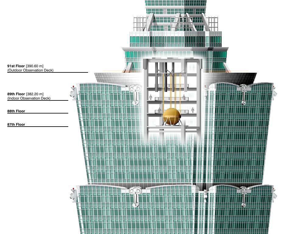
 MASSACHUSETTS INSTITUTE OF TECHNOLOGY Department of Mechanical Engineering.4 Dynamics and Control II Fall 7 Problem Set #9 Solution Posted: Sunday, Dec., 7. The.4 Tower system. The system parameters are
ẋ n = f n (x 1,...,x n,u 1,...,u m ) (5) y 1 = g 1 (x 1,...,x n,u 1,...,u m ) (6) y p = g p (x 1,...,x n,u 1,...,u m ) (7)
 (5) y 1 = g 1 (x 1,...,x n,u 1,...,u m ) (6) y p = g p (x 1,...,x n,u 1,...,u m ) (7)") EEE582 Topical Outline A.A. Rodriguez Fall 2007 GWC 352, 965-3712 The following represents a detailed topical outline of the course. It attempts to highlight most of the key concepts to be covered and
EEE582 Topical Outline A.A. Rodriguez Fall 2007 GWC 352, 965-3712 The following represents a detailed topical outline of the course. It attempts to highlight most of the key concepts to be covered and
APPPHYS 217 Tuesday 6 April 2010
 APPPHYS 7 Tuesday 6 April Stability and input-output performance: second-order systems Here we present a detailed example to draw connections between today s topics and our prior review of linear algebra
CDS 110: Lecture 2-2 Modeling Using Differential Equations
 CDS 110: Lecture 2-2 Modeling Using Differential Equations Richard M. Murray and Hideo Mabuchi 4 October 2006 Goals: Provide a more detailed description of the use of ODEs for modeling Provide examples
5HC99 Embedded Vision Control. Feedback Control Systems. dr. Dip Goswami Flux Department of Electrical Engineering
 5HC99 Embedded Vision Control Feedback Control Systems dr. Dip Goswami d.goswami@tue.nl Flux 04.135 Department of Electrical Engineering 1 Example Feedback control system: regulates the behavior of dynamical
Richiami di Controlli Automatici
 Richiami di Controlli Automatici Gianmaria De Tommasi 1 1 Università degli Studi di Napoli Federico II detommas@unina.it Ottobre 2012 Corsi AnsaldoBreda G. De Tommasi (UNINA) Richiami di Controlli Automatici
Problem Weight Score Total 100
 EE 350 EXAM IV 15 December 2010 Last Name (Print): First Name (Print): ID number (Last 4 digits): Section: DO NOT TURN THIS PAGE UNTIL YOU ARE TOLD TO DO SO Problem Weight Score 1 25 2 25 3 25 4 25 Total
D(s) G(s) A control system design definition
 G(s) A control system design definition") R E Compensation D(s) U Plant G(s) Y Figure 7. A control system design definition x x x 2 x 2 U 2 s s 7 2 Y Figure 7.2 A block diagram representing Eq. (7.) in control form z U 2 s z Y 4 z 2 s z 2 3 Figure
R E Compensation D(s) U Plant G(s) Y Figure 7. A control system design definition x x x 2 x 2 U 2 s s 7 2 Y Figure 7.2 A block diagram representing Eq. (7.) in control form z U 2 s z Y 4 z 2 s z 2 3 Figure
Dynamic Response. Assoc. Prof. Enver Tatlicioglu. Department of Electrical & Electronics Engineering Izmir Institute of Technology.
 Dynamic Response Assoc. Prof. Enver Tatlicioglu Department of Electrical & Electronics Engineering Izmir Institute of Technology Chapter 3 Assoc. Prof. Enver Tatlicioglu (EEE@IYTE) EE362 Feedback Control
Frequency methods for the analysis of feedback systems. Lecture 6. Loop analysis of feedback systems. Nyquist approach to study stability
 Lecture 6. Loop analysis of feedback systems 1. Motivation 2. Graphical representation of frequency response: Bode and Nyquist curves 3. Nyquist stability theorem 4. Stability margins Frequency methods
ECE317 : Feedback and Control
 ECE317 : Feedback and Control Lecture : Steady-state error Dr. Richard Tymerski Dept. of Electrical and Computer Engineering Portland State University 1 Course roadmap Modeling Analysis Design Laplace
Introduction to Feedback Control
 Introduction to Feedback Control Control System Design Why Control? Open-Loop vs Closed-Loop (Feedback) Why Use Feedback Control? Closed-Loop Control System Structure Elements of a Feedback Control System
State Regulator. Advanced Control. design of controllers using pole placement and LQ design rules
 Advanced Control State Regulator Scope design of controllers using pole placement and LQ design rules Keywords pole placement, optimal control, LQ regulator, weighting matrixes Prerequisites Contact state
EE C128 / ME C134 Fall 2014 HW 8 - Solutions. HW 8 - Solutions
 EE C28 / ME C34 Fall 24 HW 8 - Solutions HW 8 - Solutions. Transient Response Design via Gain Adjustment For a transfer function G(s) = in negative feedback, find the gain to yield a 5% s(s+2)(s+85) overshoot
Systems Analysis and Control
 Systems Analysis and Control Matthew M. Peet Arizona State University Lecture 8: Response Characteristics Overview In this Lecture, you will learn: Characteristics of the Response Stability Real Poles
Systems Analysis and Control
 Systems Analysis and Control Matthew M. Peet Illinois Institute of Technology Lecture 8: Response Characteristics Overview In this Lecture, you will learn: Characteristics of the Response Stability Real
Process Control & Instrumentation (CH 3040)
") First-order systems Process Control & Instrumentation (CH 3040) Arun K. Tangirala Department of Chemical Engineering, IIT Madras January - April 010 Lectures: Mon, Tue, Wed, Fri Extra class: Thu A first-order
First-order systems Process Control & Instrumentation (CH 3040) Arun K. Tangirala Department of Chemical Engineering, IIT Madras January - April 010 Lectures: Mon, Tue, Wed, Fri Extra class: Thu A first-order
Dynamics of structures
 Dynamics of structures 2.Vibrations: single degree of freedom system Arnaud Deraemaeker (aderaema@ulb.ac.be) 1 One degree of freedom systems in real life 2 1 Reduction of a system to a one dof system Example
Digital Control Systems
 Digital Control Systems Lecture Summary #4 This summary discussed some graphical methods their use to determine the stability the stability margins of closed loop systems. A. Nyquist criterion Nyquist
Automatic Control 2. Loop shaping. Prof. Alberto Bemporad. University of Trento. Academic year
 Automatic Control 2 Loop shaping Prof. Alberto Bemporad University of Trento Academic year 21-211 Prof. Alberto Bemporad (University of Trento) Automatic Control 2 Academic year 21-211 1 / 39 Feedback
Transfer function and linearization
 Transfer function and linearization Daniele Carnevale Dipartimento di Ing. Civile ed Ing. Informatica (DICII), University of Rome Tor Vergata Corso di Controlli Automatici, A.A. 24-25 Testo del corso:
STABILITY. Have looked at modeling dynamic systems using differential equations. and used the Laplace transform to help find step and impulse
 SIGNALS AND SYSTEMS: PAPER 3C1 HANDOUT 4. Dr David Corrigan 1. Electronic and Electrical Engineering Dept. corrigad@tcd.ie www.sigmedia.tv STABILITY Have looked at modeling dynamic systems using differential
Lecture 9 Time-domain properties of convolution systems
 EE 12 spring 21-22 Handout #18 Lecture 9 Time-domain properties of convolution systems impulse response step response fading memory DC gain peak gain stability 9 1 Impulse response if u = δ we have y(t)
Control Systems I. Lecture 5: Transfer Functions. Readings: Emilio Frazzoli. Institute for Dynamic Systems and Control D-MAVT ETH Zürich
 Control Systems I Lecture 5: Transfer Functions Readings: Emilio Frazzoli Institute for Dynamic Systems and Control D-MAVT ETH Zürich October 20, 2017 E. Frazzoli (ETH) Lecture 5: Control Systems I 20/10/2017
Problem Value
 GEORGIA INSTITUTE OF TECHNOLOGY SCHOOL of ELECTRICAL & COMPUTER ENGINEERING FINAL EXAM DATE: 30-Apr-04 COURSE: ECE-2025 NAME: GT #: LAST, FIRST Recitation Section: Circle the date & time when your Recitation
MAE 143B - Homework 7
 MAE 143B - Homework 7 6.7 Multiplying the first ODE by m u and subtracting the product of the second ODE with m s, we get m s m u (ẍ s ẍ i ) + m u b s (ẋ s ẋ u ) + m u k s (x s x u ) + m s b s (ẋ s ẋ u
APPLICATIONS FOR ROBOTICS
 Version: 1 CONTROL APPLICATIONS FOR ROBOTICS TEX d: Feb. 17, 214 PREVIEW We show that the transfer function and conditions of stability for linear systems can be studied using Laplace transforms. Table
Lecture 9. Welcome back! Coming week labs: Today: Lab 16 System Identification (2 sessions)
") 232 Welcome back! Coming week labs: Lecture 9 Lab 16 System Identification (2 sessions) Today: Review of Lab 15 System identification (ala ME4232) Time domain Frequency domain 1 Future Labs To develop
232 Welcome back! Coming week labs: Lecture 9 Lab 16 System Identification (2 sessions) Today: Review of Lab 15 System identification (ala ME4232) Time domain Frequency domain 1 Future Labs To develop
CHAPTER 7 : BODE PLOTS AND GAIN ADJUSTMENTS COMPENSATION
 CHAPTER 7 : BODE PLOTS AND GAIN ADJUSTMENTS COMPENSATION Objectives Students should be able to: Draw the bode plots for first order and second order system. Determine the stability through the bode plots.
Raktim Bhattacharya. . AERO 632: Design of Advance Flight Control System. Preliminaries
 . AERO 632: of Advance Flight Control System. Preliminaries Raktim Bhattacharya Laboratory For Uncertainty Quantification Aerospace Engineering, Texas A&M University. Preliminaries Signals & Systems Laplace
EECS C128/ ME C134 Final Wed. Dec. 15, am. Closed book. Two pages of formula sheets. No calculators.
 Name: SID: EECS C28/ ME C34 Final Wed. Dec. 5, 2 8- am Closed book. Two pages of formula sheets. No calculators. There are 8 problems worth points total. Problem Points Score 2 2 6 3 4 4 5 6 6 7 8 2 Total
L2 gains and system approximation quality 1
 Massachusetts Institute of Technology Department of Electrical Engineering and Computer Science 6.242, Fall 24: MODEL REDUCTION L2 gains and system approximation quality 1 This lecture discusses the utility
MASSACHUSETTS INSTITUTE OF TECHNOLOGY Department of Mechanical Engineering 2.04A Systems and Controls Spring 2013
 MASSACHUSETTS INSTITUTE OF TECHNOLOGY Department of Mechanical Engineering 2.04A Systems and Controls Spring 2013 Problem Set #4 Posted: Thursday, Mar. 7, 13 Due: Thursday, Mar. 14, 13 1. Sketch the Root
Discrete Systems. Step response and pole locations. Mark Cannon. Hilary Term Lecture
 Discrete Systems Mark Cannon Hilary Term 22 - Lecture 4 Step response and pole locations 4 - Review Definition of -transform: U() = Z{u k } = u k k k= Discrete transfer function: Y () U() = G() = Z{g k},
CDS 101/110: Lecture 10.3 Final Exam Review
 CDS 11/11: Lecture 1.3 Final Exam Review December 2, 216 Schedule: (1) Posted on the web Monday, Dec. 5 by noon. (2) Due Friday, Dec. 9, at 5: pm. (3) Determines 3% of your grade Instructions on Front
Differential Equations and Lumped Element Circuits
 Differential Equations and Lumped Element Circuits 8 Introduction Chapter 8 of the text discusses the numerical solution of ordinary differential equations. Differential equations and in particular linear
INTRODUCTION TO DIGITAL CONTROL
 ECE4540/5540: Digital Control Systems INTRODUCTION TO DIGITAL CONTROL.: Introduction In ECE450/ECE550 Feedback Control Systems, welearnedhow to make an analog controller D(s) to control a linear-time-invariant
Today (10/23/01) Today. Reading Assignment: 6.3. Gain/phase margin lead/lag compensator Ref. 6.4, 6.7, 6.10
 Today. Reading Assignment: 6.3. Gain/phase margin lead/lag compensator Ref. 6.4, 6.7, 6.10") Today Today (10/23/01) Gain/phase margin lead/lag compensator Ref. 6.4, 6.7, 6.10 Reading Assignment: 6.3 Last Time In the last lecture, we discussed control design through shaping of the loop gain GK:
Today Today (10/23/01) Gain/phase margin lead/lag compensator Ref. 6.4, 6.7, 6.10 Reading Assignment: 6.3 Last Time In the last lecture, we discussed control design through shaping of the loop gain GK:
6.1 Sketch the z-domain root locus and find the critical gain for the following systems K., the closed-loop characteristic equation is K + z 0.
 6. Sketch the z-domain root locus and find the critical gain for the following systems K (i) Gz () z 4. (ii) Gz K () ( z+ 9. )( z 9. ) (iii) Gz () Kz ( z. )( z ) (iv) Gz () Kz ( + 9. ) ( z. )( z 8. ) (i)
Review: transient and steady-state response; DC gain and the FVT Today s topic: system-modeling diagrams; prototype 2nd-order system
 Plan of the Lecture Review: transient and steady-state response; DC gain and the FVT Today s topic: system-modeling diagrams; prototype 2nd-order system Plan of the Lecture Review: transient and steady-state
AMME3500: System Dynamics & Control
 Stefan B. Williams May, 211 AMME35: System Dynamics & Control Assignment 4 Note: This assignment contributes 15% towards your final mark. This assignment is due at 4pm on Monday, May 3 th during Week 13
Homework 7 - Solutions
 Homework 7 - Solutions Note: This homework is worth a total of 48 points. 1. Compensators (9 points) For a unity feedback system given below, with G(s) = K s(s + 5)(s + 11) do the following: (c) Find the
ECE 3793 Matlab Project 3 Solution
 ECE 3793 Matlab Project 3 Solution Spring 27 Dr. Havlicek. (a) In text problem 9.22(d), we are given X(s) = s + 2 s 2 + 7s + 2 4 < Re {s} < 3. The following Matlab statements determine the partial fraction
Step Response for the Transfer Function of a Sensor
 Step Response f the Transfer Function of a Sens G(s)=Y(s)/X(s) of a sens with X(s) input and Y(s) output A) First Order Instruments a) First der transfer function G(s)=k/(1+Ts), k=gain, T = time constant
Prüfung Regelungstechnik I (Control Systems I) Übersetzungshilfe / Translation aid (English) To be returned at the end of the exam!
 Übersetzungshilfe / Translation aid (English) To be returned at the end of the exam!") Prüfung Regelungstechnik I (Control Systems I) Prof. Dr. Lino Guzzella 29. 8. 2 Übersetzungshilfe / Translation aid (English) To be returned at the end of the exam! Do not mark up this translation aid
Prüfung Regelungstechnik I (Control Systems I) Prof. Dr. Lino Guzzella 29. 8. 2 Übersetzungshilfe / Translation aid (English) To be returned at the end of the exam! Do not mark up this translation aid
Time Response of Systems
 Chapter 0 Time Response of Systems 0. Some Standard Time Responses Let us try to get some impulse time responses just by inspection: Poles F (s) f(t) s-plane Time response p =0 s p =0,p 2 =0 s 2 t p =
CDS 101/110a: Lecture 10-2 Control Systems Implementation
 CDS 101/110a: Lecture 10-2 Control Systems Implementation Richard M. Murray 5 December 2012 Goals Provide an overview of the key principles, concepts and tools from control theory - Classical control -
Topic # Feedback Control Systems
 Topic #19 16.31 Feedback Control Systems Stengel Chapter 6 Question: how well do the large gain and phase margins discussed for LQR map over to DOFB using LQR and LQE (called LQG)? Fall 2010 16.30/31 19
State Space Control D R. T A R E K A. T U T U N J I
 State Space Control D R. T A R E K A. T U T U N J I A D V A N C E D C O N T R O L S Y S T E M S M E C H A T R O N I C S E N G I N E E R I N G D E P A R T M E N T P H I L A D E L P H I A U N I V E R S I
EE 4343/ Control System Design Project LECTURE 10
 Copyright S. Ikenaga 998 All rights reserved EE 4343/5329 - Control System Design Project LECTURE EE 4343/5329 Homepage EE 4343/5329 Course Outline Design of Phase-lead and Phase-lag compensators using
Problem Value
 GEORGIA INSTITUTE OF TECHNOLOGY SCHOOL of ELECTRICAL & COMPUTER ENGINEERING FINAL EXAM DATE: 30-Apr-04 COURSE: ECE-2025 NAME: GT #: LAST, FIRST Recitation Section: Circle the date & time when your Recitation
CDS 101: Lecture 2.1 System Modeling
 CDS 101: Lecture 2.1 System Modeling Richard M. Murray 4 October 2004 Goals: Define what a model is and its use in answering questions about a system Introduce the concepts of state, dynamics, inputs and
Laboratory handout 5 Mode shapes and resonance
 laboratory handouts, me 34 82 Laboratory handout 5 Mode shapes and resonance In this handout, material and assignments marked as optional can be skipped when preparing for the lab, but may provide a useful
(a) Find the transfer function of the amplifier. Ans.: G(s) =
 Find the transfer function of the amplifier. Ans.: G(s) =") 126 INTRDUCTIN T CNTR ENGINEERING 10( s 1) (a) Find the transfer function of the amplifier. Ans.: (. 02s 1)(. 001s 1) (b) Find the expected percent overshoot for a step input for the closed-loop system
126 INTRDUCTIN T CNTR ENGINEERING 10( s 1) (a) Find the transfer function of the amplifier. Ans.: (. 02s 1)(. 001s 1) (b) Find the expected percent overshoot for a step input for the closed-loop system
(b) A unity feedback system is characterized by the transfer function. Design a suitable compensator to meet the following specifications:
 A unity feedback system is characterized by the transfer function. Design a suitable compensator to meet the following specifications:") 1. (a) The open loop transfer function of a unity feedback control system is given by G(S) = K/S(1+0.1S)(1+S) (i) Determine the value of K so that the resonance peak M r of the system is equal to 1.4.
1. (a) The open loop transfer function of a unity feedback control system is given by G(S) = K/S(1+0.1S)(1+S) (i) Determine the value of K so that the resonance peak M r of the system is equal to 1.4.
Laboratory handouts, ME 340
 Laboratory handouts, ME 340 This document contains summary theory, solved exercises, prelab assignments, lab instructions, and report assignments for Lab 4. 2014-2016 Harry Dankowicz, unless otherwise
MAE 143B - Homework 9
 MAE 143B - Homework 9 7.1 a) We have stable first-order poles at p 1 = 1 and p 2 = 1. For small values of ω, we recover the DC gain K = lim ω G(jω) = 1 1 = 2dB. Having this finite limit, our straight-line
Lab 3: Poles, Zeros, and Time/Frequency Domain Response
 ECEN 33 Linear Systems Spring 2 2-- P. Mathys Lab 3: Poles, Zeros, and Time/Frequency Domain Response of CT Systems Introduction Systems that are used for signal processing are very often characterized
School of Mechanical Engineering Purdue University. ME375 Dynamic Response - 1
 Dynamic Response of Linear Systems Linear System Response Superposition Principle Responses to Specific Inputs Dynamic Response of f1 1st to Order Systems Characteristic Equation - Free Response Stable
Dr Ian R. Manchester
 Week Content Notes 1 Introduction 2 Frequency Domain Modelling 3 Transient Performance and the s-plane 4 Block Diagrams 5 Feedback System Characteristics Assign 1 Due 6 Root Locus 7 Root Locus 2 Assign
Control Systems I. Lecture 4: Diagonalization, Modal Analysis, Intro to Feedback. Readings: Emilio Frazzoli
 Control Systems I Lecture 4: Diagonalization, Modal Analysis, Intro to Feedback Readings: Emilio Frazzoli Institute for Dynamic Systems and Control D-MAVT ETH Zürich October 13, 2017 E. Frazzoli (ETH)
Core Concepts Review. Orthogonality of Complex Sinusoids Consider two (possibly non-harmonic) complex sinusoids
 complex sinusoids") Overview of Continuous-Time Fourier Transform Topics Definition Compare & contrast with Laplace transform Conditions for existence Relationship to LTI systems Examples Ideal lowpass filters Relationship
Overview of Continuous-Time Fourier Transform Topics Definition Compare & contrast with Laplace transform Conditions for existence Relationship to LTI systems Examples Ideal lowpass filters Relationship
Course roadmap. Step response for 2nd-order system. Step response for 2nd-order system
 ME45: Control Systems Lecture Time response of nd-order systems Prof. Clar Radcliffe and Prof. Jongeun Choi Department of Mechanical Engineering Michigan State University Modeling Laplace transform Transfer
Chapter 3. State Feedback - Pole Placement. Motivation
 Chapter 3 State Feedback - Pole Placement Motivation Whereas classical control theory is based on output feedback, this course mainly deals with control system design by state feedback. This model-based
ECE-320: Linear Control Systems Homework 8. 1) For one of the rectilinear systems in lab, I found the following state variable representations:
 For one of the rectilinear systems in lab, I found the following state variable representations:") ECE-30: Linear Control Systems Homework 8 Due: Thursday May 6, 00 at the beginning of class ) For one of the rectilinear systems in lab, I found the following state variable representations: 0 0 q q+ 74.805.6469
ECE-30: Linear Control Systems Homework 8 Due: Thursday May 6, 00 at the beginning of class ) For one of the rectilinear systems in lab, I found the following state variable representations: 0 0 q q+ 74.805.6469
FREQUENCY-RESPONSE DESIGN
 ECE45/55: Feedback Control Systems. 9 FREQUENCY-RESPONSE DESIGN 9.: PD and lead compensation networks The frequency-response methods we have seen so far largely tell us about stability and stability margins
Lecture 5: Frequency domain analysis: Nyquist, Bode Diagrams, second order systems, system types
 Lecture 5: Frequency domain analysis: Nyquist, Bode Diagrams, second order systems, system types Venkata Sonti Department of Mechanical Engineering Indian Institute of Science Bangalore, India, 562 This
Classify a transfer function to see which order or ramp it can follow and with which expected error.
 Dr. J. Tani, Prof. Dr. E. Frazzoli 5-059-00 Control Systems I (Autumn 208) Exercise Set 0 Topic: Specifications for Feedback Systems Discussion: 30.. 208 Learning objectives: The student can grizzi@ethz.ch,
Introduction. Performance and Robustness (Chapter 1) Advanced Control Systems Spring / 31
 Advanced Control Systems Spring / 31") Introduction Classical Control Robust Control u(t) y(t) G u(t) G + y(t) G : nominal model G = G + : plant uncertainty Uncertainty sources : Structured : parametric uncertainty, multimodel uncertainty Unstructured
Introduction Classical Control Robust Control u(t) y(t) G u(t) G + y(t) G : nominal model G = G + : plant uncertainty Uncertainty sources : Structured : parametric uncertainty, multimodel uncertainty Unstructured
Introduction ODEs and Linear Systems
 BENG 221 Mathematical Methods in Bioengineering ODEs and Linear Systems Gert Cauwenberghs Department of Bioengineering UC San Diego 1.1 Course Objectives 1. Acquire methods for quantitative analysis and
VALLIAMMAI ENGINEERING COLLEGE SRM Nagar, Kattankulathur
 VALLIAMMAI ENGINEERING COLLEGE SRM Nagar, Kattankulathur 603 203. DEPARTMENT OF ELECTRONICS & COMMUNICATION ENGINEERING SUBJECT QUESTION BANK : EC6405 CONTROL SYSTEM ENGINEERING SEM / YEAR: IV / II year
Control of Mobile Robots
 Control of Mobile Robots Regulation and trajectory tracking Prof. Luca Bascetta (luca.bascetta@polimi.it) Politecnico di Milano Dipartimento di Elettronica, Informazione e Bioingegneria Organization and
Control Systems Design
 ELEC4410 Control Systems Design Lecture 18: State Feedback Tracking and State Estimation Julio H. Braslavsky julio@ee.newcastle.edu.au School of Electrical Engineering and Computer Science Lecture 18:
Massachusetts Institute of Technology
 Massachusetts Institute of Technology Department of Electrical Engineering and Computer Science 6.11: Introduction to Communication, Control and Signal Processing QUIZ 1, March 16, 21 QUESTION BOOKLET
Control Systems Design
 ELEC4410 Control Systems Design Lecture 13: Stability Julio H. Braslavsky julio@ee.newcastle.edu.au School of Electrical Engineering and Computer Science Lecture 13: Stability p.1/20 Outline Input-Output
Intro to Frequency Domain Design
 Intro to Frequency Domain Design MEM 355 Performance Enhancement of Dynamical Systems Harry G. Kwatny Department of Mechanical Engineering & Mechanics Drexel University Outline Closed Loop Transfer Functions
MEM 355 Performance Enhancement of Dynamical Systems
 MEM 355 Performance Enhancement of Dynamical Systems Frequency Domain Design Harry G. Kwatny Department of Mechanical Engineering & Mechanics Drexel University 5/8/25 Outline Closed Loop Transfer Functions
9. Two-Degrees-of-Freedom Design
 9. Two-Degrees-of-Freedom Design In some feedback schemes we have additional degrees-offreedom outside the feedback path. For example, feed forwarding known disturbance signals or reference signals. In
] [ 200. ] 3 [ 10 4 s. [ ] s + 10 [ P = s [ 10 8 ] 3. s s (s 1)(s 2) series compensator ] 2. s command pre-filter [ 0.
![] [ 200. ] 3 [ 10 4 s. [ ] s + 10 [ P = s [ 10 8 ] 3. s s (s 1)(s 2) series compensator ] 2. s command pre-filter [ 0.](/thumbs/92/110643216.jpg "] [ 200. ] 3 [ 10 4 s. [ ] s + 10 [ P = s [ 10 8 ] 3. s s (s 1)(s 2) series compensator ] 2. s command pre-filter [ 0.") EEE480 Exam 2, Spring 204 A.A. Rodriguez Rules: Calculators permitted, One 8.5 sheet, closed notes/books, open minds GWC 352, 965-372 Problem (Analysis of a Feedback System) Consider the feedback system
EEE480 Exam 2, Spring 204 A.A. Rodriguez Rules: Calculators permitted, One 8.5 sheet, closed notes/books, open minds GWC 352, 965-372 Problem (Analysis of a Feedback System) Consider the feedback system
CYBER EXPLORATION LABORATORY EXPERIMENTS
 CYBER EXPLORATION LABORATORY EXPERIMENTS 1 2 Cyber Exploration oratory Experiments Chapter 2 Experiment 1 Objectives To learn to use MATLAB to: (1) generate polynomial, (2) manipulate polynomials, (3)
Active Control? Contact : Website : Teaching
 Active Control? Contact : bmokrani@ulb.ac.be Website : http://scmero.ulb.ac.be Teaching Active Control? Disturbances System Measurement Control Controler. Regulator.,,, Aims of an Active Control Disturbances