1 Introduction to shells
|
|
|
- Spencer McKenzie
- 5 years ago
- Views:
Transcription


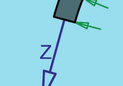

1 1 Introduction to shells Transparent Shells. Form, Topology, Structure. 1. Edition. Hans Schober Ernst & Sohn GmbH & Co. KG. Published 2015 by Ernst & Sohn GmbH & Co. KG Z = p R
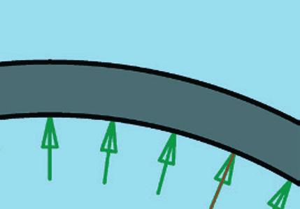
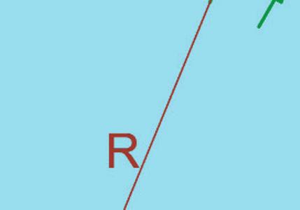
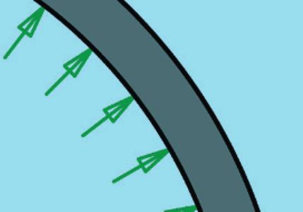
2 1 Introduction to shells 1.1 Designing shells Shells are naturally beautiful and efficient structures. The reason for this is that their flowing double-curved form is able to transfer loads without bending, by transmitting tension and compression forces solely within the surface. They therefore require significantly less material than flat structures under bending stress, as for instance beam or slab structures. There is however a discrepancy between favourable load-bearing behaviour and difficult double-curved construction. Solving this discrepancy is an important step towards successful shell design. To design a transparent or glazed shell, it is necessary to fragment it into bars, thus creating a structure that offers maximum transparency. Double-curved surface structures with a triangular mesh net provide a favourable basis for optimal transparency. An essential condition for single-layer membrane shells is to transfer forces solely within the surface, and to do so without a substantial bar deflection. It is the triangular grid alone that is fit for this purpose. The economic efficiency of transparent shells depends largely on the way the grid members are joined in the nodes, and on the shape of the cladding. Today, high performance software facilitates the calculation of shells. These programmes offer easy to use geometry and load input functions, as well as a clear visualisation of results. Nonetheless, a structural engineer needs sound theoretical knowledge of the load bearing behaviour of shells to make sure that the right decisions towards an aesthetic and efficient structure are made right from the early design stage. Although an incorrect structural concept can be made feasible by means of computing and determining the corresponding dimensions of load-bearing members, the result will be neither effective, nor innovative. It is therefore vital to be in possession of adequate knowledge about the load bearing behaviour of shell structures. The design should always strive towards a membrane; which is to say, a moment-free state. The basis is therefore a continuous double-curved shape. Contrary to an arch, where a moment-free load transfer is only possible, if the geometrical form matches the type of load (thrust line, Fig. 1.1), a single shell form is able to transfer diverse loads moment-free. The support of the shells should be in accordance with the membrane theory. This means the thrust line is tangent to the shell surface and point loads on the shell surface must either be avoided or applied as a distributed load. The bending stresses arising from the compatibility conditions within the shell can be reliably determined by computer. In a membrane state the shell forces can easily be estimated. These simple estimation methods are of great importance for the design process, and to doublecheck computer results. The membrane forces can easily be estimated for various rotation-symmetrically stressed shells, once the resultant load P 1 above the horizontal cut is known (Fig. 1.2). 14
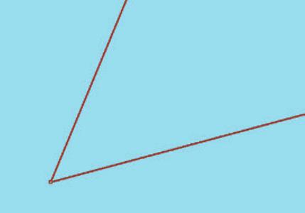
3 Thrust line for arches under dead load (catenary) Thrust line for arches under uniformly distributed load x 2 = 2p y (parabola) support forces: (1) Fig. 1.1 The thrust line of an arch depends on the load (see section 4.2 for the estimation of normal forces and bending moments in arch structures, or barrel vaults) Meridian force (2) The ring force n can easily be determined by double application of the ring formula Z = p R. n produces a deviation force u in outward direction of and the ring formula Z = p R produces a ring force The external load p induces a radial load component p r. The ring formula Z = p R gives us the ring force n = p r R and therefore ring force Fig. 1.2 Estimation of membrane forces n, n of a rotational shell, R is the radius of curvature in the meridional line of pressure, R in the direction of the hoop. (3) 15 1 Introduction to shells
4 In the special case of a spherical shell under uniformly distributed load the radial load component is p r = p cos 2 and the resultant load is P 1 = p R R sin 2. Under dead load g the radial load component is p r = g cos and the resultant load is P 1 = 2 g R 2 (1 - cos ). To obtain the membrane forces of the spherical shell p r and P 1 are to be substituted in the equation above. These are compiled in Fig Regarding other cases, we refer to the corresponding literature. Spherical shell under uniformly distributed load p Components of meridian force n : Horizontal component n h cos (4) Vertical component n v sin Meridian force n from uniformly distributed load p Hoop force n from uniformly distributed load p Spherical shell under dead load g Components of meridian force n : Horizontal component n h cos (5) Vertical component n v sin Meridian force n from dead load g Hoop force n from dead load g Fig. 1.3 Membrane forces of a spherical shell If the support of a shell does not comprise optimum membrane supports, if only vertical support forces can be absorbed for example; a stiff edge beam can create a membrane-like state that permits much lower bending moments within the shell that diminish quickly. Hoop forces can easily be determined in manual calculations, as long as the edge beam is formed as a ring (Fig. 1.4). 16
 (tension at the top, compression at the bottom) Torsional moment = 0 Fig. 1.")

![bending moment M, which is distributed into tensile and compressive hoop forces [13].](/docs-images/86/94555612/images/5-3.jpg "This characteristic has been implemented several times in curved footbridges [14].")
5 Ring beam under radial load p (rotation-symmetric) Tensile hoop force Z = p R (6) Ring beam under carding moment m = q e (rotation-symmetric) Bending moment M = m R (7) (tension at the top, compression at the bottom) Torsional moment = 0 Fig. 1.4 Sectional forces in the ring beam induced by radial load and carding moment. A distinctive characteristic of a ring beam under carding moment m = q e is that the stress resultant mobilised within the ring is not a torsion, but a bending moment M, which is distributed into tensile and compressive hoop forces [13]. This characteristic has been implemented several times in curved footbridges [14]. Due to the equilibrium of forces, a resulting transverse force Q applied to the ring beam via radial forces induces the shear forces (Fig. 1.5). Q = 0 results in: maximum shear force from Q. (8) Fig. 1.5 Shear forces t at the ring beam 17 1 Introduction to shells
6
The Islamic University of Gaza Department of Civil Engineering ENGC Design of Spherical Shells (Domes)
") The Islamic University of Gaza Department of Civil Engineering ENGC 6353 Design of Spherical Shells (Domes) Shell Structure A thin shell is defined as a shell with a relatively small thickness, compared
The Islamic University of Gaza Department of Civil Engineering ENGC 6353 Design of Spherical Shells (Domes) Shell Structure A thin shell is defined as a shell with a relatively small thickness, compared
PLATE GIRDERS II. Load. Web plate Welds A Longitudinal elevation. Fig. 1 A typical Plate Girder
 16 PLATE GIRDERS II 1.0 INTRODUCTION This chapter describes the current practice for the design of plate girders adopting meaningful simplifications of the equations derived in the chapter on Plate Girders
Lecture 15 Strain and stress in beams
 Spring, 2019 ME 323 Mechanics of Materials Lecture 15 Strain and stress in beams Reading assignment: 6.1 6.2 News: Instructor: Prof. Marcial Gonzalez Last modified: 1/6/19 9:42:38 PM Beam theory (@ ME
If the number of unknown reaction components are equal to the number of equations, the structure is known as statically determinate.
 1 of 6 EQUILIBRIUM OF A RIGID BODY AND ANALYSIS OF ETRUCTURAS II 9.1 reactions in supports and joints of a two-dimensional structure and statically indeterminate reactions: Statically indeterminate structures
Theory of structure I 2006/2013. Chapter one DETERMINACY & INDETERMINACY OF STRUCTURES
 Chapter one DETERMINACY & INDETERMINACY OF STRUCTURES Introduction A structure refers to a system of connected parts used to support a load. Important examples related to civil engineering include buildings,
Basis of Structural Design
 Basis of Structural Design Course 2 Structural action: cables and arches Course notes are available for download at http://www.ct.upt.ro/users/aurelstratan/ Structural action Structural action: the way
Chapter 3. Load and Stress Analysis
 Chapter 3 Load and Stress Analysis 2 Shear Force and Bending Moments in Beams Internal shear force V & bending moment M must ensure equilibrium Fig. 3 2 Sign Conventions for Bending and Shear Fig. 3 3
T4/1 Analysis of a barrel vault simplified calculation
 T4. MASONRY STRUCTURES 1/4 T4/1 Analysis of a barrel vault simplified calculation Exercise: Check the given masonry vault for symmetrical loading! ata: q k = 4 kn/m (live load) ρ masonry = 17 kn/m 3 (specific
STRESS STRAIN AND DEFORMATION OF SOLIDS, STATES OF STRESS
 1 UNIT I STRESS STRAIN AND DEFORMATION OF SOLIDS, STATES OF STRESS 1. Define: Stress When an external force acts on a body, it undergoes deformation. At the same time the body resists deformation. The
ANALYSIS RADIAL FOLDED PLATE
 ANALYSIS RADIAL FOLDED PLATE Ms.Pranoti Satish Bhamare 1, Prajakta S. Bramhankar 2, Pooja G. Baviskar 3 1,2,3 Assistant Professor, Department of Civil Engineering, Guru Gobind Singh College of Engineering
If you take CT5143 instead of CT4143 then write this at the first of your answer sheets and skip problem 4 and 6.
 Delft University of Technology Faculty of Civil Engineering and Geosciences Structural Mechanics Section Write your name and study number at the top right-hand of your work. Exam CT4143 Shell Analysis
Analysis of Composite Pressure Vessels
 Analysis of Composite Pressure Vessels Reza Mohammadzadeh Gheshlaghi 1 Mohammad Hassan Hojjati Hamid Reza Mohammadi Daniali 3 1 Engineering Research Centre, Tabriz, Iran,3 Department of Mechanical Engineering,
Beams are bars of material that support. Beams are common structural members. Beams can support both concentrated and distributed loads
 Outline: Review External Effects on Beams Beams Internal Effects Sign Convention Shear Force and Bending Moment Diagrams (text method) Relationships between Loading, Shear Force and Bending Moments (faster
COURSE TITLE : APPLIED MECHANICS & STRENGTH OF MATERIALS COURSE CODE : 4017 COURSE CATEGORY : A PERIODS/WEEK : 6 PERIODS/ SEMESTER : 108 CREDITS : 5
 COURSE TITLE : APPLIED MECHANICS & STRENGTH OF MATERIALS COURSE CODE : 4017 COURSE CATEGORY : A PERIODS/WEEK : 6 PERIODS/ SEMESTER : 108 CREDITS : 5 TIME SCHEDULE MODULE TOPICS PERIODS 1 Simple stresses
1. The general principles of the stability of masonry
 On lines of thrust and stability of masonry arches V. Quintas D^arfamafzfo ok EsYrwcfwra? ^ ^z/?c6zczo^, E. 71&AM Universidad Politecnica de Madrid, Avda. Juan de Herrera, 4; Abstract The use of lines
FLEXIBILITY METHOD FOR INDETERMINATE FRAMES
 UNIT - I FLEXIBILITY METHOD FOR INDETERMINATE FRAMES 1. What is meant by indeterminate structures? Structures that do not satisfy the conditions of equilibrium are called indeterminate structure. These
Mechanical Principles
 Unit 4: Mechanical Principles Unit code: F/601/1450 QCF level: 5 Credit value: 15 Aim This unit aims to develop learners understanding of an extended range of mechanical principles that underpin the design
2012 MECHANICS OF SOLIDS
 R10 SET - 1 II B.Tech II Semester, Regular Examinations, April 2012 MECHANICS OF SOLIDS (Com. to ME, AME, MM) Time: 3 hours Max. Marks: 75 Answer any FIVE Questions All Questions carry Equal Marks ~~~~~~~~~~~~~~~~~~~~~~
(Refer Slide Time: 2:43-03:02)
") Strength of Materials Prof. S. K. Bhattacharyya Department of Civil Engineering Indian Institute of Technology, Kharagpur Lecture - 34 Combined Stresses I Welcome to the first lesson of the eighth module
Strength of Materials Prof. S. K. Bhattacharyya Department of Civil Engineering Indian Institute of Technology, Kharagpur Lecture - 34 Combined Stresses I Welcome to the first lesson of the eighth module
Study of the transitional shift between plates and shallow shells
 Study of the transitional shift between plates and shallow shells Mohamad Daoud 1, Moayyad Al-Nasra 2 1 Civil engineering Department, Zarqa University 2 Civil and Infrastructure Engineering Department,
Sabah Shawkat Cabinet of Structural Engineering Walls carrying vertical loads should be designed as columns. Basically walls are designed in
 Sabah Shawkat Cabinet of Structural Engineering 17 3.6 Shear walls Walls carrying vertical loads should be designed as columns. Basically walls are designed in the same manner as columns, but there are
What is a shell structure and how do they work?
 1 What is a shell structure and how do they work? Classification of structural shapes Structures can be classified in many ways according to their shape, their function and the materials from which they
Module 6. Approximate Methods for Indeterminate Structural Analysis. Version 2 CE IIT, Kharagpur
 Module 6 Approximate Methods for Indeterminate Structural Analysis Lesson 35 Indeterminate Trusses and Industrial rames Instructional Objectives: After reading this chapter the student will be able to
CHAPTER 5 PROPOSED WARPING CONSTANT
 122 CHAPTER 5 PROPOSED WARPING CONSTANT 5.1 INTRODUCTION Generally, lateral torsional buckling is a major design aspect of flexure members composed of thin-walled sections. When a thin walled section is
UNIT- I Thin plate theory, Structural Instability:
 UNIT- I Thin plate theory, Structural Instability: Analysis of thin rectangular plates subject to bending, twisting, distributed transverse load, combined bending and in-plane loading Thin plates having
ε t increases from the compressioncontrolled Figure 9.15: Adjusted interaction diagram
 CHAPTER NINE COLUMNS 4 b. The modified axial strength in compression is reduced to account for accidental eccentricity. The magnitude of axial force evaluated in step (a) is multiplied by 0.80 in case
OUTCOME 1 - TUTORIAL 3 BENDING MOMENTS. You should judge your progress by completing the self assessment exercises. CONTENTS
 Unit 2: Unit code: QCF Level: 4 Credit value: 15 Engineering Science L/601/1404 OUTCOME 1 - TUTORIAL 3 BENDING MOMENTS 1. Be able to determine the behavioural characteristics of elements of static engineering
FINITE ELEMENT ANALYSIS OF TAPERED COMPOSITE PLATE GIRDER WITH A NON-LINEAR VARYING WEB DEPTH
 Journal of Engineering Science and Technology Vol. 12, No. 11 (2017) 2839-2854 School of Engineering, Taylor s University FINITE ELEMENT ANALYSIS OF TAPERED COMPOSITE PLATE GIRDER WITH A NON-LINEAR VARYING
Members Subjected to Torsional Loads
 Members Subjected to Torsional Loads Torsion of circular shafts Definition of Torsion: Consider a shaft rigidly clamped at one end and twisted at the other end by a torque T = F.d applied in a plane perpendicular
Longitudinal buckling of slender pressurised tubes
 Fluid Structure Interaction VII 133 Longitudinal buckling of slender pressurised tubes S. Syngellakis Wesse Institute of Technology, UK Abstract This paper is concerned with Euler buckling of long slender
: APPLIED MECHANICS & STRENGTH OF MATERIALS COURSE CODE : 4021 COURSE CATEGORY : A PERIODS/ WEEK : 5 PERIODS/ SEMESTER : 75 CREDIT : 5 TIME SCHEDULE
 COURSE TITLE : APPLIED MECHANICS & STRENGTH OF MATERIALS COURSE CODE : 4021 COURSE CATEGORY : A PERIODS/ WEEK : 5 PERIODS/ SEMESTER : 75 CREDIT : 5 TIME SCHEDULE MODULE TOPIC PERIODS 1 Simple stresses
202 Index. failure, 26 field equation, 122 force, 1
 Index acceleration, 12, 161 admissible function, 155 admissible stress, 32 Airy's stress function, 122, 124 d'alembert's principle, 165, 167, 177 amplitude, 171 analogy, 76 anisotropic material, 20 aperiodic
SOLUTION (17.3) Known: A simply supported steel shaft is connected to an electric motor with a flexible coupling.
 Known: A simply supported steel shaft is connected to an electric motor with a flexible coupling.") SOLUTION (17.3) Known: A simply supported steel shaft is connected to an electric motor with a flexible coupling. Find: Determine the value of the critical speed of rotation for the shaft. Schematic and
SOLUTION (17.3) Known: A simply supported steel shaft is connected to an electric motor with a flexible coupling. Find: Determine the value of the critical speed of rotation for the shaft. Schematic and
CE6306 STRENGTH OF MATERIALS TWO MARK QUESTIONS WITH ANSWERS ACADEMIC YEAR
 CE6306 STRENGTH OF MATERIALS TWO MARK QUESTIONS WITH ANSWERS ACADEMIC YEAR 2014-2015 UNIT - 1 STRESS, STRAIN AND DEFORMATION OF SOLIDS PART- A 1. Define tensile stress and tensile strain. The stress induced
Stress Analysis of Radial and Non- Radial Nozzle Connections in Ellipsoidal Head Pressure Vessel
 Journal of Mechanical Engineering Vol. 10, No. 1, 67-83, 2013 Stress Analysis of Radial and Non- Radial Nozzle Connections in Ellipsoidal Head Pressure Vessel Haszeme Abu Kasim 1, a Professor Dr. Ir. Wahyu
END-LOADED SHALLOW CURVED BEAMS
 Last edited by CLD on 2/20/11. ENDLOADED SHALLOW CURVED BEAMS Clive L. Dym, F. ASCE Fletcher Jones Professor of Engineering Design Department of Engineering Harvey Mudd College Claremont, CA 91711 ABSTRACT
THEORY OF PLATES AND SHELLS
 THEORY OF PLATES AND SHELLS S. TIMOSHENKO Professor Emeritus of Engineering Mechanics Stanford University S. WOINOWSKY-KRIEGER Professor of Engineering Mechanics Laval University SECOND EDITION MCGRAW-HILL
ME Final Exam. PROBLEM NO. 4 Part A (2 points max.) M (x) y. z (neutral axis) beam cross-sec+on. 20 kip ft. 0.2 ft. 10 ft. 0.1 ft.
 M (x) y. z (neutral axis) beam cross-sec+on. 20 kip ft. 0.2 ft. 10 ft. 0.1 ft.") ME 323 - Final Exam Name December 15, 2015 Instructor (circle) PROEM NO. 4 Part A (2 points max.) Krousgrill 11:30AM-12:20PM Ghosh 2:30-3:20PM Gonzalez 12:30-1:20PM Zhao 4:30-5:20PM M (x) y 20 kip ft 0.2
ME 323 - Final Exam Name December 15, 2015 Instructor (circle) PROEM NO. 4 Part A (2 points max.) Krousgrill 11:30AM-12:20PM Ghosh 2:30-3:20PM Gonzalez 12:30-1:20PM Zhao 4:30-5:20PM M (x) y 20 kip ft 0.2
CHAPTER 4: BENDING OF BEAMS
 (74) CHAPTER 4: BENDING OF BEAMS This chapter will be devoted to the analysis of prismatic members subjected to equal and opposite couples M and M' acting in the same longitudinal plane. Such members are
Chapter 3. Load and Stress Analysis. Lecture Slides
 Lecture Slides Chapter 3 Load and Stress Analysis 2015 by McGraw Hill Education. This is proprietary material solely for authorized instructor use. Not authorized for sale or distribution in any manner.
Theory of Structures
 SAMPLE STUDY MATERIAL Postal Correspondence Course GATE, IES & PSUs Civil Engineering Theory of Structures C O N T E N T 1. ARCES... 3-14. ROLLING LOADS AND INFLUENCE LINES. 15-9 3. DETERMINACY AND INDETERMINACY..
Stress Transformation Equations: u = +135 (Fig. a) s x = 80 MPa s y = 0 t xy = 45 MPa. we obtain, cos u + t xy sin 2u. s x = s x + s y.
 s x = 80 MPa s y = 0 t xy = 45 MPa. we obtain, cos u + t xy sin 2u. s x = s x + s y.") 014 Pearson Education, Inc., Upper Saddle River, NJ. All rights reserved. This material is protected under all copyright laws as they currently 9 7. Determine the normal stress and shear stress acting
014 Pearson Education, Inc., Upper Saddle River, NJ. All rights reserved. This material is protected under all copyright laws as they currently 9 7. Determine the normal stress and shear stress acting
PRACTICE 2 PROYECTO Y CONSTRUCCIÓN DE PUENTES. 1º Máster Ingeniería de Caminos. E.T.S.I. Caminos, canales y puertos (Ciudad Real) 01/06/2016
 01/06/2016") PRACTICE 2 PROYECTO Y CONSTRUCCIÓN DE PUENTES 1º Máster Ingeniería de Caminos E.T.S.I. Caminos, canales y puertos (Ciudad Real) 01/06/2016 AUTHOR: CONTENT 1. INTRODUCTION... 3 2. BRIDGE GEOMETRY AND MATERIAL...
PRACTICE 2 PROYECTO Y CONSTRUCCIÓN DE PUENTES 1º Máster Ingeniería de Caminos E.T.S.I. Caminos, canales y puertos (Ciudad Real) 01/06/2016 AUTHOR: CONTENT 1. INTRODUCTION... 3 2. BRIDGE GEOMETRY AND MATERIAL...
Lecture Slides. Chapter 4. Deflection and Stiffness. The McGraw-Hill Companies 2012
 Lecture Slides Chapter 4 Deflection and Stiffness The McGraw-Hill Companies 2012 Chapter Outline Force vs Deflection Elasticity property of a material that enables it to regain its original configuration
Module 2 Stresses in machine elements. Version 2 ME, IIT Kharagpur
 Module Stresses in machine elements Lesson Compound stresses in machine parts Instructional Objectives t the end of this lesson, the student should be able to understand Elements of force system at a beam
Analysis of Catalyst Support Ring in a pressure vessel based on ASME Section VIII Division 2 using ANSYS software
 IJSRD - International Journal for Scientific Research & Development Vol. 1, Issue 3, 2013 ISSN (online): 2321-0613 Analysis of Catalyst Support Ring in a pressure vessel based on ASME Section VIII Division
Improving fire resistance of existing concrete slabs by concrete topping
 Improving fire resistance of existing concrete slabs by concrete topping Is EN 1992-1-2 annex E telling the truth, and can it be used? Tom Molkens StuBeCo bvba, Overpelt - Belgium Structures in Fire Forum
Flexure: Behavior and Nominal Strength of Beam Sections
 4 5000 4000 (increased d ) (increased f (increased A s or f y ) c or b) Flexure: Behavior and Nominal Strength of Beam Sections Moment (kip-in.) 3000 2000 1000 0 0 (basic) (A s 0.5A s ) 0.0005 0.001 0.0015
L13 Structural Engineering Laboratory
 LABORATORY PLANNING GUIDE L13 Structural Engineering Laboratory Content Covered subjects according to the curriculum of Structural Engineering... 2 Main concept... 4 Initial training provided for laboratory
PRESSURE VESSELS & PRESSURE CABINS FOR BLENDED WING BODIES
 PRESSURE VESSELS & PRESSURE CABINS FOR BLENDED WING BODIES F.J.J.M.M. Geuskens, O.K. Bergsma 2, S. Koussios 2 & A. Beukers 3 PhD Researcher, 2 Associate professor, 3 Professor / DPCS, TU Delft Kluyverweg,
Due Tuesday, September 21 st, 12:00 midnight
 Due Tuesday, September 21 st, 12:00 midnight The first problem discusses a plane truss with inclined supports. You will need to modify the MatLab software from homework 1. The next 4 problems consider
D : SOLID MECHANICS. Q. 1 Q. 9 carry one mark each.
 GTE 2016 Q. 1 Q. 9 carry one mark each. D : SOLID MECHNICS Q.1 single degree of freedom vibrating system has mass of 5 kg, stiffness of 500 N/m and damping coefficient of 100 N-s/m. To make the system
R13. II B. Tech I Semester Regular Examinations, Jan MECHANICS OF SOLIDS (Com. to ME, AME, AE, MTE) PART-A
 PART-A") SET - 1 II B. Tech I Semester Regular Examinations, Jan - 2015 MECHANICS OF SOLIDS (Com. to ME, AME, AE, MTE) Time: 3 hours Max. Marks: 70 Note: 1. Question Paper consists of two parts (Part-A and Part-B)
SET - 1 II B. Tech I Semester Regular Examinations, Jan - 2015 MECHANICS OF SOLIDS (Com. to ME, AME, AE, MTE) Time: 3 hours Max. Marks: 70 Note: 1. Question Paper consists of two parts (Part-A and Part-B)
KINGS COLLEGE OF ENGINEERING DEPARTMENT OF MECHANICAL ENGINEERING QUESTION BANK. Subject code/name: ME2254/STRENGTH OF MATERIALS Year/Sem:II / IV
 KINGS COLLEGE OF ENGINEERING DEPARTMENT OF MECHANICAL ENGINEERING QUESTION BANK Subject code/name: ME2254/STRENGTH OF MATERIALS Year/Sem:II / IV UNIT I STRESS, STRAIN DEFORMATION OF SOLIDS PART A (2 MARKS)
Members Subjected to Combined Loads
 Members Subjected to Combined Loads Combined Bending & Twisting : In some applications the shaft are simultaneously subjected to bending moment M and Torque T.The Bending moment comes on the shaft due
Materials: engineering, science, processing and design, 2nd edition Copyright (c)2010 Michael Ashby, Hugh Shercliff, David Cebon.
2010 Michael Ashby, Hugh Shercliff, David Cebon.") Modes of Loading (1) tension (a) (2) compression (b) (3) bending (c) (4) torsion (d) and combinations of them (e) Figure 4.2 1 Standard Solution to Elastic Problems Three common modes of loading: (a) tie
Modes of Loading (1) tension (a) (2) compression (b) (3) bending (c) (4) torsion (d) and combinations of them (e) Figure 4.2 1 Standard Solution to Elastic Problems Three common modes of loading: (a) tie
A CONNECTION ELEMENT FOR MODELLING END-PLATE CONNECTIONS IN FIRE
 A CONNECTION ELEMENT OR MODELLING END-PLATE CONNECTIONS IN IRE Dr Zhaohui Huang Department of Civil & Structural Engineering, University of Sheffield 22 September 29 1. INTRODUCTION Three approaches for
Influence of residual stresses in the structural behavior of. tubular columns and arches. Nuno Rocha Cima Gomes
 October 2014 Influence of residual stresses in the structural behavior of Abstract tubular columns and arches Nuno Rocha Cima Gomes Instituto Superior Técnico, Universidade de Lisboa, Portugal Contact:
Simulation of Geometrical Cross-Section for Practical Purposes
 Simulation of Geometrical Cross-Section for Practical Purposes Bhasker R.S. 1, Prasad R. K. 2, Kumar V. 3, Prasad P. 4 123 Department of Mechanical Engineering, R.D. Engineering College, Ghaziabad, UP,
Available online at ScienceDirect. Procedia Engineering 84 (2014 )
") Available online at www.sciencedirect.com ScienceDirect Procedia Engineering 84 (2014 ) 898 905 2014ISSST, 2014 International Symposium on Safety Science and Technology Study on dynamic numerical simulation
Available online at www.sciencedirect.com ScienceDirect Procedia Engineering 84 (2014 ) 898 905 2014ISSST, 2014 International Symposium on Safety Science and Technology Study on dynamic numerical simulation
[8] Bending and Shear Loading of Beams
![[8] Bending and Shear Loading of Beams](/thumbs/92/110949676.jpg "[8] Bending and Shear Loading of Beams") [8] Bending and Shear Loading of Beams Page 1 of 28 [8] Bending and Shear Loading of Beams [8.1] Bending of Beams (will not be covered in class) [8.2] Bending Strain and Stress [8.3] Shear in Straight
[8] Bending and Shear Loading of Beams Page 1 of 28 [8] Bending and Shear Loading of Beams [8.1] Bending of Beams (will not be covered in class) [8.2] Bending Strain and Stress [8.3] Shear in Straight
Stress and Strain ( , 3.14) MAE 316 Strength of Mechanical Components NC State University Department of Mechanical & Aerospace Engineering
 MAE 316 Strength of Mechanical Components NC State University Department of Mechanical & Aerospace Engineering") (3.8-3.1, 3.14) MAE 316 Strength of Mechanical Components NC State Universit Department of Mechanical & Aerospace Engineering 1 Introduction MAE 316 is a continuation of MAE 314 (solid mechanics) Review
(3.8-3.1, 3.14) MAE 316 Strength of Mechanical Components NC State Universit Department of Mechanical & Aerospace Engineering 1 Introduction MAE 316 is a continuation of MAE 314 (solid mechanics) Review
ELASTICITY AND FRACTURE MECHANICS. Vijay G. Ukadgaonker
 THEORY OF ELASTICITY AND FRACTURE MECHANICS y x Vijay G. Ukadgaonker Theory of Elasticity and Fracture Mechanics VIJAY G. UKADGAONKER Former Professor Indian Institute of Technology Bombay Delhi-110092
1. The structurally - power fuselage schemes.
 Lecture 24(14). Strength analysis of fuselages Plan: 1. The structurally - power fuselage schemes. 2. Strength calculation of the fuselages cross-sections. 3. The semimonocoque fuselage cross-section calculation.
ENG1001 Engineering Design 1
 ENG1001 Engineering Design 1 Structure & Loads Determine forces that act on structures causing it to deform, bend, and stretch Forces push/pull on objects Structures are loaded by: > Dead loads permanent
Mechanical Engineering Ph.D. Preliminary Qualifying Examination Solid Mechanics February 25, 2002
 student personal identification (ID) number on each sheet. Do not write your name on any sheet. #1. A homogeneous, isotropic, linear elastic bar has rectangular cross sectional area A, modulus of elasticity
PStress R Pulley Stress Analysis Software Users Manual*
 PStress R Pulley Stress Analysis Software Users Manual* Issued: October 7, 2014 *For PStress V3.5 CONVEYOR DYNAMICS, INC. 1111 West Holly St. Bellingham, WA, 98225 (USA) Phone: +1 (360) 671-2200 Contents
CHAPTER The linear arch
 CHAPTER 6 The Romans were the first to use arches as major structural elements, employing them, mainly in semicircular form, in bridge and aqueduct construction and for roof supports, particularly the
Design of Reinforced Concrete Structures (II)
") Design of Reinforced Concrete Structures (II) Discussion Eng. Mohammed R. Kuheil Review The thickness of one-way ribbed slabs After finding the value of total load (Dead and live loads), the elements are
Design of Reinforced Concrete Structures (II) Discussion Eng. Mohammed R. Kuheil Review The thickness of one-way ribbed slabs After finding the value of total load (Dead and live loads), the elements are
INSTITUTE OF AERONAUTICAL ENGINEERING (Autonomous) Dundigal, Hyderabad
 Dundigal, Hyderabad") INSTITUTE OF AERONAUTICAL ENGINEERING (Autonomous) Dundigal, Hyderabad -00 04 CIVIL ENGINEERING QUESTION BANK Course Name : STRENGTH OF MATERIALS II Course Code : A404 Class : II B. Tech II Semester Section
INSTITUTE OF AERONAUTICAL ENGINEERING (Autonomous) Dundigal, Hyderabad -00 04 CIVIL ENGINEERING QUESTION BANK Course Name : STRENGTH OF MATERIALS II Course Code : A404 Class : II B. Tech II Semester Section
SAULT COLLEGE OF APPLIED ARTS & TECHNOLOGY SAULT STE. MARIE, ONTARIO COURSE OUTLINE STRENGTH OF MATERIALS MECHANICAL TECHNOLOGY
 (/.- SAULT COLLEGE OF APPLIED ARTS & TECHNOLOGY SAULT STE. MARIE, ONTARIO COURSE OUTLINE Course Title: Code No.: Program: Semester: Date: Author: STRENGTH OF MATERIALS MCH 202 MECHANICAL TECHNOLOGY THREE
Strength of Materials Prof. S.K.Bhattacharya Dept. of Civil Engineering, I.I.T., Kharagpur Lecture No.26 Stresses in Beams-I
 Strength of Materials Prof. S.K.Bhattacharya Dept. of Civil Engineering, I.I.T., Kharagpur Lecture No.26 Stresses in Beams-I Welcome to the first lesson of the 6th module which is on Stresses in Beams
March 24, Chapter 4. Deflection and Stiffness. Dr. Mohammad Suliman Abuhaiba, PE
 Chapter 4 Deflection and Stiffness 1 2 Chapter Outline Spring Rates Tension, Compression, and Torsion Deflection Due to Bending Beam Deflection Methods Beam Deflections by Superposition Strain Energy Castigliano
Chapter 5 Elastic Strain, Deflection, and Stability 1. Elastic Stress-Strain Relationship
 Chapter 5 Elastic Strain, Deflection, and Stability Elastic Stress-Strain Relationship A stress in the x-direction causes a strain in the x-direction by σ x also causes a strain in the y-direction & z-direction
THICK SHELL FINITE ELEMENTS IN THE ANALYSIS OF HELICOIDAL STAIR SLABS
 00328 ivil and Environmental Engineering onference New Frontiers and hallenges 8-12 November 1999 Bangkok Thailand THK SHELL FNTE ELEMENTS N THE ANALYSS OF HELODAL STAR SLABS A. F. M. S. Amin & S. Ahmad
Figure 1: Representative strip. = = 3.70 m. min. per unit length of the selected strip: Own weight of slab = = 0.
 Example (8.1): Using the ACI Code approximate structural analysis, design for a warehouse, a continuous one-way solid slab supported on beams 4.0 m apart as shown in Figure 1. Assume that the beam webs
Iraq Ref. & Air. Cond. Dept/ Technical College / Kirkuk
 International Journal of Scientific & Engineering Research, Volume 6, Issue 4, April-015 1678 Study the Increasing of the Cantilever Plate Stiffness by Using s Jawdat Ali Yakoob Iesam Jondi Hasan Ass.
MECHANICS OF MATERIALS
 MM 210 MECHANICS OF MATERIALS 2012-2013 1 1.INTRODUCTION TO MECHANICS OF MATERIALS WHAT IS MECHANICS OF MATERIALS? Mechanics is the physical science that deals with the conditions of rest or motion of
Flexural properties of polymers
 A2 _EN BUDAPEST UNIVERSITY OF TECHNOLOGY AND ECONOMICS FACULTY OF MECHANICAL ENGINEERING DEPARTMENT OF POLYMER ENGINEERING Flexural properties of polymers BENDING TEST OF CHECK THE VALIDITY OF NOTE ON
five Mechanics of Materials 1 ARCHITECTURAL STRUCTURES: FORM, BEHAVIOR, AND DESIGN DR. ANNE NICHOLS SUMMER 2017 lecture
 ARCHITECTURAL STRUCTURES: FORM, BEHAVIOR, AND DESIGN DR. ANNE NICHOLS SUMMER 2017 lecture five mechanics www.carttalk.com of materials Mechanics of Materials 1 Mechanics of Materials MECHANICS MATERIALS
Optimizing Reliability using BECAS - an Open-Source Cross Section Analysis Tool
 Optimizing Reliability using BECAS - an Open-Source Cross Section Analysis Tool Robert D. Bitsche and José P. Blasques The Wind Power Day 2012: Optimizing Reliability 11 June 2012 www.becas.dtu.dk Mail:
Static & Dynamic. Analysis of Structures. Edward L.Wilson. University of California, Berkeley. Fourth Edition. Professor Emeritus of Civil Engineering
 Static & Dynamic Analysis of Structures A Physical Approach With Emphasis on Earthquake Engineering Edward LWilson Professor Emeritus of Civil Engineering University of California, Berkeley Fourth Edition
UNIT 1 STRESS STRAIN AND DEFORMATION OF SOLIDS, STATES OF STRESS 1. Define stress. When an external force acts on a body, it undergoes deformation.
 UNIT 1 STRESS STRAIN AND DEFORMATION OF SOLIDS, STATES OF STRESS 1. Define stress. When an external force acts on a body, it undergoes deformation. At the same time the body resists deformation. The magnitude
Properties of Sections
 ARCH 314 Structures I Test Primer Questions Dr.-Ing. Peter von Buelow Properties of Sections 1. Select all that apply to the characteristics of the Center of Gravity: A) 1. The point about which the body
Materials Selection and Design Materials Selection - Practice
 Materials Selection and Design Materials Selection - Practice Each material is characterized by a set of attributes that include its mechanical, thermal, electrical, optical, and chemical properties; its
Chapter 7: Bending and Shear in Simple Beams
 Chapter 7: Bending and Shear in Simple Beams Introduction A beam is a long, slender structural member that resists loads that are generally applied transverse (perpendicular) to its longitudinal axis.
PERIYAR CENTENARY POLYTECHNIC COLLEGE PERIYAR NAGAR - VALLAM THANJAVUR. DEPARTMENT OF MECHANICAL ENGINEERING QUESTION BANK
 PERIYAR CENTENARY POLYTECHNIC COLLEGE PERIYAR NAGAR - VALLAM - 613 403 - THANJAVUR. DEPARTMENT OF MECHANICAL ENGINEERING QUESTION BANK Sub : Strength of Materials Year / Sem: II / III Sub Code : MEB 310
7.4 The Elementary Beam Theory
 7.4 The Elementary Beam Theory In this section, problems involving long and slender beams are addressed. s with pressure vessels, the geometry of the beam, and the specific type of loading which will be
Accordingly, the nominal section strength [resistance] for initiation of yielding is calculated by using Equation C-C3.1.
![Accordingly, the nominal section strength [resistance] for initiation of yielding is calculated by using Equation C-C3.1.](/thumbs/89/98617066.jpg "Accordingly, the nominal section strength [resistance] for initiation of yielding is calculated by using Equation C-C3.1.") C3 Flexural Members C3.1 Bending The nominal flexural strength [moment resistance], Mn, shall be the smallest of the values calculated for the limit states of yielding, lateral-torsional buckling and distortional
C3 Flexural Members C3.1 Bending The nominal flexural strength [moment resistance], Mn, shall be the smallest of the values calculated for the limit states of yielding, lateral-torsional buckling and distortional
Department of Mechanics, Materials and Structures English courses Reinforced Concrete Structures Code: BMEEPSTK601. Lecture no. 6: SHEAR AND TORSION
 Budapest University of Technology and Economics Department of Mechanics, Materials and Structures English courses Reinforced Concrete Structures Code: BMEEPSTK601 Lecture no. 6: SHEAR AND TORSION Reinforced
Lecture 4: PRELIMINARY CONCEPTS OF STRUCTURAL ANALYSIS. Introduction
 Introduction In this class we will focus on the structural analysis of framed structures. We will learn about the flexibility method first, and then learn how to use the primary analytical tools associated
Shape Optimization of Oldham Coupling in Scroll Compressor
 Purdue University Purdue e-pubs International Compressor Engineering Conference School of Mechanical Engineering 24 Shape Optimization of Oldham Coupling in Scroll Compressor In Hwe Koo LG Electronics
7.5 Elastic Buckling Columns and Buckling
 7.5 Elastic Buckling The initial theory of the buckling of columns was worked out by Euler in 1757, a nice example of a theory preceding the application, the application mainly being for the later invented
AERO 214. Lab II. Measurement of elastic moduli using bending of beams and torsion of bars
 AERO 214 Lab II. Measurement of elastic moduli using bending of beams and torsion of bars BENDING EXPERIMENT Introduction Flexural properties of materials are of interest to engineers in many different
Design of Circular Beams
 The Islamic University of Gaza Department of Civil Engineering Design of Special Reinforced Concrete Structures Design of Circular Beams Dr. Mohammed Arafa 1 Circular Beams They are most frequently used
A New Method of Analysis of Continuous Skew Girder Bridges
 A New Method of Analysis of Continuous Skew Girder Bridges Dr. Salem Awad Ramoda Hadhramout University of Science & Technology Mukalla P.O.Box : 50511 Republic of Yemen ABSTRACT One three girder two span
Unit Workbook 1 Level 4 ENG U8 Mechanical Principles 2018 UniCourse Ltd. All Rights Reserved. Sample
 Pearson BTEC Levels 4 Higher Nationals in Engineering (RQF) Unit 8: Mechanical Principles Unit Workbook 1 in a series of 4 for this unit Learning Outcome 1 Static Mechanical Systems Page 1 of 23 1.1 Shafts
2. Polar moment of inertia As stated above, the polar second moment of area, J is defined as. Sample copy
 GATE PATHSHALA - 91. Polar moment of inertia As stated above, the polar second moment of area, is defined as z π r dr 0 R r π R π D For a solid shaft π (6) QP 0 π d Solid shaft π d Hollow shaft, " ( do
3 Hours/100 Marks Seat No.
 *17304* 17304 14115 3 Hours/100 Marks Seat No. Instructions : (1) All questions are compulsory. (2) Illustrate your answers with neat sketches wherever necessary. (3) Figures to the right indicate full
Tuesday, February 11, Chapter 3. Load and Stress Analysis. Dr. Mohammad Suliman Abuhaiba, PE
 1 Chapter 3 Load and Stress Analysis 2 Chapter Outline Equilibrium & Free-Body Diagrams Shear Force and Bending Moments in Beams Singularity Functions Stress Cartesian Stress Components Mohr s Circle for