FIRST YEAR PHYSICS. Unit 4: Light II
|
|
|
- Emory Fleming
- 5 years ago
- Views:
Transcription
1 FIRST YEAR PHYSICS Unit 4: Light II
2 Contents PHASORS...3 RESOLUTION OF OPTICAL INSTRUMENTS...5 Rayleigh s criterion... 7 MORE ON DIFFRACTION...11 Multiple slits: Diffraction gratings X-RAY DIFFRACTION...17 MICHELSON S INTERFEROMETER...20 POLARIZATION...22 Polarisers Linear polarisers Malus s Law:... 29
3 PHASORS In the previous unit we talked a lot about adding waves having different amplitudes and phases. We shall now discuss a simple graphical method that can be used for any harmonic wave Assume a sinusoidal wave y = A sin (kx - ωt + φ ) This arbitrary wave can be represented graphically as the y component of a rotating vector that we call phasor ω y A ωt + φ If we have two waves and we would like find the resultant of these two waves, y 1 = A 1 sin (kx - ωt ) and y 2 = A 2 sin (kx - ωt + φ ) Using analytical methods this can be messy, especially when we have lot of waves. Using phasors, this is pretty simple: we add the two y components:
4 y 2 A 2 ω y 1 ωt + φ ωt A 1 As an example of using phasors, let s revisit the question of the intensity distribution of light on a screen coming from two slits (ie. Young s double slit experiment). Two waves having identical amplitudes, E 0, arrive at a point P. There will be a phase difference of (see section on Young s experiment): 2π φ = d sinθ λ We first calculate the resultant electric field amplitude, E r. The intensity is simply proportional to the square of the amplitude We use standard trigonometry: E 2 E r β E 0 φ E 1 β ω t E 0
5 For the resultant wave, the amplitude is E r and the phase shift relative to the original wave is β From the diagram we see that φ is an exterior angle of the equilateral triangle, therefore β = ½φ Using simple trig we can write E r =2(E 0 cos β ) =2 E 0 cos(½φ ) We square this to get the intensity: I = [2 E 0 cos(½φ )] 2 = 4I 0 cos 2 (½φ ) = 4I 0 cos 2 π ( d sin θ ) λ This is exactly what we found in the previous unit. Phasor are a simple graphical method to calculate the sum (or difference) of any number of waves. Now use the phasor method to calculate the intensity distribution from three slits. RESOLUTION OF OPTICAL INSTRUMENTS The wave nature of light has fundamental consequences on the workings of optical instruments (including the human eye). According to geometrical optics, the image of an object which is infinitely far is a point in the focal plane of the objective (focusing) lens. But looking at this same situation from the point of view light waves, light coming from infinitely far should be considered as (plane) waves that will diffract as they pass through aperture of the objective lens. That is, the objective lens is a circular aperture and we have to consider diffraction effects caused by this aperture:
6 Therefore the focal point is not really a point at all. It is a focal spot or focal blur whose size is determined by diffraction from the lens: o You remember, the angular spread of light caused by an aperture of d diameter is given by θ = sin -1 (1.22 λ / d ) o For small angles sinθ θ, thus θ (1.22 λ / d ) o If we use a lens of diameter d and focal length f, the diameter D of the smallest possible image will be D = fθ = (1.22 f λ / d ) Note: o to reduce the spot size, we need to: increase the diameter (d) of the lens/mirror reduce the wavelength ( λ ). This is (one of) the reasons why Telescopes have large mirrors, Photolithography uses short wavelengths Electron microscopes give higher resolution than optical microscopes (the wavelengths involved in electron microscopy are much shorter than that of visible light) o In practice, the actual image of a distant point will be somewhat larger than that given above. This is caused by various lens aberrations or defects. However, the important point is that even if you eliminate all the lens defects, the diffraction pattern given above will remain! This is an inherent property of the wave nature of light.
7 Rayleigh s criterion Assume we are looking at two stars through a telescope. The diameter of the telescope mirror is d, and the optical detector attached to the telescope only sees one wavelength, λ. We ask the following question: How close can these two stars be to able to resolve them? Or in other words, can we define some rule that helps us decide if the image we are looking at is made of two smaller images or just one. The answer can be found by looking at the diffraction patterns generated by the two objects (eg stars): Diffraction rings due to lens/aperture Stars Lens The diffraction pattern of each star looks something like this: When the two stars are well separated this is what we would measure:
8 If we are looking at stars that are closer together, their images also get closer and their diffraction patterns overlap. It becomes difficult to decide whether we are looking at two or just one star. The limit of resolvability occurs when the principal maximum of one of the diffraction patterns coincides with the first minimum of the other diffraction pattern. We call this condition Rayleigh s criterion. The diffraction patterns at Rayleigh s limit would look something like this: Principal maximum First minimum When Rayleigh s condition is met, the angular separation between the two objects (eg. stars) is given by the difference between the principle maximum and the first minimum of the diffraction pattern of a circular aperture, which is given by ϑ Rayleigh = sin -1 (1.22 λ / d ) That means that the angular separation of the two stars has to be at least Rayleigh ϑ otherwise the stars cannot be resolved.
9 ϑ Rayleigh Rayleigh s criterion is used for other areas of optics (physics) not only astronomy, (eg. cameras, microscopes, eyes, diffraction gratings, etc) Let s look at microscopes: the question again is What is the closest two objects can be and still be resolved with a microscope? In the case of the microscope the objects are very close to the focal point of the lens: Let s denote the distance between these two objects by )y )y ϑ F = Focal distance of lens To be able to resolve the two points, the angular separation between these two objects has to be greater than the angle specified by Rayleigh s criterion: ϑ > ϑ Rayleigh = sin -1 (1.22 λ / d ) = 1.22 λ / d where d is the diameter of the lens. From the diagram we see that angular separation between the two points is given by ϑ = )y /F Therefore, the minimum angle between the two objects is: ϑ min = )y min /F = 1.22 λ / d The shortest focal length cannot be shorter than the radius of the lens, thus )y min $ F(1.22 8/d) = (d/2)( 1.22 λ / d) λ /2

10 This is an important result: the smallest distance we can resolve is approximately equal to the wavelength of light! Or in other words, we cannot focus any wave to spot with dimensions < λ! No matter how many lenses, mirrors, magnifications, etc you try, you cannot beat diffraction. Comments: Diffraction also occurs for opaque apertures. That is, we will see diffraction around opaque slits (eg. wires), or around opaque circular apertures (eg. a ball bearing or something similar). In the figure below is the diffraction pattern from a small ball bearing. Note the bright spot in the centre! (from n.html) (local copy) For diffraction of a wire, see for example: on.html (local copy) The type of diffraction we described above assumed that the screen (detector, eye, etc) is far from the object compared to the wavelength of light. For example the slit width was 0.1 mm, the distance from the slit 10m, the wavelength, 0.001mm. This type of diffraction is called Fraunhofer diffraction. When the screen is closer to the object, the diffraction pattern changes. Diffraction in this range is called Fresnel diffraction. (We ll study Fresnel diffraction in higher years.)
11 MORE ON DIFFRACTION Multiple slits: Remember two-slit interference? We found that the product of the single-slit diffraction pattern and the double-slit interference pattern gives the intensity pattern: where $ = Basin2 /8 and " = Bdsin2 /8 I(2) = I 0 (sin $/ $) 2 (cos 2 ") Double slit interference (*) How would the diffraction/interference pattern of many slits look? For example 5 slits (N=5)?
12 Five-slit interference o Maxima occur when: dsin2 m = m8 (same as 2 slits) o Minima occur when dsin2 p = p8/n (different from 2 slits) where p = 1,2,.. but p 5, 10,.. So the more slits, the more minima between the principal maxima. On the figure below, we compare the 3 and 6 slit pattern. Note two important points: the maxima become narrower as we increase the number of slits, and the number of minima increases: (from )
13 In general, for N slits: Maxima: dsin2 m = m8 Minima: dsin2 p = p8/n where p= 1,2,3... but p N See for example, (local copy) Note: If there are N slits, there are N minima between two main maxima As N is increased the maxima become sharper If N is very large (eg. N = 10,000 or more), interference fringes become sharp interference lines Different wavelengths will diffracted by different angles If we shine white light on such a multiple slit device, each line corresponds to a wavelength, 8 A device with very large large number of slits (10 4 or 10 5 ) is called a diffraction grating Diffraction gratings are used to separate light into its components (similar to a glass prism) Light source Maxima for different wavelengths
14 Diffraction gratings Question: How wide is a line produced by a grating for a given 8? Answer: sin2 m = m8/d sin2 m+1 = (m+1)8/d The angular separation between different order is therefore given by: )2 m = 2 m - 2 m+1 = 8 /d (assuming that sin2. 2) Since there are N minima between two maxima, the width of each line representing a given wavelength, 8 is given by: which can be written as: )2 8 = )2 m /N )2 8 = 8 /Nd Note: Nd is the width of the grating. The wider the grating the narrower the line width. Now that we know the angular width of a line, let s calculate the angular separation between two wavelengths, 8 1, and 8 2, where 8 2 = 8 1 +)8 We know that sin2 1 = m8 1 /d sin2 2 = m8 2 /d therefore the angular separation between these two wavelengths is )2 = m)8 /d But we can only resolve 8 1 and 8 2 if their angular separation ()2) is larger than their angular width ()2 8 ):

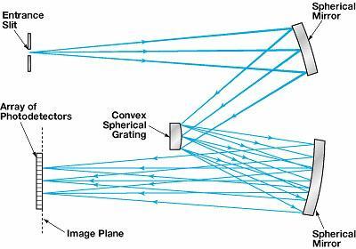
15 )2 $ )2 8 ˆ m)8 /d $ 8 /Nd Therefore the smallest possible )8 that can be resolved with a grating having N slits (grooves) is: 8/)8 = Nm R = 8/)8 is called the resolving power of the grating. Gratings are used in monochromators, spectrometers. These are instruments that are used to study the composition of light. Gratings can either work in transmission or reflection Specular reflection out Different wavelengths diffracted by different angles (only n=1 shown) White light in
16
: 2 = sin -1 (8/d).")
17 X-RAY DIFFRACTION X-rays are short wavelength E.M. waves: nm = m Can interference or diffraction be observed with such short wavelengths? Let s try to use a standard optical diffraction grating at these wavelengths. o Typical optical diffraction grating: d = 3:m o 8=0.1nm, o From the grating equation (assuming m = 1): 2 = sin -1 (8/d) o 2= basically means that the X-rays are not diffracted enough to be measurable. We need a better grating. To observe diffraction we need to have the spacing between the slits to be d. 8 How can we make a diffraction grating such that d = 0.1nm? We rely on nature: crystals are 3 dimensional gratings such that d m Where does the diffraction occur? In crystals X-rays get scattered by the atoms/molecules In some directions scattered x-rays interfere constructively Condition for constructive interference: dsinθ (local copy)
18 When 2dsinθ = m λ we get constructive interference. This equation is called Bragg s law. Note: o d is the spacing between atomic planes, not the spacing between atoms. It is called the inter-planar or lattice spacing o d depends on the crystallographic structure o Rotating the crystal, the beam will see different d o By measuring d we learn about the crystal structure o The symmetry of the crystal structure will be mirrored by the symmetry of the diffraction pattern o θ is the angle between incoming beam and the atomic planes, and not between the incoming beam and the normal to the planes (as is expected in optics) o x-ray diffraction is mainly used: o to study crystal structure o nowadays an important use is the study the structure of large biomolecules o The use of X-rays as an instrument for the systematic study of the way in which crystals are built was due to the William and Lawrence Bragg (father and son). They were recognized by the award of the Nobel Prize jointly in o An example of a x-ray diffraction from a silicon crystal is shown below (from /Silicon0556.gif&imgrefurl= &w=371&prev=/images%3fq%3dx-
")
19 ray%2bdiffraction%26start%3d20%26svnum%3d10%26hl%3den%26lr %3D%26ie%3DUTF-8%26oe%3DUTF-8%26sa%3DN) For a nice review of x-ray diffraction, see for example: (local copy)
20 Michelson s Interferometer Historical importance: o The Michelson interferometer is associated with experiments that lead to special relativity. These experiments by Michelson and Morley provided evidence against the existence of an absolute frame of reference (based on ether). (see for example, MorleyExperiment.html ) (local copy) o But Michelson's pioneering contributions to interferometry are much broader than just one experiment. He was awarded the Nobel Prize in 1907 for his many discoveries in optics. o The Michelson interferometer has become an indispensable tool in many scientific applications such as high-resolution spectroscopy, atomic length standards, and in practical applications, where displacements as small as a fraction of the wavelength of visible light must be measured. o We shall review the instrument that Michelson and Morley used. Interferometers are often used to measure very small distances but an interferogram can also be used to provide spectral information (see for example, ) (local copy) In the Michelson interferometer, light travels through 2 paths as shown in the diagram below Detector Light source (typically IR)
21 See for example, (local copy) Differences in the paths: )L = 2(D 1 - D 2 ) gives rise to phase difference between the waves: M = (2B /8))L Depending on the phase shift between the two beams travelling different paths, the interference between the waves can be constructive or destructive By moving one of the mirrors, the path difference changes, and so do the interference fringes from constructive to destructive or vice versa o By moving the mirror by ¼8 we go from a bright spot (constructive interference) to a dark spot (destructive interference) o By counting the number of dark - bright switches (fringes) we can measure distances in terms of 8
22 POLARIZATION o Light (EM radiation) is a transverse wave o One of the properties of a transverse wave is that it can be polarised. o This means that all the oscillations of the wave are in the same plane. o Light waves are electromagnetic waves, made up of electric and magnetic fields that oscillating perpendicular to each other. o When we talk about the oscillations of a light wave, we will be describing the oscillating electric field. (For clarity, the magnetic fields will not be shown. This is the normal practice when describing electromagnetic waves.) Electric field Direction of propagation o The plane containing the E and k vectors (k => direction of propagation) is called the plane of vibration o Since the electric (magnetic) fields are vector quantities they can be written as: where where (i,j,k) are the unit verctors E(x,t) = E z (x,t) + E y (x,t) E z (x,t) = ke oz cos(kx-ωt) E y (x,t) = je oy cos(kx-ωt+φ) o When Φ = 0, E z (x,t) and E y (x,t) are in phase, and the wave (light) is said to be linearly polarised:
23 (from (local copy) o When Φ 0, light is not linearly polarised. In the special case of Φ = π/2, and E oz = E oy (= E o ) light is circularly polarised: E z (x,t) = ke o cos(kx-ωt) E y (x,t) = je o cos(kx-ωt+π/2) = je o sin(kx-ωt) E(x,t) = E z (x,t) + E y (x,t) E(x,t) = ke o cos(kx-ωt) + je o sin(kx-ωt) E(x,t) = E o (kcos(kx-ωt) + jsin(kx-ωt)) o When we look at the beam head on, we ll see the tip of the E field rotate in a circle. For example, o when (kx-ωt) = 0, E(x,t) points in the z-direction: o at some other time, when (kx-ωt) = π/2 then E(x,t) points in the y- direction: o Therefore the tip of the electric field vector goes around in a circle! Hence circularly polarised light. Looking towards the source, the tip of the electric field rotates
24 from (local copy) o The vector can rotate clock-wise or anti clock-wise o Right-circularly polarised light and left c.p: R.C.P. E + (x,t) = ke oz cos(kx-ωt) + je oy sin(kx-ωt) L.C.P. E - (x,t) = ke oz cos(kx-ωt) - je oy sin(kx-ωt) o When we add a RCP and a LCP we get: E + (x,t) + E - (x,t) = 2kE oz cos(kx-ωt) <= linearly polarised light This was the case when Φ = π/2, and E oz = E oy (= E o ). What happens if Φ = π/2, but E oz E oy?
25 o When Φ = π/2, but E oz E oy light is called elliptically polarised. The tip of the electric field writes an ellipse: o When light is composed of a rapidly varying succession of different polarisations, we talk about unpolarised light. Sunlight is unpolarised. (NB. unpolarised light is not circularly polarised light): unpolarised light linearly polarised light Polarisers How can we make light oscillate in a certain direction? Polarisers do that.
26 Linear polariser o Instruments that produce well defined polarisation out of unpolarised light are called polarisers o Polarisers <=> analysers Linear polarisers Many types. We described some here: o Wire-grid type polarisers: light oscillating along the wire is absorbed, light oscillating perpendicular to the wires is not absorbed => transmitted light linearly polarised. Linearly polarised light Unpolarised light o OK for microwaves, IR or in general longer wavelengths o polaroid: similar to wire-grid but wires are molecules. OK for shorter wavelengths, eg. visible radiation (Invented in 1928 by Land, P/G student)
27 o Dichroic crystals: selective absorption of one direction of polarisation. Some crystalline materials absorb more light in one polarisation than in the other, so as light propagates through the material it becomes more and more polarised. This anisotropy in absorption is called dichroism. There are several naturally occurring dichroic materials. (The polaroid discussed above also polarises by selective absorption.) o Birefringence: in some crystals the refractive index depends on the direction of polarisation of light. So there are two refractive indexes depending on the polarisation: n o (ordinary) and n e (extraordinary). Since the r.i. are different, so is refraction: light will bend differently depending on the polarisation. These materials are anisotropic. In a birefringent material, light is split into two perpendicular polarizations with each being refracted slightly differently. Because they are refracted differently, the polarizations emerge in slightly different directions. Calcite is birefringent. (from ) (local copy)
28 o Polarisation by reflection: when unpolarised light is reflected from a dielectric, the reflected light is found to be partially polarised. o the degree of polarisation depends on the angle of incidence o at a special angle, called Brewster s angle, the reflected light is 100% polarised. Thus shining unpolarised light on a dielectric, we can get polarised light from the reflected component. (The transmitted light will only be partially polarised) o Brewster s angle occurs when ϑ i + ϑ t = 90 0 : (from ) (local copy) From Snell s law: (from ) (local copy)
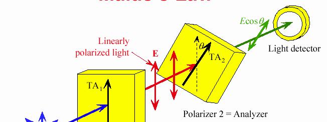
29 Note: o By measuring Brewster s angle we can determine the refractive index (for example, n 1 =1 (air), n 2 = 1.5 (glass) ϑ i = tan -1 (1.5) = 56 0 ) o Brewster windows often used in lasers o Polarisation by scattering: (From (local copy) o just like polarisation by reflection, polarisation by scattering produces linearly polarised light o air (other) molecules can be thought of as small antennas which reradiate perpendicular to their line of oscillation. o For example, the blue sky is (partially) polarised. How much light gets through a linear polariser? Malus s Law: I = I 0 cos 2 ϑ
30 (from
Phys102 Lecture Diffraction of Light
 Phys102 Lecture 31-33 Diffraction of Light Key Points Diffraction by a Single Slit Diffraction in the Double-Slit Experiment Limits of Resolution Diffraction Grating and Spectroscopy Polarization References
The science of light. P. Ewart
 The science of light P. Ewart Oxford Physics: Second Year, Optics Parallel reflecting surfaces t images source Extended source path difference xcos 2t=x Fringes localized at infinity Circular fringe constant
POLARISATION. We have not really discussed the direction of the Electric field other that that it is perpendicular to the direction of motion.
 POLARISATION Light is a transverse electromagnetic wave. We have not really discussed the direction of the Electric field other that that it is perpendicular to the direction of motion. If the E field
Lab #13: Polarization
 Lab #13: Polarization Introduction In this experiment we will investigate various properties associated with polarized light. We will study both its generation and application. Real world applications
UNIT-5 EM WAVES UNIT-6 RAY OPTICS
 UNIT-5 EM WAVES 2 Marks Question 1. To which regions of electromagnetic spectrum do the following wavelengths belong: (a) 250 nm (b) 1500 nm 2. State any one property which is common to all electromagnetic
LC circuit: Energy stored. This lecture reviews some but not all of the material that will be on the final exam that covers in Chapters
 Disclaimer: Chapter 29 Alternating-Current Circuits (1) This lecture reviews some but not all of the material that will be on the final exam that covers in Chapters 29-33. LC circuit: Energy stored LC
Lecture 9: Introduction to Diffraction of Light
 Lecture 9: Introduction to Diffraction of Light Lecture aims to explain: 1. Diffraction of waves in everyday life and applications 2. Interference of two one dimensional electromagnetic waves 3. Typical
Tutorial 7: Solutions
 Tutorial 7: Solutions 1. (a) A point source S is a perpendicular distance R away from the centre of a circular hole of radius a in an opaque screen. f the distance to the periphery is (R + l), show that
PS210 - Optical Techniques. Section VI
 PS210 - Optical Techniques Section VI Section I Light as Waves, Rays and Photons Section II Geometrical Optics & Optical Instrumentation Section III Periodic and Non-Periodic (Aperiodic) Waves Section
Light as a Transverse Wave.
 Waves and Superposition (Keating Chapter 21) The ray model for light (i.e. light travels in straight lines) can be used to explain a lot of phenomena (like basic object and image formation and even aberrations)
Einstein Classes, Unit No. 102, 103, Vardhman Ring Road Plaza, Vikas Puri Extn., Outer Ring Road New Delhi , Ph. : ,
 1 O P T I C S 1. Define resolving power of a telescope & microscope and give the expression for its resolving power. 2. Explain briefly the formation of mirage in deserts. 3. The radii of curvature of
Lecture 11: Introduction to diffraction of light
 Lecture 11: Introduction to diffraction of light Diffraction of waves in everyday life and applications Diffraction in everyday life Diffraction in applications Spectroscopy: physics, chemistry, medicine,
31. Diffraction: a few important illustrations
 31. Diffraction: a few important illustrations Babinet s Principle Diffraction gratings X-ray diffraction: Bragg scattering and crystal structures A lens transforms a Fresnel diffraction problem into a
OPSE FINAL EXAM Fall 2015 YOU MUST SHOW YOUR WORK. ANSWERS THAT ARE NOT JUSTIFIED WILL BE GIVEN ZERO CREDIT.
 CLOSED BOOK. Equation Sheet is provided. YOU MUST SHOW YOUR WORK. ANSWERS THAT ARE NOT JUSTIFIED WILL BE GIVEN ZERO CREDIT. ALL NUMERICAL ANSERS MUST HAVE UNITS INDICATED. (Except dimensionless units like
Engineering Physics 1 Prof. G.D. Vermaa Department of Physics Indian Institute of Technology-Roorkee
 Engineering Physics 1 Prof. G.D. Vermaa Department of Physics Indian Institute of Technology-Roorkee Module-04 Lecture-02 Diffraction Part - 02 In the previous lecture I discussed single slit and double
Physics I : Oscillations and Waves Prof. S. Bharadwaj Department of Physics and Meteorology Indian Institute of Technology, Kharagpur
 Physics I : Oscillations and Waves Prof. S. Bharadwaj Department of Physics and Meteorology Indian Institute of Technology, Kharagpur Lecture - 21 Diffraction-II Good morning. In the last class, we had
Get Discount Coupons for your Coaching institute and FREE Study Material at RAY OPTICS - I
 RAY OPTICS - I 1. Refraction of Light 2. Laws of Refraction 3. Principle of Reversibility of Light 4. Refraction through a Parallel Slab 5. Refraction through a Compound Slab 6. Apparent Depth of a Liquid
The EYE. Physics 1502: Lecture 32 Today s Agenda. Lecture 4. Announcements: Optics. Midterm 2: graded after Thanks Giving
 Physics 1502: Lecture 32 Today s Agenda Announcements: Midterm 2: graded after Thanks Giving Homework 09: Friday December 4 Optics Eye interference The EYE ~f o objective I 2 L I 1 ~f e eyepiece 1 2 Compound
Chiroptical Spectroscopy
 Chiroptical Spectroscopy Theory and Applications in Organic Chemistry Lecture 2: Polarized light Masters Level Class (181 041) Mondays, 8.15-9.45 am, NC 02/99 Wednesdays, 10.15-11.45 am, NC 02/99 28 Electromagnetic
Skoog Chapter 6 Introduction to Spectrometric Methods
 Skoog Chapter 6 Introduction to Spectrometric Methods General Properties of Electromagnetic Radiation (EM) Wave Properties of EM Quantum Mechanical Properties of EM Quantitative Aspects of Spectrochemical
PH 222-3A Spring 2010
 PH -3A Spring 010 Interference Lecture 6-7 Chapter 35 (Halliday/Resnick/Walker, Fundamentals of Physics 8 th edition) 1 Chapter 35 Interference The concept of optical interference is critical to understanding
Lecture PowerPoints. Chapter 24 Physics: Principles with Applications, 7 th edition Giancoli
 Lecture PowerPoints Chapter 24 Physics: Principles with Applications, 7 th edition Giancoli This work is protected by United States copyright laws and is provided solely for the use of instructors in teaching
: Imaging Systems Laboratory II. Laboratory 6: The Polarization of Light April 16 & 18, 2002
 151-232: Imaging Systems Laboratory II Laboratory 6: The Polarization of Light April 16 & 18, 22 Abstract. In this lab, we will investigate linear and circular polarization of light. Linearly polarized
Chapter 35. Interference
 Chapter 35 Interference The concept of optical interference is critical to understanding many natural phenomena, ranging from color shifting in butterfly wings to intensity patterns formed by small apertures.
PRINCIPLES OF PHYSICAL OPTICS
 PRINCIPLES OF PHYSICAL OPTICS C. A. Bennett University of North Carolina At Asheville WILEY- INTERSCIENCE A JOHN WILEY & SONS, INC., PUBLICATION CONTENTS Preface 1 The Physics of Waves 1 1.1 Introduction
Waves Part III Electromagnetic waves
 Waves Part III Electromagnetic waves Electromagnetic (light) waves Transverse waves Transport energy (and momentum) Can travel through vacuum (!) and certain solids, liquids and gases Do not transport
Optics Polarization. Lana Sheridan. June 20, De Anza College
 Optics Polarization Lana Sheridan De Anza College June 20, 2018 Last time interference from thin films Newton s rings Overview the interferometer and gravitational waves polarization birefringence 7 Michelson
Vågrörelselära och optik
 Vågrörelselära och optik Harmonic oscillation: Experiment Experiment to find a mathematical description of harmonic oscillation Kapitel 14 Harmonisk oscillator 1 2 Harmonic oscillation: Experiment Harmonic
Final Exam is coming!
 Final Exam is coming! Thurs., May 4, 4:30 to 6:30 pm, in this room. 25 multiple-choice questions Personalized exams I will enter the grade on your Mastering Physics account ( Final ). Old Part is comprehensive.
1. Waves and Particles 2. Interference of Waves 3. Wave Nature of Light
 1. Waves and Particles 2. Interference of Waves 3. Wave Nature of Light 1. Double-Slit Eperiment reading: Chapter 22 2. Single-Slit Diffraction reading: Chapter 22 3. Diffraction Grating reading: Chapter
Lecture 4: Diffraction & Spectroscopy
 Lecture 4: Diffraction & Spectroscopy d θ y L Spectra of atoms reveal the quantum nature of matter Take a plastic grating from the bin as you enter class. Lecture 4, p 1 Today s Topics Single-Slit Diffraction*
Polarization of Light and Birefringence of Materials
 Polarization of Light and Birefringence of Materials Ajit Balagopal (Team Members Karunanand Ogirala, Hui Shen) ECE 614- PHOTONIC INFORMATION PROCESSING LABORATORY Abstract-- In this project, we study
Lecture 4: Polarisation of light, introduction
 Lecture 4: Polarisation of light, introduction Lecture aims to explain: 1. Light as a transverse electro-magnetic wave 2. Importance of polarisation of light 3. Linearly polarised light 4. Natural light
Chapter 35 Diffraction and Polarization. Copyright 2009 Pearson Education, Inc.
 Chapter 35 Diffraction and Polarization 35-1 Diffraction by a Single Slit or Disk If light is a wave, it will diffract around a single slit or obstacle. 35-1 Diffraction by a Single Slit or Disk The resulting
Double Slit is VERY IMPORTANT because it is evidence of waves. Only waves interfere like this.
 Double Slit is VERY IMPORTANT because it is evidence of waves. Only waves interfere like this. Superposition of Sinusoidal Waves Assume two waves are traveling in the same direction, with the same frequency,
Light as Wave Motion p. 1 Huygens' Ideas p. 2 Newton's Ideas p. 8 Complex Numbers p. 10 Simple Harmonic Motion p. 11 Polarized Waves in a Stretched
 Introduction p. xvii Light as Wave Motion p. 1 Huygens' Ideas p. 2 Newton's Ideas p. 8 Complex Numbers p. 10 Simple Harmonic Motion p. 11 Polarized Waves in a Stretched String p. 16 Velocities of Mechanical
Light for which the orientation of the electric field is constant although its magnitude and sign vary in time.
 L e c t u r e 8 1 Polarization Polarized light Light for which the orientation of the electric field is constant although its magnitude and sign vary in time. Imagine two harmonic, linearly polarized light
Waves & Oscillations
 Physics 42200 Waves & Oscillations Lecture 32 Electromagnetic Waves Spring 2016 Semester Matthew Jones Electromagnetism Geometric optics overlooks the wave nature of light. Light inconsistent with longitudinal
Name Final Exam May 1, 2017
 Name Final Exam May 1, 217 This test consists of five parts. Please note that in parts II through V, you can skip one question of those offered. Some possibly useful formulas appear below. Constants, etc.
Physics 214 Course Overview
 Physics 214 Course Overview Lecturer: Mike Kagan Course topics Electromagnetic waves Optics Thin lenses Interference Diffraction Relativity Photons Matter waves Black Holes EM waves Intensity Polarization
Physics 142 Wave Optics 1 Page 1. Wave Optics 1. For every complex problem there is one solution that is simple, neat, and wrong. H.L.
 Physics 142 Wave Optics 1 Page 1 Wave Optics 1 For every complex problem there is one solution that is simple, neat, and wrong. H.L. Mencken Interference and diffraction of waves The essential characteristic
Diffraction I. Physics 2415 Lecture 37. Michael Fowler, UVa
 Diffraction I Physics 2415 Lecture 37 Michael Fowler, UVa Today s Topics Michelson s interferometer The Michelson Morley experiment Single-slit diffraction Eye of a fly Angular resolution Michelson Interferometer
Ground- and Space-Based Telescopes. Dr. Vithal Tilvi
 Ground- and Space-Based Telescopes Dr. Vithal Tilvi Telescopes and Instruments Astronomers use telescopes to gather light from distant objects and instruments to record the data Telescopes gather light
Chapter 35 Diffraction and Polarization
 Chapter 35 Diffraction and Polarization If light is a wave, it will diffract around a single slit or obstacle. The resulting pattern of light and dark stripes is called a diffraction pattern. This pattern
Waves Part 3: Superposition
 Waves Part 3: Superposition Last modified: 06/06/2017 Superposition Standing Waves Definition Standing Waves Summary Standing Waves on a String Standing Waves in a Pipe Standing Waves in a Pipe with One
Michelson Interferometer
 Michelson Interferometer Objective Determination of the wave length of the light of the helium-neon laser by means of Michelson interferometer subsectionprinciple and Task Light is made to produce interference
Physics I Keystone Institute Technology & Management Unit-II
 Un-polarized light Ordinary light is a collection of wave trains emitted by atoms or group of atoms with coherent time no longer than 10-8 second. Each wave train has different orientation and phase of
Revision Guide. Chapter 7 Quantum Behaviour
 Revision Guide Chapter 7 Quantum Behaviour Contents CONTENTS... 2 REVISION CHECKLIST... 3 REVISION NOTES... 4 QUANTUM BEHAVIOUR... 4 Random arrival of photons... 4 Photoelectric effect... 5 PHASE AN PHASORS...
Measurements in Optics for Civil Engineers
 Measurements in Optics for Civil Engineers I. FOCAL LENGTH OF LENSES The behavior of simplest optical devices can be described by the method of geometrical optics. For convex or converging and concave
Week 7: Interference
 Week 7: Interference Superposition: Till now we have mostly discusssed single waves. While discussing group velocity we did talk briefly about superposing more than one wave. We will now focus on superposition
 Optics. The refractive index of a material of a plain concave lens is 5/3, the radius of curvature is 0.3m. The focal length of the lens in air is ) 0.45 m ) 0.6 m 3) 0.75 m 4).0 m. The refractive index
 Name : Roll No. :.. Invigilator s Signature :.. CS/B.Tech/SEM-2/PH-201/2010 2010 ENGINEERING PHYSICS Time Allotted : 3 Hours Full Marks : 70 The figures in the margin indicate full marks. Candidates are
Wave Propagation in Uniaxial Media. Reflection and Transmission at Interfaces
 Lecture 5: Crystal Optics Outline 1 Homogeneous, Anisotropic Media 2 Crystals 3 Plane Waves in Anisotropic Media 4 Wave Propagation in Uniaxial Media 5 Reflection and Transmission at Interfaces Christoph
Chapter 1 - The Nature of Light
 David J. Starling Penn State Hazleton PHYS 214 Electromagnetic radiation comes in many forms, differing only in wavelength, frequency or energy. Electromagnetic radiation comes in many forms, differing
Telescopes (Chapter 6)
") Telescopes (Chapter 6) Based on Chapter 6 This material will be useful for understanding Chapters 7 and 10 on Our planetary system and Jovian planet systems Chapter 5 on Light will be useful for understanding
Telescopes (Chapter 6) Based on Chapter 6 This material will be useful for understanding Chapters 7 and 10 on Our planetary system and Jovian planet systems Chapter 5 on Light will be useful for understanding
Chapter 33. Electromagnetic Waves
 Chapter 33 Electromagnetic Waves Today s information age is based almost entirely on the physics of electromagnetic waves. The connection between electric and magnetic fields to produce light is own of
Waves Part 3B: Interference
 Waves Part 3B: Interference Last modified: 31/01/2018 Contents Links Interference Path Difference & Interference Light Young s Double Slit Experiment What Sort of Wave is Light? Michelson-Morley Experiment
EM Waves. From previous Lecture. This Lecture More on EM waves EM spectrum Polarization. Displacement currents Maxwell s equations EM Waves
 EM Waves This Lecture More on EM waves EM spectrum Polarization From previous Lecture Displacement currents Maxwell s equations EM Waves 1 Reminders on waves Traveling waves on a string along x obey the
Prac%ce Quiz 8. These are Q s from old quizzes. I do not guarantee that the Q s on this year s quiz will be the same, or even similar.
 Prac%ce Quiz 8 These are Q s from old quizzes. I do not guarantee that the Q s on this year s quiz will be the same, or even similar. A laser beam shines vertically upwards. What laser power is needed
JRE Group of Institutions ASSIGNMENT # 1 Special Theory of Relativity
 ASSIGNMENT # 1 Special Theory of Relativity 1. What was the objective of conducting the Michelson-Morley experiment? Describe the experiment. How is the negative result of the experiment interpreted? 2.
16. More About Polarization
 16. More About Polarization Polarization control Wave plates Circular polarizers Reflection & polarization Scattering & polarization Birefringent materials have more than one refractive index A special
WAVE OPTICS GENERAL. Fig.1a The electromagnetic spectrum
 WAVE OPTICS GENERAL - The ray optics cannot explain the results of the two following experimental situations: a) When passing by small openings or illuminating small obstacles, the light bends around borders
Lecture 5: Polarization. Polarized Light in the Universe. Descriptions of Polarized Light. Polarizers. Retarders. Outline
 Lecture 5: Polarization Outline 1 Polarized Light in the Universe 2 Descriptions of Polarized Light 3 Polarizers 4 Retarders Christoph U. Keller, Leiden University, keller@strw.leidenuniv.nl ATI 2016,
Experiment 6: Interferometers
 Experiment 6: Interferometers Nate Saffold nas2173@columbia.edu Office Hour: Mondays, 5:30PM-6:30PM @ Pupin 1216 INTRO TO EXPERIMENTAL PHYS-LAB 1493/1494/2699 NOTE: No labs and no lecture next week! Outline
The interference of waves
 The interference of waves In physics, interference is the addition (superposition) of two or more waves that results in a new wave pattern. The displacements of the waves add algebraically. Consider two
If the wavelength is larger than the aperture, the wave will spread out at a large angle. [Picture P445] . Distance l S
![If the wavelength is larger than the aperture, the wave will spread out at a large angle. [Picture P445] . Distance l S](/thumbs/77/76053670.jpg "If the wavelength is larger than the aperture, the wave will spread out at a large angle. [Picture P445] . Distance l S") Chapter 10 Diffraction 10.1 Preliminary Considerations Diffraction is a deviation of light from rectilinear propagation. t occurs whenever a portion of a wavefront is obstructed. Hecht; 11/8/010; 10-1
Chapter 10 Diffraction 10.1 Preliminary Considerations Diffraction is a deviation of light from rectilinear propagation. t occurs whenever a portion of a wavefront is obstructed. Hecht; 11/8/010; 10-1
September 14, Monday 4. Tools for Solar Observations-II
 September 14, Monday 4. Tools for Solar Observations-II Spectrographs. Measurements of the line shift. Spectrograph Most solar spectrographs use reflection gratings. a(sinα+sinβ) grating constant Blazed
Electromagnetic Waves. Chapter 33 (Halliday/Resnick/Walker, Fundamentals of Physics 8 th edition)
") PH 222-3A Spring 2007 Electromagnetic Waves Lecture 22 Chapter 33 (Halliday/Resnick/Walker, Fundamentals of Physics 8 th edition) 1 Chapter 33 Electromagnetic Waves Today s information age is based almost
PH 222-3A Spring 2007 Electromagnetic Waves Lecture 22 Chapter 33 (Halliday/Resnick/Walker, Fundamentals of Physics 8 th edition) 1 Chapter 33 Electromagnetic Waves Today s information age is based almost
Crash Course on Optics I & II. COST Action IC1101 OPTICWISE 4 th Training School
 Crash Course on Optics I & II COST Action IC1101 OPTICWISE 4 th Training School Introductory Concepts Fermat s principle Snell s law Total internal refraction Dispersion Aberrations Interference and Diffraction
Lecture 2: Interference
 Lecture 2: Interference l S 1 d S 2 Lecture 2, p.1 Today Interference of sound waves Two-slit interference Lecture 2, p.2 Review: Wave Summary The formula y x,t Acos kx t describes a harmonic plane wave
Laser Optics-II. ME 677: Laser Material Processing Instructor: Ramesh Singh 1
 Laser Optics-II 1 Outline Absorption Modes Irradiance Reflectivity/Absorption Absorption coefficient will vary with the same effects as the reflectivity For opaque materials: reflectivity = 1 - absorptivity
A) n L < 1.0 B) n L > 1.1 C) n L > 1.3 D) n L < 1.1 E) n L < 1.3
 n L < 1.0 B) n L > 1.1 C) n L > 1.3 D) n L < 1.1 E) n L < 1.3") 1. A beam of light passes from air into water. Which is necessarily true? A) The frequency is unchanged and the wavelength increases. B) The frequency is unchanged and the wavelength decreases. C) The
1. A beam of light passes from air into water. Which is necessarily true? A) The frequency is unchanged and the wavelength increases. B) The frequency is unchanged and the wavelength decreases. C) The
Polarised Light. Evan Sheridan, Chris Kervick, Tom Power October
 Polarised Light Evan Sheridan, Chris Kervick, Tom Power 11367741 October 22 2012 Abstract Properties of linear polarised light are investigated using Helium/Neon gas laser, polaroid,a silicon photodiode,a
polarisation of Light
 Basic concepts to understand polarisation of Light Polarization of Light Nature of light: light waves are transverse in nature i. e. the waves propagates in a direction perpendicular to the direction of
The individual electric and magnetic waves are in phase. The fields peak at the same position at the same time.
 1 Part 3: Otics 3.1: Electromagnetic Waves An electromagnetic wave (light wave) consists of oscillating electric and magnetic fields. The directions of the electric and magnetic fields are erendicular.
Astronomy. Optics and Telescopes
 Astronomy A. Dayle Hancock adhancock@wm.edu Small 239 Office hours: MTWR 10-11am Optics and Telescopes - Refraction, lenses and refracting telescopes - Mirrors and reflecting telescopes - Diffraction limit,
1/d o +1/d i =1/f. Chapter 24 Wave Optics. The Lens Equation. Diffraction Interference Polarization. The Nature of Light
 Chapter 24 Wave Optics Diffraction Interference Polarization 2F h o The Lens Equation 1/d o +1/d i =1/f F F O d o f d i h i Geometrical and Physical Optics Geometrical Optics: The study of optical phenomena
Chapter 36, example problems:
 Chapter 6, example problems: (6.0) Light wave with electric field E y (x, t) = E max sin [(.20 0 7 m ) x ω t] passes through a slit. First dark band at ±2.6 from the center of the diffraction pattern.
PH 222-2C Fall Electromagnetic Waves Lectures Chapter 33 (Halliday/Resnick/Walker, Fundamentals of Physics 8 th edition)
") PH 222-2C Fall 2012 Electromagnetic Waves Lectures 21-22 Chapter 33 (Halliday/Resnick/Walker, Fundamentals of Physics 8 th edition) 1 Chapter 33 Electromagnetic Waves Today s information age is based almost
PH 222-2C Fall 2012 Electromagnetic Waves Lectures 21-22 Chapter 33 (Halliday/Resnick/Walker, Fundamentals of Physics 8 th edition) 1 Chapter 33 Electromagnetic Waves Today s information age is based almost
A beam of coherent monochromatic light from a distant galaxy is used in an optics experiment on Earth.
 Waves_P2 [152 marks] A beam of coherent monochromatic light from a distant galaxy is used in an optics experiment on Earth. The beam is incident normally on a double slit. The distance between the slits
Optical Systems Program of Studies Version 1.0 April 2012
 Optical Systems Program of Studies Version 1.0 April 2012 Standard1 Essential Understand Optical experimental methodology, data analysis, interpretation, and presentation strategies Essential Understandings:
Polarized Light. Nikki Truss. Abstract:
 Polarized Light Nikki Truss 9369481 Abstract: In this experiment, the properties of linearly polarised light were examined. Malus Law was verified using the apparatus shown in Fig. 1. Reflectance of s-polarised
Telescopes: Portals of Discovery
 Telescopes: Portals of Discovery How do light and matter interact? Emission Absorption Transmission Transparent objects transmit light Opaque objects block (absorb) light Reflection or Scattering Reflection
LECTURE 11 ELECTROMAGNETIC WAVES & POLARIZATION. Instructor: Kazumi Tolich
 LECTURE 11 ELECTROMAGNETIC WAVES & POLARIZATION Instructor: Kazumi Tolich Lecture 11 2 25.5 Electromagnetic waves Induced fields Properties of electromagnetic waves Polarization Energy of electromagnetic
POLARIZATION FUNDAMENTAL OPTICS POLARIZATION STATES 1. CARTESIAN REPRESENTATION 2. CIRCULAR REPRESENTATION. Polarization. marketplace.idexop.
 POLARIZATION POLARIZATION STATS Four numbers are required to describe a single plane wave Fourier component traveling in the + z direction. These can be thought of as the amplitude and phase shift of the
NAWAB SHAH ALAM KHAN COLLEGE OF ENGINEERING & TECHNOLOGY UNIT II-a POLARISATION
 NAWAB SHAH ALAM KHAN COLLEGE OF ENGINEERING & TECHNOLOGY UNIT II-a 1 POLARISATION SYLLABUS :Polarization: Introduction, Malus s law, double refraction, Nicol prism, Quarter wave and half wave plates. 1.
Chapter 34. Electromagnetic Waves
 Chapter 34 Electromagnetic Waves The Goal of the Entire Course Maxwell s Equations: Maxwell s Equations James Clerk Maxwell 1831 1879 Scottish theoretical physicist Developed the electromagnetic theory
Prac%ce Quiz 8. These are Q s from old quizzes. I do not guarantee that the Q s on this year s quiz will be the same, or even similar.
 Prac%ce Quiz 8 These are Q s from old quizzes. I do not guarantee that the Q s on this year s quiz will be the same, or even similar. A laser beam shines vertically upwards. What laser power is needed
Brewster Angle and Total Internal Reflection
 Lecture 4: Polarization Outline 1 Polarized Light in the Universe 2 Brewster Angle and Total Internal Reflection 3 Descriptions of Polarized Light 4 Polarizers 5 Retarders Christoph U. Keller, Utrecht
Optical Instruments. Chapter 25. Simple Magnifier. Clicker 1. The Size of a Magnified Image. Angular Magnification 4/12/2011
 Optical Instruments Chapter 25 Optical Instruments Analysis generally involves the laws of reflection and refraction Analysis uses the procedures of geometric optics To explain certain phenomena, the wave
 Name : Roll No. :.... Invigilator s Signature :.. CS/B.Tech (NEW)/SEM-2/PH-201/2013 2013 PHYSICS - I Time Allotted : 3 Hours Full Marks : 70 The figures in the margin indicate full marks. Candidates are
Optics. n n. sin c. sin
 Optics Geometrical optics (model) Light-ray: extremely thin parallel light beam Using this model, the explanation of several optical phenomena can be given as the solution of simple geometric problems.
DELHI PUBLIC SCHOOL, BAHADURGARH Sample Paper 1 PHYSICS CLASS-XII Date- Duration:3hr
 SET: 1 General Instructions:- DELHI PUBLIC SCHOOL, BAHADURGARH Sample Paper 1 PHYSICS CLASS-XII Date- Duration:3hr All questions are compulsory. There are 30 questions in total. Questions 1 to 8 carry
OPSE FINAL EXAM Fall 2016 YOU MUST SHOW YOUR WORK. ANSWERS THAT ARE NOT JUSTIFIED WILL BE GIVEN ZERO CREDIT.
 CLOSED BOOK. Equation Sheet is provided. YOU MUST SHOW YOUR WORK. ANSWERS THAT ARE NOT JUSTIFIED WILL BE GIVEN ZERO CREDIT. ALL NUMERICAL ANSERS MUST HAVE UNITS INDICATED. (Except dimensionless units like
Outline of College Physics OpenStax Book
 Outline of College Physics OpenStax Book Taken from the online version of the book Dec. 27, 2017 18. Electric Charge and Electric Field 18.1. Static Electricity and Charge: Conservation of Charge Define
Indicate whether each statement is true or false by circling your answer. No explanation for your choice is required. Each answer is worth 3 points.
 Physics 5B FINAL EXAM Winter 2009 PART I (15 points): True/False Indicate whether each statement is true or false by circling your answer. No explanation for your choice is required. Each answer is worth
Physics 5B PRACTICE FINAL EXAM A Winter 2009
 Physics 5B PRACTICE FINAL EXAM A Winter 2009 INSTRUCTIONS: This is a closed book exam. You may consult four (twosided) 8 1/2" 11" sheets of paper of personal notes. However, you may not collaborate and/or
B.Tech. First Semester Examination Physics-1 (PHY-101F)
") B.Tech. First Semester Examination Physics-1 (PHY-101F) Note : Attempt FIVE questions in all taking least two questions from each Part. All questions carry equal marks Part-A Q. 1. (a) What are Newton's
B.Tech. First Semester Examination Physics-1 (PHY-101F) Note : Attempt FIVE questions in all taking least two questions from each Part. All questions carry equal marks Part-A Q. 1. (a) What are Newton's
The Diffraction Grating
 The Diffraction Grating If one extends the double slit to large number of slits very closely spaced, one gets what is called a diffraction grating. d sin θ. Maxima are still at d sin θ m = mλ, m = 0, 1,
1. In Young s double slit experiment, when the illumination is white light, the higherorder fringes are in color.
 TRUE-FALSE STATEMENTS: ELECTRICITY: 1. Electric field lines originate on negative charges. 2. The flux of the electric field over a closed surface is proportional to the net charge enclosed by the surface.