Automatic Control Systems, 9th Edition
|
|
|
- Rebecca Stokes
- 5 years ago
- Views:
Transcription
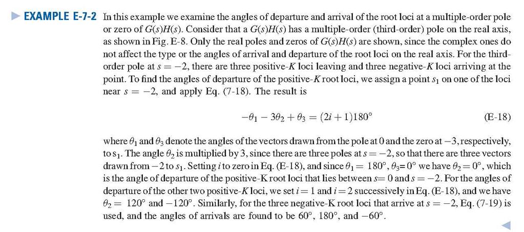
1 Chapter 7: Root Locus Analysis Appendix E: Properties and Construction of the Root Loci Automatic Control Systems, 9th Edition Farid Golnaraghi, Simon Fraser University Benjamin C. Kuo, University of Illinois ISBN:
2 Introduction In the preceding chapters, we have demonstrated the importance of the poles and zeros of the closedloop transfer function of a linear control system on the dynamic performance of the system. The roots of the characteristic equation, which are the poles of the closed-loop transfer function, determine the absolute and the relative stability of linear SISO systems. An important study in linear control systems is the investigation of the trajectories of the roots of the characteristic equation or, simply, the root loci when a certain system parameter varies.
3 The general root-locus problem can be formulated by referring to the following algebraic equation of the complex variable, say, s: 1. Root loci(rl). Refers to the entire root loci for - <K < Root contours(rc). Contour of roots when more than one parameter varies.
4 7-2 BASIC PROPERTIES OF THE ROOT LOCI (RL) The characteristic equation of the closed-loop system is obtained by setting the denominator polynomial of Y(s)/R(s) to zero. Suppose that G(s)H(s) contains a real variable parameter K as a multiplying factor, such that the rational function can be written as where P(s) and Q(s) are polynomials as defined in Eq. (7-2) and (7-3)
5 Let us express G(s)H(s) as where G 1 (s)h 1 (s) does not contain the variable parameter K. Condition on magnitude Condition on angles The conditions on angles in Eq. (7-14) or Eq. (7-15) are used to determine the trajectories of the root loci in the s-plane. Once the root loci are drawn, the values of K on the loci are determined by using the condition on magnitude in Eq. (7-13).
6 Condition on magnitude Condition on angles
7 For Positive K: Fig. 7-1 Pole-zero Configuration For negative K:
8 Fig. 7-2 Points at K=0 and k=±
9 7-3-2 NUMBER OF BRANCHES ON THE ROOT LOCI
10 7-3-3 Symmetry of the RL
11
12
13 7-3-5 Intersect of the Asymptotes (Centroid)
14
15
16 7-3-6 Root Loci on the Real Axis The entire real axis of the s-plane is occupied by the RL for all values K. On a given section of the real axis, RL for K 0 are found in the section only if the total number of poles and zeros of G(s)H(s) to the right of the section is odd. Note that the remaining sections of the real axis are occupied by the RL for K 0. Complex poles and zeros of G(s)H(s) do not affect the type of RL found on the real axis.
17 7-3-7 Angles of Departure and Angles of Arrival of the RL The angle of departure or arrival of a root locus at a pole or zero, respectively, of G(s)H(s) denotes the angle of the tangent to the locus near the point.
18
19
20 7-3-8 Intersection of the RL with the Imaginary Axis The points where the root loci intersect the imaginary axis of the s-plane, and the corresponding values of K, may be determined by means of the Routh-Hurwitz criterion. For complex situations, when the root loci have multiple number of intersections on the imaginary axis, the intersects and the critical values of K can be determined with the help of the root-locus computer program.
21 7-3-9 Breakaway Points (Saddle Points) on the RL
22 Breakaway Points (Saddle Points) on the RL This is a necessary but not a sufficient condition
23 E-9-2 The Angle of Arrival and Departure of Root Loci at the Breakaway Point The angles at which the root loci arrive or depart from a breakaway point depend on the number of loci that are involved at the point. For example, the root loci shown in Figs. E-9(a) and E-9(b) all arrive and break away at 180 apart, whereas in Fig. E-9(c), the four root loci arrive and depart with angles 90 apart, whereas in Fig. E-9(c), the four root loci arrive and depart with angles 90 apart. In general, n root loci (- K ) arrive or depart a breakaway point at 180/n degrees apart.
24
25
26
27
28
29
30
31
32
33
H(s) has the effect of pushing the root loci toward the right half")
34 7-4-1 Effects of Adding Poles and Zeros to G (s) H (s) Adding a pole to G(s)H(s) has the effect of pushing the root loci toward the right half s-plane.
 Adding left-half plane zeros to the")

35 7-4-1 Effects of Adding Poles and Zeros to G (s) H (s) Adding left-half plane zeros to the function G(s)H(s) generally has the effect of moving and bending the root loci toward the left-half s-plane.
36
37
38
39 Fig Root contours
40 Fig (a) RL (b) Pole-zero Configuration
41 Fig Root contours
42 Fig Root contours
43 Fig Root contours
44 Fig Root loci
45 Fig Pole-zero configuration
46 Fig Root contours
"APPENDIX. Properties and Construction of the Root Loci " E-1 K ¼ 0ANDK ¼1POINTS
 Appendix-E_1 5/14/29 1 "APPENDIX E Properties and Construction of the Root Loci The following properties of the root loci are useful for constructing the root loci manually and for understanding the root
7.4 STEP BY STEP PROCEDURE TO DRAW THE ROOT LOCUS DIAGRAM
 ROOT LOCUS TECHNIQUE. Values of on the root loci The value of at any point s on the root loci is determined from the following equation G( s) H( s) Product of lengths of vectors from poles of G( s)h( s)
CHAPTER # 9 ROOT LOCUS ANALYSES
 F K א CHAPTER # 9 ROOT LOCUS ANALYSES 1. Introduction The basic characteristic of the transient response of a closed-loop system is closely related to the location of the closed-loop poles. If the system
Control Systems Engineering ( Chapter 8. Root Locus Techniques ) Prof. Kwang-Chun Ho Tel: Fax:
 Prof. Kwang-Chun Ho Tel: Fax:") Control Systems Engineering ( Chapter 8. Root Locus Techniques ) Prof. Kwang-Chun Ho kwangho@hansung.ac.kr Tel: 02-760-4253 Fax:02-760-4435 Introduction In this lesson, you will learn the following : The
Control Systems Engineering ( Chapter 8. Root Locus Techniques ) Prof. Kwang-Chun Ho kwangho@hansung.ac.kr Tel: 02-760-4253 Fax:02-760-4435 Introduction In this lesson, you will learn the following : The
SECTION 5: ROOT LOCUS ANALYSIS
 SECTION 5: ROOT LOCUS ANALYSIS MAE 4421 Control of Aerospace & Mechanical Systems 2 Introduction Introduction 3 Consider a general feedback system: Closed loop transfer function is 1 is the forward path
Root locus Analysis. P.S. Gandhi Mechanical Engineering IIT Bombay. Acknowledgements: Mr Chaitanya, SYSCON 07
 Root locus Analysis P.S. Gandhi Mechanical Engineering IIT Bombay Acknowledgements: Mr Chaitanya, SYSCON 07 Recap R(t) + _ k p + k s d 1 s( s+ a) C(t) For the above system the closed loop transfer function
ECE 345 / ME 380 Introduction to Control Systems Lecture Notes 8
 Learning Objectives ECE 345 / ME 380 Introduction to Control Systems Lecture Notes 8 Dr. Oishi oishi@unm.edu November 2, 203 State the phase and gain properties of a root locus Sketch a root locus, by
Chapter 7 : Root Locus Technique
 Chapter 7 : Root Locus Technique By Electrical Engineering Department College of Engineering King Saud University 1431-143 7.1. Introduction 7.. Basics on the Root Loci 7.3. Characteristics of the Loci
I What is root locus. I System analysis via root locus. I How to plot root locus. Root locus (RL) I Uses the poles and zeros of the OL TF
 I Uses the poles and zeros of the OL TF") EE C28 / ME C34 Feedback Control Systems Lecture Chapter 8 Root Locus Techniques Lecture abstract Alexandre Bayen Department of Electrical Engineering & Computer Science University of California Berkeley
EE C28 / ME C34 Feedback Control Systems Lecture Chapter 8 Root Locus Techniques Lecture abstract Alexandre Bayen Department of Electrical Engineering & Computer Science University of California Berkeley
Software Engineering 3DX3. Slides 8: Root Locus Techniques
 Software Engineering 3DX3 Slides 8: Root Locus Techniques Dr. Ryan Leduc Department of Computing and Software McMaster University Material based on Control Systems Engineering by N. Nise. c 2006, 2007
Lecture 1 Root Locus
 Root Locus ELEC304-Alper Erdogan 1 1 Lecture 1 Root Locus What is Root-Locus? : A graphical representation of closed loop poles as a system parameter varied. Based on Root-Locus graph we can choose the
Chemical Process Dynamics and Control. Aisha Osman Mohamed Ahmed Department of Chemical Engineering Faculty of Engineering, Red Sea University
 Chemical Process Dynamics and Control Aisha Osman Mohamed Ahmed Department of Chemical Engineering Faculty of Engineering, Red Sea University 1 Chapter 4 System Stability 2 Chapter Objectives End of this
a. Closed-loop system; b. equivalent transfer function Then the CLTF () T is s the poles of () T are s from a contribution of a
 T is s the poles of () T are s from a contribution of a") Root Locus Simple definition Locus of points on the s- plane that represents the poles of a system as one or more parameter vary. RL and its relation to poles of a closed loop system RL and its relation
Root Locus Simple definition Locus of points on the s- plane that represents the poles of a system as one or more parameter vary. RL and its relation to poles of a closed loop system RL and its relation
Course roadmap. ME451: Control Systems. What is Root Locus? (Review) Characteristic equation & root locus. Lecture 18 Root locus: Sketch of proofs
 Characteristic equation & root locus. Lecture 18 Root locus: Sketch of proofs") ME451: Control Systems Modeling Course roadmap Analysis Design Lecture 18 Root locus: Sketch of proofs Dr. Jongeun Choi Department of Mechanical Engineering Michigan State University Laplace transform
ME451: Control Systems Modeling Course roadmap Analysis Design Lecture 18 Root locus: Sketch of proofs Dr. Jongeun Choi Department of Mechanical Engineering Michigan State University Laplace transform
Chapter 3: Block Diagrams and Signal Flow Graphs
 Chapter 3: Block Diagrams and Signal Flow Graphs Farid Golnaraghi, Simon Fraser University Benjamin C. Kuo, University of Illinois ISBN: 978 0 470 04896 2 Introduction In this chapter, we discuss graphical
Root Locus. Signals and Systems: 3C1 Control Systems Handout 3 Dr. David Corrigan Electronic and Electrical Engineering
 Root Locus Signals and Systems: 3C1 Control Systems Handout 3 Dr. David Corrigan Electronic and Electrical Engineering corrigad@tcd.ie Recall, the example of the PI controller car cruise control system.
Lecture 3: The Root Locus Method
 Lecture 3: The Root Locus Method Venkata Sonti Department of Mechanical Engineering Indian Institute of Science Bangalore, India, 56001 This draft: March 1, 008 1 The Root Locus method The Root Locus method,
Root locus 5. tw4 = 450. Root Locus S5-1 S O L U T I O N S
 Root Locus S5-1 S O L U T I O N S Root locus 5 Note: All references to Figures and Equations whose numbers are not preceded by an "S" refer to the textbook. (a) Rule 2 is all that is required to find the
SECTION 8: ROOT-LOCUS ANALYSIS. ESE 499 Feedback Control Systems
 SECTION 8: ROOT-LOCUS ANALYSIS ESE 499 Feedback Control Systems 2 Introduction Introduction 3 Consider a general feedback system: Closed-loop transfer function is KKKK ss TT ss = 1 + KKKK ss HH ss GG ss
Locus 6. More Root S 0 L U T I 0 N S. Note: All references to Figures and Equations whose numbers are not preceded by an "S"refer to the textbook.
 S 0 L U T I 0 N S More Root Locus 6 Note: All references to Figures and Equations whose numbers are not preceded by an "S"refer to the textbook. For the first transfer function a(s), the root locus is
Class 12 Root Locus part II
 Class 12 Root Locus part II Revising (from part I): Closed loop system K The Root Locus the locus of the poles of the closed loop system, when we vary the value of K Comple plane jω ais 0 real ais Thus,
Module 07 Control Systems Design & Analysis via Root-Locus Method
 Module 07 Control Systems Design & Analysis via Root-Locus Method Ahmad F. Taha EE 3413: Analysis and Desgin of Control Systems Email: ahmad.taha@utsa.edu Webpage: http://engineering.utsa.edu/ taha March
If you need more room, use the backs of the pages and indicate that you have done so.
 EE 343 Exam II Ahmad F. Taha Spring 206 Your Name: Your Signature: Exam duration: hour and 30 minutes. This exam is closed book, closed notes, closed laptops, closed phones, closed tablets, closed pretty
Introduction to Root Locus. What is root locus?
 Introduction to Root Locus What is root locus? A graphical representation of the closed loop poles as a system parameter (Gain K) is varied Method of analysis and design for stability and transient response
Root Locus Methods. The root locus procedure
 Root Locus Methods Design of a position control system using the root locus method Design of a phase lag compensator using the root locus method The root locus procedure To determine the value of the gain
Root Locus Techniques
 4th Edition E I G H T Root Locus Techniques SOLUTIONS TO CASE STUDIES CHALLENGES Antenna Control: Transient Design via Gain a. From the Chapter 5 Case Study Challenge: 76.39K G(s) = s(s+50)(s+.32) Since
Root Locus Techniques
 Root Locus Techniques 8 Chapter Learning Outcomes After completing this chapter the student will be able to: Define a root locus (Sections 8.1 8.2) State the properties of a root locus (Section 8.3) Sketch
School of Mechanical Engineering Purdue University. DC Motor Position Control The block diagram for position control of the servo table is given by:
 Root Locus Motivation Sketching Root Locus Examples ME375 Root Locus - 1 Servo Table Example DC Motor Position Control The block diagram for position control of the servo table is given by: θ D 0.09 See
Chapter 7. Root Locus Analysis
 Chapter 7 Root Locu Analyi jw + KGH ( ) GH ( ) - K 0 z O 4 p 2 p 3 p Root Locu Analyi The root of the cloed-loop characteritic equation define the ytem characteritic repone. Their location in the complex
Alireza Mousavi Brunel University
 Alireza Mousavi Brunel University 1 » Control Process» Control Systems Design & Analysis 2 Open-Loop Control: Is normally a simple switch on and switch off process, for example a light in a room is switched
Automatic Control Systems. Part III: Root Locus Technique
 www.pdhcenter.com PDH Coure E40 www.pdhonline.org Automatic Control Sytem Part III: Root Locu Technique By Shih-Min Hu, Ph.D., P.E. Page of 30 www.pdhcenter.com PDH Coure E40 www.pdhonline.org VI. Root
CONTROL SYSTEMS. Chapter 5 : Root Locus Diagram. GATE Objective & Numerical Type Solutions. The transfer function of a closed loop system is
 CONTROL SYSTEMS Chapter 5 : Root Locu Diagram GATE Objective & Numerical Type Solution Quetion 1 [Work Book] [GATE EC 199 IISc-Bangalore : Mark] The tranfer function of a cloed loop ytem i T () where i
CISE302: Linear Control Systems
 Term 8 CISE: Linear Control Sytem Dr. Samir Al-Amer Chapter 7: Root locu CISE_ch 7 Al-Amer8 ١ Learning Objective Undertand the concept of root locu and it role in control ytem deign Be able to ketch root
Test 2 SOLUTIONS. ENGI 5821: Control Systems I. March 15, 2010
 Test 2 SOLUTIONS ENGI 5821: Control Systems I March 15, 2010 Total marks: 20 Name: Student #: Answer each question in the space provided or on the back of a page with an indication of where to find the
EE302 - Feedback Systems Spring Lecture KG(s)H(s) = KG(s)
H(s) = KG(s)") EE3 - Feedback Systems Spring 19 Lecturer: Asst. Prof. M. Mert Ankarali Lecture 1.. 1.1 Root Locus In control theory, root locus analysis is a graphical analysis method for investigating the change of
EE3 - Feedback Systems Spring 19 Lecturer: Asst. Prof. M. Mert Ankarali Lecture 1.. 1.1 Root Locus In control theory, root locus analysis is a graphical analysis method for investigating the change of
Problems -X-O («) s-plane. s-plane *~8 -X -5. id) X s-plane. s-plane. -* Xtg) FIGURE P8.1. j-plane. JO) k JO)
 s-plane. s-plane *~8 -X -5. id) X s-plane. s-plane. -* Xtg) FIGURE P8.1. j-plane. JO) k JO)") Problems 1. For each of the root loci shown in Figure P8.1, tell whether or not the sketch can be a root locus. If the sketch cannot be a root locus, explain why. Give all reasons. [Section: 8.4] *~8 -X-O
Problems 1. For each of the root loci shown in Figure P8.1, tell whether or not the sketch can be a root locus. If the sketch cannot be a root locus, explain why. Give all reasons. [Section: 8.4] *~8 -X-O
Methods for analysis and control of. Lecture 4: The root locus design method
 Methods for analysis and control of Lecture 4: The root locus design method O. Sename 1 1 Gipsa-lab, CNRS-INPG, FRANCE Olivier.Sename@gipsa-lab.inpg.fr www.lag.ensieg.inpg.fr/sename Lead Lag 17th March
Some special cases
 Lecture Notes on Control Systems/D. Ghose/2012 87 11.3.1 Some special cases Routh table is easy to form in most cases, but there could be some cases when we need to do some extra work. Case 1: The first
Methods for analysis and control of dynamical systems Lecture 4: The root locus design method
 Methods for analysis and control of Lecture 4: The root locus design method O. Sename 1 1 Gipsa-lab, CNRS-INPG, FRANCE Olivier.Sename@gipsa-lab.inpg.fr www.gipsa-lab.fr/ o.sename 5th February 2015 Outline
Controls Problems for Qualifying Exam - Spring 2014
 Controls Problems for Qualifying Exam - Spring 2014 Problem 1 Consider the system block diagram given in Figure 1. Find the overall transfer function T(s) = C(s)/R(s). Note that this transfer function
Lecture 12: Examples of Root Locus Plots. Dr. Kalyana Veluvolu. Lecture 12: Examples of Root Locus Plots Dr. Kalyana Veluvolu
 ROOT-LOCUS ANALYSIS Example: Given that G( ) ( + )( + ) Dr. alyana Veluvolu Sketch the root locu of 1 + G() and compute the value of that will yield a dominant econd order behavior with a damping ratio,
ROOT LOCUS. Consider the system. Root locus presents the poles of the closed-loop system when the gain K changes from 0 to. H(s) H ( s) = ( s)
 H ( s) = ( s)") C1 ROOT LOCUS Consider the system R(s) E(s) C(s) + K G(s) - H(s) C(s) R(s) = K G(s) 1 + K G(s) H(s) Root locus presents the poles of the closed-loop system when the gain K changes from 0 to 1+ K G ( s)
C1 ROOT LOCUS Consider the system R(s) E(s) C(s) + K G(s) - H(s) C(s) R(s) = K G(s) 1 + K G(s) H(s) Root locus presents the poles of the closed-loop system when the gain K changes from 0 to 1+ K G ( s)
CHAPTER 1 Basic Concepts of Control System. CHAPTER 6 Hydraulic Control System
 CHAPTER 1 Basic Concepts of Control System 1. What is open loop control systems and closed loop control systems? Compare open loop control system with closed loop control system. Write down major advantages
5 Root Locus Analysis
 5 Root Locus Analysis 5.1 Introduction A control system is designed in tenns of the perfonnance measures discussed in chapter 3. Therefore, transient response of a system plays an important role in the
Appendix A Complex Variable Theory
 Appendix A Complex Variable Theory TO ACCOMPANY AUTOMATIC CONTROL SYSTEMS EIGHTH EDITION BY BENJAMIN C. KUO FARID GOLNARAGHI JOHN WILEY & SONS, INC. Copyright 2003 John Wiley & Sons, Inc. All rights reserved.
Example on Root Locus Sketching and Control Design
 Example on Root Locus Sketching and Control Design MCE44 - Spring 5 Dr. Richter April 25, 25 The following figure represents the system used for controlling the robotic manipulator of a Mars Rover. We
FEEDBACK and CONTROL SYSTEMS
 SCHA UM'S OUTLINE OF THEORY AND PROBLEMS OF FEEDBACK and CONTROL SYSTEMS Second Edition CONTINUOUS (ANALOG) AND DISCRETE (DIGITAL) JOSEPH J. DiSTEFANO, III, PhD. Departments of Computer Science and Mediane
Root Locus Diagram. Root loci: The portion of root locus when k assume positive values: that is 0
 Objective Root Locu Diagram Upon completion of thi chapter you will be able to: Plot the Root Locu for a given Tranfer Function by varying gain of the ytem, Analye the tability of the ytem from the root
2.004 Dynamics and Control II Spring 2008
 MT OpenCourseWare http://ocw.mit.edu.004 Dynamics and Control Spring 008 For information about citing these materials or our Terms of Use, visit: http://ocw.mit.edu/terms. Massachusetts nstitute of Technology
Block Diagram Reduction
 Block Diagram Reduction Figure 1: Single block diagram representation Figure 2: Components of Linear Time Invariant Systems (LTIS) Figure 3: Block diagram components Figure 4: Block diagram of a closed-loop
ECE317 : Feedback and Control
 ECE317 : Feedback and Control Lecture : Routh-Hurwitz stability criterion Examples Dr. Richard Tymerski Dept. of Electrical and Computer Engineering Portland State University 1 Course roadmap Modeling
Step input, ramp input, parabolic input and impulse input signals. 2. What is the initial slope of a step response of a first order system?
 IC6501 CONTROL SYSTEM UNIT-II TIME RESPONSE PART-A 1. What are the standard test signals employed for time domain studies?(or) List the standard test signals used in analysis of control systems? (April
Root Locus U R K. Root Locus: Find the roots of the closed-loop system for 0 < k < infinity
 Background: Root Locus Routh Criteria tells you the range of gains that result in a stable system. It doesn't tell you how the system will behave, however. That's a problem. For example, for the following
Unit 7: Part 1: Sketching the Root Locus
 Root Locus Unit 7: Part 1: Sketching the Root Locus Engineering 5821: Control Systems I Faculty of Engineering & Applied Science Memorial University of Newfoundland March 14, 2010 ENGI 5821 Unit 7: Root
ECEN 605 LINEAR SYSTEMS. Lecture 20 Characteristics of Feedback Control Systems II Feedback and Stability 1/27
 1/27 ECEN 605 LINEAR SYSTEMS Lecture 20 Characteristics of Feedback Control Systems II Feedback and Stability Feedback System Consider the feedback system u + G ol (s) y Figure 1: A unity feedback system
Remember that : Definition :
 Stability This lecture we will concentrate on How to determine the stability of a system represented as a transfer function How to determine the stability of a system represented in state-space How to
Automatic Control (TSRT15): Lecture 4
: Lecture 4") Automatic Control (TSRT15): Lecture 4 Tianshi Chen Division of Automatic Control Dept. of Electrical Engineering Email: tschen@isy.liu.se Phone: 13-282226 Office: B-house extrance 25-27 Review of the last
Automatic Control (TSRT15): Lecture 4 Tianshi Chen Division of Automatic Control Dept. of Electrical Engineering Email: tschen@isy.liu.se Phone: 13-282226 Office: B-house extrance 25-27 Review of the last
6.302 Feedback Systems Recitation 7: Root Locus Prof. Joel L. Dawson
 To start with, let s mae sure we re clear on exactly what we mean by the words root locus plot. Webster can help us with this: ROOT: A number that reduces and equation to an identity when it is substituted
MAK 391 System Dynamics & Control. Presentation Topic. The Root Locus Method. Student Number: Group: I-B. Name & Surname: Göksel CANSEVEN
 MAK 391 System Dynamics & Control Presentation Topic The Root Locus Method Student Number: 9901.06047 Group: I-B Name & Surname: Göksel CANSEVEN Date: December 2001 The Root-Locus Method Göksel CANSEVEN
Välkomna till TSRT15 Reglerteknik Föreläsning 4. Summary of lecture 3 Root locus More specifications Zeros (if there is time)
") Välkomna till TSRT15 Reglerteknik Föreläsning 4 Summary of lecture 3 Root locus More specifications Zeros (if there is time) Summary of last lecture 2 We introduced the PID-controller (Proportional Integrating
Välkomna till TSRT15 Reglerteknik Föreläsning 4 Summary of lecture 3 Root locus More specifications Zeros (if there is time) Summary of last lecture 2 We introduced the PID-controller (Proportional Integrating
KINGS COLLEGE OF ENGINEERING DEPARTMENT OF ELECTRONICS AND COMMUNICATION ENGINEERING
 KINGS COLLEGE OF ENGINEERING DEPARTMENT OF ELECTRONICS AND COMMUNICATION ENGINEERING QUESTION BANK SUB.NAME : CONTROL SYSTEMS BRANCH : ECE YEAR : II SEMESTER: IV 1. What is control system? 2. Define open
Control Systems Engineering ( Chapter 6. Stability ) Prof. Kwang-Chun Ho Tel: Fax:
 Prof. Kwang-Chun Ho Tel: Fax:") Control Systems Engineering ( Chapter 6. Stability ) Prof. Kwang-Chun Ho kwangho@hansung.ac.kr Tel: 02-760-4253 Fax:02-760-4435 Introduction In this lesson, you will learn the following : How to determine
Control Systems Engineering ( Chapter 6. Stability ) Prof. Kwang-Chun Ho kwangho@hansung.ac.kr Tel: 02-760-4253 Fax:02-760-4435 Introduction In this lesson, you will learn the following : How to determine
Software Engineering/Mechatronics 3DX4. Slides 6: Stability
 Software Engineering/Mechatronics 3DX4 Slides 6: Stability Dr. Ryan Leduc Department of Computing and Software McMaster University Material based on lecture notes by P. Taylor and M. Lawford, and Control
Dominant Pole Localization of FxLMS Adaptation Process in Active Noise Control
 APSIPA ASC 20 Xi an Dominant Pole Localization of FxLMS Adaptation Process in Active Noise Control Iman Tabatabaei Ardekani, Waleed H. Abdulla The University of Auckland, Private Bag 9209, Auckland, New
Unit 7: Part 1: Sketching the Root Locus. Root Locus. Vector Representation of Complex Numbers
 Root Locus Root Locus Unit 7: Part 1: Sketching the Root Locus Engineering 5821: Control Systems I Faculty of Engineering & Applied Science Memorial University of Newfoundland 1 Root Locus Vector Representation
Course Summary. The course cannot be summarized in one lecture.
 Course Summary Unit 1: Introduction Unit 2: Modeling in the Frequency Domain Unit 3: Time Response Unit 4: Block Diagram Reduction Unit 5: Stability Unit 6: Steady-State Error Unit 7: Root Locus Techniques
2.004 Dynamics and Control II Spring 2008
 MT OpenCourseWare http://ocw.mit.edu 2.004 Dynamics and Control Spring 2008 or information about citing these materials or our Terms of Use, visit: http://ocw.mit.edu/terms. Reading: ise: Chapter 8 Massachusetts
MODERN CONTROL SYSTEMS
 MODERN CONTROL SYSTEMS Lecture 1 Root Locu Emam Fathy Department of Electrical and Control Engineering email: emfmz@aat.edu http://www.aat.edu/cv.php?dip_unit=346&er=68525 1 Introduction What i root locu?
EXAMPLE PROBLEMS AND SOLUTIONS
 Similarly, the program for the fourth-order transfer function approximation with T = 0.1 sec is [num,denl = pade(0.1, 4); printsys(num, den, 'st) numlden = sa4-2o0sa3 + 1 80O0sA2-840000~ + 16800000 sa4
and a where is a Vc. K val paran This ( suitab value
 198 Chapter 5 Root-Locus Method One classical technique in determining pole variations with parameters is known as the root-locus method, invented by W. R. Evens, which will be introduced in this chapter.
EE Control Systems LECTURE 14
 Updated: Tueday, March 3, 999 EE 434 - Control Sytem LECTURE 4 Copyright FL Lewi 999 All right reerved ROOT LOCUS DESIGN TECHNIQUE Suppoe the cloed-loop tranfer function depend on a deign parameter k We
(b) A unity feedback system is characterized by the transfer function. Design a suitable compensator to meet the following specifications:
 A unity feedback system is characterized by the transfer function. Design a suitable compensator to meet the following specifications:") 1. (a) The open loop transfer function of a unity feedback control system is given by G(S) = K/S(1+0.1S)(1+S) (i) Determine the value of K so that the resonance peak M r of the system is equal to 1.4.
1. (a) The open loop transfer function of a unity feedback control system is given by G(S) = K/S(1+0.1S)(1+S) (i) Determine the value of K so that the resonance peak M r of the system is equal to 1.4.
Control Systems I. Lecture 7: Feedback and the Root Locus method. Readings: Jacopo Tani. Institute for Dynamic Systems and Control D-MAVT ETH Zürich
 Control Systems I Lecture 7: Feedback and the Root Locus method Readings: Jacopo Tani Institute for Dynamic Systems and Control D-MAVT ETH Zürich November 2, 2018 J. Tani, E. Frazzoli (ETH) Lecture 7:
CONTROL * ~ SYSTEMS ENGINEERING
 CONTROL * ~ SYSTEMS ENGINEERING H Fourth Edition NormanS. Nise California State Polytechnic University, Pomona JOHN WILEY& SONS, INC. Contents 1. Introduction 1 1.1 Introduction, 2 1.2 A History of Control
Module 3F2: Systems and Control EXAMPLES PAPER 2 ROOT-LOCUS. Solutions
 Cambridge University Engineering Dept. Third Year Module 3F: Systems and Control EXAMPLES PAPER ROOT-LOCUS Solutions. (a) For the system L(s) = (s + a)(s + b) (a, b both real) show that the root-locus
Analysis of SISO Control Loops
 Chapter 5 Analysis of SISO Control Loops Topics to be covered For a given controller and plant connected in feedback we ask and answer the following questions: Is the loop stable? What are the sensitivities
ME2142/ME2142E Feedback Control Systems
 Root Locu Analyi Root Locu Analyi Conider the cloed-loop ytem R + E - G C B H The tranient repone, and tability, of the cloed-loop ytem i determined by the value of the root of the characteritic equation
Outline. Control systems. Lecture-4 Stability. V. Sankaranarayanan. V. Sankaranarayanan Control system
 Outline Control systems Lecture-4 Stability V. Sankaranarayanan Outline Outline 1 Outline Outline 1 2 Concept of Stability Zero State Response: The zero-state response is due to the input only; all the
Control Systems. Frequency Method Nyquist Analysis.
 Frequency Method Nyquist Analysis chibum@seoultech.ac.kr Outline Polar plots Nyquist plots Factors of polar plots PolarNyquist Plots Polar plot: he locus of the magnitude of ω vs. the phase of ω on polar
Class 11 Root Locus part I
 Class 11 Root Locus part I Closed loop system G(s) G(s) G(s) Closed loop system K The Root Locus the locus of the poles of the closed loop system, when we vary the value of K We shall assume here K >,
Root Locus. 1 Review of related mathematics. Ang Man Shun. October 30, Complex Algebra in Polar Form. 1.2 Roots of a equation
 Root Locus Ang Man Shun October 3, 212 1 Review of relate mathematics 1.1 Complex Algebra in Polar Form For a complex number z, it can be expresse in polar form as z = re jθ 1 Im z Where r = z, θ = tan.
ECE 486 Control Systems
 ECE 486 Control Systems Spring 208 Midterm #2 Information Issued: April 5, 208 Updated: April 8, 208 ˆ This document is an info sheet about the second exam of ECE 486, Spring 208. ˆ Please read the following
STABILITY OF CLOSED-LOOP CONTOL SYSTEMS
 CHBE320 LECTURE X STABILITY OF CLOSED-LOOP CONTOL SYSTEMS Professor Dae Ryook Yang Spring 2018 Dept. of Chemical and Biological Engineering 10-1 Road Map of the Lecture X Stability of closed-loop control
HANDOUT E.22 - EXAMPLES ON STABILITY ANALYSIS
 Example 1 HANDOUT E. - EXAMPLES ON STABILITY ANALYSIS Determine the stability of the system whose characteristics equation given by 6 3 = s + s + 3s + s + s + s +. The above polynomial satisfies the necessary
Stability Analysis Techniques
 Stability Analysis Techniques In this section the stability analysis techniques for the Linear Time-Invarient (LTI) discrete system are emphasized. In general the stability techniques applicable to LTI
INSTITUTE OF AERONAUTICAL ENGINEERING (Autonomous) Dundigal, Hyderabad
 Dundigal, Hyderabad") INSTITUTE OF AERONAUTICAL ENGINEERING (Autonomous) Dundigal, Hyderabad - 500 043 Electrical and Electronics Engineering TUTORIAL QUESTION BAN Course Name : CONTROL SYSTEMS Course Code : A502 Class : III
INSTITUTE OF AERONAUTICAL ENGINEERING (Autonomous) Dundigal, Hyderabad - 500 043 Electrical and Electronics Engineering TUTORIAL QUESTION BAN Course Name : CONTROL SYSTEMS Course Code : A502 Class : III
Department of Mathematics, University of Wisconsin-Madison Math 114 Worksheet Sections (4.1),
,") Department of Mathematics, University of Wisconsin-Madison Math 114 Worksheet Sections (4.1), 4.-4.6 1. Find the polynomial function with zeros: -1 (multiplicity ) and 1 (multiplicity ) whose graph passes
Department of Mathematics, University of Wisconsin-Madison Math 114 Worksheet Sections (4.1), 4.-4.6 1. Find the polynomial function with zeros: -1 (multiplicity ) and 1 (multiplicity ) whose graph passes
EC CONTROL SYSTEM UNIT I- CONTROL SYSTEM MODELING
 EC 2255 - CONTROL SYSTEM UNIT I- CONTROL SYSTEM MODELING 1. What is meant by a system? It is an arrangement of physical components related in such a manner as to form an entire unit. 2. List the two types
Dr Ian R. Manchester Dr Ian R. Manchester AMME 3500 : Root Locus
 Week Content Notes 1 Introduction 2 Frequency Domain Modelling 3 Transient Performance and the s-plane 4 Block Diagrams 5 Feedback System Characteristics Assign 1 Due 6 Root Locus 7 Root Locus 2 Assign
Compensation 8. f4 that separate these regions of stability and instability. The characteristic S 0 L U T I 0 N S
 S 0 L U T I 0 N S Compensation 8 Note: All references to Figures and Equations whose numbers are not preceded by an "S"refer to the textbook. As suggested in Lecture 8, to perform a Nyquist analysis, we
ROOT LOCUS. Poles and Zeros
 Automatic Control Sytem, 343 Deartment of Mechatronic Engineering, German Jordanian Univerity ROOT LOCUS The Root Locu i the ath of the root of the characteritic equation traced out in the - lane a a ytem
Solving Linear and Rational Inequalities Algebraically. Definition 22.1 Two inequalities are equivalent if they have the same solution set.
 Inequalities Concepts: Equivalent Inequalities Solving Linear and Rational Inequalities Algebraically Approximating Solutions to Inequalities Graphically (Section 4.4).1 Equivalent Inequalities Definition.1
INSTITUTE OF AERONAUTICAL ENGINEERING Dundigal, Hyderabad ELECTRICAL AND ELECTRONICS ENGINEERING TUTORIAL QUESTION BANK
 Course Name Course Code Class Branch INSTITUTE OF AERONAUTICAL ENGINEERING Dundigal, Hyderabad -500 043 ELECTRICAL AND ELECTRONICS ENGINEERING TUTORIAL QUESTION BAN : CONTROL SYSTEMS : A50 : III B. Tech
Homework 11 Solution - AME 30315, Spring 2015
 1 Homework 11 Solution - AME 30315, Spring 2015 Problem 1 [10/10 pts] R + - K G(s) Y Gpsq Θpsq{Ipsq and we are interested in the closed-loop pole locations as the parameter k is varied. Θpsq Ipsq k ωn
Control Systems. Root locus.
 Control Sytem Root locu chibum@eoultech.ac.kr Outline Concet of Root Locu Contructing root locu Control Sytem Root Locu Stability and tranient reone i cloely related with the location of ole in -lane How
EE 370L Controls Laboratory. Laboratory Exercise #7 Root Locus. Department of Electrical and Computer Engineering University of Nevada, at Las Vegas
 EE 370L Controls Laboratory Laboratory Exercise #7 Root Locus Department of Electrical an Computer Engineering University of Nevaa, at Las Vegas 1. Learning Objectives To emonstrate the concept of error
Control Systems. University Questions
 University Questions UNIT-1 1. Distinguish between open loop and closed loop control system. Describe two examples for each. (10 Marks), Jan 2009, June 12, Dec 11,July 08, July 2009, Dec 2010 2. Write
Automatic Control Systems theory overview (discrete time systems)
") Automatic Control Systems theory overview (discrete time systems) Prof. Luca Bascetta (luca.bascetta@polimi.it) Politecnico di Milano Dipartimento di Elettronica, Informazione e Bioingegneria Motivations
Automatic Control Systems theory overview (discrete time systems) Prof. Luca Bascetta (luca.bascetta@polimi.it) Politecnico di Milano Dipartimento di Elettronica, Informazione e Bioingegneria Motivations
Lecture Sketching the root locus
 Lecture 05.02 Sketching the root locus It is easy to get lost in the detailed rules of manual root locus construction. In the old days accurate root locus construction was critical, but now it is useful
The Nyquist criterion relates the stability of a closed system to the open-loop frequency response and open loop pole location.
 Introduction to the Nyquist criterion The Nyquist criterion relates the stability of a closed system to the open-loop frequency response and open loop pole location. Mapping. If we take a complex number