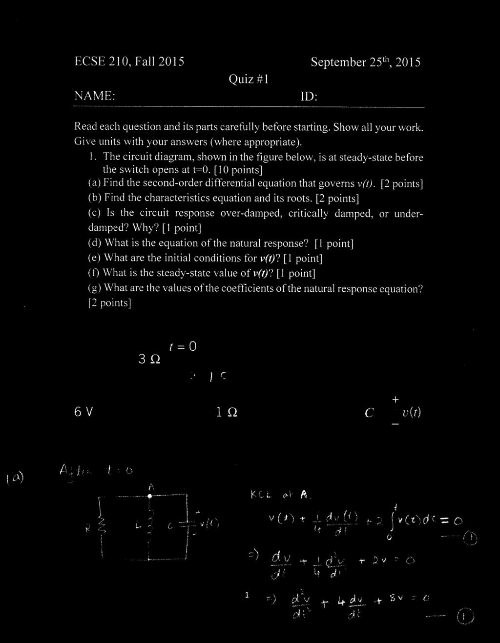
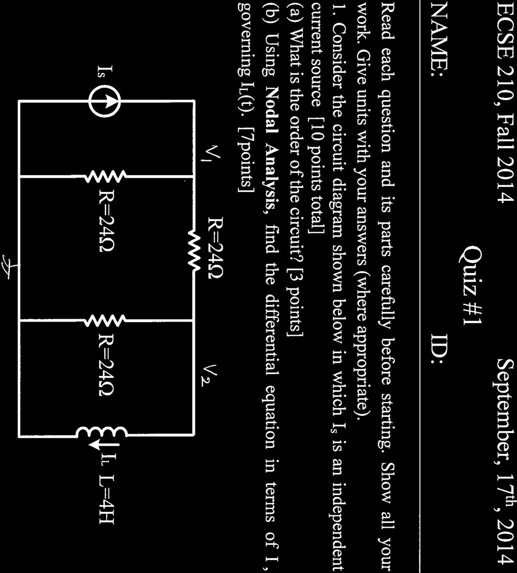
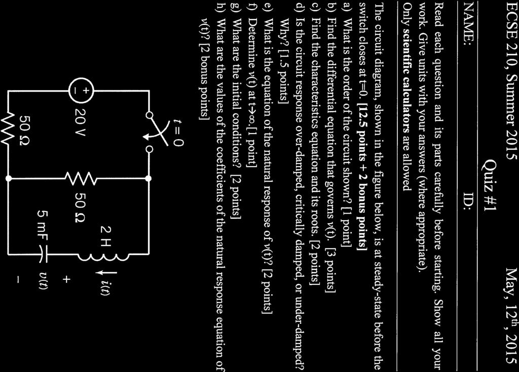
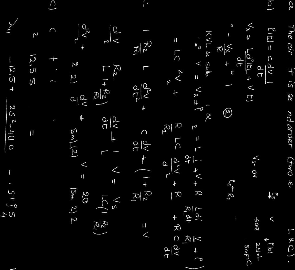
Read each question and its parts carefully before starting. Show all your work. Give units with your answers (where appropriate).
|
|
|
- Rebecca McKinney
- 5 years ago
- Views:
Transcription
1
2
3
4 ECSE 10, Fall 013 NAME: Quiz #1 September 17, 013 ID: Read each question and its parts carefully before starting. Show all your work. Give units with your answers (where appropriate). 1. Consider the circuit diagram below. The switch is opened at t = 0 after having been closed for a long time. [10pt] (a) Find the second-order differential equation governing v 1 (t) for t 0. [4pt] (b) Is the circuit over damped, critically damped, or under damped? Why? [1pt] (c) Determine v 1 (t) for t 0.[5pt] t=0 4V 1 H 1 F v 1 - _ 5i 1 / 8 Ω i 3 Ω Solution: t=0 1 4V i 1 H i1 1 F v 1 - _ 5i 1 / 8 Ω i 3 Ω 1
5 ECSE 10, Fall 013 NAME: Quiz #1 September 17, 013 ID: Applying KCL at node 1: v 1 = di 1 8 i The characteristic equation: i i 1 i = 0 i = v 1 5i 3 i 1 = dv 1 i = v 1 i = v 1 dv 1 d v dv v 1 = 0 [4pt] λ 3 8 λ = 0 λ 1, λ = ± j 16 Roots of the characteristic equation are two complex numbers, therefore the system is under damped. [1pt] ) v 1 (t) = e (A t cos 16 t B sin 16 t [1pt] Initial Conditions: [pt] v 1 (0 ) = v 1 (0 ) = 4V i (0 ) = i (0 ) = 3A v 1 (0 ) dv 1 (0 ) = i (0 ) Applying initial conditions: dv 1 (0 ) = 30 v 1 (t) = e (4 t cos A = 4 B = t sin 77 ) t [pt]
6 ECSE 10, Fall 013 NAME: Quiz #1 September 17, 013 ID: Read each question and its parts carefully before starting. Show all your work. Give units with your answers (where appropriate). 1. Consider the circuit diagram below. The switch is opened at t = 0 after having been closed for a long time. [10pt] (a) Find the second-order differential equation governing v 1 (t) for t 0. [4pt] (b) Is the circuit over damped, critically damped, or under damped? Why? [1pt] (c) Determine v 1 (t) for t 0.[5pt] t=0 4V 1 H 1 F v 1 - _ 5i 1 / 8 Ω i 3 Ω Solution: t=0 1 4V i 1 H i1 1 F v 1 - _ 5i 1 / 8 Ω i 3 Ω 1
7 ECSE 10, Fall 013 NAME: Quiz #1 September 17, 013 ID: Applying KCL at node 1: v 1 = di 1 8 i The characteristic equation: i i 1 i = 0 i = v 1 5i 3 i 1 = dv 1 i = v 1 i = v 1 dv 1 d v dv v 1 = 0 [4pt] λ 3 8 λ = 0 λ 1, λ = ± j 16 Roots of the characteristic equation are two complex numbers, therefore the system is under damped. [1pt] ) v 1 (t) = e (A t cos 16 t B sin 16 t [1pt] Initial Conditions: [pt] v 1 (0 ) = v 1 (0 ) = 4V i (0 ) = i (0 ) = 3A v 1 (0 ) dv 1 (0 ) = i (0 ) Applying initial conditions: dv 1 (0 ) = 30 v 1 (t) = e (4 t cos A = 4 B = t sin 77 ) t [pt]
8 il ECSE 10 NAME: Quiz 1 9 May 011 ID: Read each question and its parts carefully before starting. Show all your work. Give units with your answers (where appropriate). 1. Consider the circuit diagram below. (a) Find the value of L which makes the circuit have a critically damped natural response. [4pt] 10Ω n 1 8 Ω 1 / 8 F v C - Applying KCL at node n 1 : 1 8 Applying KVL at the left mesh: dv C v C 8 = i [1pt] L di 10i = v C [1pt] Combining the above equations and obtaining the equation for either v C or i: L d v C (10 L) dv C 18v C = 0 Or the similar equation for i: [1pt] L d i (10 L)di 18i = 0 The characteristic equation of the circuit is: Lλ (10 L)λ 18 = 0 1
9 ECSE 10 NAME: Quiz 1 9 May 011 ID: For the critically damped response, the characteristic equation should have a double root. Double root (L 10) 7L = 0 L = or L = 50 L = λ = 3 and L = 50 λ = 3 5 [1pt] Note that both values for L are acceptable, as the characteristic equation has double roots with negative values.
10 ECSE 10 Quiz 1 9 May 011. Consider the circuit diagram below. [6pt] (a) Find the second-order differential equation governing v(t). [3pt] (b) Is the system over-damped, under-damped, or critically damped? Why? [1pt] (c) Find the initial values for v and i (v, dv di, i, ), and determirne v for t 0. [pt] 1H i Ω 5V t=0 ½ Ω 1F v - Solution: Applying KCL at the node containing capacitor: Applying KVL at the left mesh: i = v dv di L i = v [1pt] Combining above equations together: d v 4dv 5v = 0 Characteristic equation of the circuit: [1pt] [1pt] λ 4λ 5 = 0 λ = ± j under-damped [1pt] Initial conditions: [1pt] i(0 ) = 10; v(0 ) = 5 i(0 ) = 10; v(0 ) = 5 i(0 ) = v(0 ) dv(0 ) dv(0 ) = 0 3
11 ECSE 10 Quiz 1 9 May 011 di(0 ) i(0 ) = v(0 ) di(0 ) According to the characteristic equation, v is: = 5 Applying initial conditions: [1pt] v = e t (A cos t B sin t) v(0 ) = 5 A = 5 And for t 0: dv(0 ) = 0 B = A = 10 v = e t (5 cos t 10 sin t) 4
12 ECSE 10, Summer 013 NAME: Quiz # 1 May 10, 013 ID: Read each question and its parts carefully before starting. Show all your work. Give units with your answers (where appropriate). 1. Consider the circuit diagram below. [10pt] (a) Which circuit analysis method (node voltages or mesh currents) will result in a fewer number of equations? Justify your answer. [pt] (b) Find the second-order differential equation governing i L (t). [8pt] i C i L Super node v 1 v - i L L R 1 i C C R i s 1
13 ECSE 10, Summer 013 Quiz # 1 May 10, 013 Solution: There are 5 meshes and the current of meshes are known. Therefore, there will be 3 mesh equations and constraint equations for dependent sources. On the other hand, there is 1 super node and constraint equations for dependent sources. [pt] Applying KCL at the super node: For the capacitor: i L v 1 R 1 i C v 1 i L R = i s [pt] C dv = i C, v = v 1 i L i C = C d(v 1 i L ) The first equation can be rewritten as: [1pt] i L v 1 R 1 C dv 1 C di L v 1 i L R = i s [pt] For the inductor: L di L = v 1 Combining the two equations together: ( LC d i L L L C R 1 R ) dil [1pt] (1 R ) i L = i s [pt]
14

15


16
17 Question 1 Find current I for t>0 if the circuit is in steady-state at t=0 -. Solution: Initial conditions I (0 ) = 8A L V (0 ) = 0V C After the switch is opend, KCL at V1 V1 V1 V 8 = V V V = = 1 1 4V = V 4 V V 4 6 KCL at V V V 1 1 V dv C 0 3 L = Sub V1
18 V V dv V C = 0 3 L V 3 dv V 6 V 3C 0 4 L = 1 dv V V V C L = 1 dv 3V 4 V 1C 0 L = 4 dv V 8 V 4C = 0 L Differentiate V w.r.t. time d V dv 4 4C V = 8 L d V dv V = 8 Characteristic equation 0.s s 0.8 = 0 s = 1, 4 Therefore, the total response is I() t = Ae Ae A t 4t I( ) A = 3 = 8= A 1 3 I(0) = A A = 8 A (1) 1 di t 4t VC = L = 5( Ae 1 4Ae ) di VC (0) = L = 5( A1 4A) = 0 () Solve (1) and () A = 8 1 A = Therefore, t 4t It () = 8e e Α
19 ECSE 10 NAME: Quiz #1 September 0, 01 ID: Read each question and its parts carefully before starting. Show all your work. Give units with your answers (where appropriate). 1. Consider the circuit diagram below. Assume that the circuit is at steady state at t = 0. [10pt] (a) Find the second-order differential equation governing v c (t) for t 0. [3pt] (b) Is the system over-damped, under-damped, or critically damped? Why? [pt] (c) Determine v c for t 0. [3pt] (d) Determine v 1 for t 0. [pt] t=0 Ω 6V 4 Ω v 1-1 H 1 / 13 F v c - 1
20 ECSE 10 Quiz #1 September 0, 01 Solution: Applying KVL at the right mesh: For the capacitor: 4i i di v c = 0 [1pt] 1 dv c 13 = i Combining the two equations together: [1pt] d v c 6dv c 13v c = 0 Characteristic equation of the circuit: [1pt] λ 6λ 13 = 0 λ = 3 ± j under-damped [pt] According to the characteristic equation, v c is: v c = e 3t (A cos t B sin t) [1pt] Initial conditions: [1pt] v c (0 ) = v c (0 ) = 6; i(0 ) = i(0 ) = 0; 1 dv c 13 (0 ) = i(0 ) = 0; dv c (0 ) = 0; Applying initial conditions: v c (t) = e 3t (A cos t B sin t) And for t 0: dv c (0 ) v c (0 ) = 6 A = 6 = 0 3A B = 0 B = 9 v c = e 3t (6 cos t 9 sin t) [1pt] In order to find v 1 : [pt] v 1 = 4i
21 ECSE 10 Quiz #1 September 0, 01 i = 1 dv c 13 = e 3t ( 39 sin t) v 1 = 1e 3t sin t 3
22 ECSE 10 NAME: Quiz 1 15 September 011 ID: Read each question and its parts carefully before starting. Show all your work. Give units with your answers (where appropriate). 1. Question 1 [4pt] (a) Describe what a second order circuit means by using an example. [1pt] (b) What are the three possible solution types of the natural response of a second order circuit? How are they related to the exponential damping coefficient, undamped natural frequency and natural frequencies? [3pt] Solution: (a) A second-order circuit is characterized by a second-order differential equation. It consists of the equivalent of two energy storage elements. [1pt] R L C (b) natural responses: [3pt] Overdamped: α > ω 0 Unequal and real natural frequencies Critically damped: α = ω 0 Equal and real natural frequencies Underdamped: α < ω 0 Complex conjugate natural frequencies 1
23 ECSE 10 Quiz 1 15 September 011. Consider the circuit diagram below. The switch is closed at t = 0 after having been opened for a long time. [6pt] (a) Find the second-order differential equation governing v(t) for t 0. [3pt] (b) Is the system over-damped, under-damped, or critically damped? Why? [1pt] (c) Determine v for t 0. [pt] 3 / 13 Ω 1V t=0 1 / 6 H F v - Solution: Applying KVL at the right mesh: For the capacitor: 3 13 i 1 di 6 v = 0 [1pt] dv = i Combining the two equations together: [1pt] d v 6dv 13v = 0 Characteristic equation of the circuit: [1pt] λ 6λ 13 = 0 λ = 3 ± j under-damped [1pt]
24 ECSE 10 Quiz 1 15 September 011 Initial conditions: [0.5pt] v(0 ) = v(0 ) = 1; i(0 ) = i(0 ) = 0; dv (0 ) = i(0 ) = 0; dv (0 ) = 0; According to the characteristic equation, v is: v = e 3t (A cos t B sin t) [0.5pt] Applying initial conditions: [1pt] v(0 ) = 1 A = 1 And for t 0: dv(0 ) = 0 B = 3 A = 18 v = e 3t (1 cos t 18 sin t) 3
N~ --------- ECSE 10: Introduction to Electronics Quiz #1 Wednesday September 16 th, 009, I - Write all of your solutions directly on the question sheet -")
25 NAME: 10#: S()A.l/T/()N~ ECSE 10: Introduction to Electronics Quiz #1 Wednesday September 16 th, 009, I - Write all of your solutions directly on the question sheet - Use the back of the pages if you need more room - The quiz is 30 minutes and consists of two problems - The exam is out of 10 points. Good luck!
26 Question # 1-(3 points) a) ( pts) for the following second-order homug~nel~us differential e~uat~~n. ~eri~',e the characteristic equation, assuming that the trial form for the solution IS.r - Ke _ d!x d'(! I cit., Clearlv state your reasoning in the final step. - l - l x=o b) (I pt) What does the time-constant of a circuit signify? -x.:= J<. est: &:. = Kses-t ; c{<'; = j(s" e S i:. di.,z Pl()6Jq/lyq II'/TO (J) / K est. (s e. «, S - q c) ::::0 est :f. 0 -' t ~o IJ-H~ )( = 0 OTHE'je WI.5 E HENCE / 5~ f a J S -j- a.; = c:.j-i-hi<i}et ~/~T1C. fivfl-tltjh. lf1 T! PJ - u u l,st I'J-NT of,:}- C/,RCI/IT CtfHRI'Jc1CR./f:n rss:!<j:j-r 1fT WHICff r s e tlh-tlirij.-l- R&SPONS -OP ti rw'op.~~ TO z Ro. ) WI TH EHERB] Y Src;RIT61, LEMEl'lr- f)e:cftys,/
27 Question # (7 points) Consider the second-order circuit. Switch S is initially closed. The circuit is assumed to be in steady state at I < O. At I = 0, switch S is opened. For R = 40 Q, L = 10 mh, and C = 5 I!F, answer the following questions. t=o L 100m_A. v(t) c R a) (I pt) Determine the steady-state voltage v(ol and i(o-). b) ( pts) Find the second-order homogeneous differential equation governing v(l). Express your answers in terms of R, L, and C. c) (I pt) Find the roots of the characteristic equation? d) (I pt) Is the system overdamped, underdamped, or critically damped? Why? e) ( pt) Determine v(l) for I:=:: O. IOOWl A r ) i (0-)..'. <- (0-) = '00 m It 7J (0-) -:;: 1<. z{o) (),s-] i: >0, L C. 1)[t) - R j<c L _ /)((1-) = 4 V ~ i(i) ~ -,.. V (t) =1. r!ici:) R i {t) -- ~ _ CD
28 iet)= -edv _-- [I]. A-ts,o/ d~v L ~ i := o, k- Pi Vh ~ C cit /fe-nef/ d v of.e. &/11 --L V = 0 [.] di:l L cc gj ~ JJ-n-AAc. icri.f. TIC. ; 5 ~ -f f<./t.. ~ Yll: =0 [0 ' s-] i?\jprr/oh :9 5 e J /- «0/ ~/ {7-(76 = 0!<.()O!S.' S'll. = -, tjcjo :t j 4&rro [0 ' 5J E C1fIH<'IfCTEP/~TIC /<{:JoTS f}r Cf!7t'/JP~ i' Ct»ITv(J,/J-TES [0 "~J i H-EHCC/ T Hs: S Y~ rzr«i s ()H oer Dn tt?oe» ('t''> I) [&>.~J (It cos wt- IS Sin. wt.) vj)t p.~ ~\IR.;:::= ojjw.: 'V (1::) = e-l1oot (A- c..s 4IJrlO t 1S.sir'l. J,ooot) [0 11'1/11 ItL Co H D ] rr 0 H x : V (,0 ) = 1/Co-y :: A- = 4V rlrv I. - = '-I O(JO~-'<'eoo It d i: o. (0"') =,(0-) =-5f-'1;t = l19om, 'V (t) = e : , A-= (f)orrt. - =;> E= -g. [o ~] - [0 s-] 4 CD> 4t'JtJo-c -3 Sin 4O()() r [v] -:.000 t( ) i: ;;,. 0.
29 ECSE 10, Summer 010 Quiz 1 Total Points: 10 NAME: Write your solutions directly on the question sheet. need more room. SID: Use the backs of the pages if you Problem 1 (5 points) For the circuit shown in figure 1, v(0 )=1V, and i L (0 )=30mA. a) Find the initial current in each branch of the circuit. (1pt) b) Find the initial value of dv. (1pt) c) Find the expression for v(t). (pt) d) By how does the resistance need to be changed to obtain a critically damped voltage response. (1pt) ic il ir 0.uF 50mH 00 v Solution a) Figure 1: Problem 1 Applying KCL, b) Since Therefore, i L (0 ) = i L (0) = i L (0 ) = 30mA i R = V R = 1 00 = 60mA i C (0 ) = i L (0 ) i R (0 ) = 90mA dv(0 ) i C = C c) The roots of the characteristic equation are: = ( ) dv = 450kV/s λ 1, λ = α ± α ω o where α = 1 RC ω o = 1 LC 1
30 ECSE 10, Summer 010 Quiz 1 Total Points: 10 Using the above equations, we get λ 1 = 5000rad/s λ = 0000rad/s Because roots are real and unequal, we know that the response is overdamped and of the form: v(t) = C 1 e λ1t C e λt (1) Applying boundary conditions of v(o ) and dv(0 ) Therefore, 1 = C 1 C = 5000C C C 1 = 14V, C = 6V to the equation 1, we get: v(t) = 14e 5000t 6e 0,000t V, t 0 () d) From part c, ω o = Therefore, for critical damping, α = 10 4 = 1 RC or 1 R = = 50Ω Hence, R needs to be increased by 50Ω. Problem (5 points) a)a sinusoidal voltage source has a maximum amplitude of 110V. The voltage passes through one complete cycle in 0ms. The magnitude of voltage at zero time is 55V. Write the expression for v(t) using the sin function. Express the phase in degrees. (pt) b)find the phasor representation for the following expression: (pt) 0 cos(ωt 30 o ) 40 cos(ωt 60 o ) c) In a circuit, 5 identical resistors of values 10Ω and 1 capacitor of 10µF are connected in parallel with a sinusoidal source of frequency 60Hz. What is the total admittance of the circuit? (1pt) Solution a) Since the voltage is nonzero at zero time, we can write it in the cosine form, i.e. v(t) = V max cos(ωt φ) (3)
31 ECSE 10, Summer 010 Quiz 1 Total Points: 10 Now, Therefore, 3 becomes: ω = π T = π = 100π rad/s To find φ, we will evaluate the equation 4 at zero time: Therefore 4 becomes Now converting equation 5 into sin form: b) v(t) = 110 cos(100πt φ) V (4) v(0) = 55 = 110 cos φ φ = 60 o v(t) = 110 cos(100πt 60 o ) V (5) v(t) = 110 sin(100πt 60 o 90 o ) = 110 sin(100πt 150 o ) V c) 0 cos(ωt 30 o ) 40 cos(ωt 60 o ) = 0 30 o o = (17.3 j10) (0 j34.64) = 37.3 j4.64 = o 44.7 cos(ωt o ) Y = 5 R jπfc Y = 5 jπ = 0.5 j S 3
32
33
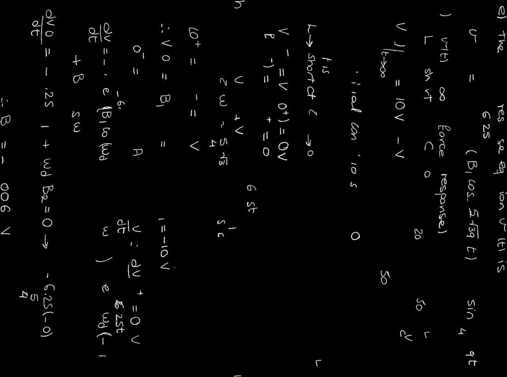
34 ECSE 10, Summer 014 May 9 th, 014 Quiz #1 NAME: ID: Read each question and its parts carefully before starting. Show all your work. Give units with your answers (where appropriate). 1. Consider the circuit diagram shown. At t = 0, the independent current source I s steps up from 0 amperes to 1 ampere and the independent voltage source V s steps down from 5V to 0V. I K is the current passing through R. [10 points] (a) Find the second-order differential equation governing I L (t). [ points] (b) Find the characteristics equation and its roots. [3 points] (c) Is the circuit over-damped, critically damped, or under-damped? Why? [1 point] (d) What is the equation for the natural response? What are the initial conditions? What are the values of the coefficients of the natural response equation? [3 points] (e) Determine I L (t) for t.[1 point] 0A t=0 1A IS C=1µF IL R1=50Ω L=1mH - R=0Ω IK 30 IK - 5V VS 0V t=0 1
35
36 ECSE 10, Summer 014 May 9 th, 014 Quiz #1 NAME: ID: Read each question and its parts carefully before starting. Show all your work. Give units with your answers (where appropriate). 1. Consider the circuit diagram shown. At t = 0, the independent current source I s steps up from 0 amperes to 1 ampere and the independent voltage source V s steps down from 5V to 0V. I K is the current passing through R. [10 points] (a) Find the second-order differential equation governing I L (t). [ points] (b) Find the characteristics equation and its roots. [3 points] (c) Is the circuit over-damped, critically damped, or under-damped? Why? [1 point] (d) What is the equation for the natural response? What are the initial conditions? What are the values of the coefficients of the natural response equation? [3 points] (e) Determine I L (t) for t.[1 point] 0A t=0 1A IS C=1µF IL R1=50Ω L=1mH - R=0Ω IK 30 IK - 5V VS 0V t=0 1
37
To find the step response of an RC circuit
 To find the step response of an RC circuit v( t) v( ) [ v( t) v( )] e tt The time constant = RC The final capacitor voltage v() The initial capacitor voltage v(t ) To find the step response of an RL circuit
Read each question and its parts carefully before starting. Show all your work. Give units with your answers (where appropriate). 1 / 3 F.
. 1 / 3 F.") ECSE 10 NAME: Quiz 18 May 011 ID: Read each question and its parts carefully before starting. Show all your work. Give units with your answers (where appropriate). 1. Consider the circuit diagram below.
ECSE 10 NAME: Quiz 18 May 011 ID: Read each question and its parts carefully before starting. Show all your work. Give units with your answers (where appropriate). 1. Consider the circuit diagram below.
Response of Second-Order Systems
 Unit 3 Response of SecondOrder Systems In this unit, we consider the natural and step responses of simple series and parallel circuits containing inductors, capacitors and resistors. The equations which
Source-Free RC Circuit
 First Order Circuits Source-Free RC Circuit Initial charge on capacitor q = Cv(0) so that voltage at time 0 is v(0). What is v(t)? Prof Carruthers (ECE @ BU) EK307 Notes Summer 2018 150 / 264 First Order
ENGR 2405 Chapter 8. Second Order Circuits
 ENGR 2405 Chapter 8 Second Order Circuits Overview The previous chapter introduced the concept of first order circuits. This chapter will expand on that with second order circuits: those that need a second
Chapter 10: Sinusoids and Phasors
 Chapter 10: Sinusoids and Phasors 1. Motivation 2. Sinusoid Features 3. Phasors 4. Phasor Relationships for Circuit Elements 5. Impedance and Admittance 6. Kirchhoff s Laws in the Frequency Domain 7. Impedance
ECE Circuit Theory. Final Examination. December 5, 2008
 ECE 212 H1F Pg 1 of 12 ECE 212 - Circuit Theory Final Examination December 5, 2008 1. Policy: closed book, calculators allowed. Show all work. 2. Work in the provided space. 3. The exam has 3 problems
Electric Circuit Theory
 Electric Circuit Theory Nam Ki Min nkmin@korea.ac.kr 010-9419-2320 Chapter 8 Natural and Step Responses of RLC Circuits Nam Ki Min nkmin@korea.ac.kr 010-9419-2320 8.1 Introduction to the Natural Response
8. Introduction and Chapter Objectives
 Real Analog - Circuits Chapter 8: Second Order Circuits 8. Introduction and Chapter Objectives Second order systems are, by definition, systems whose input-output relationship is a second order differential
The RLC circuits have a wide range of applications, including oscillators and frequency filters
 9. The RL ircuit The RL circuits have a wide range of applications, including oscillators and frequency filters This chapter considers the responses of RL circuits The result is a second-order differential
Chapter 10: Sinusoidal Steady-State Analysis
 Chapter 10: Sinusoidal Steady-State Analysis 1 Objectives : sinusoidal functions Impedance use phasors to determine the forced response of a circuit subjected to sinusoidal excitation Apply techniques
8 sin 3 V. For the circuit given, determine the voltage v for all time t. Assume that no energy is stored in the circuit before t = 0.
 For the circuit given, determine the voltage v for all time t. Assume that no energy is stored in the circuit before t = 0. Spring 2015, Exam #5, Problem #1 4t Answer: e tut 8 sin 3 V 1 For the circuit
Physics 116A Notes Fall 2004
 Physics 116A Notes Fall 2004 David E. Pellett Draft v.0.9 Notes Copyright 2004 David E. Pellett unless stated otherwise. References: Text for course: Fundamentals of Electrical Engineering, second edition,
EE292: Fundamentals of ECE
 EE292: Fundamentals of ECE Fall 2012 TTh 10:00-11:15 SEB 1242 Lecture 14 121011 http://www.ee.unlv.edu/~b1morris/ee292/ 2 Outline Review Steady-State Analysis RC Circuits RL Circuits 3 DC Steady-State
Circuits with Capacitor and Inductor
 Circuits with Capacitor and Inductor We have discussed so far circuits only with resistors. While analyzing it, we came across with the set of algebraic equations. Hereafter we will analyze circuits with
Sinusoidal Response of RLC Circuits
 Sinusoidal Response of RLC Circuits Series RL circuit Series RC circuit Series RLC circuit Parallel RL circuit Parallel RC circuit R-L Series Circuit R-L Series Circuit R-L Series Circuit Instantaneous
Circuit Analysis-III. Circuit Analysis-II Lecture # 3 Friday 06 th April, 18
 Circuit Analysis-III Sinusoids Example #1 ü Find the amplitude, phase, period and frequency of the sinusoid: v (t ) =12cos(50t +10 ) Signal Conversion ü From sine to cosine and vice versa. ü sin (A ± B)
ECE Spring 2015 Final Exam
 ECE 20100 Spring 2015 Final Exam May 7, 2015 Section (circle below) Jung (1:30) 0001 Qi (12:30) 0002 Peleato (9:30) 0004 Allen (10:30) 0005 Zhu (4:30) 0006 Name PUID Instructions 1. DO NOT START UNTIL
QUESTION BANK SUBJECT: NETWORK ANALYSIS (10ES34)
") QUESTION BANK SUBJECT: NETWORK ANALYSIS (10ES34) NOTE: FOR NUMERICAL PROBLEMS FOR ALL UNITS EXCEPT UNIT 5 REFER THE E-BOOK ENGINEERING CIRCUIT ANALYSIS, 7 th EDITION HAYT AND KIMMERLY. PAGE NUMBERS OF
QUESTION BANK SUBJECT: NETWORK ANALYSIS (10ES34) NOTE: FOR NUMERICAL PROBLEMS FOR ALL UNITS EXCEPT UNIT 5 REFER THE E-BOOK ENGINEERING CIRCUIT ANALYSIS, 7 th EDITION HAYT AND KIMMERLY. PAGE NUMBERS OF
ECE 201 Fall 2009 Final Exam
 ECE 01 Fall 009 Final Exam December 16, 009 Division 0101: Tan (11:30am) Division 001: Clark (7:30 am) Division 0301: Elliott (1:30 pm) Instructions 1. DO NOT START UNTIL TOLD TO DO SO.. Write your Name,
ECE 212H1F Circuit Analysis October 30, :10-19: Reza Iravani 02 Reza Iravani 03 Piero Triverio. (Non-programmable Calculators Allowed)
") Please Print Clearly Last Name: First Name: Student Number: Your Tutorial Section (CIRCLE ONE): 01 Thu. 9-11 RS211 02 Thu. 9-11 GB119 03 Tue. 10-12 SF2202 04 Tue. 10-12 SF3201 05 Tue. 13-15 GB304 06 Tue.
Please Print Clearly Last Name: First Name: Student Number: Your Tutorial Section (CIRCLE ONE): 01 Thu. 9-11 RS211 02 Thu. 9-11 GB119 03 Tue. 10-12 SF2202 04 Tue. 10-12 SF3201 05 Tue. 13-15 GB304 06 Tue.
REACTANCE. By: Enzo Paterno Date: 03/2013
 REACTANCE REACTANCE By: Enzo Paterno Date: 03/2013 5/2007 Enzo Paterno 1 RESISTANCE - R i R (t R A resistor for all practical purposes is unaffected by the frequency of the applied sinusoidal voltage or
MODULE I. Transient Response:
 Transient Response: MODULE I The Transient Response (also known as the Natural Response) is the way the circuit responds to energies stored in storage elements, such as capacitors and inductors. If a capacitor
AC analysis. EE 201 AC analysis 1
 AC analysis Now we turn to circuits with sinusoidal sources. Earlier, we had a brief look at sinusoids, but now we will add in capacitors and inductors, making the story much more interesting. What are
EECE 2510 Circuits and Signals, Biomedical Applications Final Exam Section 3. Name:
 EECE 2510 Circuits and Signals, Biomedical Applications Final Exam Section 3 Instructions: Closed book, closed notes; Computers and cell phones are not allowed Scientific calculators are allowed Complete
Figure Circuit for Question 1. Figure Circuit for Question 2
 Exercises 10.7 Exercises Multiple Choice 1. For the circuit of Figure 10.44 the time constant is A. 0.5 ms 71.43 µs 2, 000 s D. 0.2 ms 4 Ω 2 Ω 12 Ω 1 mh 12u 0 () t V Figure 10.44. Circuit for Question
DEPARTMENT OF ELECTRICAL AND COMPUTER ENGINEERING RUTGERS UNIVERSITY
 DEPARTMENT OF EECTRICA AND COMPUTER ENGINEERING RUTGERS UNIVERSITY 330:222 Principles of Electrical Engineering II Spring 2002 Exam 1 February 19, 2002 SOUTION NAME OF STUDENT: Student ID Number (last
EECS2200 Electric Circuits. RLC Circuit Natural and Step Responses
 5--4 EECS Electric Circuit Chapter 6 R Circuit Natural and Step Repone Objective Determine the repone form of the circuit Natural repone parallel R circuit Natural repone erie R circuit Step repone of
Chapter 10 AC Analysis Using Phasors
 Chapter 10 AC Analysis Using Phasors 10.1 Introduction We would like to use our linear circuit theorems (Nodal analysis, Mesh analysis, Thevenin and Norton equivalent circuits, Superposition, etc.) to
Sinusoidal Steady-State Analysis
 Chapter 4 Sinusoidal Steady-State Analysis In this unit, we consider circuits in which the sources are sinusoidal in nature. The review section of this unit covers most of section 9.1 9.9 of the text.
MODULE-4 RESONANCE CIRCUITS
 Introduction: MODULE-4 RESONANCE CIRCUITS Resonance is a condition in an RLC circuit in which the capacitive and inductive Reactance s are equal in magnitude, there by resulting in purely resistive impedance.
San Jose State University Department of Electrical Engineering. Exam 2 Solution. EE 098-MIT 6.002x Fall 2012
 San Jose State University Department of Electrical Engineering Exam Solution EE 98-MIT 6.x Fall 1 losed Book, losed Notes, and no electronic devices. Instructions: There are six problems. Interpretation
Fall 2011 ME 2305 Network Analysis. Sinusoidal Steady State Analysis of RLC Circuits
 Fall 2011 ME 2305 Network Analysis Chapter 4 Sinusoidal Steady State Analysis of RLC Circuits Engr. Humera Rafique Assistant Professor humera.rafique@szabist.edu.pk Faculty of Engineering (Mechatronics)
Electric Circuits Fall 2015 Solution HW6
 Electric ircuits Fall 05 Solution HW6 RULES: Please try to work on your own. Discussion is permissible, but identical submissions are unacceptable! Please show all intermediate steps: a correct solution
Sinusoidal Steady State Analysis
 Sinusoidal Steady State Analysis 9 Assessment Problems AP 9. [a] V = 70/ 40 V [b] 0 sin(000t +20 ) = 0 cos(000t 70 ).. I = 0/ 70 A [c] I =5/36.87 + 0/ 53.3 =4+j3+6 j8 =0 j5 =.8/ 26.57 A [d] sin(20,000πt
EE292: Fundamentals of ECE
 EE292: Fundamentals of ECE Fall 2012 TTh 10:00-11:15 SEB 1242 Lecture 20 121101 http://www.ee.unlv.edu/~b1morris/ee292/ 2 Outline Chapters 1-3 Circuit Analysis Techniques Chapter 10 Diodes Ideal Model
Electric Circuits Fall 2015 Solution #5
 RULES: Please try to work on your own. Discussion is permissible, but identical submissions are unacceptable! Please show all intermeate steps: a correct solution without an explanation will get zero cret.
Electric Circuits I FINAL EXAMINATION
 EECS:300, Electric Circuits I s6fs_elci7.fm - Electric Circuits I FINAL EXAMINATION Problems Points.. 3. 0 Total 34 Was the exam fair? yes no 5//6 EECS:300, Electric Circuits I s6fs_elci7.fm - Problem
ECE Spring 2017 Final Exam
 ECE 20100 Spring 2017 Final Exam May 2, 2017 Section (circle below) Qi (12:30) 0001 Tan (10:30) 0004 Hosseini (7:30) 0005 Cui (1:30) 0006 Jung (11:30) 0007 Lin (9:30) 0008 Peleato-Inarrea (2:30) 0009 Name
ECE2262 Electric Circuit
 ECE2262 Electric Circuit Chapter 7: FIRST AND SECOND-ORDER RL AND RC CIRCUITS Response to First-Order RL and RC Circuits Response to Second-Order RL and RC Circuits 1 2 7.1. Introduction 3 4 In dc steady
4/27 Friday. I have all the old homework if you need to collect them.
 4/27 Friday Last HW: do not need to turn it. Solution will be posted on the web. I have all the old homework if you need to collect them. Final exam: 7-9pm, Monday, 4/30 at Lambert Fieldhouse F101 Calculator
Prof. Shayla Sawyer CP08 solution
 What does the time constant represent in an exponential function? How do you define a sinusoid? What is impedance? How is a capacitor affected by an input signal that changes over time? How is an inductor
Linear Circuits. Concept Map 9/10/ Resistive Background Circuits. 5 Power. 3 4 Reactive Circuits. Frequency Analysis
 Linear Circuits Dr. Bonnie Ferri Professor School of Electrical and Computer Engineering An introduction to linear electric components and a study of circuits containing such devices. School of Electrical
Name (print): Lab (circle): W8 Th8 Th11 Th2 F8. θ (radians) θ (degrees) cos θ sin θ π/ /2 1/2 π/4 45 2/2 2/2 π/3 60 1/2 3/2 π/
: Lab (circle): W8 Th8 Th11 Th2 F8. θ (radians) θ (degrees) cos θ sin θ π/ /2 1/2 π/4 45 2/2 2/2 π/3 60 1/2 3/2 π/") Name (print): Lab (circle): W8 Th8 Th11 Th2 F8 Trigonometric Identities ( cos(θ) = cos(θ) sin(θ) = sin(θ) sin(θ) = cos θ π ) 2 Cosines and Sines of common angles Euler s Formula θ (radians) θ (degrees)
Name (print): Lab (circle): W8 Th8 Th11 Th2 F8 Trigonometric Identities ( cos(θ) = cos(θ) sin(θ) = sin(θ) sin(θ) = cos θ π ) 2 Cosines and Sines of common angles Euler s Formula θ (radians) θ (degrees)
Chapter 33. Alternating Current Circuits
 Chapter 33 Alternating Current Circuits 1 Capacitor Resistor + Q = C V = I R R I + + Inductance d I Vab = L dt AC power source The AC power source provides an alternative voltage, Notation - Lower case
Lectures 16 & 17 Sinusoidal Signals, Complex Numbers, Phasors, Impedance & AC Circuits. Nov. 7 & 9, 2011
 Lectures 16 & 17 Sinusoidal Signals, Complex Numbers, Phasors, Impedance & AC Circuits Nov. 7 & 9, 2011 Material from Textbook by Alexander & Sadiku and Electrical Engineering: Principles & Applications,
EECE 2150 Circuits and Signals Final Exam Fall 2016 Dec 12
 EECE 2150 Circuits and Signals Final Exam Fall 2016 Dec 12 Instructions: Write your name and section number on all pages Closed book, closed notes; Computers and cell phones are not allowed You can use
Electrical Circuits (2)
") Electrical Circuits (2) Lecture 7 Transient Analysis Dr.Eng. Basem ElHalawany Extra Reference for this Lecture Chapter 16 Schaum's Outline Of Theory And Problems Of Electric Circuits https://archive.org/details/theoryandproblemsofelectriccircuits
Electrical Circuits (2) Lecture 7 Transient Analysis Dr.Eng. Basem ElHalawany Extra Reference for this Lecture Chapter 16 Schaum's Outline Of Theory And Problems Of Electric Circuits https://archive.org/details/theoryandproblemsofelectriccircuits
Basic RL and RC Circuits R-L TRANSIENTS: STORAGE CYCLE. Engineering Collage Electrical Engineering Dep. Dr. Ibrahim Aljubouri
 st Class Basic RL and RC Circuits The RL circuit with D.C (steady state) The inductor is short time at Calculate the inductor current for circuits shown below. I L E R A I L E R R 3 R R 3 I L I L R 3 R
Electric Circuit Theory
 Electric Circuit Theory Nam Ki Min nkmin@korea.ac.kr 010-9419-2320 Chapter 11 Sinusoidal Steady-State Analysis Nam Ki Min nkmin@korea.ac.kr 010-9419-2320 Contents and Objectives 3 Chapter Contents 11.1
1 Phasors and Alternating Currents
 Physics 4 Chapter : Alternating Current 0/5 Phasors and Alternating Currents alternating current: current that varies sinusoidally with time ac source: any device that supplies a sinusoidally varying potential
Sinusoidal steady-state analysis
 Sinusoidal steady-state analysis From our previous efforts with AC circuits, some patterns in the analysis started to appear. 1. In each case, the steady-state voltages or currents created in response
Chapter 4 Transients. Chapter 4 Transients
 Chapter 4 Transients Chapter 4 Transients 1. Solve first-order RC or RL circuits. 2. Understand the concepts of transient response and steady-state response. 1 3. Relate the transient response of first-order
EIT Quick-Review Electrical Prof. Frank Merat
 CIRCUITS 4 The power supplied by the 0 volt source is (a) 2 watts (b) 0 watts (c) 2 watts (d) 6 watts (e) 6 watts 4Ω 2Ω 0V i i 2 2Ω 20V Call the clockwise loop currents i and i 2 as shown in the drawing
Basics of Network Theory (Part-I)
") Basics of Network Theory (PartI). A square waveform as shown in figure is applied across mh ideal inductor. The current through the inductor is a. wave of peak amplitude. V 0 0.5 t (m sec) [Gate 987: Marks]
Basics of Network Theory (PartI). A square waveform as shown in figure is applied across mh ideal inductor. The current through the inductor is a. wave of peak amplitude. V 0 0.5 t (m sec) [Gate 987: Marks]
Sinusoids and Phasors
 CHAPTER 9 Sinusoids and Phasors We now begins the analysis of circuits in which the voltage or current sources are time-varying. In this chapter, we are particularly interested in sinusoidally time-varying
LAPLACE TRANSFORMATION AND APPLICATIONS. Laplace transformation It s a transformation method used for solving differential equation.
 LAPLACE TRANSFORMATION AND APPLICATIONS Laplace transformation It s a transformation method used for solving differential equation. Advantages The solution of differential equation using LT, progresses
Solved Problems. Electric Circuits & Components. 1-1 Write the KVL equation for the circuit shown.
 Solved Problems Electric Circuits & Components 1-1 Write the KVL equation for the circuit shown. 1-2 Write the KCL equation for the principal node shown. 1-2A In the DC circuit given in Fig. 1, find (i)
Sinusoidal Steady-State Analysis
 Sinusoidal Steady-State Analysis Almost all electrical systems, whether signal or power, operate with alternating currents and voltages. We have seen that when any circuit is disturbed (switched on or
Applications of Second-Order Differential Equations
 Applications of Second-Order Differential Equations ymy/013 Building Intuition Even though there are an infinite number of differential equations, they all share common characteristics that allow intuition
Sinusoidal Steady State Analysis (AC Analysis) Part I
 Part I") Sinusoidal Steady State Analysis (AC Analysis) Part I Amin Electronics and Electrical Communications Engineering Department (EECE) Cairo University elc.n102.eng@gmail.com http://scholar.cu.edu.eg/refky/
Sinusoidal Steady State Analysis (AC Analysis) Part I Amin Electronics and Electrical Communications Engineering Department (EECE) Cairo University elc.n102.eng@gmail.com http://scholar.cu.edu.eg/refky/
ELECTRONICS E # 1 FUNDAMENTALS 2/2/2011
 FE Review 1 ELECTRONICS E # 1 FUNDAMENTALS Electric Charge 2 In an electric circuit it there is a conservation of charge. The net electric charge is constant. There are positive and negative charges. Like
Chapter 10: Sinusoidal Steady-State Analysis
 Chapter 0: Sinusoidal Steady-State Analysis Sinusoidal Sources If a circuit is driven by a sinusoidal source, after 5 tie constants, the circuit reaches a steady-state (reeber the RC lab with t = τ). Consequently,
Phasors: Impedance and Circuit Anlysis. Phasors
 Phasors: Impedance and Circuit Anlysis Lecture 6, 0/07/05 OUTLINE Phasor ReCap Capacitor/Inductor Example Arithmetic with Complex Numbers Complex Impedance Circuit Analysis with Complex Impedance Phasor
Schedule. ECEN 301 Discussion #20 Exam 2 Review 1. Lab Due date. Title Chapters HW Due date. Date Day Class No. 10 Nov Mon 20 Exam Review.
 Schedule Date Day lass No. 0 Nov Mon 0 Exam Review Nov Tue Title hapters HW Due date Nov Wed Boolean Algebra 3. 3.3 ab Due date AB 7 Exam EXAM 3 Nov Thu 4 Nov Fri Recitation 5 Nov Sat 6 Nov Sun 7 Nov Mon
First and Second Order Circuits. Claudio Talarico, Gonzaga University Spring 2015
 First and Second Order Circuits Claudio Talarico, Gonzaga University Spring 2015 Capacitors and Inductors intuition: bucket of charge q = Cv i = C dv dt Resist change of voltage DC open circuit Store voltage
SINUSOIDAL STEADY STATE CIRCUIT ANALYSIS
 SINUSOIDAL STEADY STATE CIRCUIT ANALYSIS 1. Introduction A sinusoidal current has the following form: where I m is the amplitude value; ω=2 πf is the angular frequency; φ is the phase shift. i (t )=I m.sin
a + b Time Domain i(τ)dτ.
dτ.") R, C, and L Elements and their v and i relationships We deal with three essential elements in circuit analysis: Resistance R Capacitance C Inductance L Their v and i relationships are summarized below.
R, C, and L Elements and their v and i relationships We deal with three essential elements in circuit analysis: Resistance R Capacitance C Inductance L Their v and i relationships are summarized below.
LINEAR CIRCUIT ANALYSIS (EED) U.E.T. TAXILA 09
 U.E.T. TAXILA 09") LINEAR CIRCUIT ANALYSIS (EED) U.E.T. TAXILA 09 ENGR. M. MANSOOR ASHRAF INTRODUCTION Thus far our analysis has been restricted for the most part to dc circuits: those circuits excited by constant or time-invariant
LINEAR CIRCUIT ANALYSIS (EED) U.E.T. TAXILA 09 ENGR. M. MANSOOR ASHRAF INTRODUCTION Thus far our analysis has been restricted for the most part to dc circuits: those circuits excited by constant or time-invariant
Chapter 10: Sinusoidal Steady-State Analysis
 Chapter 10: Sinusoidal Steady-State Analysis 10.1 10.2 10.3 10.4 10.5 10.6 10.9 Basic Approach Nodal Analysis Mesh Analysis Superposition Theorem Source Transformation Thevenin & Norton Equivalent Circuits
Chapter 9 Objectives
 Chapter 9 Engr8 Circuit Analysis Dr Curtis Nelson Chapter 9 Objectives Understand the concept of a phasor; Be able to transform a circuit with a sinusoidal source into the frequency domain using phasor
EIT Review. Electrical Circuits DC Circuits. Lecturer: Russ Tatro. Presented by Tau Beta Pi The Engineering Honor Society 10/3/2006 1
 EIT Review Electrical Circuits DC Circuits Lecturer: Russ Tatro Presented by Tau Beta Pi The Engineering Honor Society 10/3/2006 1 Session Outline Basic Concepts Basic Laws Methods of Analysis Circuit
Physics for Scientists & Engineers 2
 Electromagnetic Oscillations Physics for Scientists & Engineers Spring Semester 005 Lecture 8! We have been working with circuits that have a constant current a current that increases to a constant current
Problem Set 5 Solutions
 University of California, Berkeley Spring 01 EE /0 Prof. A. Niknejad Problem Set 5 Solutions Please note that these are merely suggested solutions. Many of these problems can be approached in different
EE 40: Introduction to Microelectronic Circuits Spring 2008: Midterm 2
 EE 4: Introduction to Microelectronic Circuits Spring 8: Midterm Venkat Anantharam 3/9/8 Total Time Allotted : min Total Points:. This is a closed book exam. However, you are allowed to bring two pages
Sinusoidal Steady-State Analysis
 Sinusoidal Steady-State Analysis Mauro Forti October 27, 2018 Constitutive Relations in the Frequency Domain Consider a network with independent voltage and current sources at the same angular frequency
EECE251. Circuit Analysis I. Set 4: Capacitors, Inductors, and First-Order Linear Circuits
 EECE25 Circuit Analysis I Set 4: Capacitors, Inductors, and First-Order Linear Circuits Shahriar Mirabbasi Department of Electrical and Computer Engineering University of British Columbia shahriar@ece.ubc.ca
vtusolution.in Initial conditions Necessity and advantages: Initial conditions assist
 Necessity and advantages: Initial conditions assist Initial conditions To evaluate the arbitrary constants of differential equations Knowledge of the behavior of the elements at the time of switching Knowledge
MAE140 Linear Circuits Fall 2016 Final, December 6th Instructions
 MAE40 Linear Circuits Fall 206 Final, December 6th Instructions. This exam is open book. You may use whatever written materials you choose, including your class notes and textbook. You may use a handheld
ECE 212H1F Circuit Analysis October 20, :15-19: Reza Iravani 02 Reza Iravani 03 Ali Nabavi-Niaki. (Non-programmable Calculators Allowed)
") Please Print Clearly Last Name: First Name: Student Number: Your Tutorial Section (CIRCLE ONE): 01 Thu 10:00 12:00 HA403 02 Thu 10:00 12:00 GB412 03 Thu 15:00 17:00 GB412 04 Thu 15:00 17:00 SF2202 05 Fri
Please Print Clearly Last Name: First Name: Student Number: Your Tutorial Section (CIRCLE ONE): 01 Thu 10:00 12:00 HA403 02 Thu 10:00 12:00 GB412 03 Thu 15:00 17:00 GB412 04 Thu 15:00 17:00 SF2202 05 Fri
EECE 2150 Circuits and Signals Final Exam Fall 2016 Dec 9
 EECE 2150 Circuits and Signals Final Exam Fall 2016 Dec 9 Name: Instructions: Write your name and section number on all pages Closed book, closed notes; Computers and cell phones are not allowed You can
AC Circuit Analysis and Measurement Lab Assignment 8
 Electric Circuit Lab Assignments elcirc_lab87.fm - 1 AC Circuit Analysis and Measurement Lab Assignment 8 Introduction When analyzing an electric circuit that contains reactive components, inductors and
Designing Information Devices and Systems II Spring 2016 Anant Sahai and Michel Maharbiz Midterm 2
 EECS 16B Designing Information Devices and Systems II Spring 2016 Anant Sahai and Michel Maharbiz Midterm 2 Exam location: 145 Dwinelle (SIDs ending in 1 and 5) PRINT your student ID: PRINT AND SIGN your
ECE1750, Spring Week 11 Power Electronics
 ECE1750, Spring 2017 Week 11 Power Electronics Control 1 Power Electronic Circuits Control In most power electronic applications we need to control some variable, such as the put voltage of a dc-dc converter,
= 32.0\cis{38.7} = j Ω. Zab = Homework 2 SJTU233. Part A. Part B. Problem 2. Part A. Problem 1
 Homework 2 SJTU233 Problem 1 Find the impedance Zab in the circuit seen in the figure. Suppose that R = 5 Ω. Express Zab in polar form. Enter your answer using polar notation. Express argument in degrees.
Circuits Advanced Topics by Dr. Colton (Fall 2016)
") ircuits Advanced Topics by Dr. olton (Fall 06). Time dependence of general and L problems General and L problems can always be cast into first order ODEs. You can solve these via the particular solution
ircuits Advanced Topics by Dr. olton (Fall 06). Time dependence of general and L problems General and L problems can always be cast into first order ODEs. You can solve these via the particular solution
Homework 2 SJTU233. Part A. Part B. Problem 2. Part A. Problem 1. Find the impedance Zab in the circuit seen in the figure. Suppose that R = 5 Ω.
 Homework 2 SJTU233 Problem 1 Find the impedance Zab in the circuit seen in the figure. Suppose that R = 5 Ω. Express Zab in polar form. Enter your answer using polar notation. Express argument in degrees.
EE292: Fundamentals of ECE
 EE292: Fundamentals of ECE Fall 2012 TTh 10:00-11:15 SEB 1242 Lecture 18 121025 http://www.ee.unlv.edu/~b1morris/ee292/ 2 Outline Review RMS Values Complex Numbers Phasors Complex Impedance Circuit Analysis
Sinusoidal Steady State Analysis (AC Analysis) Part II
 Part II") Sinusoidal Steady State Analysis (AC Analysis) Part II Amin Electronics and Electrical Communications Engineering Department (EECE) Cairo University elc.n102.eng@gmail.com http://scholar.cu.edu.eg/refky/
Sinusoidal Steady State Analysis (AC Analysis) Part II Amin Electronics and Electrical Communications Engineering Department (EECE) Cairo University elc.n102.eng@gmail.com http://scholar.cu.edu.eg/refky/
Handout 10: Inductance. Self-Inductance and inductors
 1 Handout 10: Inductance Self-Inductance and inductors In Fig. 1, electric current is present in an isolate circuit, setting up magnetic field that causes a magnetic flux through the circuit itself. This
Basic Electrical Circuits Analysis ECE 221
 Basic Electrical Circuits Analysis ECE 221 PhD. Khodr Saaifan http://trsys.faculty.jacobs-university.de k.saaifan@jacobs-university.de 1 2 Reference: Electric Circuits, 8th Edition James W. Nilsson, and
09/29/2009 Reading: Hambley Chapter 5 and Appendix A
 EE40 Lec 10 Complex Numbers and Phasors Prof. Nathan Cheung 09/29/2009 Reading: Hambley Chapter 5 and Appendix A Slide 1 OUTLINE Phasors as notation for Sinusoids Arithmetic with Complex Numbers Complex
1. (10 points) Find the general solution to the following second-order differential equation:
 Find the general solution to the following second-order differential equation:") Math 307A, Winter 014 Midterm Solutions Page 1 of 8 1. (10 points) Find the general solution to the following second-order differential equation: 4y 1y + 9y = 9t. To find the general solution to this nonhomogeneous
Math 307A, Winter 014 Midterm Solutions Page 1 of 8 1. (10 points) Find the general solution to the following second-order differential equation: 4y 1y + 9y = 9t. To find the general solution to this nonhomogeneous
Possible
 Department of Electrical Engineering and Computer Science ENGR 21. Introduction to Circuits and Instruments (4) ENGR 21 SPRING 24 FINAL EXAMINATION given 5/4/3 Possible 1. 1 2. 1 3. 1 4. 1 5. 1 6. 1 7.
Electric Circuits I Final Examination
 EECS:300 Electric Circuits I ffs_elci.fm - Electric Circuits I Final Examination Problems Points. 4. 3. Total 38 Was the exam fair? yes no //3 EECS:300 Electric Circuits I ffs_elci.fm - Problem 4 points
S.E. Sem. III [EXTC] Circuits and Transmission Lines
![S.E. Sem. III [EXTC] Circuits and Transmission Lines](/thumbs/76/73906955.jpg "S.E. Sem. III [EXTC] Circuits and Transmission Lines") S.E. Sem. III [EXTC] Circuit and Tranmiion Line Time : Hr.] Prelim Quetion Paper Solution [Mark : 80 Q.(a) Tet whether P() = 5 4 45 60 44 48 i Hurwitz polynomial. (A) P() = 5 4 45 60 44 48 5 45 44 4 60
S.E. Sem. III [EXTC] Circuit and Tranmiion Line Time : Hr.] Prelim Quetion Paper Solution [Mark : 80 Q.(a) Tet whether P() = 5 4 45 60 44 48 i Hurwitz polynomial. (A) P() = 5 4 45 60 44 48 5 45 44 4 60
UC DAVIS. Circuits I Course Outline
 UC DAVIS Circuits I Course Outline ENG 17 Professor Spencer Fall 2010 2041 Kemper Hall Lecture: MWF 4:10-5:00, 1003 Giedt Hall 752-6885 Discussion Section 1: W 1:10-2:00, 55 Roessler CRN: 61417 Discussion
C R. Consider from point of view of energy! Consider the RC and LC series circuits shown:
 ircuits onsider the R and series circuits shown: ++++ ---- R ++++ ---- Suppose that the circuits are formed at t with the capacitor charged to value. There is a qualitative difference in the time development
Chapter 10: Sinusoidal Steady-State Analysis
 Chapter 0: Sinusoidal Steady-State Analysis Sinusoidal Sources If a circuit is driven by a sinusoidal source, after 5 tie constants, the circuit reaches a steady-state (reeber the RC lab with t τ). Consequently,
Physics 4B Chapter 31: Electromagnetic Oscillations and Alternating Current
 Physics 4B Chapter 31: Electromagnetic Oscillations and Alternating Current People of mediocre ability sometimes achieve outstanding success because they don't know when to quit. Most men succeed because