15EE103L ELECTRIC CIRCUITS LAB RECORD
|
|
|
- Joy Powell
- 5 years ago
- Views:
Transcription
1 15EE103L ELECTRIC CIRCUITS LAB RECORD REGISTER NO: NAME OF THE STUDENT: SEMESTER: DEPARTMENT:
2 INDEX SHEET S.No. Date of Experiment Name of the Experiment Date of submission Marks Staff Sign 1 Verification of Kirchhoff s laws 2 Verification of Superposition Verification of Thevenin s and Norton s Theorem Verification of Maximum Power Transfer theorem Verification of Reciprocity theorem Digital simulation of RL transient circuit using PSPICE software. Digital simulation of RC transient circuit using PSPICE software. Digital simulation of Series and Parallel resonance circuit using PSPICE software. Digital simulation of electric circuits(kvland KCL using PSPICE simulation software* Digital simulation of electric circuits(thevenin and Norton theorem) using PSPICE simulation software* Digital simulation of electric circuits(reciprocity and Maximum transfer theorem) using PSPICE simulation software* TOTAL MARKS : AVERAGE :STAFF SIGNATURE:
3 Course Code: 15EE103L Course Title: ELECTRIC CIRCUITS LAB Semester: I/II SESSION PLAN Instructional objectives: 1. Understand and gain knowledge about circuit laws and theorems 2. Gain knowledge about time domain analysis of circuit transients. 3. Understand the concept of resonance in series and parallel circuits 4. Learn how to use the PSPICE software for simulating circuits. Student outcomes (a) an ability to apply knowledge of mathematics, science, and engineering (b) an ability to design and conduct experiments, as well as to analyze and interpret data (e) an ability to identify, formulate, and solve engineering problems (k) an ability to use the techniques, skills, and modern engineering tools necessary for engineering practice. SESSION NO. NAME OF THE EXPERIMENT 1 Verification of Kirchhoff s laws 2 Verification of Superposition Verification of Thevenin s and Norton s Theorem Verification of Maximum Power Transfer theorem Verification of Reciprocity theorem Digital simulation of RL transient circuit using PSPICE software. Digital simulation of RC transient circuit using PSPICE software. Digital simulation of Series and Parallel resonance circuit using PSPICE software. REFERENCES 1. Department Lab Manual 2. R.Jegatheesan, Analyais of Electric Circuits, McGraw Hill Education (India) Edition Sudhakar.A and Shyam Mohan.S.P, Circuits and Networks Analysis and Synthesis, Tata McGraw Hill Publishing Company Ltd., New Delhi, Fourth edition, INSTRUCTIONAL OBJECTIVE Understand and gain knowledge about circuit laws and theorems Gain knowledge about time domain analysis of circuit transients. Understand the concept of resonance in series and parallel circuits 9,10,11 Digital simulation of electric circuits using PSPICE simulation software* 4. Muhammed H Rashid, SPICE for circuits and electronics using PSPICE, PHI, 2nd edition, 2011 Learn how to use the PSPICE software for simulating circuits. *From session1-5 can be simulated using PSPICE software
4 Laboratory Policies : Each lab session lasts two periods and starts promptly. A brief introduction may be given by the instructor at the beginning of the lab. Everybody has to finish on time, so please time yourself carefully. Doing the pre-lab can save you a lot of time. Review the material prior to coming to the lab; consult the textbook(s) if required. Calculate the anticipated theoretical results, and get an idea of the approximate range and scale of the quantities you will be measuring. All laboratory work has to be completed during the designated lab period. Attendance at your regularly scheduled lab period is required. An unexpected absence will result in the loss of credit for your lab. Report: Neatness, organization, and completeness will be rewarded. Points will be deducted for any part that is not clear. Reports Due Dates: The lab reports are due the following week at the beginning of your lab session. Dress code: Please carry your ID card with you always. Wear White coat and shoes for the lab Assessment: Lab Performance - 30% Pre lab - 05% Post Lab - 05% Record - 05% MCQ/Quiz/Viva Voce 05% Model Exam - 10% Final exam - 40% Systems of Tests: Regular laboratory class work over the full semester will carry a weightage of 60%. The remaining 40% weightage will be given by conducting an end semester practical examination for every individual student.
5
6

7 BREAD BOARD CONNECTIONS
8 DEPT. OF ELECTRICAL & ELECTRONICS ENGINEERING SRMIST, Kattankulathur Sub Code & Name: 15EE103L-ELECTRIC CIRCUITS LAB Title of Experiment Name of the candidate Register Number Date of Experiment S.No. Marks Split up Maximum marks Marks obtained 1 Pre Lab questions 05 2 Theoretical calculation 15 3 Conduction of experiment and results 15 4 Post Lab questions 05 Total 40 Staff Signature with date
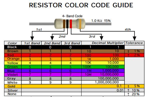
9 PRE LAB 1. Write the colour coding for resistor used in this experiment. 2. What is Breadboard? 3. Define node and branch. 4. Fill in the blanks Prefix Symbol Power of Ten Terra Giga Mega kilo none centi milli T G M k none c m micro µ nano pico n p
10 Experiment No. 1 Date : VERIFICATION OF KIRCHHOFFS LAWS Aim: To verify Kirchhoff s current law and Kirchhoff s voltage law for the given circuit. Apparatus Required: S.No. Apparatus Range Quantity 1 RPS (regulated power supply) (0-30V) 2 2 Resistance 330, 220 1k 1 each 3 Ammeter (0-30mA)MC 3 4 Voltmeter (0-30V)MC 3 5 Bread Board Connecting Wires -- Required Statement: KCL: The algebraic sum of the currents meeting at a node is equal to zero. KVL: In any closed path / mesh, the algebraic sum of all the voltages is zero. Precautions: 1. Voltage control knob should be kept at minimum position. 2. Current control knob of RPS should be kept at maximum position. Procedure for KCL: 1. Give the connections as per the circuit diagram. 2. Set a particular value in RPS. 3. Note down the corresponding ammeter reading 4. Repeat the same for different voltages Procedure for KVL: 1. Give the connections as per the circuit diagram. 2. Set a particular value in RPS. 3. Note all the voltage readings. 4. Repeat the same for different voltages Circuit - KCL
11 Circuit - KVL KCL - Theoretical Values: Sl. Voltage Current I 1 = I 2 + I 3 No. E I 1 I 2 I 3 Volts ma ma ma ma KCL - Practical Values: Sl. Voltage Current I 1 = I 2 + I 3 No. E I 1 I 2 I 3 Volts ma ma ma ma KVL Theoretical Values Sl.No. RPS Voltage KVL E 1 E 2 V 1 V 2 V 3 E 1 = V 1 + V 2 V V V V V V 1 2 3
12 KVL - Practical Values Sl.No. RPS Voltage KVL E 1 E 2 V 1 V 2 V 3 E 1 = V 1 + V 2 V V V V V V Model Calculations:
13 Result: Thus Kirchhoff s voltage law and Kirchhoff s current law were verified both theoretically and practically.
14 POST LAB 1. What is regulated power supply? 2. Explain why an ammeter must be connected in series with a resistor. 3. What modification is done in galvanometer to convert it into an ammeter? 4. How to calculate the error value for the conducted experiment?
15 DEPT. OF ELECTRICAL & ELECTRONICS ENGINEERING SRMIST, Kattankulathur Sub Code & Name: 15EE103L-ELECTRIC CIRCUITS LAB Title of Experiment Name of the candidate Register Number Date of Experiment S.No. Marks Split up Maximum marks Marks obtained 1 Pre Lab questions 05 2 Theoretical calculation 15 3 Conduction of experiment and results 15 4 Post Lab questions 05 Total 40 Staff Signature with date
16 PRELAB 1. a) Read the color codes of the resistors given for this experiment and determine the nominal value and tolerance of each carbon resistor and record them. b) Measure the values of the resistors with the digital multimeter and record them. 2. Define linear network. 3. Explain additivity and homogeneity principles.
17 Experiment No. 2 Date : VERIFICATION OF SUPERPOSITION THEOREM Aim: To verify the superposition theorem for the given circuit. Apparatus Required: Sl.No. Apparatus Range Quantity 1 RPS (regulated power supply) (0-30V) 2 2 Ammeter (0-10mA) 1 3 Resistors 1k, 330, each 4 Bread Board Wires -- Required Statement: Superposition theorem states that in a linear bilateral network containing more than one source, the current flowing through the branch is equal to the algebraic sum of all the currents flowing through that branch when sources are considered one at a time and replacing other sources by their respective internal resistances. Precautions: 1. Voltage control knob of RPS should be kept at minimum position 2. Current control knob of RPS should be kept at maximum position Procedure: 1. Give the connections as per the diagram. 2. Set a particular voltage value using RPS 1 and RPS 2 & note down the ammeter reading 3. Set the same voltage as in circuit 1 using RPS 1 alone and disconnect RPS 2 and short circuit the terminals and note the ammeter reading. 4. Repeat the same procedure with RPS 2 and note down the ammeter reading. 5. Verify superposition theorem. CIRCUIT - 1
18 CIRCUIT - 2 CIRCUIT - 3 TABULAR COLUMN Theoretical Values RPS 1 2 Circuit 1 I= Current (ma) Circuit 2 Circuit 3 I = I = I=I +I = Practical Values RPS 1 2 Circuit 1 I= ma Current (ma) Circuit 2 Circuit 3 I = I = I=I +I = ma
19 Model Calculations:
20 Result: Thus Superposition theorem was been verified both theoretically and practically.
21 POST LAB 1. Using superposition theorem predict the voltage across the load resistor for the experiment conducted. 2. When analyzing circuits, when is it best to use: The Superposition Theorem? 3. What is the internal resistance of the ideal voltage source? 4. Draw the circuit diagram of a practical voltage source with internal resistance.
22 DEPT. OF ELECTRICAL & ELECTRONICS ENGINEERING SRMIST, Kattankulathur Sub Code & Name: 15EE103L-ELECTRIC CIRCUITS LAB Title of Experiment Name of the candidate Register Number Date of Experiment S.No. Marks Split up Maximum marks Marks obtained 1 Pre Lab questions 05 2 Theoretical calculation 15 3 Conduction of experiment and results 15 4 Post Lab questions 05 Total 40 Staff Signature with date
23 PRELAB 1. How to model a practical current source using an ideal current source with an internal resistance Rs. 2. Define active and bilateral network. 3. What do you mean by looking back resistance? 4. What is the use of Thevenin s theorem?
24 Experiment No. 3a Date : VERIFICATION OF THEVENIN S THEOREM Aim: To verify Thevenin s theorem and to calculate the load current for the given circuit. Apparatus Required: Sl.No. Apparatus Range Quantity 1 RPS (regulated power supply) (0-30V) 2 2 Ammeter (0-10mA) 1 3 Resistors 1K, 330 3,1 4 Bread Board -- Required 5 DRB -- 1 Statement: Any linear bilateral, active two terminal network can be replaced by a equivalent voltage source (V TH ). Thevenin s voltage or V OC in series with looking back resistance R TH. Precautions: 1. Voltage control knob of RPS should be kept at minimum position. 2. Current control knob of RPS should be kept at maximum position Procedure: 1. Connections are given as per the circuit diagram. 2. Set a particular value of voltage using RPS and note down the corresponding ammeter readings. To find V TH 3. Remove the load resistance and measure the open circuit voltage using multimeter (V TH ). To find R TH 4. To find the Thevenin s resistance, remove the RPS and short circuit it and find the R TH using multimeter. 5. Give the connections for equivalent circuit and set V TH and R TH and note the corresponding ammeter reading. 6. Verify Thevenins theorem. Theoretical and Practical Values E(V) V TH (V) R TH ( ) I L (ma) Circuit - I Equivalent Circuit Theoretical Practical
25 Circuit - 1 : To find load current To find V TH To find R TH Thevenin s Equivalent circuit:
26 Model Calculations: Result: Thus Thevenin s theorem was verified both practically and theoretically.
27 Experiment No. 3b Date : VERIFICATION OF NORTON S THEOREM Aim: To verify Norton s theorem for the given circuit and to determine the load current for the given circuit. Apparatus Required: Sl.No. Apparatus Range Quantity 1 Ammeter (0-10mA) MC (0-30mA) MC Resistors 330, 1K 3,1 3 RPS (0-30V) 2 4 Bread Board Wires -- Required Statement: Any linear, bilateral, active two terminal network can be replaced by an equivalent current source (I N ) in parallel with Norton s resistance (R N ) Precautions: 1. Voltage control knob of RPS should be kept at minimum position. 2. Current control knob of RPS should be kept at maximum position. Procedure: 1. Connections are given as per circuit diagram. 2. Set a particular value in RPS and note down the ammeter readings in the original circuit. To Find I N : 3. Remove the load resistance and short circuit the terminals. 4. For the same RPS voltage note down the ammeter readings. To Find R N : 5. Remove RPS and short circuit the terminal and remove the load and note down the resistance across the two terminals. Equivalent Circuit: 6. Set I N and R N and note down the ammeter readings. 7. Verify Norton s theorem.
28 Circuit - I To find load current: To find I N To find R N Norton s equivalent circuit
29 Theoretical and Practical Values E (volts) Theoretical Values Practical Values I N (ma) R N ( ) Circuit - I I L (ma) Equivalent Circuit Model Calculations: Result: Thus Norton s theorem was verified both practically and theoretically.
30 POST LAB 1. Calculate and compare the total power supplied by source in the original circuit and Thevenin s circuit from experimental data. 2. Obtain the Norton s equivalent circuit from Thevenin s equivalent circuit. 3. Discuss the relationship of terminal voltage with increase in load resistance. 4. Write Applications of Thevenin s and Norton s Theorem.
31 DEPT. OF ELECTRICAL & ELECTRONICS ENGINEERING SRMIST, Kattankulathur Sub Code & Name: 15EE103L-ELECTRIC CIRCUITS LAB Title of Experiment Name of the candidate Register Number Date of Experiment S.No. Marks Split up Maximum marks Marks obtained 1 Pre Lab questions 05 2 Theoretical calculation 15 3 Conduction of experiment and results 15 4 Post Lab questions 05 Total 40 Staff Signature with date
32 PRELAB 1. Write the condition for maximum power transfer in AC circuit. 2. Write the applications of maximum power transfer theorem. 3. What is DRB? Why it is used? 4. What is load matching?
33 Experiment No. 4 Date : VERIFICATION OF MAXIMUM POWER TRANSFER THEOREM Aim: To verify maximum power transfer theorem for the given DC circuit Apparatus Required: Sl.No. Apparatus Range Quantity 1 RPS (0-30V) 1 2 Voltmeter (0-10V) MC 1 3 Ammeter (0-10mA) MC 1 4 Resistor 1k 4 5 DRB Multimeter Bread Board & wires -- Required Statement: In a linear, bilateral circuit the maximum power will be transferred to the load when load resistance is equal to source resistance. Precautions: 1. Voltage control knob of RPS should be kept at minimum position. 2. Current control knob of RPS should be kept at maximum position. Procedure: Circuit I 1. Connections are given as per the diagram and set a particular voltage in RPS. 2. Vary R L and note down the corresponding ammeter and voltmeter reading. 3. Repeat the procedure for different values of R L & Tabulate it. 4. Calculate the power for each value of R L. To find V TH : 5. Remove the load, and determine the open circuit voltage using multimeter (V TH ) To find R TH : 6. Remove the load and short circuit the voltage source (RPS). 7. Find the looking back resistance (R TH ) using multimeter. Equivalent Circuit: 8. Set V TH using RPS and R TH using DRB and note down the ammeter reading. 9. Calculate the power delivered to the load (R L = R TH ) 10. Verify maximum transfer theorem.
34 Circuit - 1 To find V TH To find R TH Thevenin s Equivalent Circuit
35 Power V S R L Circuit I Sl.No. R L ( ) I (ma) V(V) P=VI (watts) To find Thevenin s equivalent circuit V TH (V) R TH ( ) I L (ma) P (milli watts) Theoretical Value Practical Values Model Calculations:
36 Result: Thus maximum power theorem was verified both practically and theoretically.
37 POSTLAB 1. Discuss the reasons for any discrepancies between the theoretical and experimental values. 2. Plot the theoretical and experimental values of P L versus R L (on the same graph). 3. Compare the two graphs. 4. Why the voltmeter must be connected in parallel?
38 DEPT. OF ELECTRICAL & ELECTRONICS ENGINEERING SRMIST, Kattankulathur Sub Code & Name: 15EE103L-ELECTRIC CIRCUITS LAB Title of Experiment Name of the candidate Register Number Date of Experiment S.No. Marks Split up Maximum marks Marks obtained 1 Pre Lab questions 05 2 Theoretical calculation 15 3 Conduction of experiment and results 15 4 Post Lab questions 05 Total 40 Staff Signature with date
39 PRELAB 1. Transform a physical voltage source into its equivalent current source. 2. Why reciprocity theorem is not applicable to unilateral circuits? 3. Why it is called as reciprocity theorem?
40 Experiment No. 5 Date : VERIFICATION OF RECIPROCITY THEOREM Aim: To verify the reciprocity theorem for the given circuit. Apparatus Required: Sl.No. Apparatus Range Quantity 1 RPS (0-30V) 1 2 Ammeter (0-30mA) MC 1 3 Resistor 1k, 470,330 1 each 4 DRB Bread Board & wires -- Required Statement: In any linear, bilateral, single source network, the ratio of response to the excitation is same even though the positions of excitation and response are interchanged. Precautions: 1. Voltage control knob of RPS should be kept at minimum position. 2. Current control knob of RPS should be kept at maximum position. Procedure: 3. Connections are given as per the diagram and set a particular voltage in RPS in circuit-i. 4. Note down the corresponding ammeter reading. 5. Inter change the position of voltage source and ammeter as shown in the circuit. 6. Set the same voltage in RPS as in circuit-i now in circuit-ii and note down the ammeter reading & tabulate it. 7. Verify reciprocity theorem. Circuit-I
41 Circuit-II Tabular Column: RPS(E) Volts Circuit I I= Theoretical value Current (ma) Practical value Current (ma) Circuit II I= Model Calculations:
42 Result: Thus reciprocity theorem was verified both practically and theoretically
43 POSTLAB 1. What are the limitations of reciprocity theorem? 2. What do you mean by excitation and response? 3. What is transfer resistance or impedance?
44 DEPT. OF ELECTRICAL & ELECTRONICS ENGINEERING SRMIST, Kattankulathur Sub Code & Name: 15EE103L-ELECTRIC CIRCUITS LAB Title of Experiment Name of the candidate Register Number Date of Experiment S.No. Marks Split up Maximum marks Marks obtained 1 Pre Lab questions 05 2 Circuit simulation 15 3 Results 15 4 Post Lab questions 05 Total 40 Staff Signature with date
45 PRELAB 1. Define transients. 2. Derive the transient current expression for the given RL circuit. 3. What is the characteristic time constant for the following circuit given in this experiment? Take R = 4.7 kω, and L = 1 mh. 4. What is PSPICE?
46 Experiment No. 6 Date : DIGITAL SIMULATION OF RL TRANSIENT CIRCUIT USING PSPICE Aim : To determine the transient current and voltage across element through RL series circuits using PSPICE. RL TRANSIENT Given Circuit: Output: i) Current i(t) vs time(t)

47 ii) Voltage V R Vs time(t) Result: The transient currents and voltage for the given RL circuit was determined by simulation using PSPICE.
48 POSTLAB 1. Write the procedure for simulating the given circuit using PSPICE. 2. Write the PSPICE coding for the circuit given in this experiment. 3. Draw the voltage across inductor and current through the inductor waveform.
49 DEPT. OF ELECTRICAL & ELECTRONICS ENGINEERING SRMIST, Kattankulathur Sub Code & Name: 15EE103L-ELECTRIC CIRCUITS LAB Title of Experiment Name of the candidate Register Number Date of Experiment S.No. Marks Split up Maximum marks Marks obtained 1 Pre Lab questions 05 2 Circuit simulation 15 3 Results 15 4 Post Lab questions 05 Total 40 Staff Signature with date
50 PRELAB 1. Define time constant for RC circuit. 2. What do you mean by forced and free response? 3. What is the initial condition for voltage across and current through capacitor in the series RC transient circuit? 4. Derive the transient current expression for the given circuit.
51 Experiment No. 7 Date : DIGITAL SIMULATION OF RC TRANSIENT CIRCUIT USING PSPICE Aim: To determine the transient current and voltage across element for the given RC series circuit using PSPICE. RC TRANSIENT Given Circuit: Output: i) Current i(t) vs time(t)
52 ii) Voltage V C Vs time(t) Result: The transient currents and voltage through the given RC circuit were determined by simulation using PSPICE.
53 POSTLAB 1. Draw the current and voltage waveforms of resistor in the given circuit. 2. If the switch remains closed for a long time, what will the value of current in the given circuit? 3. How much voltage is on the capacitor in the circuit given in this experiment at t = 15 s?
54 DEPT. OF ELECTRICAL & ELECTRONICS ENGINEERING SRMIST, Kattankulathur Sub Code & Name: 15EE103L-ELECTRIC CIRCUITS LAB Title of Experiment Name of the candidate Register Number Date of Experiment S.No. Marks Split up Maximum marks Marks obtained 1 Pre Lab questions 05 2 Circuit simulation 15 3 Results 15 4 Post Lab questions 05 Total 40 Staff Signature with date
55 PRELAB 1. Derive the expression for resonance frequency in series RLC circuit. 2. When RLC series circuit is said to be at resonance? 3. Write the properties of parallel resonance circuit. 4. Define bandwidth.
56 Experiment No. 8 Date : DIGITAL SIMULATION OF SERIES AND PARALLEL RESONANCE CIRCUIT USING PSPICE SOFTWARE. Aim: To simulate RLC series and parallel resonance circuit using PSPICE. Given Circuit: Series resonance circuit: Parallel resonance circuit:
57 Voltage and Current curves: Result: Thus the series and parallel resonance circuit was simulated using PSPICE software
58 DEPT. OF ELECTRICAL & ELECTRONICS ENGINEERING SRMIST, Kattankulathur Sub Code & Name: 15EE103L-ELECTRIC CIRCUITS LAB Title of Experiment Name of the candidate Register Number Date of Experiment S.No. Marks Split up Maximum marks Marks obtained 1 Pre Lab questions 05 2 Circuit simulation 15 3 Results 15 4 Post Lab questions 05 Total 40 Staff Signature with date
59 Experiment No. 9 Date : DIGITAL SIMULATION OF ELECTRIC CIRCUITS USING PSPICE SIMULATION Aim: To Simulate the given electric circuit using in PSPICE and to determine the voltage across and current through the resistors. KVL and KCL circuit: Superposition theorem: With both the sources: With one source alone:
60 With the other source alone: Thevenin s theorem: To find Vth: PSPICE PROGRAMMING: EXAMPLE:
61 Text editor: * DC circuit VS V R R K R R END The meaning of the lines is 1. * Text File we need a first line for the file, it can be a title or comment line but should not be part of the circuit net list. 2. Vs Vs means a voltage source, 1 0 are the nodes it is connected between, and the last 12 is the voltage value. All nodes must be numbered, with 0 = ground node. 3. R R1 means a resistor, 1, 2 are the nodes it is connected between, and 10 is its value. Other commands: DC Vin DC means a DC sweep, Vin means Vin is the sweep variable, 0 12 is the range of the sweep and 0.1 is the sweep increment. PROBE calls PROBE to plot the simulation. A blank plot comes up and the TRACE/ADD menu can be used to select a variable for display To run the file, right click the mouse on the cir file icon to obtain the OPEN WITH/PSPICE SIMULATOR menu Result: Thus the given electric circuits were simulated using PSPICE software.
Experiment 2: Analysis and Measurement of Resistive Circuit Parameters
 Experiment 2: Analysis and Measurement of Resistive Circuit Parameters Report Due In-class on Wed., Mar. 28, 2018 Pre-lab must be completed prior to lab. 1.0 PURPOSE To (i) verify Kirchhoff's laws experimentally;
POLYTECHNIC UNIVERSITY Electrical Engineering Department. EE SOPHOMORE LABORATORY Experiment 2 DC circuits and network theorems
 POLYTECHNIC UNIVERSITY Electrical Engineering Department EE SOPHOMORE LABORATORY Experiment 2 DC circuits and network theorems Modified for Physics 18, Brooklyn College I. Overview of Experiment In this
NETWORK ANALYSIS ( ) 2012 pattern
 2012 pattern") PRACTICAL WORK BOOK For Academic Session 0 NETWORK ANALYSIS ( 0347 ) 0 pattern For S.E. (Electrical Engineering) Department of Electrical Engineering (University of Pune) SHREE RAMCHANDRA COLLEGE OF ENGG.
PRACTICAL WORK BOOK For Academic Session 0 NETWORK ANALYSIS ( 0347 ) 0 pattern For S.E. (Electrical Engineering) Department of Electrical Engineering (University of Pune) SHREE RAMCHANDRA COLLEGE OF ENGG.
Marwadi University Draft Syllabus for Bachelor of Technology Electronics and Communication. Subject Code: 03EC0302
 Subject Code: 03EC0302 Subject Name: Circuits and Networks B. Tech. Year II (Semester III) Objective: After completion of this course, student will be able to: 1. To introduce electric circuits and its
Prerequisites: Successful completion of PHYS 2222 General Physics (Calculus) with a grade of C or better.
 with a grade of C or better.") Prepared by: P. Blake Reviewed by: M. Mayfield Date prepared: March 13, 2017 C&GE approved: April 17, 2017 Board approved: May 10, 2017 Semester effective: Spring 2018 Engineering (ENGR) 2000 Circuit Analysis
Prepared by: P. Blake Reviewed by: M. Mayfield Date prepared: March 13, 2017 C&GE approved: April 17, 2017 Board approved: May 10, 2017 Semester effective: Spring 2018 Engineering (ENGR) 2000 Circuit Analysis
UNIT 4 DC EQUIVALENT CIRCUIT AND NETWORK THEOREMS
 UNIT 4 DC EQUIVALENT CIRCUIT AND NETWORK THEOREMS 1.0 Kirchoff s Law Kirchoff s Current Law (KCL) states at any junction in an electric circuit the total current flowing towards that junction is equal
Chapter 2. Engr228 Circuit Analysis. Dr Curtis Nelson
 Chapter 2 Engr228 Circuit Analysis Dr Curtis Nelson Chapter 2 Objectives Understand symbols and behavior of the following circuit elements: Independent voltage and current sources; Dependent voltage and
DEPARTMENT OF COMPUTER ENGINEERING UNIVERSITY OF LAHORE
 DEPARTMENT OF COMPUTER ENGINEERING UNIVERSITY OF LAHORE NAME. Section 1 2 3 UNIVERSITY OF LAHORE Department of Computer engineering Linear Circuit Analysis Laboratory Manual 2 Compiled by Engr. Ahmad Bilal
DC Circuits Analysis
 Western Technical College 10660117 DC Circuits Analysis Course Outcome Summary Course Information Description Career Cluster Instructional Level Total Credits 2.00 Total Hours 54.00 This course provides
Chapter 5. Department of Mechanical Engineering
 Source Transformation By KVL: V s =ir s + v By KCL: i s =i + v/r p is=v s /R s R s =R p V s /R s =i + v/r s i s =i + v/r p Two circuits have the same terminal voltage and current Source Transformation
Voltage Dividers, Nodal, and Mesh Analysis
 Engr228 Lab #2 Voltage Dividers, Nodal, and Mesh Analysis Name Partner(s) Grade /10 Introduction This lab exercise is designed to further your understanding of the use of the lab equipment and to verify
QUESTION BANK SUBJECT: NETWORK ANALYSIS (10ES34)
") QUESTION BANK SUBJECT: NETWORK ANALYSIS (10ES34) NOTE: FOR NUMERICAL PROBLEMS FOR ALL UNITS EXCEPT UNIT 5 REFER THE E-BOOK ENGINEERING CIRCUIT ANALYSIS, 7 th EDITION HAYT AND KIMMERLY. PAGE NUMBERS OF
QUESTION BANK SUBJECT: NETWORK ANALYSIS (10ES34) NOTE: FOR NUMERICAL PROBLEMS FOR ALL UNITS EXCEPT UNIT 5 REFER THE E-BOOK ENGINEERING CIRCUIT ANALYSIS, 7 th EDITION HAYT AND KIMMERLY. PAGE NUMBERS OF
Prepare for this experiment!
 Notes on Experiment #8 Theorems of Linear Networks Prepare for this experiment! If you prepare, you can finish in 90 minutes. If you do not prepare, you will not finish even half of this experiment. So,
ECE 220 Laboratory 4 Volt Meter, Comparators, and Timer
 ECE 220 Laboratory 4 Volt Meter, Comparators, and Timer Michael W. Marcellin Please follow all rules, procedures and report requirements as described at the beginning of the document entitled ECE 220 Laboratory
Basic Electrical Circuits Analysis ECE 221
 Basic Electrical Circuits Analysis ECE 221 PhD. Khodr Saaifan http://trsys.faculty.jacobs-university.de k.saaifan@jacobs-university.de 1 2 Reference: Electric Circuits, 8th Edition James W. Nilsson, and
AC Circuit Analysis and Measurement Lab Assignment 8
 Electric Circuit Lab Assignments elcirc_lab87.fm - 1 AC Circuit Analysis and Measurement Lab Assignment 8 Introduction When analyzing an electric circuit that contains reactive components, inductors and
D C Circuit Analysis and Network Theorems:
 UNIT-1 D C Circuit Analysis and Network Theorems: Circuit Concepts: Concepts of network, Active and passive elements, voltage and current sources, source transformation, unilateral and bilateral elements,
Thevenin Norton Equivalencies - GATE Study Material in PDF
 Thevenin Norton Equivalencies - GATE Study Material in PDF In these GATE 2018 Notes, we explain the Thevenin Norton Equivalencies. Thevenin s and Norton s Theorems are two equally valid methods of reducing
Kirchhoff's Laws and Maximum Power Transfer
 German Jordanian University (GJU) Electrical Circuits Laboratory Section Experiment Kirchhoff's Laws and Maximum Power Transfer Post lab Report Mahmood Hisham Shubbak / / 8 Objectives: To learn KVL and
EDEXCEL NATIONALS UNIT 5 - ELECTRICAL AND ELECTRONIC PRINCIPLES. ASSIGNMENT No.2 - CAPACITOR NETWORK
 EDEXCEL NATIONALS UNIT 5 - ELECTRICAL AND ELECTRONIC PRINCIPLES ASSIGNMENT No.2 - CAPACITOR NETWORK NAME: I agree to the assessment as contained in this assignment. I confirm that the work submitted is
ELECTRICAL MEASUREMENTS LAB MANUAL
 ELECTRICAL MEASUREMENTS LAB MANUAL Prepared by B.SAIDAMMA R13 Regulation Any 10 of the following experiments are to be conducted 1. Calibration and Testing of single phase energy Meter 2. Calibration of
Sirindhorn International Institute of Technology Thammasat University at Rangsit
 Sirindhorn International Institute of Technology Thammasat University at Rangsit School of Information, Computer and Communication Technology COURSE : ECS 304 Basic Electrical Engineering Lab INSTRUCTOR
Basic. Theory. ircuit. Charles A. Desoer. Ernest S. Kuh. and. McGraw-Hill Book Company
 Basic C m ш ircuit Theory Charles A. Desoer and Ernest S. Kuh Department of Electrical Engineering and Computer Sciences University of California, Berkeley McGraw-Hill Book Company New York St. Louis San
STATEWIDE CAREER/TECHNICAL EDUCATION COURSE ARTICULATION REVIEW MINUTES
 STATEWIDE CAREER/TECHNICAL EDUCATION COURSE ARTICULATION REVIEW MINUTES Articulation Agreement Identifier: _ELT 107/ELT 108 (2011-1) Plan-of-Instruction version number (e.g.; INT 100 (2007-1)). Identifier
UNIVERSITY OF TECHNOLOGY, JAMAICA Faculty of Engineering and Computing School of Engineering
 UNIVERSITY OF TECHNOLOGY, JAMAICA Faculty of Engineering and Computing School of Engineering SYLLABUS OUTLINE FACULTY: SCHOOL/DEPT: COURSE OF STUDY: Engineering and Computing Engineering Diploma in Electrical
UNIVERSITY F P RTLAND Sch l f Engineering
 UNIVERSITY F P RTLAND Sch l f Engineering EE271-Electrical Circuits Laboratory Spring 2004 Dr. Aziz S. Inan & Dr. Joseph P. Hoffbeck Lab Experiment #4: Electrical Circuit Theorems - p. 1 of 5 - Electrical
Updated: Page 1 of 6
 MASTER SYLLABUS 2018-2019 A. Academic Division: Business, Industry, and Technology B. Discipline: Electronic Engineering Technology C. Course Number and Title: ELET1510 DC Electricity D. Course Coordinator:
RC, RL, and LCR Circuits
 RC, RL, and LCR Circuits EK307 Lab Note: This is a two week lab. Most students complete part A in week one and part B in week two. Introduction: Inductors and capacitors are energy storage devices. They
Science Olympiad Circuit Lab
 Science Olympiad Circuit Lab Key Concepts Circuit Lab Overview Circuit Elements & Tools Basic Relationships (I, V, R, P) Resistor Network Configurations (Series & Parallel) Kirchhoff s Laws Examples Glossary
Basic RL and RC Circuits R-L TRANSIENTS: STORAGE CYCLE. Engineering Collage Electrical Engineering Dep. Dr. Ibrahim Aljubouri
 st Class Basic RL and RC Circuits The RL circuit with D.C (steady state) The inductor is short time at Calculate the inductor current for circuits shown below. I L E R A I L E R R 3 R R 3 I L I L R 3 R
FACULTY OF ENGINEERING LAB SHEET. IM1: Wheatstone and Maxwell Wien Bridges
 FCULTY OF ENGINEEING LB SHEET EEL96 Instrumentation & Measurement Techniques TIMESTE 08-09 IM: Wheatstone and Maxwell Wien Bridges *Note: Please calculate the computed values for Tables. and. before the
ELEC 250: LINEAR CIRCUITS I COURSE OVERHEADS. These overheads are adapted from the Elec 250 Course Pack developed by Dr. Fayez Guibaly.
 Elec 250: Linear Circuits I 5/4/08 ELEC 250: LINEAR CIRCUITS I COURSE OVERHEADS These overheads are adapted from the Elec 250 Course Pack developed by Dr. Fayez Guibaly. S.W. Neville Elec 250: Linear Circuits
Chapter 10 AC Analysis Using Phasors
 Chapter 10 AC Analysis Using Phasors 10.1 Introduction We would like to use our linear circuit theorems (Nodal analysis, Mesh analysis, Thevenin and Norton equivalent circuits, Superposition, etc.) to
MUFFAKHAM JAH COLLEGE OF ENGINEERING & TECHNOLOGY. Banjara Hills Road No 3, Hyderabad 34. DEPARTMENT OF ELECTRICAL ENGINEERING
 MUFFAKHAM JAH COLLEGE OF ENGINEERING & TECHNOLOGY Banjara Hills Road No 3, Hyderabad 34 www.mjcollege.ac.in DEPARTMENT OF ELECTRICAL ENGINEERING LABORATORY MANUAL CIRCUITS AND MEASUREMENTS LAB For B.E.
NZQA registered unit standard version 2 Page 1 of 6
 Page 1 of 6 Title Demonstrate and apply knowledge of capacitance, inductance, power factor, and power factor correction Level 3 Credits 7 Purpose This unit standard covers an introduction to alternating
LABORATORY 4 ELECTRIC CIRCUITS I. Objectives
 LABORATORY 4 ELECTRIC CIRCUITS I Objectives to be able to discuss potential difference and current in a circuit in terms of electric field, work per unit charge and motion of charges to understand that
 Network Topology-2 & Dual and Duality Choice of independent branch currents and voltages: The solution of a network involves solving of all branch currents and voltages. We know that the branch current
ELECTRIC CIRCUITS I (ELCT 301)
") German University in Cairo Faculty of Information Engineering and Technology (IET) ELECTRIC CIRCUITS I (ELCT 301) LECTURE 1: BASIC CONCEPTS COURSE INSTRUCTOR Instructor: Prof. Dr. Eng. Yasser G. Hegazy
German University in Cairo Faculty of Information Engineering and Technology (IET) ELECTRIC CIRCUITS I (ELCT 301) LECTURE 1: BASIC CONCEPTS COURSE INSTRUCTOR Instructor: Prof. Dr. Eng. Yasser G. Hegazy
OAKTON COMMUNITY COLLEGE COURSE SYLLABUS. I. Course Course Course Prefix Number Name Credit: Lecture Lab. PHY 132 College Physics II 4 3 2
 OAKTON COMMUNITY COLLEGE COURSE SYLLABUS I. Course Course Course Prefix Number Name Credit: Lecture Lab PHY 132 College Physics II 4 3 2 II. Prerequisites: PHY 131 III. Course (catalog) Description: Course
ECE2262 Electric Circuits
 ECE2262 Electric Circuits Equivalence Chapter 5: Circuit Theorems Linearity Superposition Thevenin s and Norton s Theorems Maximum Power Transfer Analysis of Circuits Using Circuit Theorems 1 5. 1 Equivalence
Electricity and Light Pre Lab Questions
 Electricity and Light Pre Lab Questions The pre lab questions can be answered by reading the theory and procedure for the related lab. You are strongly encouraged to answers these questions on your own.
Laboratory #1: Inductive and Capacitive Transients Electrical and Computer Engineering EE University of Saskatchewan
 Authors: Denard Lynch Date: July, 16, 2012 Corrections: Sep 16, 2012 D. Lynch, M. R. Avendi Revised: Sep 22, 2012 D. Lynch Revised: Sep 9, 2013 Description: This laboratory exercise explores resistance
Chapter 10: Sinusoidal Steady-State Analysis
 Chapter 10: Sinusoidal Steady-State Analysis 10.1 10.2 10.3 10.4 10.5 10.6 10.9 Basic Approach Nodal Analysis Mesh Analysis Superposition Theorem Source Transformation Thevenin & Norton Equivalent Circuits
2. Basic Components and Electrical Circuits
 1 2. Basic Components and Electrical Circuits 2.1 Units and Scales The International System of Units (SI) defines 6 principal units from which the units of all other physical quantities can be derived
Chapter 10 Sinusoidal Steady State Analysis Chapter Objectives:
 Chapter 10 Sinusoidal Steady State Analysis Chapter Objectives: Apply previously learn circuit techniques to sinusoidal steady-state analysis. Learn how to apply nodal and mesh analysis in the frequency
Experiment 4: Resistances in Circuits
 Name: Partners: Date: Experiment 4: Resistances in Circuits EQUIPMENT NEEDED: Circuits Experiment Board Multimeter Resistors Purpose The purpose of this lab is to begin experimenting with the variables
EXPERIMENT 12 OHM S LAW
 EXPERIMENT 12 OHM S LAW INTRODUCTION: We will study electricity as a flow of electric charge, sometimes making analogies to the flow of water through a pipe. In order for electric charge to flow a complete
EXPERIMENT 07 TO STUDY DC RC CIRCUIT AND TRANSIENT PHENOMENA
 EXPERIMENT 07 TO STUDY DC RC CIRCUIT AND TRANSIENT PHENOMENA DISCUSSION The capacitor is a element which stores electric energy by charging the charge on it. Bear in mind that the charge on a capacitor
Lab 4 CAPACITORS & RC CIRCUITS
 67 Name Date Partners Lab 4 CAPACITORS & RC CIRCUITS OBJECTIVES OVERVIEW To define capacitance and to learn to measure it with a digital multimeter. To explore how the capacitance of conducting parallel
PHYSICS 171. Experiment 3. Kirchhoff's Laws. Three resistors (Nominally: 1 Kilohm, 2 Kilohm, 3 Kilohm).
.") PHYSICS 171 Experiment 3 Kirchhoff's Laws Equipment: Supplies: Digital Multimeter, Power Supply (0-20 V.). Three resistors (Nominally: 1 Kilohm, 2 Kilohm, 3 Kilohm). A. Kirchhoff's Loop Law Suppose that
PHYSICS 171 Experiment 3 Kirchhoff's Laws Equipment: Supplies: Digital Multimeter, Power Supply (0-20 V.). Three resistors (Nominally: 1 Kilohm, 2 Kilohm, 3 Kilohm). A. Kirchhoff's Loop Law Suppose that
Some Important Electrical Units
 Some Important Electrical Units Quantity Unit Symbol Current Charge Voltage Resistance Power Ampere Coulomb Volt Ohm Watt A C V W W These derived units are based on fundamental units from the meterkilogram-second
.. Use of non-programmable scientific calculator is permitted.
 This question paper contains 8+3 printed pages] Roll No. S. No. of Question Paper 7981 Cnique Paper Code 1\;ame of the Paper ~ame of the Course Semester Duration : 3 Hours 2511102 Circuit Analysis [DC-1.1]
Chapter 4 Circuit Theorems
 Chapter 4 Circuit Theorems 1. Linearity and Proportionality. Source Transformation 3. Superposition Theorem 4. Thevenin s Theorem and Norton s Theorem 5. Maximum Power Transfer Theorem Mazita Sem 1 111
Lab 10: DC RC circuits
 Name: Lab 10: DC RC circuits Group Members: Date: TA s Name: Objectives: 1. To understand current and voltage characteristics of a DC RC circuit 2. To understand the effect of the RC time constant Apparatus:
THERE MUST BE 50 WAYS TO FIND YOUR VALUES: AN EXPLORATION OF CIRCUIT ANALYSIS TECHNIQUES FROM OHM S LAW TO EQUIVALENT CIRCUITS
 THERE MUST BE 50 WAYS TO FIND YOUR VALUES: AN EXPLORATION OF CIRCUIT ANALYSIS TECHNIQUES FROM OHM S LAW TO EQUIVALENT CIRCUITS Kristine McCarthy Josh Pratti Alexis Rodriguez-Carlson November 20, 2006 Table
ECE2262 Electric Circuits. Chapter 5: Circuit Theorems
 ECE2262 Electric Circuits Chapter 5: Circuit Theorems 1 Equivalence Linearity Superposition Thevenin s and Norton s Theorems Maximum Power Transfer Analysis of Circuits Using Circuit Theorems 2 5. 1 Equivalence
Lecture Notes on DC Network Theory
 Federal University, Ndufu-Alike, Ikwo Department of Electrical/Electronics and Computer Engineering (ECE) Faculty of Engineering and Technology Lecture Notes on DC Network Theory Harmattan Semester by
Review of Ohm's Law: The potential drop across a resistor is given by Ohm's Law: V= IR where I is the current and R is the resistance.
 DC Circuits Objectives The objectives of this lab are: 1) to construct an Ohmmeter (a device that measures resistance) using our knowledge of Ohm's Law. 2) to determine an unknown resistance using our
Networks and Systems Prof. V. G. K. Murti Department of Electrical Engineering Indian Institute of Technology, Madras
 Networks and Systems Prof. V. G. K. Murti Department of Electrical Engineering Indian Institute of Technology, Madras Lecture - 34 Network Theorems (1) Superposition Theorem Substitution Theorem The next
Physics 116A Notes Fall 2004
 Physics 116A Notes Fall 2004 David E. Pellett Draft v.0.9 Notes Copyright 2004 David E. Pellett unless stated otherwise. References: Text for course: Fundamentals of Electrical Engineering, second edition,
first name (print) last name (print) brock id (ab17cd) (lab date)
 last name (print) brock id (ab17cd) (lab date)") (ta initials) first name (print) last name (print) brock id (ab17cd) (lab date) Experiment 1 Capacitance In this Experiment you will learn the relationship between the voltage and charge stored on a capacitor;
(ta initials) first name (print) last name (print) brock id (ab17cd) (lab date) Experiment 1 Capacitance In this Experiment you will learn the relationship between the voltage and charge stored on a capacitor;
Experiment #6. Thevenin Equivalent Circuits and Power Transfer
 Experiment #6 Thevenin Equivalent Circuits and Power Transfer Objective: In this lab you will confirm the equivalence between a complicated resistor circuit and its Thevenin equivalent. You will also learn
1. Review of Circuit Theory Concepts
 1. Review of Circuit Theory Concepts Lecture notes: Section 1 ECE 65, Winter 2013, F. Najmabadi Circuit Theory is an pproximation to Maxwell s Electromagnetic Equations circuit is made of a bunch of elements
3.1 Superposition theorem
 Many electric circuits are complex, but it is an engineer s goal to reduce their complexity to analyze them easily. In the previous chapters, we have mastered the ability to solve networks containing independent
Study Notes on Network Theorems for GATE 2017
 Study Notes on Network Theorems for GATE 2017 Network Theorems is a highly important and scoring topic in GATE. This topic carries a substantial weight age in GATE. Although the Theorems might appear to
Midterm Exam (closed book/notes) Tuesday, February 23, 2010
 Tuesday, February 23, 2010") University of California, Berkeley Spring 2010 EE 42/100 Prof. A. Niknejad Midterm Exam (closed book/notes) Tuesday, February 23, 2010 Guidelines: Closed book. You may use a calculator. Do not unstaple
University of California, Berkeley Spring 2010 EE 42/100 Prof. A. Niknejad Midterm Exam (closed book/notes) Tuesday, February 23, 2010 Guidelines: Closed book. You may use a calculator. Do not unstaple
Laboratory Worksheet Experiment NE04 - RC Circuit Department of Physics The University of Hong Kong. Name: Student ID: Date:
 PHYS1050 / PHYS1250 Laboratory Worksheet Experiment Department of Physics The University of Hong Kong Ref. (Staff Use) Name: Student ID: Date: Draw a schematic diagram of the charging RC circuit with ammeter
NUMBER OF TIMES COURSE MAY BE TAKEN FOR CREDIT: One
 I. CATALOG DESCRIPTION: A. Department Information: Division: Technical and Workforce Development Department: Electricity/Electronics Course ID: ELECTR 0 Course Title: Direct Current Circuit Analysis Lecture:
3rd Semester EE and EEE Network Devices laboratory Manual Under BPUT Odisha Prepared BY: Prof.(Dr.) J.K.Moharana Principal and Professor Department
 J.K.Moharana Principal and Professor Department") 3rd Semester EE and EEE Network Devices laboratory Manual Under BPUT Odisha Prepared BY: Prof.(Dr.) J.K.Moharana Principal and Professor Department of EE HIT Khurda, Bhubaneswar, Odisha AIM OF THE EXPERIMENT:-Verification
3rd Semester EE and EEE Network Devices laboratory Manual Under BPUT Odisha Prepared BY: Prof.(Dr.) J.K.Moharana Principal and Professor Department of EE HIT Khurda, Bhubaneswar, Odisha AIM OF THE EXPERIMENT:-Verification
Introduction to AC Circuits (Capacitors and Inductors)
") Introduction to AC Circuits (Capacitors and Inductors) Amin Electronics and Electrical Communications Engineering Department (EECE) Cairo University elc.n102.eng@gmail.com http://scholar.cu.edu.eg/refky/
Introduction to AC Circuits (Capacitors and Inductors) Amin Electronics and Electrical Communications Engineering Department (EECE) Cairo University elc.n102.eng@gmail.com http://scholar.cu.edu.eg/refky/
Sinusoidal Steady State Analysis (AC Analysis) Part I
 Part I") Sinusoidal Steady State Analysis (AC Analysis) Part I Amin Electronics and Electrical Communications Engineering Department (EECE) Cairo University elc.n102.eng@gmail.com http://scholar.cu.edu.eg/refky/
Sinusoidal Steady State Analysis (AC Analysis) Part I Amin Electronics and Electrical Communications Engineering Department (EECE) Cairo University elc.n102.eng@gmail.com http://scholar.cu.edu.eg/refky/
The Digital Multimeter (DMM)
") The Digital Multimeter (DMM) Since Physics 152 covers electricity and magnetism, the analysis of both DC and AC circuits is required. In the lab, you will need to measure resistance, potential (voltage),
The Digital Multimeter (DMM) Since Physics 152 covers electricity and magnetism, the analysis of both DC and AC circuits is required. In the lab, you will need to measure resistance, potential (voltage),
EE-201 Review Exam I. 1. The voltage Vx in the circuit below is: (1) 3V (2) 2V (3) -2V (4) 1V (5) -1V (6) None of above
 3V (2) 2V (3) -2V (4) 1V (5) -1V (6) None of above") EE-201, Review Probs Test 1 page-1 Spring 98 EE-201 Review Exam I Multiple Choice (5 points each, no partial credit.) 1. The voltage Vx in the circuit below is: (1) 3V (2) 2V (3) -2V (4) 1V (5) -1V (6)
EE-201, Review Probs Test 1 page-1 Spring 98 EE-201 Review Exam I Multiple Choice (5 points each, no partial credit.) 1. The voltage Vx in the circuit below is: (1) 3V (2) 2V (3) -2V (4) 1V (5) -1V (6)
MASTER SYLLABUS
 MASTER SYLLABUS 2019-2020 A. Academic Division: Business, Industry and Technology B. Discipline: Physics C. Course Number and Title: PHYS1130 General Physics II D. Course Coordinator: Gary Wood Assistant
RC & RL Transient Response
 EE 2006 University of Minnesota Duluth ab 8 1. Introduction R & R Transient Response The student will analyze series R and R circuits. A step input will excite these respective circuits, producing a transient
INTRODUCTION TO ELECTRONICS
 INTRODUCTION TO ELECTRONICS Basic Quantities Voltage (symbol V) is the measure of electrical potential difference. It is measured in units of Volts, abbreviated V. The example below shows several ways
Lab 2: Kirchoff s Laws
 ECE2205: Circuits and Systems I Lab 2 Department of Electrical and Computer Engineering University of Colorado at Colorado Springs "Engineering for the Future" Lab 2: Kirchoff s Laws 2. Objective The objective
STEP-UP 2011 Lesson Plan: Capacitance Brian Heglund Etowah High School Advisor: Phil First
 STEP-UP 2011 Lesson Plan: Capacitance Brian Heglund Etowah High School Advisor: Phil First Ultra High Vacuum (UHV) at GT can analyze sample surfaces with Leed and Auger. Problem: Can this wire be used
Errors in Electrical Measurements
 1 Errors in Electrical Measurements Systematic error every times you measure e.g. loading or insertion of the measurement instrument Meter error scaling (inaccurate marking), pointer bending, friction,
Fundamental of Electrical circuits
 Fundamental of Electrical circuits 1 Course Description: Electrical units and definitions: Voltage, current, power, energy, circuit elements: resistors, capacitors, inductors, independent and dependent
Circuit Theorems Overview Linearity Superposition Source Transformation Thévenin and Norton Equivalents Maximum Power Transfer
 Circuit Theorems Overview Linearity Superposition Source Transformation Thévenin and Norton Equivalents Maximum Power Transfer J. McNames Portland State University ECE 221 Circuit Theorems Ver. 1.36 1
4/27 Friday. I have all the old homework if you need to collect them.
 4/27 Friday Last HW: do not need to turn it. Solution will be posted on the web. I have all the old homework if you need to collect them. Final exam: 7-9pm, Monday, 4/30 at Lambert Fieldhouse F101 Calculator
Transient Analysis of First-Order Circuits: Approaches and Recommendations
 Transient Analysis of First-Order Circuits: Approaches and Recommendations Khalid Al-Olimat Heath LeBlanc ECCS Department ECCS Department Ohio Northern University Ohio Northern University Ada, OH 45810
Basics of Network Theory (Part-I)
") Basics of Network Theory (PartI). A square waveform as shown in figure is applied across mh ideal inductor. The current through the inductor is a. wave of peak amplitude. V 0 0.5 t (m sec) [Gate 987: Marks]
Basics of Network Theory (PartI). A square waveform as shown in figure is applied across mh ideal inductor. The current through the inductor is a. wave of peak amplitude. V 0 0.5 t (m sec) [Gate 987: Marks]
Physics (2) Laboratory manual
 Laboratory manual") PHYS 104 Laboratory Physics (2) Laboratory manual Dr. Chokri Belgacem, Dr. Yazid Delenda, Dr. Magdi Hasan Department of Physics, Faculty of Sciences and Arts at Yanbu, Taibah University - Yanbu Branch,
PHYS 104 Laboratory Physics (2) Laboratory manual Dr. Chokri Belgacem, Dr. Yazid Delenda, Dr. Magdi Hasan Department of Physics, Faculty of Sciences and Arts at Yanbu, Taibah University - Yanbu Branch,
PHYS 2212L - Principles of Physics Laboratory II
 PHYS 2212L - Principles of Physics Laboratory II Laboratory Advanced Sheet Resistors 1. Objectives. The objectives of this laboratory are a. to verify the linear dependence of resistance upon length of
meas (1) calc calc I meas 100% (2) Diff I meas
 calc calc I meas 100% (2) Diff I meas") Lab Experiment No. Ohm s Law I. Introduction In this lab exercise, you will learn how to connect the to network elements, how to generate a VI plot, the verification of Ohm s law, and the calculation of
Lab Experiment No. Ohm s Law I. Introduction In this lab exercise, you will learn how to connect the to network elements, how to generate a VI plot, the verification of Ohm s law, and the calculation of
Capacitors GOAL. EQUIPMENT. CapacitorDecay.cmbl 1. Building a Capacitor
 PHYSICS EXPERIMENTS 133 Capacitor 1 Capacitors GOAL. To measure capacitance with a digital multimeter. To make a simple capacitor. To determine and/or apply the rules for finding the equivalent capacitance
Thevenin equivalent circuits
 Thevenin equivalent circuits We have seen the idea of equivalency used in several instances already. 1 2 1 2 same as 1 2 same as 1 2 R 3 same as = 0 V same as 0 A same as same as = EE 201 Thevenin 1 The
CHAPTER FOUR CIRCUIT THEOREMS
 4.1 INTRODUCTION CHAPTER FOUR CIRCUIT THEOREMS The growth in areas of application of electric circuits has led to an evolution from simple to complex circuits. To handle the complexity, engineers over
Herefordshire College of Technology Center Number Student:
 Herefordshire College of Technology Center Number 024150 Course: : BTEC Level 3 Subsidiary Diploma in Engineering / Diploma in Electrical/Electronic Engineering Student: Unit/s: 6 Electrical & Electronic
Lab #3 Linearity, Proportionality, and Superposition
 This lab experiment will focus on three concepts. Those concepts are linearity, proportionality, and superposition. Linearity and proportionality are like twins; they look similar at first glance, but
Sinusoidal Response of RLC Circuits
 Sinusoidal Response of RLC Circuits Series RL circuit Series RC circuit Series RLC circuit Parallel RL circuit Parallel RC circuit R-L Series Circuit R-L Series Circuit R-L Series Circuit Instantaneous
BFF1303: ELECTRICAL / ELECTRONICS ENGINEERING. Alternating Current Circuits : Basic Law
 BFF1303: ELECTRICAL / ELECTRONICS ENGINEERING Alternating Current Circuits : Basic Law Ismail Mohd Khairuddin, Zulkifil Md Yusof Faculty of Manufacturing Engineering Universiti Malaysia Pahang Alternating
IMPORTANT Read these directions carefully:
 Physics 208: Electricity and Magnetism Common Exam 2, October 17 th 2016 Print your name neatly: First name: Last name: Sign your name: Please fill in your Student ID number (UIN): _ - - Your classroom
EIT Quick-Review Electrical Prof. Frank Merat
 CIRCUITS 4 The power supplied by the 0 volt source is (a) 2 watts (b) 0 watts (c) 2 watts (d) 6 watts (e) 6 watts 4Ω 2Ω 0V i i 2 2Ω 20V Call the clockwise loop currents i and i 2 as shown in the drawing
ELEC 2501 AB. Come to the PASS workshop with your mock exam complete. During the workshop you can work with other students to review your work.
 It is most beneficial to you to write this mock midterm UNDER EXAM CONDITIONS. This means: Complete the midterm in 3 hour(s). Work on your own. Keep your notes and textbook closed. Attempt every question.
Experiment FT1: Measurement of Dielectric Constant
 Experiment FT1: Measurement of Dielectric Constant Name: ID: 1. Objective: (i) To measure the dielectric constant of paper and plastic film. (ii) To examine the energy storage capacity of a practical capacitor.
FACULTY OF BIOSCIENCES AND MEDICAL ENGINEERING
 Fakulti: FACULTY OF BIOSCIENCES AND MEDICAL ENGINEERING Semakan Nama Matapelajaran: Laboratory 1 Tarikh Keluaran Kod Matapelajaran : SMBE 2712 Pindaan Terakhir No. Prosedur : : 2013 : 2017 : FACULTY OF
ECE 201 Fall 2009 Final Exam
 ECE 01 Fall 009 Final Exam December 16, 009 Division 0101: Tan (11:30am) Division 001: Clark (7:30 am) Division 0301: Elliott (1:30 pm) Instructions 1. DO NOT START UNTIL TOLD TO DO SO.. Write your Name,