Equilibrium of Deformable Body
|
|
|
- Darcy Long
- 5 years ago
- Views:
Transcription
1 Equilibrium of Deformable Body
2 Review Static Equilibrium If a body is in static equilibrium under the action applied external forces, the Newton s Second Law provides us six scalar equations of equilibrium x y F 0; F 0; Fz 0 M 0; M 0; M 0 x y z The sum of all the forces in x, y, and z coordinate directions are zero The sum of moments of all the forces about axes x,y, and z are zero
3
4

5
6

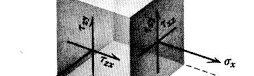
7 Considering Static Equilibrium of the element, we have * Normal and shear stress components acting on opposite sides of an element must be equal in magnitude and opposite in direction * Shear stress components satisfy moment equilibrium ; ; xy yx xz zx yz zy
8 PRINCIPAL STRESSES State of stress at a point in a material is completely defined by the stresses acting on the planes of a cubical volume element whose edges are parallel to coordinate directions. Often, it is important to determine the state of stress on a plane at some angle to the coordinate axes. Mostly, the state of stress on a plane on which no shear stresses act is important for design purposes. A plane, where no shear stresses act is called a principal plane and the normal stress that acts on such a plane is called principal stress.
9
10 Mohr s Circle - Its Use and Limitations Consider a stress state at a point is such that on one of the coordinate plane, there are no shear stresses and only normal stress (may be zero or not) is present. That normal stress is one of the principal i stress as shown in figure. You can see that on an plane perpendicular to z-axis only s z ( may be tensile, compressive or zero) is present. Then remaining two principal p stresses can be determined e ed using biaxial stress field and Mohr Circle. Biaxial stress field in xy-plane can be shown as above. Using stress transformation equation, the normal stress x along x axis and xy the shear stress (from last terms Mech. Of solids) can be written as. 1 1 x x y x ycos xysin 1 xy x ysin xycos (A) x will become principal stress if x y = 0. Using this condition, the remaining principal stresses can be determined as. 1 1 p x y x y xy and the orientation of the principal planes with respect to x- axis is given by xy tan x y
11 The same results can be expressed graphically using Mohr s Circle. Rearranging gthe equations (A), we obtain 1 1 x x y x ycos xysin 1 xy x y sin xycos Squaring the above equations, then adding, gives 1 1 x x y xy x y xy This is the equation of a circle whose center is at and whose radius is given by 1/ 1 x y xy 1 x y,0 Every point on the circle defines the stress state acting on planes at any angle q from the original x or y axis. For the correct construction of Mohr s circle, certain rules are followed and a consistent handling of positive and negative stress is essential, only if proper orientation of planes is desired. Nosuchconcernisrequired if only the magnitudes of the principal p stresses are sought. Although various conventions are in use, we follow the convention given in Hibbler Book. 1.Normal stresses are plotted to scale along the abscissa (horizontal axis) with tensile stresses considered positive and compressive stresses negative..shear stresses are plotted along the ordinate (vertical axis) with positive direction downward to the same scale as used for normal stresses. A shear stress that would tend to cause counter-clock wise rotation of the stress element in the physical plane is considered positive while negative shear stress tend to cause clockwise rotation.
12 3.Angle between lines of direction on the Mohr plot are twice the indicated angle on the physical plane. The angle ' on the Mohr circle is measured in the same direction as the angle for the orientation of the plane in physical plane. According definition, the values of corresponding to the points D and B (where = 0) are the principal stresses. The radius of the Mohr s circle gives the maximum in-plane shear stress Three -Dimensional Mohr s Plot As mentioned previously, Mohr s circle can be drawn to determine principal stresses only if one of the three principal stresses is known. Since the known principal stress is also a normal stress, it can be plotted on s axis and circles can be drawn between all the principal stresses as shown. then the maximum absolute shear stress is equal to radius of largest Mohr s circle. Absolute maximum shear stress is given as 1 max pmax p min
13
14 Static Failure Theories
15 x zx M *( d / ) M *( d / ) 3M 3* lb / in I d /64 d *(1.5) Tr T ( d / ) 16T 16* lb / in J ( d /3) d (1.5) v 4V 4V 4* lb / in 3 A 3( d /4) 3*( *(1.5) / 4) At Point A x z x z 1, 58184, lb / in max lb / in xz
16 At point B lb / in xy, 4904 lb / in 1 max 4904 lb / in
Stress transformation and Mohr s circle for stresses
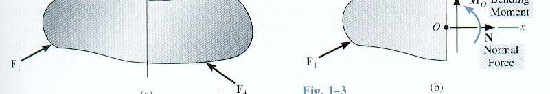
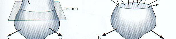
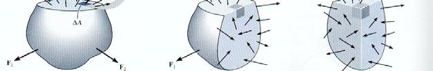
 Stress transformation and Mohr s circle for stresses 1.1 General State of stress Consider a certain body, subjected to external force. The force F is acting on the surface over an area da of the surface.
CHAPTER 4 Stress Transformation
 CHAPTER 4 Stress Transformation ANALYSIS OF STRESS For this topic, the stresses to be considered are not on the perpendicular and parallel planes only but also on other inclined planes. A P a a b b P z
Principal Stresses, Yielding Criteria, wall structures
 Principal Stresses, Yielding Criteria, St i thi Stresses in thin wall structures Introduction The most general state of stress at a point may be represented by 6 components, x, y, z τ xy, τ yz, τ zx normal
Prof. B V S Viswanadham, Department of Civil Engineering, IIT Bombay
 50 Module 4: Lecture 1 on Stress-strain relationship and Shear strength of soils Contents Stress state, Mohr s circle analysis and Pole, Principal stressspace, Stress pathsin p-q space; Mohr-Coulomb failure
Combined Stresses and Mohr s Circle. General Case of Combined Stresses. General Case of Combined Stresses con t. Two-dimensional stress condition
 Combined Stresses and Mohr s Circle Material in this lecture was taken from chapter 4 of General Case of Combined Stresses Two-dimensional stress condition General Case of Combined Stresses con t The normal
Stress, Strain, Mohr s Circle
 Stress, Strain, Mohr s Circle The fundamental quantities in solid mechanics are stresses and strains. In accordance with the continuum mechanics assumption, the molecular structure of materials is neglected
ME 243. Lecture 10: Combined stresses
 ME 243 Mechanics of Solids Lecture 10: Combined stresses Ahmad Shahedi Shakil Lecturer, Dept. of Mechanical Engg, BUET E-mail: sshakil@me.buet.ac.bd, shakil6791@gmail.com Website: teacher.buet.ac.bd/sshakil
ANALYSIS OF STERSSES. General State of stress at a point :
 ANALYSIS OF STERSSES General State of stress at a point : Stress at a point in a material body has been defined as a force per unit area. But this definition is some what ambiguous since it depends upon
9. Stress Transformation
 9.7 ABSOLUTE MAXIMUM SHEAR STRESS A pt in a body subjected to a general 3-D state of stress will have a normal stress and shear-stress components acting on each of its faces. We can develop stress-transformation
CHAPER THREE ANALYSIS OF PLANE STRESS AND STRAIN
 CHAPER THREE ANALYSIS OF PLANE STRESS AND STRAIN Introduction This chapter is concerned with finding normal and shear stresses acting on inclined sections cut through a member, because these stresses may
1 Stress and Strain. Introduction
 1 Stress and Strain Introduction This book is concerned with the mechanical behavior of materials. The term mechanical behavior refers to the response of materials to forces. Under load, a material may
3D Elasticity Theory
 3D lasticity Theory Many structural analysis problems are analysed using the theory of elasticity in which Hooke s law is used to enforce proportionality between stress and strain at any deformation level.
both an analytical approach and the pole method, determine: (a) the direction of the
 the direction of the") Quantitative Problems Problem 4-3 Figure 4-45 shows the state of stress at a point within a soil deposit. Using both an analytical approach and the pole method, determine: (a) the direction of the principal
Quantitative Problems Problem 4-3 Figure 4-45 shows the state of stress at a point within a soil deposit. Using both an analytical approach and the pole method, determine: (a) the direction of the principal
Stress Transformation Equations: u = +135 (Fig. a) s x = 80 MPa s y = 0 t xy = 45 MPa. we obtain, cos u + t xy sin 2u. s x = s x + s y.
 s x = 80 MPa s y = 0 t xy = 45 MPa. we obtain, cos u + t xy sin 2u. s x = s x + s y.") 014 Pearson Education, Inc., Upper Saddle River, NJ. All rights reserved. This material is protected under all copyright laws as they currently 9 7. Determine the normal stress and shear stress acting
014 Pearson Education, Inc., Upper Saddle River, NJ. All rights reserved. This material is protected under all copyright laws as they currently 9 7. Determine the normal stress and shear stress acting
Strain Transformation equations
 Strain Transformation equations R. Chandramouli Associate Dean-Research SASTRA University, Thanjavur-613 401 Joint Initiative of IITs and IISc Funded by MHRD Page 1 of 8 Table of Contents 1. Stress transformation
ENR202 Mechanics of Materials Lecture 12B Slides and Notes
 ENR0 Mechanics of Materials Lecture 1B Slides and Notes Slide 1 Copright Notice Do not remove this notice. COMMMONWEALTH OF AUSTRALIA Copright Regulations 1969 WARNING This material has been produced and
Two Dimensional State of Stress and Strain: examples
 Lecture 1-5: Two Dimensional State of Stress and Strain: examples Principal stress. Stresses on oblique plane: Till now we have dealt with either pure normal direct stress or pure shear stress. In many
MECH 5312 Solid Mechanics II. Dr. Calvin M. Stewart Department of Mechanical Engineering The University of Texas at El Paso
 MECH 5312 Solid Mechanics II Dr. Calvin M. Stewart Department of Mechanical Engineering The University of Texas at El Paso Table of Contents Preliminary Math Concept of Stress Stress Components Equilibrium
The hitch in all of this is figuring out the two principal angles and which principal stress goes with which principal angle.
 Mohr s Circle The stress basic transformation equations that we developed allowed us to determine the stresses acting on an element regardless of its orientation as long as we know the basic stresses σx,
ANALYSIS OF STRAINS CONCEPT OF STRAIN
 ANALYSIS OF STRAINS CONCEPT OF STRAIN Concept of strain : if a bar is subjected to a direct load, and hence a stress the bar will change in length. If the bar has an original length L and changes by an
Unit IV State of stress in Three Dimensions
 Unit IV State of stress in Three Dimensions State of stress in Three Dimensions References Punmia B.C.,"Theory of Structures" (SMTS) Vol II, Laxmi Publishing Pvt Ltd, New Delhi 2004. Rattan.S.S., "Strength
MECE 3321 MECHANICS OF SOLIDS CHAPTER 1
 MECE 3321 MECHANICS O SOLIDS CHAPTER 1 Samantha Ramirez, MSE WHAT IS MECHANICS O MATERIALS? Rigid Bodies Statics Dynamics Mechanics Deformable Bodies Solids/Mech. Of Materials luids 1 WHAT IS MECHANICS
BOOK OF COURSE WORKS ON STRENGTH OF MATERIALS FOR THE 2 ND YEAR STUDENTS OF THE UACEG
 BOOK OF COURSE WORKS ON STRENGTH OF MATERIALS FOR THE ND YEAR STUDENTS OF THE UACEG Assoc.Prof. Dr. Svetlana Lilkova-Markova, Chief. Assist. Prof. Dimitar Lolov Sofia, 011 STRENGTH OF MATERIALS GENERAL
ELASTICITY (MDM 10203)
") ELASTICITY () Lecture Module 3: Fundamental Stress and Strain University Tun Hussein Onn Malaysia Normal Stress inconstant stress distribution σ= dp da P = da A dimensional Area of σ and A σ A 3 dimensional
ELASTICITY () Lecture Module 3: Fundamental Stress and Strain University Tun Hussein Onn Malaysia Normal Stress inconstant stress distribution σ= dp da P = da A dimensional Area of σ and A σ A 3 dimensional
Dynamics of Machinery
 1 Preamble Dynamics of Machinery Relation between motion and forces causing is a fascinating subject. This study is a generally referred as dynamic. Modern Engineering aims at analysing and predicting
MECH 401 Mechanical Design Applications
 MECH 401 Mechanical Design Applications Dr. M. O Malley Master Notes Spring 008 Dr. D. M. McStravick Rice University Updates HW 1 due Thursday (1-17-08) Last time Introduction Units Reliability engineering
Mohr's Circle for 2-D Stress Analysis
 Mohr's Circle for 2-D Stress Analysis If you want to know the principal stresses and maximum shear stresses, you can simply make it through 2-D or 3-D Mohr's cirlcles! You can know about the theory of
7. STRESS ANALYSIS AND STRESS PATHS
 7-1 7. STRESS ANALYSIS AND STRESS PATHS 7.1 THE MOHR CIRCLE The discussions in Chapters and 5 were largely concerned with vertical stresses. A more detailed examination of soil behaviour requires a knowledge
[5] Stress and Strain
![[5] Stress and Strain](/thumbs/95/123344550.jpg "[5] Stress and Strain") [5] Stress and Strain Page 1 of 34 [5] Stress and Strain [5.1] Internal Stress of Solids [5.2] Design of Simple Connections (will not be covered in class) [5.3] Deformation and Strain [5.4] Hooke s Law
[5] Stress and Strain Page 1 of 34 [5] Stress and Strain [5.1] Internal Stress of Solids [5.2] Design of Simple Connections (will not be covered in class) [5.3] Deformation and Strain [5.4] Hooke s Law
x y plane is the plane in which the stresses act, yy xy xy Figure 3.5.1: non-zero stress components acting in the x y plane
 3.5 Plane Stress This section is concerned with a special two-dimensional state of stress called plane stress. It is important for two reasons: () it arises in real components (particularl in thin components
Introduction. 1.1 Introduction. 1.2 Trigonometrical definitions
 Introduction 1.1 Introduction Stress analysis is an important part of engineering science, as failure of most engineering components is usually due to stress. The component under a stress investigation
In this section, mathematical description of the motion of fluid elements moving in a flow field is
 Jun. 05, 015 Chapter 6. Differential Analysis of Fluid Flow 6.1 Fluid Element Kinematics In this section, mathematical description of the motion of fluid elements moving in a flow field is given. A small
EE C247B ME C218 Introduction to MEMS Design Spring 2017
 247B/M 28: Introduction to MMS Design Lecture 0m2: Mechanics of Materials CTN 2/6/7 Outline C247B M C28 Introduction to MMS Design Spring 207 Prof. Clark T.- Reading: Senturia, Chpt. 8 Lecture Topics:
Mechanics of Earthquakes and Faulting
 Mechanics of Earthquakes and Faulting www.geosc.psu.edu/courses/geosc508 Overview Milestones in continuum mechanics Concepts of modulus and stiffness. Stress-strain relations Elasticity Surface and body
MECHANICS OF MATERIALS
 009 The McGraw-Hill Companies, Inc. All rights reserved. Fifth SI Edition CHAPTER 7 MECHANICS OF MATERIALS Ferdinand P. Beer E. Russell Johnston, Jr. John T. DeWolf David F. Mazurek Transformations of
VYSOKÁ ŠKOLA BÁŇSKÁ TECHNICKÁ UNIVERZITA OSTRAVA
 VYSOKÁ ŠKOLA BÁŇSKÁ TECHNICKÁ UNIVERZITA OSTRAVA FAKULTA METALURGIE A MATERIÁLOVÉHO INŽENÝRSTVÍ APPLIED MECHANICS Study Support Leo Václavek Ostrava 2015 Title:Applied Mechanics Code: Author: doc. Ing.
Prof. B V S Viswanadham, Department of Civil Engineering, IIT Bombay
 51 Module 4: Lecture 2 on Stress-strain relationship and Shear strength of soils Contents Stress state, Mohr s circle analysis and Pole, Principal stressspace, Stress pathsin p-q space; Mohr-coulomb failure
Review Lecture. AE1108-II: Aerospace Mechanics of Materials. Dr. Calvin Rans Dr. Sofia Teixeira De Freitas
 Review Lecture AE1108-II: Aerospace Mechanics of Materials Dr. Calvin Rans Dr. Sofia Teixeira De Freitas Aerospace Structures & Materials Faculty of Aerospace Engineering Analysis of an Engineering System
Module #3. Transformation of stresses in 3-D READING LIST. DIETER: Ch. 2, pp Ch. 3 in Roesler Ch. 2 in McClintock and Argon Ch.
 HOMEWORK From Dieter -3, -4, 3-7 Module #3 Transformation of stresses in 3-D READING LIST DIETER: Ch., pp. 7-36 Ch. 3 in Roesler Ch. in McClintock and Argon Ch. 7 in Edelglass The Stress Tensor z z x O
CH.4. STRESS. Continuum Mechanics Course (MMC)
") CH.4. STRESS Continuum Mechanics Course (MMC) Overview Forces Acting on a Continuum Body Cauchy s Postulates Stress Tensor Stress Tensor Components Scientific Notation Engineering Notation Sign Criterion
CH.4. STRESS Continuum Mechanics Course (MMC) Overview Forces Acting on a Continuum Body Cauchy s Postulates Stress Tensor Stress Tensor Components Scientific Notation Engineering Notation Sign Criterion
Failure from static loading
 Failure from static loading Topics Quiz /1/07 Failures from static loading Reading Chapter 5 Homework HW 3 due /1 HW 4 due /8 What is Failure? Failure any change in a machine part which makes it unable
Mechanics of Earthquakes and Faulting
 Mechanics of Earthquakes and Faulting www.geosc.psu.edu/courses/geosc508 Surface and body forces Tensors, Mohr circles. Theoretical strength of materials Defects Stress concentrations Griffith failure
Pressure Vessels Stresses Under Combined Loads Yield Criteria for Ductile Materials and Fracture Criteria for Brittle Materials
 Pressure Vessels Stresses Under Combined Loads Yield Criteria for Ductile Materials and Fracture Criteria for Brittle Materials Pressure Vessels: In the previous lectures we have discussed elements subjected
(Refer Slide Time: 04:21 min)
") Soil Mechanics Prof. B.V.S. Viswanathan Department of Civil Engineering Indian Institute of Technology, Bombay Lecture 44 Shear Strength of Soils Lecture No.2 Dear students today we shall go through yet
Soil Mechanics Prof. B.V.S. Viswanathan Department of Civil Engineering Indian Institute of Technology, Bombay Lecture 44 Shear Strength of Soils Lecture No.2 Dear students today we shall go through yet
Name (Print) ME Mechanics of Materials Exam # 1 Date: October 5, 2016 Time: 8:00 10:00 PM
 ME Mechanics of Materials Exam # 1 Date: October 5, 2016 Time: 8:00 10:00 PM") Name (Print) (Last) (First) Instructions: ME 323 - Mechanics of Materials Exam # 1 Date: October 5, 2016 Time: 8:00 10:00 PM Circle your lecturer s name and your class meeting time. Gonzalez Krousgrill
Name (Print) (Last) (First) Instructions: ME 323 - Mechanics of Materials Exam # 1 Date: October 5, 2016 Time: 8:00 10:00 PM Circle your lecturer s name and your class meeting time. Gonzalez Krousgrill
GG303 Lecture 17 10/25/09 1 MOHR CIRCLE FOR TRACTIONS
 GG303 Lecture 17 10/5/09 1 MOHR CIRCLE FOR TRACTIONS I Main Topics A Stresses vs. tractions B Mohr circle for tractions II Stresses vs. tractions A Similarities between stresses and tractions 1 Same dimensions
2. (i) Find the equation of the circle which passes through ( 7, 1) and has centre ( 4, 3).
 Find the equation of the circle which passes through ( 7, 1) and has centre ( 4, 3).") Circle 1. (i) Find the equation of the circle with centre ( 7, 3) and of radius 10. (ii) Find the centre of the circle 2x 2 + 2y 2 + 6x + 8y 1 = 0 (iii) What is the radius of the circle 3x 2 + 3y 2 + 5x
Circle 1. (i) Find the equation of the circle with centre ( 7, 3) and of radius 10. (ii) Find the centre of the circle 2x 2 + 2y 2 + 6x + 8y 1 = 0 (iii) What is the radius of the circle 3x 2 + 3y 2 + 5x
MECHANICS OF MATERIALS
 00 The McGraw-Hill Companies, Inc. All rights reserved. T Edition CHAPTER MECHANICS OF MATERIALS Ferdinand P. Beer E. Russell Johnston, Jr. John T. DeWolf Lecture Notes: J. Walt Oler Teas Tech Universit
Jeff Brown Hope College, Department of Engineering, 27 Graves Pl., Holland, Michigan, USA UNESCO EOLSS
 MECHANICS OF MATERIALS Jeff Brown Hope College, Department of Engineering, 27 Graves Pl., Holland, Michigan, USA Keywords: Solid mechanics, stress, strain, yield strength Contents 1. Introduction 2. Stress
D : SOLID MECHANICS. Q. 1 Q. 9 carry one mark each. Q.1 Find the force (in kn) in the member BH of the truss shown.
 in the member BH of the truss shown.") D : SOLID MECHANICS Q. 1 Q. 9 carry one mark each. Q.1 Find the force (in kn) in the member BH of the truss shown. Q.2 Consider the forces of magnitude F acting on the sides of the regular hexagon having
D : SOLID MECHANICS Q. 1 Q. 9 carry one mark each. Q.1 Find the force (in kn) in the member BH of the truss shown. Q.2 Consider the forces of magnitude F acting on the sides of the regular hexagon having
Continuum mechanism: Stress and strain
 Continuum mechanics deals with the relation between forces (stress, σ) and deformation (strain, ε), or deformation rate (strain rate, ε). Solid materials, rigid, usually deform elastically, that is the
2. Mechanics of Materials: Strain. 3. Hookes's Law
 Mechanics of Materials Course: WB3413, Dredging Processes 1 Fundamental Theory Required for Sand, Clay and Rock Cutting 1. Mechanics of Materials: Stress 1. Introduction 2. Plane Stress and Coordinate
Name (Print) ME Mechanics of Materials Exam # 3 Date: December 9, 2013 Time: 7:00 9:00 PM Location: EE 129 & EE170
 ME Mechanics of Materials Exam # 3 Date: December 9, 2013 Time: 7:00 9:00 PM Location: EE 129 & EE170") Name (Print) (Last) (First) Instructions: ME 323 - Mechanics of Materials Exam # 3 Date: December 9, 2013 Time: 7:00 9:00 PM Location: EE 129 & EE170 Circle your lecturer s name and your class meeting
Name (Print) (Last) (First) Instructions: ME 323 - Mechanics of Materials Exam # 3 Date: December 9, 2013 Time: 7:00 9:00 PM Location: EE 129 & EE170 Circle your lecturer s name and your class meeting
LIMITATIONS OF THE STANDARD INTERACTION FORMULA FOR BIAXIAL BENDING AS APPLIED TO RECTANGULAR STEEL TUBULAR COLUMNS
 LIMITATIONS OF THE STANDARD INTERACTION FORMULA FOR BIAXIAL BENDING AS APPLIED TO RECTANGULAR STEEL TUBULAR COLUMNS Ramon V. Jarquio 1 ABSTRACT The limitations of the standard interaction formula for biaxial
Engineering Mechanics Department of Mechanical Engineering Dr. G. Saravana Kumar Indian Institute of Technology, Guwahati
 Engineering Mechanics Department of Mechanical Engineering Dr. G. Saravana Kumar Indian Institute of Technology, Guwahati Module 3 Lecture 6 Internal Forces Today, we will see analysis of structures part
MEMS Project 2 Assignment. Design of a Shaft to Transmit Torque Between Two Pulleys
 MEMS 029 Project 2 Assignment Design of a Shaft to Transmit Torque Between Two Pulleys Date: February 5, 206 Instructor: Dr. Stephen Ludwick Product Definition Shafts are incredibly important in order
Review for Exam 1. (a) Find an equation of the line through the point ( 2, 4, 10) and parallel to the vector
 Find an equation of the line through the point ( 2, 4, 10) and parallel to the vector") Calculus 3 Lia Vas Review for Exam 1 1. Surfaces. Describe the following surfaces. (a) x + y = 9 (b) x + y + z = 4 (c) z = 1 (d) x + 3y + z = 6 (e) z = x + y (f) z = x + y. Review of Vectors. (a) Let a
Calculus 3 Lia Vas Review for Exam 1 1. Surfaces. Describe the following surfaces. (a) x + y = 9 (b) x + y + z = 4 (c) z = 1 (d) x + 3y + z = 6 (e) z = x + y (f) z = x + y. Review of Vectors. (a) Let a
Chapter 3. Load and Stress Analysis
 Chapter 3 Load and Stress Analysis 2 Shear Force and Bending Moments in Beams Internal shear force V & bending moment M must ensure equilibrium Fig. 3 2 Sign Conventions for Bending and Shear Fig. 3 3
Bone Tissue Mechanics
 Bone Tissue Mechanics João Folgado Paulo R. Fernandes Instituto Superior Técnico, 2016 PART 1 and 2 Introduction The objective of this course is to study basic concepts on hard tissue mechanics. Hard tissue
Eigen decomposition for 3D stress tensor
 Eigen decomposition for 3D stress tensor by Vince Cronin Begun September 13, 2010; last revised September 23, 2015 Unfinished Dra ; Subject to Revision Introduction If we have a cubic free body that is
Sports biomechanics explores the relationship between the body motion, internal forces and external forces to optimize the sport performance.
 What is biomechanics? Biomechanics is the field of study that makes use of the laws of physics and engineering concepts to describe motion of body segments, and the internal and external forces, which
Tutorial #1 - CivE. 205 Name: I.D:
 Tutorial # - CivE. 0 Name: I.D: Eercise : For the Beam below: - Calculate the reactions at the supports and check the equilibrium of point a - Define the points at which there is change in load or beam
V (r,t) = i ˆ u( x, y,z,t) + ˆ j v( x, y,z,t) + k ˆ w( x, y, z,t)
 = i ˆ u( x, y,z,t) + ˆ j v( x, y,z,t) + k ˆ w( x, y, z,t)") IV. DIFFERENTIAL RELATIONS FOR A FLUID PARTICLE This chapter presents the development and application of the basic differential equations of fluid motion. Simplifications in the general equations and common
IV. DIFFERENTIAL RELATIONS FOR A FLUID PARTICLE This chapter presents the development and application of the basic differential equations of fluid motion. Simplifications in the general equations and common
Material subjected to combined direct and shear stresses:
 Material subjected to combined direct and shear stresses: Now consider a complex stress system shown below, acting on an element of material. The stresses x and y may be compressive or tensile and may
7. Design of pressure vessels and Transformation of plane stress Contents
 7. Design of pressure vessels and Transformation of plane stress Contents 7. Design of pressure vessels and Transformation of plane stress... 1 7.1 Introduction... 7. Design of pressure vessels... 7..1
ENGINEERING OF NUCLEAR REACTORS NOTE L.4 INTRODUCTION TO STRUCTURAL MECHANICS. Lothar Wolf, Mujid S. Kazimi and Neil E.
 .31 ENGINEERING OF NUCLEAR REACTORS NOTE L.4 INTRODUCTION TO STRUCTURAL MECHANICS Lothar Wolf, Mujid S. Kazimi and Neil E. Todreas Nominal Load Point 35 55 6569 100 σ 1-5 -45-57.7-60 Max τ theory DE theory
Unit Workbook 1 Level 4 ENG U8 Mechanical Principles 2018 UniCourse Ltd. All Rights Reserved. Sample
 Pearson BTEC Levels 4 Higher Nationals in Engineering (RQF) Unit 8: Mechanical Principles Unit Workbook 1 in a series of 4 for this unit Learning Outcome 1 Static Mechanical Systems Page 1 of 23 1.1 Shafts
ME Machine Design I
 ME 5 - Machine Design I Summer Semester 008 Name Lab. Div. EXAM. OEN BOOK AND CLOSED NOTES. Wednesday, July 16th, 008 Write your solutions on the blank paper that is provided. Write on one side of the
Spherical Pressure Vessels
 Spherical Pressure Vessels Pressure vessels are closed structures containing liquids or gases under essure. Examples include tanks, pipes, essurized cabins, etc. Shell structures : When essure vessels
Problem " Â F y = 0. ) R A + 2R B + R C = 200 kn ) 2R A + 2R B = 200 kn [using symmetry R A = R C ] ) R A + R B = 100 kn
![Problem  F y = 0. ) R A + 2R B + R C = 200 kn ) 2R A + 2R B = 200 kn [using symmetry R A = R C ] ) R A + R B = 100 kn](/thumbs/88/116790835.jpg "Problem  F y = 0. ) R A + 2R B + R C = 200 kn ) 2R A + 2R B = 200 kn [using symmetry R A = R C ] ) R A + R B = 100 kn") Problem 0. Three cables are attached as shown. Determine the reactions in the supports. Assume R B as redundant. Also, L AD L CD cos 60 m m. uation of uilibrium: + "  F y 0 ) R A cos 60 + R B + R C cos
Problem 0. Three cables are attached as shown. Determine the reactions in the supports. Assume R B as redundant. Also, L AD L CD cos 60 m m. uation of uilibrium: + " Â F y 0 ) R A cos 60 + R B + R C cos
Lecture 8. Stress Strain in Multi-dimension
 Lecture 8. Stress Strain in Multi-dimension Module. General Field Equations General Field Equations [] Equilibrium Equations in Elastic bodies xx x y z yx zx f x 0, etc [2] Kinematics xx u x x,etc. [3]
THE CAUSES: MECHANICAL ASPECTS OF DEFORMATION
 17 THE CAUSES: MECHANICAL ASPECTS OF DEFORMATION Mechanics deals with the effects of forces on bodies. A solid body subjected to external forces tends to change its position or its displacement or its
Foundation Analysis LATERAL EARTH PRESSURE
 Foundation Analysis LATERAL EARTH PRESSURE INTRODUCTION Vertical or near-vertical slopes of soil are supported by retaining walls, cantilever sheet-pile walls, sheet-pile bulkheads, braced cuts, and other
AE/ME 339. Computational Fluid Dynamics (CFD) K. M. Isaac. Momentum equation. Computational Fluid Dynamics (AE/ME 339) MAEEM Dept.
 K. M. Isaac. Momentum equation. Computational Fluid Dynamics (AE/ME 339) MAEEM Dept.") AE/ME 339 Computational Fluid Dynamics (CFD) 9//005 Topic7_NS_ F0 1 Momentum equation 9//005 Topic7_NS_ F0 1 Consider the moving fluid element model shown in Figure.b Basis is Newton s nd Law which says
AE/ME 339 Computational Fluid Dynamics (CFD) 9//005 Topic7_NS_ F0 1 Momentum equation 9//005 Topic7_NS_ F0 1 Consider the moving fluid element model shown in Figure.b Basis is Newton s nd Law which says
BTECH MECHANICAL PRINCIPLES AND APPLICATIONS. Level 3 Unit 5
 BTECH MECHANICAL PRINCIPLES AND APPLICATIONS Level 3 Unit 5 FORCES AS VECTORS Vectors have a magnitude (amount) and a direction. Forces are vectors FORCES AS VECTORS (2 FORCES) Forces F1 and F2 are in
ARC 341 Structural Analysis II. Lecture 10: MM1.3 MM1.13
 ARC241 Structural Analysis I Lecture 10: MM1.3 MM1.13 MM1.4) Analysis and Design MM1.5) Axial Loading; Normal Stress MM1.6) Shearing Stress MM1.7) Bearing Stress in Connections MM1.9) Method of Problem
3.22 Mechanical Properties of Materials Spring 2008
 MIT OpenCourseWare http://ocw.mit.edu 3.22 Mechanical Properties of Materials Spring 2008 For information about citing these materials or our Terms of Use, visit: http://ocw.mit.edu/terms. Quiz #1 Example
STRESS. Bar. ! Stress. ! Average Normal Stress in an Axially Loaded. ! Average Shear Stress. ! Allowable Stress. ! Design of Simple Connections
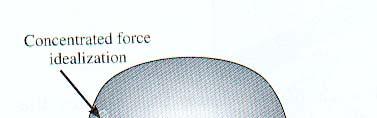
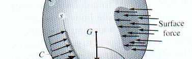
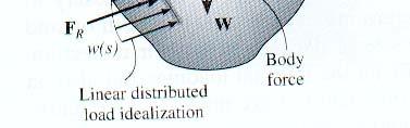
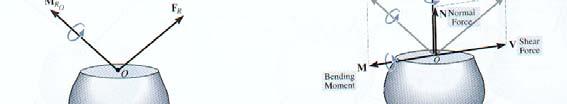
 STRESS! Stress Evisdom! verage Normal Stress in an xially Loaded ar! verage Shear Stress! llowable Stress! Design of Simple onnections 1 Equilibrium of a Deformable ody ody Force w F R x w(s). D s y Support
SIGN CONVENTION OF STRESS RESULTANTS
 SIGN CONVENTION OF STRESS RESULTANTS A quick guide to understanding the sign conventions used in the ush Me ull Me models National HE STEM rogramme INTRODUCTION Representing stress resultants graphically
MECHANICS OF MATERIALS
 CHAPTER MECHANICS OF MATERIALS Ferdinand P. Beer E. Russell Johnston, Jr. John T. DeWolf Lecture Notes: J. Walt Oler Teas Tech Universit Transformations of Stress and Strain 006 The McGraw-Hill Companies,
SHEAR STRENGTH OF SOIL. Chapter 10: Sections Chapter 12: All sections except
 SHEAR STRENGTH OF SOIL Chapter 10: Sections 10. 10.3 Chapter 1: All sections ecept 1.13 1.14 1.15 1.17 1.18 TOPICS Introduction Components of Shear Strength of Soils Normal and Shear Stresses on a Plane
Mechanics of Solids (APJ ABDUL KALAM TECHNOLOGICAL UNIVERSITY) And As per Revised Syllabus of Leading Universities in India AIR WALK PUBLICATIONS
 And As per Revised Syllabus of Leading Universities in India AIR WALK PUBLICATIONS") Advanced Mechanics of Solids (APJ ABDUL KALAM TECHNOLOGICAL UNIVERSITY) And As per Revised Syllabus of Leading Universities in India Dr. S. Ramachandran Prof. R. Devaraj Professors School of Mechanical
Advanced Mechanics of Solids (APJ ABDUL KALAM TECHNOLOGICAL UNIVERSITY) And As per Revised Syllabus of Leading Universities in India Dr. S. Ramachandran Prof. R. Devaraj Professors School of Mechanical
Tensor Transformations and the Maximum Shear Stress. (Draft 1, 1/28/07)
") Tensor Transformations and the Maximum Shear Stress (Draft 1, 1/28/07) Introduction The order of a tensor is the number of subscripts it has. For each subscript it is multiplied by a direction cosine array
Tensor Transformations and the Maximum Shear Stress (Draft 1, 1/28/07) Introduction The order of a tensor is the number of subscripts it has. For each subscript it is multiplied by a direction cosine array
Use Hooke s Law (as it applies in the uniaxial direction),
,") 0.6 STRSS-STRAIN RLATIONSHIP Use the principle of superposition Use Poisson s ratio, v lateral longitudinal Use Hooke s Law (as it applies in the uniaxial direction), x x v y z, y y vx z, z z vx y Copyright
0.6 STRSS-STRAIN RLATIONSHIP Use the principle of superposition Use Poisson s ratio, v lateral longitudinal Use Hooke s Law (as it applies in the uniaxial direction), x x v y z, y y vx z, z z vx y Copyright
Free-Body Diagrams. Introduction
 Free-Body Diagrams Introduction A Free-Body Diagram is a basic two or three-dimensional representation of an object used to show all present forces and moments. The purpose of the diagram is to deconstruct
STRAIN. Normal Strain: The elongation or contractions of a line segment per unit length is referred to as normal strain denoted by Greek symbol.
 STRAIN In engineering the deformation of a body is specified using the concept of normal strain and shear strain whenever a force is applied to a body, it will tend to change the body s shape and size.
(Refer Slide Time: 2:43-03:02)
") Strength of Materials Prof. S. K. Bhattacharyya Department of Civil Engineering Indian Institute of Technology, Kharagpur Lecture - 34 Combined Stresses I Welcome to the first lesson of the eighth module
Strength of Materials Prof. S. K. Bhattacharyya Department of Civil Engineering Indian Institute of Technology, Kharagpur Lecture - 34 Combined Stresses I Welcome to the first lesson of the eighth module
10.2,3,4. Vectors in 3D, Dot products and Cross Products
 Name: Section: 10.2,3,4. Vectors in 3D, Dot products and Cross Products 1. Sketch the plane parallel to the xy-plane through (2, 4, 2) 2. For the given vectors u and v, evaluate the following expressions.
Name (Print) ME Mechanics of Materials Exam # 2 Date: March 29, 2016 Time: 8:00 10:00 PM - Location: PHYS 114
 ME Mechanics of Materials Exam # 2 Date: March 29, 2016 Time: 8:00 10:00 PM - Location: PHYS 114") Name (Print) (Last) (First) Instructions: ME 323 - Mechanics of Materials Exam # 2 Date: March 29, 2016 Time: 8:00 10:00 PM - Location: PHYS 114 Circle your lecturer s name and your class meeting time.
Name (Print) (Last) (First) Instructions: ME 323 - Mechanics of Materials Exam # 2 Date: March 29, 2016 Time: 8:00 10:00 PM - Location: PHYS 114 Circle your lecturer s name and your class meeting time.
D : SOLID MECHANICS. Q. 1 Q. 9 carry one mark each.
 GTE 2016 Q. 1 Q. 9 carry one mark each. D : SOLID MECHNICS Q.1 single degree of freedom vibrating system has mass of 5 kg, stiffness of 500 N/m and damping coefficient of 100 N-s/m. To make the system
S12.1 SOLUTIONS TO PROBLEMS 12 (ODD NUMBERS)
") OLUTION TO PROBLEM 2 (ODD NUMBER) 2. The electric field is E = φ = 2xi + 2y j and at (2, ) E = 4i + 2j. Thus E = 2 5 and its direction is 2i + j. At ( 3, 2), φ = 6i + 4 j. Thus the direction of most rapid
OLUTION TO PROBLEM 2 (ODD NUMBER) 2. The electric field is E = φ = 2xi + 2y j and at (2, ) E = 4i + 2j. Thus E = 2 5 and its direction is 2i + j. At ( 3, 2), φ = 6i + 4 j. Thus the direction of most rapid
UNIVERSITY OF SASKATCHEWAN ME MECHANICS OF MATERIALS I FINAL EXAM DECEMBER 13, 2008 Professor A. Dolovich
 UNIVERSITY OF SASKATCHEWAN ME 313.3 MECHANICS OF MATERIALS I FINAL EXAM DECEMBER 13, 2008 Professor A. Dolovich A CLOSED BOOK EXAMINATION TIME: 3 HOURS For Marker s Use Only LAST NAME (printed): FIRST
Properties of the stress tensor
 Appendix C Properties of the stress tensor Some of the basic properties of the stress tensor and traction vector are reviewed in the following. C.1 The traction vector Let us assume that the state of stress
12. Stresses and Strains
 12. Stresses and Strains Finite Element Method Differential Equation Weak Formulation Approximating Functions Weighted Residuals FEM - Formulation Classification of Problems Scalar Vector 1-D T(x) u(x)
CLASS NOTES Version 5.0
 MAE 477/577 - EXPERIMENTAL TECHNIQUES IN SOLID MECHANICS - CLASS NOTES Version 5.0 by John A. Gilbert, Ph.D. Professor of Mechanical Engineering University of Alabama in Huntsville FALL 2013 Table of Contents
+ f f n x n. + (x)
") Math 255 - Vector Calculus II Notes 14.5 Divergence, (Grad) and Curl For a vector field in R n, that is F = f 1, f 2,..., f n, where f i is a function of x 1, x 2,..., x n, the divergence is div(f) = f
Math 255 - Vector Calculus II Notes 14.5 Divergence, (Grad) and Curl For a vector field in R n, that is F = f 1, f 2,..., f n, where f i is a function of x 1, x 2,..., x n, the divergence is div(f) = f
Chapter 4 Force System Resultant Moment of a Force
 Chapter 4 Force System Resultant Moment of a Force MOMENT OF A FORCE SCALAR FORMULATION, CROSS PRODUCT, MOMENT OF A FORCE VECTOR FORMULATION, & PRINCIPLE OF MOMENTS Today s Objectives : Students will be
Determination of Locally Varying Directions through Mass Moment of Inertia Tensor
 Determination of Locally Varying Directions through Mass Moment of Inertia Tensor R. M. Hassanpour and C.V. Deutsch Centre for Computational Geostatistics Department of Civil and Environmental Engineering
Lecture Triaxial Stress and Yield Criteria. When does yielding occurs in multi-axial stress states?
 Lecture 5.11 Triaial Stress and Yield Criteria When does ielding occurs in multi-aial stress states? Representing stress as a tensor operational stress sstem Compressive stress sstems Triaial stresses:
Basic Equations of Elasticity
 A Basic Equations of Elasticity A.1 STRESS The state of stress at any point in a loaded bo is defined completely in terms of the nine components of stress: σ xx,σ yy,σ zz,σ xy,σ yx,σ yz,σ zy,σ zx,andσ