Pulse Shaping and ISI (Proakis: chapter 10.1, 10.3) EEE3012 Spring 2018
|
|
|
- Dorcas McDowell
- 5 years ago
- Views:
Transcription
1 Pulse Shaping and ISI (Proakis: chapter 10.1, 10.3) EEE3012 Spring 2018
2 Digital Communication System
3 Introduction Bandlimited channels distort signals the result is smeared pulses intersymol interference (ISI) efore after ISI reduces the noise margin
4 Baseand Pulse Transmission Pulse shaping can control the ISI Î k { 0,1} pulse shaping transmit filter channel xt () G( jw ) H ( jw ) H ( jw) T c () yt H jw decision R ( ) receive filter sample ì+ a if k = 1 xt ( ) = å Agt k ( - kt) ; A ï k =í k ïî ï- a if k = 0 polar signaling
5 å () = ( - ) xt Agt kt k k Î k { 0,1} pulse shaping transmit filter channel x() t G ( jw ) H ( jw ) H ( jw ) T c ( ) a ( ) = å k - k y t A p t kt ( ) ( ) ( ) ( ) ( ) a P f = G f H f H f H f ( ) p 0 = 1 T R C () yt H jw decision R ( ) receive filter sample y(t) is sampled at t=nt ( ) a a ( ) ynt = A + å ApnT- kt contriution from the nth it n k k¹ n this is the ISI
6 to have zero ISI, we need ( ) a é ( ) ISI = a å A a é kp nt- kt = åakp n k T ù ë - û = 0 k¹ n k¹ n this happens with many pulse shapes consider a sinc( ) pulse ( ) = sinc ( t/ T ) pt / ( ) P jw t/ T - /2 /2 w o w o
7 A series of sinc pulses corresponding to the sequence

8 Is this a good pulse shape? No! A small amount of timing jitter can result in a great deal of ISI. Also ifiit infinite duration non-causal
9 Nyquist s First Criterion for Zero ISI To have zero ISI, we need ( ) pt ì 1 t = 0 = ï í ï ïî t= nt 0 if p(t) is sampled y an impulse train, then ( t ) d ( t- T ) = d ( t ) å ptåd t nt d t n known as the zero-forcing criterion often a goal of equalizers
10 ( ) d ( - ) = d ( ) å pt t nt t n taking the Fourier transform gives ( ) P f 1 n * åd æ f ö - = 1 T ç è T ø k P( jw) ( ) å P f - nf = T f = 1/ k Nyquist s First Criterion T w T - w w /2 w w
11 assuming that P(f)=0, f > f = 1/T gives ( ) ( ) 0 P f + P f - f = T < f < f P( w ) ( - ) P w w this happens when w /2 P( w) fold over and add w /2
12 P( w) cont /2 w form an equivalent pulse y folding over at f /2 zero ISI if the result is rectangular Peq ( w) w /2 the minimum andwidth Nyquist-1 pulse is clearly æ ö sinc t sinc ç èt ø ( ) = i = i [ f t ] p t
13 Roll-Off Factor Letting the pulse BW grow gives flexiility how does the pulse BW affect the eye? narrower andwidth more ringing in the time domain narrower eyes (in general) the roll-offoff factor parameterizes the BW ( ) P f g g = = f /2 excess andwidth /2 2g f f 2 f f [Hz] also commonly called a
14 Raised Cosine Pulses A family of pulse shapes with different s invented y Nyquist ~ 1928 cos ( pt/ T ) ( ) = 2 1- ( 2 t / T ) p t 1 2 / sinc / ( t T )
15 In the frequency domain 1- ìï T f 2 T T P( f) = í ï é1+ cos é f - ùù < f 2 ê ë ê ë ú û ûú 1+ ï 0 f 2T ïî T 2T 2T
16 Eye Diagram Effectively shows the effects of ISI extract each symol period plot on top of each other
17
18 Easy to show on a scope f efore and after pre-distortion ti

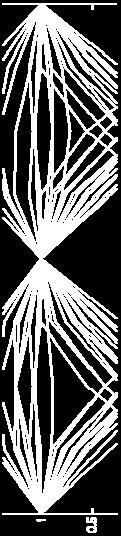

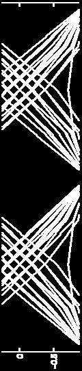

19 Interpretation width wasted power slope indicates sensitivity to timing errors noise tolerance zero crossing variation
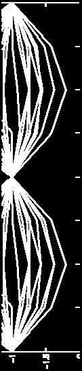
20 Works for multi-level systems consider a 4-level system where should the slicing levels go?
21 Need pulse shapes that give OPEN eyes the sinc pulse is not one of these!
22 Examples (1) What is the eye diagram RC 1 + j w RC pt ( ) RC= T we have full width pulses and polar signaling strategy? find the filter pulse response & superimpose
23 the step response is -t/ RC -t/ T ( ) = 1 - = 1 -, ³ 0 st e e t the pulse response is 1 ( ) ( - / ) ( - ( - )/ ) p t = 1 -e u( t) - 1 -e u( t-t ) t T t T T T 2T 3T assume zero after 3 time constants
24 the filtered data look at all the ISI! T 2T 3T find the resultant
25 T 2T 3T T 2T 3T eye the est sampling time is clearly at t = nt

- 1 -e ut ( -T ) t")
 ( -T / T ) ( -3 T / T")
 max ISI = 1 1 1 1 1 = e -")
26 - / ( ) ( ) compute the eye opening worst case ISI all destructive ( ) ( - - / ) pt= 1 -e ut ( )- 1 -e ut ( -T ) t T t T T 1 V 2 V 3 T 2T 3T ( -2 T / T ) ( -T / T ) ( -3 T / T ) ( -2 T / T -e - - e + -e - -e ) max ISI = = e - = 0.368
27 The worst case opening is thus é ë -e - e ù û = V -1-1 eye opening = ve and ve pulses peak ISI wanted signal proaility of error is dominated y the worst case


 = 3 eye")

 0.")


28 Examples (2) Effect of channel noise - quaternary system (M = 4) (M-1) = 3 eye openings! - raised cosine pulse shaping ( =05) 0.5) No noise - symol time T = T log 2 M = 2T - no andlimiting SNR = 20 db SNR = 10 db


 = 0.")
29 f o = Hz cont Effect of andlimiting - low-pass Butterworth filter 2 1 H( f) = ( f / f ) N o ( N = 25) - signal andwidth BT = W (1 + a) = 0.75 Hz ( W = 0.5 Hz, a = 0.5) f o = 05H 0.5 Hz
Example: Bipolar NRZ (non-return-to-zero) signaling
 signaling") Baseand Data Transmission Data are sent without using a carrier signal Example: Bipolar NRZ (non-return-to-zero signaling is represented y is represented y T A -A T : it duration is represented y BT. Passand
Baseand Data Transmission Data are sent without using a carrier signal Example: Bipolar NRZ (non-return-to-zero signaling is represented y is represented y T A -A T : it duration is represented y BT. Passand
EE5713 : Advanced Digital Communications
 EE5713 : Advanced Digital Communications Week 12, 13: Inter Symbol Interference (ISI) Nyquist Criteria for ISI Pulse Shaping and Raised-Cosine Filter Eye Pattern Equalization (On Board) 20-May-15 Muhammad
Principles of Communications Lecture 8: Baseband Communication Systems. Chih-Wei Liu 劉志尉 National Chiao Tung University
 Principles of Communications Lecture 8: Baseband Communication Systems Chih-Wei Liu 劉志尉 National Chiao Tung University cwliu@twins.ee.nctu.edu.tw Outlines Introduction Line codes Effects of filtering Pulse
Square Root Raised Cosine Filter
 Wireless Information Transmission System Lab. Square Root Raised Cosine Filter Institute of Communications Engineering National Sun Yat-sen University Introduction We consider the problem of signal design
R. Garello. Tutorial on digital modulations - Part 9b m-pam [ ] 2
![R. Garello. Tutorial on digital modulations - Part 9b m-pam [ ] 2](/thumbs/72/67460853.jpg "R. Garello. Tutorial on digital modulations - Part 9b m-pam [ ] 2") TUTORIAL ON DIGITAL MODULATIONS Part 9: m-pam [2010-1-26] 26] Roerto Garello, Politecnico di Torino Free download at: www.tlc.polito.it/garello (personal use only) 1 m-pam constellations: characteristics
TUTORIAL ON DIGITAL MODULATIONS Part 9: m-pam [2010-1-26] 26] Roerto Garello, Politecnico di Torino Free download at: www.tlc.polito.it/garello (personal use only) 1 m-pam constellations: characteristics
Line Codes and Pulse Shaping Review. Intersymbol interference (ISI) Pulse shaping to reduce ISI Embracing ISI
 Pulse shaping to reduce ISI Embracing ISI") Line Codes and Pulse Shaping Review Line codes Pulse width and polarity Power spectral density Intersymbol interference (ISI) Pulse shaping to reduce ISI Embracing ISI Line Code Examples (review) on-off
Line Codes and Pulse Shaping Review Line codes Pulse width and polarity Power spectral density Intersymbol interference (ISI) Pulse shaping to reduce ISI Embracing ISI Line Code Examples (review) on-off
Weiyao Lin. Shanghai Jiao Tong University. Chapter 5: Digital Transmission through Baseband slchannels Textbook: Ch
 Principles of Communications Weiyao Lin Shanghai Jiao Tong University Chapter 5: Digital Transmission through Baseband slchannels Textbook: Ch 10.1-10.5 2009/2010 Meixia Tao @ SJTU 1 Topics to be Covered
EE4061 Communication Systems
 EE4061 Communication Systems Week 11 Intersymbol Interference Nyquist Pulse Shaping 0 c 2015, Georgia Institute of Technology (lect10 1) Intersymbol Interference (ISI) Tx filter channel Rx filter a δ(t-nt)
References Ideal Nyquist Channel and Raised Cosine Spectrum Chapter 4.5, 4.11, S. Haykin, Communication Systems, Wiley.
 Baseand Data Transmission III Reerences Ideal yquist Channel and Raised Cosine Spectrum Chapter 4.5, 4., S. Haykin, Communication Systems, iley. Equalization Chapter 9., F. G. Stremler, Communication Systems,
Summary: ISI. No ISI condition in time. II Nyquist theorem. Ideal low pass filter. Raised cosine filters. TX filters
 UORIAL ON DIGIAL MODULAIONS Part 7: Intersymbol interference [last modified: 200--23] Roberto Garello, Politecnico di orino Free download at: www.tlc.polito.it/garello (personal use only) Part 7: Intersymbol
Digital Baseband Systems. Reference: Digital Communications John G. Proakis
 Digital Baseband Systems Reference: Digital Communications John G. Proais Baseband Pulse Transmission Baseband digital signals - signals whose spectrum extend down to or near zero frequency. Model of the
Reciprocal Mixing: The trouble with oscillators
 Reciprocal Mixing: The trouble with oscillators Tradeoffs in RX Noise Figure(Sensitivity) Distortion (Linearity) Phase Noise (Aliasing) James Buckwalter Phase Noise Phase noise is the frequency domain
Signal Design for Band-Limited Channels
 Wireless Information Transmission System Lab. Signal Design for Band-Limited Channels Institute of Communications Engineering National Sun Yat-sen University Introduction We consider the problem of signal
F O R SOCI AL WORK RESE ARCH
 7 TH EUROPE AN CONFERENCE F O R SOCI AL WORK RESE ARCH C h a l l e n g e s i n s o c i a l w o r k r e s e a r c h c o n f l i c t s, b a r r i e r s a n d p o s s i b i l i t i e s i n r e l a t i o n
Digital Communications
 Digital Communications Chapter 9 Digital Communications Through Band-Limited Channels Po-Ning Chen, Professor Institute of Communications Engineering National Chiao-Tung University, Taiwan Digital Communications:
EE4601 Communication Systems
 EE4601 Communication Systems Week 13 Linear Zero Forcing Equalization 0 c 2012, Georgia Institute of Technology (lect13 1) Equalization The cascade of the transmit filter g(t), channel c(t), receiver filter
Imperfect Sampling Moments and Average SINR
 Engineering Notes Imperfect Sampling Moments and Average SINR Dragan Samardzija Wireless Research Laboratory, Bell Labs, Lucent Technologies, 791 Holmdel-Keyport Road, Holmdel, NJ 07733, USA dragan@lucent.com
that efficiently utilizes the total available channel bandwidth W.
 Signal Design for Band-Limited Channels Wireless Information Transmission System Lab. Institute of Communications Engineering g National Sun Yat-sen University Introduction We consider the problem of signal
A Family of Nyquist Filters Based on Generalized Raised-Cosine Spectra
 Proc. Biennial Symp. Commun. (Kingston, Ont.), pp. 3-35, June 99 A Family of Nyquist Filters Based on Generalized Raised-Cosine Spectra Nader Sheikholeslami Peter Kabal Department of Electrical Engineering
1. Band-pass modulations. 2. 2D signal set. 3. Basis signals p(t)cos(2πf 0 t) e p(t)sin(2πf 0 t) 4. Costellation = m signals, equidistant on a circle
cos(2πf 0 t) e p(t)sin(2πf 0 t) 4. Costellation = m signals, equidistant on a circle") TUTORIAL ON DIGITAL MODULATIONS Part 14: m-psk [last modified: 2010-11-25] Roerto Garello, Politecnico di Torino Free download at: www.tlc.polito.it/garello (personal use only) 1 m-psk modulations 1. Band-pass
TUTORIAL ON DIGITAL MODULATIONS Part 14: m-psk [last modified: 2010-11-25] Roerto Garello, Politecnico di Torino Free download at: www.tlc.polito.it/garello (personal use only) 1 m-psk modulations 1. Band-pass
Continuous-time Fourier Methods
 ELEC 321-001 SIGNALS and SYSTEMS Continuous-time Fourier Methods Chapter 6 1 Representing a Signal The convolution method for finding the response of a system to an excitation takes advantage of the linearity
EE 661: Modulation Theory Solutions to Homework 6
 EE 66: Modulation Theory Solutions to Homework 6. Solution to problem. a) Binary PAM: Since 2W = 4 KHz and β = 0.5, the minimum T is the solution to (+β)/(2t ) = W = 2 0 3 Hz. Thus, we have the maximum
a) Find the compact (i.e. smallest) basis set required to ensure sufficient statistics.
 Find the compact (i.e. smallest) basis set required to ensure sufficient statistics.") Digital Modulation and Coding Tutorial-1 1. Consider the signal set shown below in Fig.1 a) Find the compact (i.e. smallest) basis set required to ensure sufficient statistics. b) What is the minimum Euclidean
Digital Modulation and Coding Tutorial-1 1. Consider the signal set shown below in Fig.1 a) Find the compact (i.e. smallest) basis set required to ensure sufficient statistics. b) What is the minimum Euclidean
Lecture 5b: Line Codes
 Lecture 5b: Line Codes Dr. Mohammed Hawa Electrical Engineering Department University of Jordan EE421: Communications I Digitization Sampling (discrete analog signal). Quantization (quantized discrete
Es e j4φ +4N n. 16 KE s /N 0. σ 2ˆφ4 1 γ s. p(φ e )= exp 1 ( 2πσ φ b cos N 2 φ e 0
= exp 1 ( 2πσ φ b cos N 2 φ e 0") Problem 6.15 : he received signal-plus-noise vector at the output of the matched filter may be represented as (see (5-2-63) for example) : r n = E s e j(θn φ) + N n where θ n =0,π/2,π,3π/2 for QPSK, and
Problem 6.15 : he received signal-plus-noise vector at the output of the matched filter may be represented as (see (5-2-63) for example) : r n = E s e j(θn φ) + N n where θ n =0,π/2,π,3π/2 for QPSK, and
ECS 332: Principles of Communications 2012/1. HW 4 Due: Sep 7
 ECS 332: Principles of Communications 2012/1 HW 4 Due: Sep 7 Lecturer: Prapun Suksompong, Ph.D. Instructions (a) ONE part of a question will be graded (5 pt). Of course, you do not know which part will
Chapter 5 Frequency Domain Analysis of Systems
 Chapter 5 Frequency Domain Analysis of Systems CT, LTI Systems Consider the following CT LTI system: xt () ht () yt () Assumption: the impulse response h(t) is absolutely integrable, i.e., ht ( ) dt< (this
Communication Theory Summary of Important Definitions and Results
 Signal and system theory Convolution of signals x(t) h(t) = y(t): Fourier Transform: Communication Theory Summary of Important Definitions and Results X(ω) = X(ω) = y(t) = X(ω) = j x(t) e jωt dt, 0 Properties
2A1H Time-Frequency Analysis II
 2AH Time-Frequency Analysis II Bugs/queries to david.murray@eng.ox.ac.uk HT 209 For any corrections see the course page DW Murray at www.robots.ox.ac.uk/ dwm/courses/2tf. (a) A signal g(t) with period
Principles of Communications
 Principles of Communications Chapter V: Representation and Transmission of Baseband Digital Signal Yongchao Wang Email: ychwang@mail.xidian.edu.cn Xidian University State Key Lab. on ISN November 18, 2012
Chapter 5 Frequency Domain Analysis of Systems
 Chapter 5 Frequency Domain Analysis of Systems CT, LTI Systems Consider the following CT LTI system: xt () ht () yt () Assumption: the impulse response h(t) is absolutely integrable, i.e., ht ( ) dt< (this
2A1H Time-Frequency Analysis II Bugs/queries to HT 2011 For hints and answers visit dwm/courses/2tf
 Time-Frequency Analysis II (HT 20) 2AH 2AH Time-Frequency Analysis II Bugs/queries to david.murray@eng.ox.ac.uk HT 20 For hints and answers visit www.robots.ox.ac.uk/ dwm/courses/2tf David Murray. A periodic
Automatic Control III (Reglerteknik III) fall Nonlinear systems, Part 3
 fall Nonlinear systems, Part 3") Automatic Control III (Reglerteknik III) fall 20 4. Nonlinear systems, Part 3 (Chapter 4) Hans Norlander Systems and Control Department of Information Technology Uppsala University OSCILLATIONS AND DESCRIBING
Automatic Control III (Reglerteknik III) fall 20 4. Nonlinear systems, Part 3 (Chapter 4) Hans Norlander Systems and Control Department of Information Technology Uppsala University OSCILLATIONS AND DESCRIBING
3.2 Complex Sinusoids and Frequency Response of LTI Systems
 3. Introduction. A signal can be represented as a weighted superposition of complex sinusoids. x(t) or x[n]. LTI system: LTI System Output = A weighted superposition of the system response to each complex
Capacity Penalty due to Ideal Zero-Forcing Decision-Feedback Equalization
 Capacity Penalty due to Ideal Zero-Forcing Decision-Feedback Equalization John R. Barry, Edward A. Lee, and David. Messerschmitt John R. Barry, School of Electrical Engineering, eorgia Institute of Technology,
Systems & Signals 315
 1 / 15 Systems & Signals 315 Lecture 13: Signals and Linear Systems Dr. Herman A. Engelbrecht Stellenbosch University Dept. E & E Engineering 2 Maart 2009 Outline 2 / 15 1 Signal Transmission through a
LECTURE 16 AND 17. Digital signaling on frequency selective fading channels. Notes Prepared by: Abhishek Sood
 ECE559:WIRELESS COMMUNICATION TECHNOLOGIES LECTURE 16 AND 17 Digital signaling on frequency selective fading channels 1 OUTLINE Notes Prepared by: Abhishek Sood In section 2 we discuss the receiver design
ELEN E4810: Digital Signal Processing Topic 11: Continuous Signals. 1. Sampling and Reconstruction 2. Quantization
 ELEN E4810: Digital Signal Processing Topic 11: Continuous Signals 1. Sampling and Reconstruction 2. Quantization 1 1. Sampling & Reconstruction DSP must interact with an analog world: A to D D to A x(t)
RADIO SYSTEMS ETIN15. Lecture no: Equalization. Ove Edfors, Department of Electrical and Information Technology
 RADIO SYSTEMS ETIN15 Lecture no: 8 Equalization Ove Edfors, Department of Electrical and Information Technology Ove.Edfors@eit.lth.se Contents Inter-symbol interference Linear equalizers Decision-feedback
Lecture 28 Continuous-Time Fourier Transform 2
 Lecture 28 Continuous-Time Fourier Transform 2 Fundamentals of Digital Signal Processing Spring, 2012 Wei-Ta Chu 2012/6/14 1 Limit of the Fourier Series Rewrite (11.9) and (11.10) as As, the fundamental
Homework 4. May An LTI system has an input, x(t) and output y(t) related through the equation y(t) = t e (t t ) x(t 2)dt
 and output y(t) related through the equation y(t) = t e (t t ) x(t 2)dt") Homework 4 May 2017 1. An LTI system has an input, x(t) and output y(t) related through the equation y(t) = t e (t t ) x(t 2)dt Determine the impulse response of the system. Rewriting as y(t) = t e (t
Homework 4 May 2017 1. An LTI system has an input, x(t) and output y(t) related through the equation y(t) = t e (t t ) x(t 2)dt Determine the impulse response of the system. Rewriting as y(t) = t e (t
Sensors. Chapter Signal Conditioning
 Chapter 2 Sensors his chapter, yet to be written, gives an overview of sensor technology with emphasis on how to model sensors. 2. Signal Conditioning Sensors convert physical measurements into data. Invariably,
Distributed Real-Time Control Systems
 Distributed Real-Time Control Systems Chapter 9 Discrete PID Control 1 Computer Control 2 Approximation of Continuous Time Controllers Design Strategy: Design a continuous time controller C c (s) and then
Review: Continuous Fourier Transform
 Review: Continuous Fourier Transform Review: convolution x t h t = x τ h(t τ)dτ Convolution in time domain Derivation Convolution Property Interchange the order of integrals Let Convolution Property By
II - Baseband pulse transmission
 II - Baseband pulse transmission 1 Introduction We discuss how to transmit digital data symbols, which have to be converted into material form before they are sent or stored. In the sequel, we associate
ECE 350 Signals and Systems Spring 2011 Final Exam - Solutions. Three 8 ½ x 11 sheets of notes, and a calculator are allowed during the exam.
 ECE 35 Spring - Final Exam 9 May ECE 35 Signals and Systems Spring Final Exam - Solutions Three 8 ½ x sheets of notes, and a calculator are allowed during the exam Write all answers neatly and show your
Module 3 : Sampling and Reconstruction Lecture 22 : Sampling and Reconstruction of Band-Limited Signals
 Module 3 : Sampling and Reconstruction Lecture 22 : Sampling and Reconstruction of Band-Limited Signals Objectives Scope of this lecture: If a Continuous Time (C.T.) signal is to be uniquely represented
Lecture 27 Frequency Response 2
 Lecture 27 Frequency Response 2 Fundamentals of Digital Signal Processing Spring, 2012 Wei-Ta Chu 2012/6/12 1 Application of Ideal Filters Suppose we can generate a square wave with a fundamental period
VID3: Sampling and Quantization
 Video Transmission VID3: Sampling and Quantization By Prof. Gregory D. Durgin copyright 2009 all rights reserved Claude E. Shannon (1916-2001) Mathematician and Electrical Engineer Worked for Bell Labs
3.9 Diversity Equalization Multiple Received Signals and the RAKE Infinite-length MMSE Equalization Structures
 Contents 3 Equalization 57 3. Intersymbol Interference and Receivers for Successive Message ransmission........ 59 3.. ransmission of Successive Messages.......................... 59 3.. Bandlimited Channels..................................
Issues with sampling time and jitter in Annex 93A. Adam Healey IEEE P802.3bj Task Force May 2013
 Issues with sampling time and jitter in Annex 93A Adam Healey IEEE P802.3bj Task Force May 2013 Part 1: Jitter (comment #157) 2 Treatment of jitter in COM Draft 2.0 h (0) (t s ) slope h(0) (t s ) 1 UI
Generalize from CPFSK to continuous phase modulation (CPM) by allowing: non-rectangular frequency pulses frequency pulses with durations LT, L > 1
 by allowing: non-rectangular frequency pulses frequency pulses with durations LT, L > 1") 8.3 Generalize to CPM [P4.3.3] 8.3-8.3. CPM Signals Generalize from CPFSK to continuous phase modulation (CPM) by allowing: non-rectangular frequency pulses frequency pulses with durations LT, L > o Example:
8.3 Generalize to CPM [P4.3.3] 8.3-8.3. CPM Signals Generalize from CPFSK to continuous phase modulation (CPM) by allowing: non-rectangular frequency pulses frequency pulses with durations LT, L > o Example:
A Beamforming Method for Blind Calibration of Time-Interleaved A/D Converters
 A Beamforming Method for Blind Calibration of Time-nterleaved A/D Converters Bernard C. Levy University of California, Davis Joint wor with Steve Huang September 30, 200 Outline 1 Motivation Problem Formulation
The Continuous-time Fourier
 The Continuous-time Fourier Transform Rui Wang, Assistant professor Dept. of Information and Communication Tongji University it Email: ruiwang@tongji.edu.cn Outline Representation of Aperiodic signals:
T i t l e o f t h e w o r k : L a M a r e a Y o k o h a m a. A r t i s t : M a r i a n o P e n s o t t i ( P l a y w r i g h t, D i r e c t o r )
") v e r. E N G O u t l i n e T i t l e o f t h e w o r k : L a M a r e a Y o k o h a m a A r t i s t : M a r i a n o P e n s o t t i ( P l a y w r i g h t, D i r e c t o r ) C o n t e n t s : T h i s w o
v e r. E N G O u t l i n e T i t l e o f t h e w o r k : L a M a r e a Y o k o h a m a A r t i s t : M a r i a n o P e n s o t t i ( P l a y w r i g h t, D i r e c t o r ) C o n t e n t s : T h i s w o
Chapter 12 Variable Phase Interpolation
 Chapter 12 Variable Phase Interpolation Contents Slide 1 Reason for Variable Phase Interpolation Slide 2 Another Need for Interpolation Slide 3 Ideal Impulse Sampling Slide 4 The Sampling Theorem Slide
Overview of Beamforming
 Overview of Beamforming Arye Nehorai Preston M. Green Department of Electrical and Systems Engineering Washington University in St. Louis March 14, 2012 CSSIP Lab 1 Outline Introduction Spatial and temporal
2.161 Signal Processing: Continuous and Discrete Fall 2008
 MIT OpenCourseWare http://ocw.mit.edu 2.161 Signal Processing: Continuous and Discrete Fall 2008 For information about citing these materials or our Terms of Use, visit: http://ocw.mit.edu/terms. Massachusetts
-Digital Signal Processing- FIR Filter Design. Lecture May-16
 -Digital Signal Processing- FIR Filter Design Lecture-17 24-May-16 FIR Filter Design! FIR filters can also be designed from a frequency response specification.! The equivalent sampled impulse response
EE422G Homework #9 Solution
 EE4G Homework #9 Solution. (3 points) Sampling and Reconstruction a) Given the following discrete-time input x(n), sketch the outputs reconstructed continuous signal y(t) using Sample-And-Hold and Linear
Principles of Communications
 Principles of Communications Weiyao Lin, PhD Shanghai Jiao Tong University Chapter 4: Analog-to-Digital Conversion Textbook: 7.1 7.4 2010/2011 Meixia Tao @ SJTU 1 Outline Analog signal Sampling Quantization
Data Detection for Controlled ISI. h(nt) = 1 for n=0,1 and zero otherwise.
 = 1 for n=0,1 and zero otherwise.") Data Detection for Controlled ISI *Symbol by symbol suboptimum detection For the duobinary signal pulse h(nt) = 1 for n=0,1 and zero otherwise. The samples at the output of the receiving filter(demodulator)
Data Detection for Controlled ISI *Symbol by symbol suboptimum detection For the duobinary signal pulse h(nt) = 1 for n=0,1 and zero otherwise. The samples at the output of the receiving filter(demodulator)
Chapter 1 Fundamental Concepts
 Chapter 1 Fundamental Concepts 1 Signals A signal is a pattern of variation of a physical quantity, often as a function of time (but also space, distance, position, etc). These quantities are usually the
UNIT - III PART A. 2. Mention any two techniques for digitizing the transfer function of an analog filter?
 UNIT - III PART A. Mention the important features of the IIR filters? i) The physically realizable IIR filters does not have linear phase. ii) The IIR filter specification includes the desired characteristics
Continuous Fourier transform of a Gaussian Function
 Continuous Fourier transform of a Gaussian Function Gaussian function: e t2 /(2σ 2 ) The CFT of a Gaussian function is also a Gaussian function (i.e., time domain is Gaussian, then the frequency domain
Lecture 8 - IIR Filters (II)
") Lecture 8 - IIR Filters (II) James Barnes (James.Barnes@colostate.edu) Spring 2009 Colorado State University Dept of Electrical and Computer Engineering ECE423 1 / 27 Lecture 8 Outline Introduction Digital
Lecture 8 - IIR Filters (II) James Barnes (James.Barnes@colostate.edu) Spring 2009 Colorado State University Dept of Electrical and Computer Engineering ECE423 1 / 27 Lecture 8 Outline Introduction Digital
Time and Spatial Series and Transforms
 Time and Spatial Series and Transforms Z- and Fourier transforms Gibbs' phenomenon Transforms and linear algebra Wavelet transforms Reading: Sheriff and Geldart, Chapter 15 Z-Transform Consider a digitized
NORWEGIAN UNIVERSITY OF SCIENCE AND TECHNOLOGY DEPARTMENT OF ELECTRONICS AND TELECOMMUNICATIONS
 page 1 of 5 (+ appendix) NORWEGIAN UNIVERSITY OF SCIENCE AND TECHNOLOGY DEPARTMENT OF ELECTRONICS AND TELECOMMUNICATIONS Contact during examination: Name: Magne H. Johnsen Tel.: 73 59 26 78/930 25 534
Gaussian source Assumptions d = (x-y) 2, given D, find lower bound of I(X;Y)
 2, given D, find lower bound of I(X;Y)") Gaussian source Assumptions d = (x-y) 2, given D, find lower bound of I(X;Y) E{(X-Y) 2 } D
Gaussian source Assumptions d = (x-y) 2, given D, find lower bound of I(X;Y) E{(X-Y) 2 } D
Chapter 10. Timing Recovery. March 12, 2008
 Chapter 10 Timing Recovery March 12, 2008 b[n] coder bit/ symbol transmit filter, pt(t) Modulator Channel, c(t) noise interference form other users LNA/ AGC Demodulator receive/matched filter, p R(t) sampler
DCSP-2: Fourier Transform
 DCSP-2: Fourier Transform Jianfeng Feng Department of Computer Science Warwick Univ., UK Jianfeng.feng@warwick.ac.uk http://www.dcs.warwick.ac.uk/~feng/dcsp.html Data transmission Channel characteristics,
ADAPTIVE EQUALIZATION AT MULTI-GHZ DATARATES
 ADAPTIVE EQUALIZATION AT MULTI-GHZ DATARATES Department of Electrical Engineering Indian Institute of Technology, Madras 1st February 2007 Outline Introduction. Approaches to electronic mitigation - ADC
CMPT 889: Lecture 3 Fundamentals of Digital Audio, Discrete-Time Signals
 CMPT 889: Lecture 3 Fundamentals of Digital Audio, Discrete-Time Signals Tamara Smyth, tamaras@cs.sfu.ca School of Computing Science, Simon Fraser University October 6, 2005 1 Sound Sound waves are longitudinal
9.4 Enhancing the SNR of Digitized Signals
 9.4 Enhancing the SNR of Digitized Signals stepping and averaging compared to ensemble averaging creating and using Fourier transform digital filters removal of Johnson noise and signal distortion using
Lecture 3 - Design of Digital Filters
 Lecture 3 - Design of Digital Filters 3.1 Simple filters In the previous lecture we considered the polynomial fit as a case example of designing a smoothing filter. The approximation to an ideal LPF can
A super-resolution method based on signal fragmentation
 Contributed paper OPTO-ELECTRONICS REVIEW 11(4), 339 344 (2003) A super-resolution method based on signal fragmentation M.J. MATCZAK *1 and J. KORNIAK 2 1 Institute of Physics, University of Rzeszów, 16a
Summary II: Modulation and Demodulation
 Summary II: Modulation and Demodulation Instructor : Jun Chen Department of Electrical and Computer Engineering, McMaster University Room: ITB A1, ext. 0163 Email: junchen@mail.ece.mcmaster.ca Website:
BASICS OF COMPRESSION THEORY
 BASICS OF COMPRESSION THEORY Why Compression? Task: storage and transport of multimedia information. E.g.: non-interlaced HDTV: 0x0x0x = Mb/s!! Solutions: Develop technologies for higher bandwidth Find
Signals & Systems. Chapter 7: Sampling. Adapted from: Lecture notes from MIT, Binghamton University, and Purdue. Dr. Hamid R.
 Signals & Systems Chapter 7: Sampling Adapted from: Lecture notes from MIT, Binghamton University, and Purdue Dr. Hamid R. Rabiee Fall 2013 Outline 1. The Concept and Representation of Periodic Sampling
NAME: ht () 1 2π. Hj0 ( ) dω Find the value of BW for the system having the following impulse response.
 1 2π. Hj0 ( ) dω Find the value of BW for the system having the following impulse response.") University of California at Berkeley Department of Electrical Engineering and Computer Sciences Professor J. M. Kahn, EECS 120, Fall 1998 Final Examination, Wednesday, December 16, 1998, 5-8 pm NAME: 1.
University of California at Berkeley Department of Electrical Engineering and Computer Sciences Professor J. M. Kahn, EECS 120, Fall 1998 Final Examination, Wednesday, December 16, 1998, 5-8 pm NAME: 1.
Mobile Communications (KECE425) Lecture Note Prof. Young-Chai Ko
 Lecture Note Prof. Young-Chai Ko") Mobile Communications (KECE425) Lecture Note 20 5-19-2014 Prof Young-Chai Ko Summary Complexity issues of diversity systems ADC and Nyquist sampling theorem Transmit diversity Channel is known at the transmitter
Mobile Communications (KECE425) Lecture Note 20 5-19-2014 Prof Young-Chai Ko Summary Complexity issues of diversity systems ADC and Nyquist sampling theorem Transmit diversity Channel is known at the transmitter
EA2.3 - Electronics 2 1
 In the previous lecture, I talked about the idea of complex frequency s, where s = σ + jω. Using such concept of complex frequency allows us to analyse signals and systems with better generality. In this
EE538 Final Exam Fall :20 pm -5:20 pm PHYS 223 Dec. 17, Cover Sheet
 EE538 Final Exam Fall 005 3:0 pm -5:0 pm PHYS 3 Dec. 17, 005 Cover Sheet Test Duration: 10 minutes. Open Book but Closed Notes. Calculators ARE allowed!! This test contains five problems. Each of the five
ETIKA V PROFESII PSYCHOLÓGA
 P r a ž s k á v y s o k á š k o l a p s y c h o s o c i á l n í c h s t u d i í ETIKA V PROFESII PSYCHOLÓGA N a t á l i a S l o b o d n í k o v á v e d ú c i p r á c e : P h D r. M a r t i n S t r o u
Chapter 1 Fundamental Concepts
 Chapter 1 Fundamental Concepts Signals A signal is a pattern of variation of a physical quantity as a function of time, space, distance, position, temperature, pressure, etc. These quantities are usually
TSKS01 Digital Communication Lecture 1
 TSKS01 Digital Communication Lecture 1 Introduction, Repetition, and Noise Modeling Emil Björnson Department of Electrical Engineering (ISY) Division of Communication Systems Emil Björnson Course Director
Each problem is worth 25 points, and you may solve the problems in any order.
 EE 120: Signals & Systems Department of Electrical Engineering and Computer Sciences University of California, Berkeley Midterm Exam #2 April 11, 2016, 2:10-4:00pm Instructions: There are four questions
 ! " # $! % & '! , ) ( + - (. ) ( ) * + / 0 1 2 3 0 / 4 5 / 6 0 ; 8 7 < = 7 > 8 7 8 9 : Œ Š ž P P h ˆ Š ˆ Œ ˆ Š ˆ Ž Ž Ý Ü Ý Ü Ý Ž Ý ê ç è ± ¹ ¼ ¹ ä ± ¹ w ç ¹ è ¼ è Œ ¹ ± ¹ è ¹ è ä ç w ¹ ã ¼ ¹ ä ¹ ¼ ¹ ±
Communications and Signal Processing Spring 2017 MSE Exam
 Communications and Signal Processing Spring 2017 MSE Exam Please obtain your Test ID from the following table. You must write your Test ID and name on each of the pages of this exam. A page with missing
Digital Filters Ying Sun
 Digital Filters Ying Sun Digital filters Finite impulse response (FIR filter: h[n] has a finite numbers of terms. Infinite impulse response (IIR filter: h[n] has infinite numbers of terms. Causal filter:
Contents Equalization 148
 Contents 3 Equalization 48 3. Intersymbol Interference and Receivers for Successive Message ransmission........ 50 3.. ransmission of Successive Messages.......................... 50 3.. Bandlimited Channels..................................
Shallow Water Fluctuations and Communications
 Shallow Water Fluctuations and Communications H.C. Song Marine Physical Laboratory Scripps Institution of oceanography La Jolla, CA 92093-0238 phone: (858) 534-0954 fax: (858) 534-7641 email: hcsong@mpl.ucsd.edu
DEPARTMENT OF ELECTRICAL AND ELECTRONIC ENGINEERING EXAMINATIONS 2010
 [E2.5] IMPERIAL COLLEGE LONDON DEPARTMENT OF ELECTRICAL AND ELECTRONIC ENGINEERING EXAMINATIONS 2010 EEE/ISE PART II MEng. BEng and ACGI SIGNALS AND LINEAR SYSTEMS Time allowed: 2:00 hours There are FOUR
Similarities of PMD and DMD for 10Gbps Equalization
 Similarities of PMD and DMD for 10Gbps Equalization Moe Win Jack Winters win/jhw@research.att.com AT&T Labs-Research (Some viewgraphs and results curtesy of Julien Porrier) Outline Polarization Mode Dispersion
Lecture 9. PMTs and Laser Noise. Lecture 9. Photon Counting. Photomultiplier Tubes (PMTs) Laser Phase Noise. Relative Intensity
 Laser Phase Noise. Relative Intensity") s and Laser Phase Phase Density ECE 185 Lasers and Modulators Lab - Spring 2018 1 Detectors Continuous Output Internal Photoelectron Flux Thermal Filtered External Current w(t) Sensor i(t) External System
s and Laser Phase Phase Density ECE 185 Lasers and Modulators Lab - Spring 2018 1 Detectors Continuous Output Internal Photoelectron Flux Thermal Filtered External Current w(t) Sensor i(t) External System
Projects in Wireless Communication Lecture 1
 Projects in Wireless Communication Lecture 1 Fredrik Tufvesson/Fredrik Rusek Department of Electrical and Information Technology Lund University, Sweden Lund, Sept 2018 Outline Introduction to the course
7.1 Sampling and Reconstruction
 Haberlesme Sistemlerine Giris (ELE 361) 6 Agustos 2017 TOBB Ekonomi ve Teknoloji Universitesi, Guz 2017-18 Dr. A. Melda Yuksel Turgut & Tolga Girici Lecture Notes Chapter 7 Analog to Digital Conversion
Tracking of Spread Spectrum Signals
 Chapter 7 Tracking of Spread Spectrum Signals 7. Introduction As discussed in the last chapter, there are two parts to the synchronization process. The first stage is often termed acquisition and typically
Communication Theory II
 Communication Theory II Lecture 4: Review on Fourier analysis and probabilty theory Ahmed Elnakib, PhD Assistant Professor, Mansoura University, Egypt Febraury 19 th, 2015 1 Course Website o http://lms.mans.edu.eg/eng/
EE 225D LECTURE ON DIGITAL FILTERS. University of California Berkeley
 University of California Berkeley College of Engineering Department of Electrical Engineering and Computer Sciences Professors : N.Morgan / B.Gold EE225D Digital Filters Spring,1999 Lecture 7 N.MORGAN