MRWA-S-300 Planning Design Construction
|
|
|
- Gervase Garrett
- 5 years ago
- Views:
Transcription

 into a permanent dead end.")

1 0 T -: UY TUTU TUT TY T T T TW TW 0 W W TT TW W W TT TW > W W TT W < W > W < W W > T W TW W T T TT T WT Y U U TY T T TY T imitations apply in each case. efer to Table - and the standard for each structure for details. refers to inspection shafts. refers to maintenance shafts. refers to maintenance chambers. refers to maintenance holes. ll of them are collectively referred to as maintenance structures. * These structures may be used where there are base connections or larger shaft connections (as per Table 0-) into a permanent dead end. aintenance tructure ocation nd election uide: When selecting the location and type of maintenance structures, utilize the following process:. elect all the locations where a maintenance structure will be required.. elect the smallest possible maintenance structure for each location in accordance with Table - and.. heck compliance to the maximum spacing limits as per Table -.. dd in extra structures as required to meet maximum spacings. ocate to remove bends and locate centrally if practical.. heck that there are no s in private property if WW or. hange the maintenance structure type or location if required.. lter maintenance structure type to meet the max spacing limit. hange structures to s with the following order of preference:.. argest number of sewer main inflows... argest number of inflows (property service or retic). TUTU * * * Y T 0-, W-- to 0 T - T - T - T W--0 T 0- & T 0-, U 0- T 0-, U 0- U 0- T 0- W -0 W--0 T 0-, W-0 to 0 T -: T TUTU X UT TUTU WT TUTU TY / W TY X, or VT TY 0m or or, or, or, or or or U VT TY U VT TY U 00m 00m 0m 00m 0m or (+TT TUTU) < W m > W m s are not allowed in private property for WW or.. arger inflow mains... eeper structures... reater inflow angles... uture etic or property connections are likely... Where greater network storage might be required (rather than building storage downstream).. Where possible, shallow structures should be s or s to avoid the need for squat or truncated maintenance holes.. aintenance structures larger than the minimum (which is typically specified in the design) are allowed provided:.. There is no interference with other assets, adequate clearances are obtained and the structure will be entirely contained within the easement or allocated space... oncrete corrosion risks are assessed and covered by the designer (where concrete maintenance holes are to be used) as per W--0 and Table 0-. T - T TUTU TT T T T T T T T. T. T. T. VT W W--0 T 0 W--0 W--0 W--0 T W--0 T W--0 T T Z 0 T 0 >0 & <000 >000 ~ X T T WT m m m m f UT g UT g UT g X Z UTW X. TT W 0 h a b b d d X 0 a T W T W (X x 0 (X x 0 (X x (X x.t T W T W T W + x ) + x ) + x ) + x 0) W T W T W T W T W T W 00 T W (X 0 T W x 00 + x 0) (X x 0 + (X x ) (X x 0 T W (TT TU Y) x ) + x ) (X x X T W T W (TT TU Y) + x ) (X x. T W T W T W T W T W + x 0) W 00 / 0 T W T W T W T W T W 00 / T W T W T W T W T W T W / 0 T W T W T W T W T W T W T W T W T W T W T W T W (TT TU Y) T egarding Table -: a. nly property service connections may connect into the shafts of s. b. There is a risk that shaft inflows may deposit solids on to the base that will not be removed by base inflows (which will eventually block the sewer). haft inflows shall therefore only be installed where there is a base inflow with > equivalent lots connected. c. o two adjoining s or s shall both contain internal bends >0 (as the line in between would not be able to be TV'd). nstead, install a straight base / at one of the /s and fix to it an external long radius bend. roperty onnections to aintenance tructures:. aximise the number of properties connected to maintenance structures, especially where property connection jump ups (the section of riser pipe) would be > m tall.. Typically, aintenance tructures will connect to at least one property.. "where practicable" in the following means that it can be done without the sewer main having to be lowered.. Where a maintenance structure is within a lot or adjacent to a lot, that lot shall connect to the aintenance tructure where practicable.. Where a lot is within m of a aintenance tructure, the vertical clearance between the property connection pipe and sewer main > 000 and where practicable, the lot shall connect to the aintenance tructure. efer igures - and. d. xternal drop inflows are considered to be base inflows. e. ll listed structures may be installed in trafficable and non trafficable locations.the limits of maintenance holes of different sizes has been estimated on the basis of common scenarios. The size of a maintenance hole required for a situation may need to be confirmed through a detailed design as per W--0. f. epth limitations apply to prefabricated s. efer manufacture's installation instructions for details. g. aintenance holes have a minimum depth, refer to Table -. h. inspection shafts are only to be used at end of line in industrial commercial areas. onnections to xisting aintenance tructures Where a reticulation connection is to be made to an existing, or plastic, the designer must verify by as-constructed records that the base arrangement is able to receive a connection. Where as-constructed details are unavailable, the structure must be inspected as part of the design to confirm its suitability. nstructions for connection must be shown on the design drawings. f the base arrangement of an existing, or plastic does not allow for a new connection, the structure must be replaced or the connection must be made at a different point along the sewer. efer to W--0 for connections to existing concrete s.. therwise, the lot may connect to the sewer main. efer igures -, and.. Where the property connection pipework is located above the sewerage main, compacted granular backfill / may be used between the two mains. mbedment is not required around the upper property connection.. oth ends of property connections shall be located outside of driveways where practicable.. ocate maintenance structures outside of the driveway where practicable, otherwise, locate in the center of the driveway.. ocate on the side of the driveway which minimises the angle of any road crossing sewerage pipe (where a road crossing is required). U -: T TUTU T T TY U U T T T T TUTU 00 or 000 TY T T T TUTU W U U WU V > 000 T U -: Y T WT TY T T W W U U < 000 T U -: T Y T WT W T TY T T T TUTU W U U WU V > 000 T U -: T Y T WT T TT <m TY T T W W T > m T TUTU U -: T TT WT U T T 00 TT ~000 U -: T T TT WT U T T T >0 W T TUTU TY T ("U U")- U. TY T TUT T mm U TT TW W 0 T T T 0/0/ / / T U T U 0/0/ / T / / V -U T T 0/0/ / T / / T V : W: : WW W.... X. W T T: T: V: WW W U 0 V. UT. T UY 0 UY 0. 'V T U T WT W W T T TUTU T, T T T T T T W-- lanning esign onstruction 0
 the sewer main's level. roperty connection may drown (flood) in wet weather.")
 the connection's point is on the other side of an obstruction from the sewer main. ii) the obstruction controls (or almost controls) the sewer main's level.")

 00 0 0 00 0 00 0 to 0 0 00 T 0-: T T T T TT 0 T T T TT 00 or")
 the obstruction's level enables a higher connection to the sewer main (to prevent flooding / drowning of the connection).")
 the lot's control level permits connection to a riser at the end of the sewer main. m of property connection pipe work.")

 required per inspection shaft cover. ix thoroughly prior to placement. o cement shall be visible once mixed. tem. ocate top of shroud inside surround within 0 to 00 of.")

 the lot's control level enables a higher connection (to prevent flooding / drowning of the connection).")
2 T 0-: TY T TY, TT TUT U TY TY UT T T WT T UT (rawing W--0) TY (rawing W--0) TY (rawing W--0) TY (rawing W--0) TY (rawing W--0) T (U U). 0 T UT. T T T T T W ' TUT U T nly for connections which control (or almost control) the sewer main's level. roperty connection may drown (flood) in wet weather. ay or may not be an obstruction above property connection aximum depth of connection's point shall be 00. or connections where: i) the connection's point is on the other side of an obstruction from the sewer main. ii) the obstruction controls (or almost controls) the sewer main's level. iii) the lot's control level permits a riser pipe to be fitted on the lot's side of the obstruction T T TZ U & UU VT T V T T U % T X / 00 T T TU T UT TV V WV. T T W T WT 00 T V ~0 TUT Y T V 0 T W U, -TT V W' T X deg 0 / T T X 00 X 00 X 00 X 0 X 0. T: UY 0. W: : T: UY 0 : T V: WW. WW U T U 0/0/ / T / / W. X W -U T 0/0/ / T / /. W T TZ T + 0 deg VT T 0-: T TZ T T W V TZ T T T T U 0-: T UT (T VW) to T 0-: T T T T TT 0 T T T TT 00 or connections where: i) the connection's point is on the other side of an obstruction from the sewer main. ii) the obstruction's level enables a higher connection to the sewer main (to prevent flooding / drowning of the connection). iii) the lot's control level permits a riser pipe on the lot's side of the obstruction. or connections where: i) the lot is at the end of the sewer main. ii) the lot's control level permits connection to a riser at the end of the sewer main. m of property connection pipe work. T T TT 0 0 T U 0-: TY T 00 otation example: (main size) x 00 (connection size). hould the property connection be longer than m, an ises include a provision of 0 for the fall required for up to additional fall shall be taken into account. ewerage main's invert at connection shall be < 000 deep. Trafficable refers to all paved areas. tem. standard bag cement (kg) to wheel barrow of (0.m) required per inspection shaft cover. ix thoroughly prior to placement. o cement shall be visible once mixed. tem. ocate top of shroud inside surround within 0 to 00 of. ocate screw cap within shroud / cover within 0 to 0 of. tem. n nature strips, set cover above surrounding ground. n backyards and open reserves, set cover 0 above surrounding ground. n paved areas, set cover flush with pavement. tem. or, refer to cover for as per igure 0-. or connections where the lot's control level permits a riser pipe to be fitted. T egarding Table 0-: onnection's point shall be < 00 deep where possible. T egarding igure 0- items: 0 to 0 or connections where: i) the lot's control level enables a higher connection (to prevent flooding / drowning of the connection). ii) the lot's control level is not high enough for a riser. ay or may not be an obstruction above the property connection. 0 X 00 > X 00 > 0 X 00 > 0 X 0 > 0 X 0 > 0 X 00 > 0 X 00 > X 00 > X 0 > X 0 > 0 0 X 00 > 0 X 00. T TT X 00. T TT X 0 > 0 X 0. T TT T (U U). T UT. 0 0 X 00 = 0 to X 00 = to 00 X 00 = 0 to 0 X 0 = 0 to X 0 = 0 to 00 0 X 00 = to 0 T WT X 00 = to 0 X 00 = 0 to 0 0 T X 0 = to 0 UT X 0 = 00 to 0 0 X 00 > 0 (U U) X 00 > T X 00 > 0 X 0 > 00 X 0 > 0 U 0- : T T U T (T VW) V U 0 U T WT UT VU 0 0. m (/ W W) m ( W W) m ( W W) T kg (/ ) 0 kg (/ ) 0 kg ( ) ix % cement to embedment material thoroughly prior to placement. o cement shall be visible once mixed. lace under and behind bend. ot required above the bend. T T W W T TY T T W. UT. 'V. T TUT T 0 T egarding igure 0-: T V W--0 lanning esign onstruction
 TUT W VT T TY. WT T T TY T(), T VT TY T (T T T UT) TUT W T. 0 00 UY.")
 VT T T UT ( ) U 0-: T T TT U 0- W-- TT.m or m.")
 V WV. V WV. Y T 0.")

 TY T T mm U TT TW U T U 0/0/ / T / / V -U T T 0/0/ / T / / T V : W: : WW W.... X.")
3 0 U 0-: TY TY T T T T TT U 0-.m or m U 0-: T TT X T = m U 0-: TY TY T (T VW) <.m T. X T =.m T 0-: TY T T TUT (T VW) TY. T VT TY T (T T T UT) TUT W VT T TY. WT T T TY T(), T VT TY T (T T T UT) TUT W T UY.m or m VT T T UT ( ) VT T T UT ( ) U 0-: T T TT U 0- W-- TT.m or m.m U 0-: Y T T 0-: T (in pproximate rder of onstruction) T T T T T V T W--0 TUT TYY V WV W--0 U UT V WV / W--0 deg 0 deg V WV. V WV. TYY - TYY - TY T T () V WV. V WV. Y T 0. Z, T T 0- WT Y T W V WV. T T U deg deg V WV. V WV. - - T UT. Z T T TUT TYY -. Z T T TUT UT U T TZ V WV. V WV. U 0- Z T T TUT Z T T TUT W T V WV. T T U W U T T / UT U 0- T W. T. Y VTY T U dditional otes egarding Table 0- items: tem. ties and ffsets, refer Table 0- and Table 0-. U 0-: Y T (T VW).m U 0-: T Y T.m TUT W T T (T U) TY T T mm U TT TW U T U 0/0/ / T / / V -U T T 0/0/ / T / / T V : W: : WW W.... X. W T T: T: V: WW W U 0 V. UT. T UY 0 UY 0. 'V T U T WT W W T (TY ) TY T T W. T T T T W--0 lanning esign onstruction 0


 T T T T T TUT V T TYY V WV W--0 W--0 U UT V WV / W--0 0 deg deg TY T deg W T V WV.")
 TY T (\"U U\". U) TY T T T T: T: V: WW W U 0 V TY '' T + 0,. UT. T UY 0 UY 0.")

4 0 U 0-: TY TY T T T T 00 UY TT.m or m X T = m U 0-: TY TY T (T VW) <.m T. X T =.m Type roperty onnection ptions: ew connections to existing or jump up shafts are permitted provided: a. There are no more than connections to the shaft in total. b. The new connection's length is extended by less than m to get to the shaft (compared to the length it could be if it were to connect to a sewer). c. onnection to the shaft is as per W--0. roperty connections may cross over an obstruction only when: a. The obvert of the obstruction is low enough, and b. The obstruction is or will be too low to enable a connection below the obstruction (while achieving minimum clearance), or c. The property connection is to cross over an existing obstruction to connect to an existing sewer. U 0- : U U X U (T VW) mm U TT TW U T U 0/0/ / T / / V U 0-: T TT U 0-: T T TT U 0-: Y T W-- -U T TT.m or m T.m or m.m U 0- U 0- U 0-: T Y T 0/0/ / T / / T.m or m.m V : W: : WW W T 0-: U0- T (in pproximate rder of onstruction) T T T T T TUT V T TYY V WV W--0 W--0 U UT V WV / W--0 0 deg deg TY T deg W T V WV. V WV / V WV. V WV. TYY -. Z T T TY T -. Z T T TY T Y VT T 0 ( T) T V WV. WT Y T W V WV. deg deg UT T T U W T V WV. V WV. T TZ V WV. V WV. V WV. / - - T UT. Z T T TUT TYY -. Z T T TUT W T U U. U 0- Z T T TUT Z T T TUT T T U W U T T / UT U 0- T W. T. Y VTY T U.... X. W TUT W T T (T U) TY T ("U U". U) TY T T T T: T: V: WW W U 0 V TY '' T + 0,. UT. T UY 0 UY 0. 'V T U T WT W W T "U U" (TY ) TY T T W & T T T T W--0 lanning esign onstruction 0 TY T dditional otes egarding Table 0- items: tem. ize as per Table 0-. tem. ties and offsets as per Table 0- and 0- T T egarding Table 0- tems: lexible arrangement required when riser of 00 property service is greater than 000 high. tem. tem T. U 0- : U T U T 0-: U 0- T T T T 00 X U T TYY V, V WV U WV + 0 X U TYY V, et expansion coupling at maximum length et swivel at 0 deg and expansion at minimum length T egarding igure 0-: o pipework required in the vertical jump up, ie: fittings directly connect. tem. Use a - 0 bend instead of the - bend typically required when pipe is installed in the jump up.
 TY T TUT T TY '' T > U or dditional otes egarding Table 0- items: tem /. Use tem and orientate as per igure 0-, unless the lot is setting the level of the sewer main, in which case use tem. tem. ize as per Table 0-.")

. c. onnection to the shaft is as per W--0.")
5 0 U 0-: TY TY T T T T U 0- TT.m or m U 0-: TY T (T VW) U 0-: Y T WT (T VW).m or m <.m T. X T =.m U 0-: T TT TT U 0-: T T TT U 0-: Y T W-- 00 UY.m or m.m.m U 0-.m U 0-: T Y T.m or m.m TUT W T T (T U) TY T ("U U". U) TY T TUT T TY '' T > U or dditional otes egarding Table 0- items: tem /. Use tem and orientate as per igure 0-, unless the lot is setting the level of the sewer main, in which case use tem. tem. ize as per Table 0-. tem. or ties and offsets, refer Table 0- and 0-. > U > U Type roperty onnection ptions: ully construct Type property connection to the point of connection unless the conditions described in W-- allow otherwise. ew connections to existing or jump up shafts are permitted provided: a. There are no more than connections to the shaft in total. b. The new connection's length is extended by less than m to get to the shaft (compared to the length it could be if it were to connect to a sewer). c. onnection to the shaft is as per W--0. roperty connections may cross over an obstruction only when: a. The obvert of the obstruction is low enough, and b. The obstruction is or will be too low to enable a connection below the obstruction (while achieving minimum clearance), or c. The property connection is to cross over an existing obstruction to connect to an existing sewer. T 0-: T (in pproximate rder of onstruction) T T T T T V T W--0 TUT TYY V WV,, W--0 U UT 0 V WV / V WV. V WV. V WV. W--0 TYY -. TY U T.. TYY -. TY U 0 T.. TYY -. Z T T TY T TY T deg W T V WV. V WV. Y VT T 0 ( T) TT T 0 deg TUT T V WV. Z T T TY T W V WV. Z T T TY T deg deg V WV. V WV. - - T UT. Z T T TUT TYY -. Z T T TUT UT T TZ U 0- U W T V WV. V WV. Z T T TUT T T U W U T T / UT U 0- T T eg:,, WT T T UTT UT T W. T. Y VTY T U mm U TT TW U T U 0/0/ / T / / V -U T T 0/0/ / T / / T V : W: : WW W.... X. W T T: T: V: WW W U 0 V. UT. T UY 0 UY 0. 'V T U T WT W W T T "U U" (TY ) TY T T W & T T T T W--0 lanning esign onstruction 0


6


7
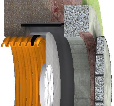
8 0 T 0-: T T T T T T T W T T T () ( ') < m 000 / (0) 0 (0) TW m & m 000 / election and pecification. ll acceptable options (ie:, plastic, concrete) which are suitable shall be specified for in the design template.. ach shall be specified in accordance with the schedule (standard W--00).. lan view designs shall be provided in the design in accordance with standard W--0.. ef column Table 0-. Wall thickness to be 0 if concrete is not reinforced. Wall thickness to be > than the larger quoted thickness if reinforced concrete (value in brackets). This is to ensure clear cover can be achieved.. refabricated s may be subject to depth limitations. efer to products portal for all limitations of use.. ituations of use of s are described in W--.. ll quoted depths are to outflow pipe invert. 0 (0) 0 (0) T 0-: T TT T T W X T T T a c 000 / m m m.m.m.m mm/ m T mm/ m T 0 mm/ m T mm/ m T 0 mm/ m T mm/ m T 0 oncrete einforcement (if required):. s shall be concrete cast in situ with shaft reinforcement only where the Water gency advises that the is subject to surcharge conditions. therwise, reinforcement is not required.. einforcement shall be specified in the schedule of the design template (refer standard W--00) and as per Table einforcement shall be placed as per standard W--0 (ie: horizontal hoops at 00 spacing, vertical bars at spacing).. Undertake specialized structural design for s deeper than m or s greater than 00 in diameter to determine what reinforcement (if any) is required. T egarding Table 0-: ouyancy ontrol a. lotation mitigation shall be provided when the depth to invert of the outflow pipe exceeds the value specified in column of Table 0-. b. lotation shall be mitigated by extending the base diameter. c. or every meter in depth below the depth limit, increase the base diameter by the value given in Table 0-. d. s, s and prefabricated s do not require flotation mitigation unless the manufacturer's installation instructions or the product web portal specifies it. ouyancy ontrol xamples xample a: m deep00 diameter requires no flotation mitigation. xample b: m deep 00 diameter requires a x 0 = 0 addition to the base diameter. xample c:.m deep 00 diameter requires no flotation mitigation. xample d:.m deep 00 diameter requires a x 0 = 0 addition to the base diameter. U 0-: T V UTW VT T T TT W UTW VT (T ) W VT X : W, UTW. UT T V Y T. T (0) XU Z (ie: ( - ) V X U UTT 0)- UTW VT UTW VT UTW VT UTW VT U VT T X : T W. X T (0) & T T T T X : W & UTW. UT T V T < T W X : X, XT T T 0. W UT T V T > 0 W VT W VT X : X, XT UTW T U W WT T (0)- T VT T U T VT- VT T egarding igure 0-. Where possible, projected obvert levels of inflow and outflow pipes to match (to restrict flooding of upstream pipes). rop through chase shall be < 0 + (outflow Ø - inflow Ø). g: (from eg ): 0 drop. 0-(-) = 0. rop. Where outflow sewers <, provide adequate fall through the chase: in 0 change in invert for bends < 0 & straight through. in 0 change in invert for bends > 0. Where outflow sewer >, maintain lowest connecting sewer grade through the chase. VT W VT 0 T 0-: T TY V W < >0 (W) TY UT T WT V W T WT W W-- WT Y >0 (WW TT T TW WT Y. or ) T XT W--. T egarding Table 0-: drops are required where the difference in invert level between the incoming and outgoing sewer mains is greater than the minimum height of a drop (refer Table 0-). Where the required drop is less than the minimum, evenly grade the sewer back to the nearest upstream maintenance structure. f this leads to the maximum grade being exceeded or the line has already been constructed, contact the Water gency for advice. T 0-: T, T & T (m) YT YT W VTX Z () Z () (m) + + U + U to 0 0 to 0 > to.. to. > to to >. to.. to. > to to. T - to 0. to to to >0 > > > 0. to > 0 0. to > >0 UT WT Y V T egarding Table 0-. Whether a system is open or closed shall be determined in accordance with W--0.. or an example of a plain drop with bottom bend, refer W-- & igure -.. or an example of a plunge pool, refer igure - &. lunge pools may also be designed with internal drops. ontact the Water gency for advice on any such structure.. ontact the Water gency for requirements of vortex drops.. lunge pool depth = min + (drop height - min drop required for plunge pool) x rate of depth increase. eg: m drop of an open incoming 0 sewer = 0 + ((-.) x 0) =. or drops to bends (rather than to plunge pools), care must be taken to avoid high velocity sewage jumping out of the chase and over the table. This risk is diminished where:.. ends direct sewage to the outlet... The drop flow has a minor change in direction within the... The drop flow intersects a relatively large flow.. lunge pool depth shall be from the W of the outflow sewer. T 0-: T T W (< T) U ( T T) T YU ( X & T Y), or U XY V VY T ( T). UT WT Y W T U T UT. ost comparison between internal and external drop can be based on the difference in concrete volume between the two different drop types which depends largely on the depth and diameter of the two different types. The water agency will decide the optimum type based on cost and operational risk factors. to 0 to to to to T - VTX + U >0 > > > > > > > > > = U T (> T) T TU TT T T / T T egarding Table 0-: The Water gency will indicate the risk level to be applied to concrete s. ydrogen sulphide risk assessments may be calculated in accordance with W--0. atural ventilation shall be implemented as per drawings W--0 & 0. oatings and linings shall be prepared, applied and tested as per the W 0- election and pplication of rotective oatings anual. alcium luminate cement mortar, whilst an effective rehabilitation system, is not suitable on new concrete surfaces (which are too smooth). + 0mm / m + 0mm / m 0 + 0mm / m 0 + 0mm / m mm / m 0 + 0mm / m 0 + 0mm / m mm / m TT WT Y mm U TT TW U T U 0/0/ / T / / V -U T T 0/0/ / T / / T V : W: : WW W.... X. W T T: T: V: WW W U 0 V. UT. T UY 0 UY 0. 'V T U T WT W W T T UT T T W--0 lanning esign onstruction 0
9 0 etailed aintenance ole esigns equired When: The designer is required to produce a scale plan view drawing for concrete s with the following:. iameter >00, or. or more incoming sewers, or. or more drops, or. drop >, or. ewer intersection offset from centre, or. landing, or T 0-: T T VW UT: UT UT UT T T T ( : T Z) U TWY VT W Y VT WT m T V T & UT T T T T T T UT T W-- W-- T T T, Z W Y WT UT U T T + x W T T W U, XT T T UTT TT VT TT W U. T VT V T VT & T T X 0 T T T T U Y, X 0 T W W T U Y T / T V X 00 V T U T T T > m ( or WW) >m (W) T T T U W VT V TY W >.m V T V TT. T W-- W T (XT) T TT XT T UT TY TT V T T T TT W VT T ' W T T T TT T W T W W TV T UTW W U TT T T T T T T T T TT. T T TT (V T ' T) V UT ( W) T U. > W W T > W UT ( ) TT X UT XT T TT XT T TY T. Y T T T XT ' U T Z XT T T T T U XT T T egarding Table 0- items: tem. Where practicable, ensure that neck of lies either completely inside or completely outside of a paved surface. aintain min 00 clearance between outline of neck and any pavement edge. ocate ladder / step irons where neck and shaft internal diameters intersect. tem. efer Table 0- for details. tem. ne standing area shall be directly in front of the ladder / step irons. tem. Where possible, ladder shall be located to allow standing plank access to all high level sewers. standing plank spans a ladder's rung to a step iron on the other side of shaft. efer mrwa-s-. tem. ominate level & position. efer standard W-- for details. tem. ocate 00 below centre line of high level entry into shaft. tanding plank position shall be indicated. 0 wide. ot a permanent fixture. rought on site as required. pans from a ladder / step iron rung to a step iron on the other side of the.. ew connections are being made to an existing. n the case of, the scale plan shall show existing details and the proposed modifications necessary to ensure structural integrity while achieving the requirements outlined below. xisting s should be inspected as part of the design process to ensure that they are suitable for connection. tem. ocate opposite and at the same level as a ladder / step iron rung. tem T. ax anglular deflection within a chase is 0. aximum angle of incidence of a high level sewer to the shaft wall shall be from perpendicular. ny greater angular deflection shall be accommodated using a bend external to the. tem V. uter radius shall be inner radius + inflow pipe. ll curves shall be tangential to both the inflow and outflow sewers. Tangent curves shall be contained within the inner shaft circumference. ngular deflection of a chase is limited to 0. xternal bends are preferred to increasing a 's size to provide for more angular deflection within the. tem W. referred that a chase from a drop pipe be at > to the outflow. tem X. tem Y. : T T T T W TT xternal bends shall be as per W--0. learance equal to the diameter of the drop pipe is required from a drop pipe to any ladder, other drop pipe or other fixture. = W (ie: ) : T T T T =00 T UT T >000 = W =.0 > T T =00 U 0-: X. WT T XTT TT T UT T >000 =.0 T UT T >00 0 =.00 =.00 =.0 0 > =. 0 =.00 =.0 0 = =.0 T >00 T T =00 =.0 XTT. V =. : T T XTU T U 0-: X. WT U T 0 0 XTT TT U 0-: X. WT XT XT T TT Y W T + T 0 0 U T T W =.0 XT + =.0 : T T : T T XTT TT 00 T V = ~. XTU T. >00 > XTU T. T V = ~. & ~0. mm U TT TW U T U 0/0/ / T / / V -U T T 0/0/ / T / / T V : W: : WW W.... X. W T T: T: V: WW W U 0 V. UT. T UY 0 UY 0. 'V T U T WT W W T T T T T T W--0 lanning esign onstruction 0
 specified in Table 0- is the minimum.")
 to < 00 thick,.. imiting the temperature of the concrete to < c,.")
10 0 T. TUT. : W-- T T : W-- & W-- : : W-- T oncrete:. ll concrete shall be unless stated otherwise.. concrete shall be normal class as per W.. 0 concrete shall be special class with exposure classification to W oncrete aggregate shall be < 0mm.. The wall thickness(s) specified in Table 0- is the minimum.. Where required, slump testing shall be undertaken by the Water gency as per 0. lump shall be 0 to 0mm.. oncrete cure heat shall be controlled to prevent early age shrinkage cracks. This shall be done by:.. imiting the thickness of concrete (at base etc) to < 00 thick,.. imiting the temperature of the concrete to < c,.. ontrol the risk of early age cracking for concrete sections > thick by:... urchasing a low heat mix from the concrete supplier, &... Use water curing to ensure a humid atmosphere and avoid drying of concrete, &... cheduling thick additions of concrete for early in the morning... n addition, control the risk of early age cracking for concrete sections > thick by:... onitoring the temperature of a placement of each configuration of thick concrete and confirming the temperature rise is acceptable, &... Using chilled water / aggregate where temperature will likely be excessive. oncrete lacement:. oncrete ormwork to 0.. ll concrete shall be placed within 0 minutes of being mixed. 0. nce mixed, additional water shall not be added.. oncrete shall not free drop >.m.. alling concrete shall not contact reinforcement (this is required to prevent segregation).. xposed concrete shall be kept wet (ie: cover in plastic / wet hessian) for > days.. xternal formwork not required (unless specified otherwise) but wall & base concrete thickness shall not exceed 00.. oncrete must be free of voids. vibration probe shall be inserted to 00 below the underlying layer surface at intervals < or of zone of influence of the probe, whichever is less. ess than 00 high of concrete shall be added between vibration events. oncrete ost lacement:. nternal finish to class finish (0).. ackfill only after 0% of nominal concrete strength achieved (ie: min hours).. ormwork may be removed after hours provided structure is not loaded until 0% nominal concrete strength achieved.. oncrete shall be rejected if it is: porous, segregated, honeycombed, or contains surface defects / cracks > 0.mm... epair defects < mm with low viscosity epoxy... epair defects > mm with epoxy mortar. 0. day drying shrinkage cracks shall not exceed 00 microstrains. teel einforcement:. einforcement shall be as per /Z :.. hape,.. trength grade 00a,.. uctility class.. end, cut, splice and fix reinforcement steel as per 00.. ll reinforcement shall have > clear cover.. ll reinforcement mesh shall be unless stated otherwise. ottom reinforcement layer shall be > from slab bottom. eparate reinforcement layers using high reinforcement spacers / chairs.. haft reinforcement bar size as per the design schedule.. haft horizontal hoops (rings) to be placed centrally at 00 separation.. haft vertical bars to be placed centrally at separation.. oop, bar and mesh to overlap as follows:.. mesh- 00 overlap,.. bar- 00 overlap,.. bar- 00 overlap, and.. 0 bar- 0 overlap... verlap and fix reinforcement bars of base to vertical bars in shaft. W--0 U 0-: T T T egarding references:. recast concrete s require water agency approval.. ifferent shaft materials shall not be used, ie: the same material shall be used between base and top of shaft.. Where specified as acceptable in the design, prefabricated s (eg: plastic or s) may be used provided:.. The assembly is lisetd as acceptable in the products portal... n entire integrated assembly from base to surface is being used... The manufacturer's installation arrangements are followed.. Where no suitable products are listed by the water agency, cast in situ concrete s shall be constructed. WT T ( U) U U T T UY TT T T. T T TT T T ( V / ) V / ( ) U 0-: T TUT T T T W UT Y U T egarding oncrete onstruction oints:. aximum height between construction joints shall be 00.. Water stops to be placed centrally around perimeter of construction joints when:.. The joint is deeper than m, or.. Where geotechnical information indicates that the construction joint is below the water table, or.. round conditions during construction indicate that the construction joint is below the water table... Waterstops shall have an overlap of 00.. astic construction joints may only be used between shafts and flat tops (refer igure -).. oncrete construction joints shall be constructed in the following way:.. ower section shall cure for min hours before next pour commences... Within hours of the next pour,... cabble the upper surface to expose aggregate, removing > deep of material, or... etard the cure in the top of the lower pour (using chemical treatment, eg: preco-h) when placed and then high pressure water clean off soft surface within hours of the next pour... emove all debris from surface with a stiff brush or compressed air (if scabbled)... Within hours of the next pour, wet the surface (without ponding water).. pply concrete bonding agent or cement slurry (cement : sand. <0 thick) to the surface... our next section to a maximum height of 00 (if practicable)... nstall water stop centrally around top of placement while wet in accordance with the manufacturer's requirements (if required)... Wire restrain water stop to reinforcement (if present) to hold in the vertical position. mm U TT TW U T U 0/0/ / T / / V -U T T 0/0/ / T / / T V : W: : WW W.... X. W T T: T: V: WW W U 0 V. UT. T UY 0 UY 0. 'V T U T WT W W T T TUT UT T T W--0 lanning esign onstruction 0

 0 0 0 0 0 X = W TU 00 00 00 00 00 00 00 00 00 0 0 0 T (T ) - 00-00 - 00-00 - 00 0-00 0-00 x (0-00) * Z = T 0 0 0 00 0 0 0 0 0 0 U 0 T 00 T egarding")

 T 0-: T T T UT ( W) T T T UT T W W > T T T T / T T T T T T TV U > 00ka T T 0- U 0- T UT V T T 0- T W UT YTY UT T T. 0 U > Ø T WT T 0-.")


 nverted \"U\" shaped dowels with both ends inserted into the base concrete is an acceptable alternative to straight bar.")
11 0 eneral otes: oncrete and reinforcement as per drawing W--0. or s containing an internal drop, refer to drawing W-- for TY XTT T additional requirements. or s containing an external drop, refer to drawing W-- for U XTT T additional requirements. >Y ( T 0-) T 0-: T T T T VT Z <m TW 00 m& 00 m W W Z (T ) X = W TU T (T ) x (0-00) * Z = T U 0 T 00 T egarding Table 0- * Two layers of reinforcement required in this case. Where base reinforcement is to consist of bars, orientate one set of bars in one direction at 00 spacing and one set of bars at 0 to this direction also at 00 spacing. ases at a depth > m require 0 concrete. U 0-: TY (T VW) T 0-: T T T UT ( W) T T T UT T W W > T T T T / T T T T T T TV U > 00ka T T 0- U 0- T UT V T T 0- T W UT YTY UT T T. 0 U > Ø T WT T 0-. T WT T X ( T 0-) >Y ( T 0-) tem. tem. tem. tem. tem. base shall not be laid onto compacted materials. Where over excavation occurs, for s > m deep and for s >Ø00, place base onto > 0 of blinding concrete, poured immediately after excavation. Use 0 concrete to construct bases which have external drops or are > m deep. ast base, nib wall and pipe connector supports in one piece. ut out any part of pipe connectors which protrude within inner diameter of the. >Z ( repare top of nib wall surface in accordance with igure 0-. T o not insert dowels within 00 of horizontal alignment of pipe. nsert to depth X as per Table ) nverted "U" shaped dowels with both ends inserted into the base concrete is an acceptable alternative to straight bar. alf as many bars would be required in such cases. Z () 0 0 / > 00 U 0-: TY (T VW) U Y U 0 U T T 0 U U T T T T T T UT UT ~ U 0-: V T (T VW) U 0-: T (T VW) T T. T UT. T > x Ø. T UT.. T: UY 0. W: : T: UY 0 : mm U TT TW T V: WW. WW U T U 0/0/ / T / / W. X W -U T 0/0/ / T / /. W V T T V U 0 U Y U T Y U T T to x Ø T U Y U T T T Y T U UT : efer Table U 0-: T (T VW) T UT. U T WT U 0-: T (T VW) T T. T to x Ø. T T W W T T T T TUT. UT. 'V. T W--0 lanning esign onstruction V 0 U 0 U U (W ) UT T 0-: T T T >00 T Ø U 0-: TY ( VW) T >Y ( T 0-) > X ( T 0-) T T egarding Table 0- tems: Ø 0
 Ø/ U -: T > W 00 T T T UT T T T / / T V / / ( ) T / / V WV (&) V WV (&) U + V WV (&) UT T T TT T T V WV TT XY T T T ( ') V / () W V WV / / T T / / / T / /.")


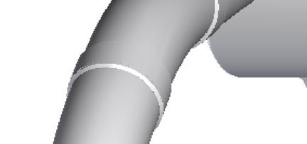
12 0 UT UT V T > T TT T 0 WT U UT UT UT T TT T Ø XY T T ( T.) Ø/ U -: T > W 00 T T T UT T T T / / T V / / ( ) T / / V WV (&) V WV (&) U + V WV (&) UT T T TT T T V WV TT XY T T T ( ') V / () W V WV / / T T / / / T / /.. T V T T / T V T U T T W--0 T T, W--0 U 0- T 0- TT T T UTT W 0 T VTY. Z T - U + 0, TY T U - UT T U 0- T 0- U T V XY T T ( T.) W--0 W-- U T UT T & U Y T T W T U -: T T V W WT W. T: UY 0. W: : T: UY 0 : mm U TT TW T V: WW. WW U T U 0/0/ / T / / W. X W -U T 0/0/ / T / /. W T T V U 0 U T WT UT T U W X T VU T T - T TY. XY T T ( T.) T -: T W T TT TT Ø/ TT T Z T inimum drop represents the minimum difference between the of the incoming sewer and outgoing sewer that can be achieved using conventional fittings.. T T T T TUT 0 T T W W T W--. UT. 'V U -: T T W T V U U ll < components shall be V WV, not cemented in place. ll components shall be V WV. ll components shall be or V WV. ll > components shall be. re-fabricated s may have internal drop options. nstall as per products portal conditions. tem. hase for drop pipe shall be straight if the base is concrete. urved or base chases are acceptable locations to receive drop pipes. lug the entry point of any prefabricated chase used to receive dropped flows. tem. poxy or cement mortar behind bend if concrete base. o not enclose bend so that it cannot be easily replaced. f or base, ensure drop pipe is vertical and drops the high level flow directly into a prefabricated chase. nstall bottom of bend above the chase by drop pipe Ø /. ngle drop bend so that it is in line with the direction of the chase at that position. tem. efer igure -, &. Where grade of incoming high level sewer is > in 0, refer to igure -. tem. ne support bracket per 00 rise. nly one required below top bend if < 00 drop. nstall directly under a socket if possible (provided the bracket hole is 00 clear of any other penetrations) so that the bracket can support the vertical weight of the pipework. tem. Wall penetration to be between 0 and 00 larger in diameter than the outside Ø of the connecting pipe. mooth cut penetration is not acceptable. tem. it end of socket flush with inside wall of. tem. step iron is to be placed directly across the from a ladder rung at ~.m height below the center of the high level sewer. ot required for drops <.m. rill holes in set concrete and install step iron using epoxy as per the manufacturer's specification. T T T egarding Table - items: U -: T 00-0 W W UTU UT UT W ("U") T -: T (V WV ittings escribed) V 00 0 T U -: T T ( VW) lanning esign onstruction
 TYY T XY T TY UT / T, XY T T 0,.. V T U >r T W W--0 W W--0 U 0 to U > Ø.")


13 0 T -: T (in pproximate rder of onstruction) T T UT UTW T 0 U TUT T T / T V VW U V U T W T T T T T T 0 T TYY TY UT / T TY UT / T T T 0 () TYY T XY T TY UT / T, XY T T 0,.. V T U >r T W W--0 W W--0 U 0 to U > Ø. U - U - W W--0 T W W--0 T U Ø T 0- U 0 to UT T U W0 U T U 0- T T T T W U - W W-- T U T UT T U 0 r 0 U = = U / W 0 r r ~ > T T egarding Table - tems: tem. ender cut out surface to the required finished dimensions, ensuring that the surface is smooth and free of surface defects. select and apply render as per W0. tem. repare entire surface where drop pipe encasement will contact the shaft external wall. xternal drops not permitted by W. The dimensions and encasement reinforcement provided are suitable for high level sewers <. or high level sewers >0, a specific structural design shall be undertaken. r tem. ntire base (below walls & drop pipe encasement) to be cast as a tem. owels to be inserted in pairs, one on both sides of the drop pipe as indicated in igure -. single block. nsert at 00 height intervals (between base and top of teel reinforcing mesh to extend to from perimeter of entire encasement). base. xtend to from perimeter of drop pipe concrete encasement Where base under the drop pipe is of a lower profile, bend mesh and to from shaft inner wall. as indicated. rill Ø holes into the shaft wall concrete when >0% concrete lternatively, construct base to the same depth (ie: so that thicker strength achieved. than minimum under shaft). ir pressure clean holes and epoxy bars into shaft wall. tem. atch obvert of outflow pipe with soffit of plunge pool chamber, tem. step iron is to be placed directly across the from a ladder allowing for minimum drop through. rung at ~.m height below the center of the high level sewer. tem. upport connector with concrete encasement to min Ø/ around not required for drops <.m. the connector. rill holes in set concrete and install step iron using epoxy as per tem. ut out of wall for high level overflow to be no more than 0 larger the manufacturer's specification. than the required dimensions. tem. nstall as per W0- selection and application of protective haft penetration(s) required for ventilation system integration to coatings manual. be constructed in the same manner. = T W T r= U > 00 W UTW W > r 0 V >r W UT W T UT U W + U W >r T 0- U -: TUTU (T VW) T W TY T = U / W. r = U. > >r U -: XT T WT U W. T: UY 0. W: : T: UY 0 : mm U TT TW T V: WW. WW U T U 0/0/ / T / / W. X W -U T 0/0/ / T / /. W V T T V U 0 U -: WT T (T VW) U -: TUTU ( VW) U T WT W--. UT. 'V. T T T XT TUT V T T W W T T 0 lanning esign onstruction


: 00 T T T T VT TT VT / T V T 0.")


 to 0 T > > > UTY T 0 W T T T W U T T T UTY U T T () T W T V UT T x x 00 T VT T TU V V UT T / XY / V etc the vent pipe Ø.")

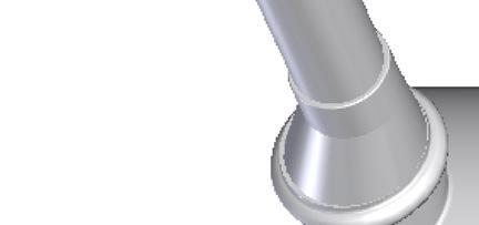
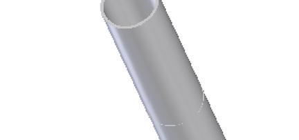
14 T -: T TUTU V UT TY TUT U V V WY,, / T * U UT VWY, V, U T * V UT T U T * TT, T VWY T * U TU T ( V) Y V UV VT TY Y 0 V 00Ø T W >00 0 x 0 U T T s WT > 0 & UT WT T TUTU UT-T / UU * oncrete infill covers may not always be available for s. Where none of the suppliers have concrete infill covers available, solid top covers may be used. TUT <00 Ø (WT T U) > 00 Ø U T VT T T W > 00 T T W /W 00 & 00 T T W< 00 T T T X T T WT T T T T T T TT T WT Y V 00 rease all metallic mating surfaces. Where the cover level is above the /, grade the surrounding surface level at in to the edge of frame. nsure area around cover is free draining to ensure water does not pond over the cover. olt down covers shall be installed in accordance with the code. covers may utilise any approved cover at any location. aximum slope of in in non-trafficable areas. aximum slope of in 0 in trafficable areas. T -: T T (n pproximate rder of onstruction): 00 T T T T VT TT VT / T V T T T T T T W--0 T U T T T TT U T TT UT T T TYY V WV U 0- T 0- V UT T WT T. T TY, W-- T - / / XY / V etc U. W W--0 T < 00 T U T described in this section. tem. nner and outer formwork required. o construction joints in the cone or neck allowed. Thickness as per shaft. tem. our the neck to finished surface level with frame tem. held in the correct location within the concrete. eck thickness same as shaft. Top surface shall be flat to class finish (0). ngle to match the finished top surface. tem. Vent penetrations should occur in a vertical section tem. of the cone wall, behind the ladder, >00 away from ladder wall brackets. enetration shall be between 0 and 00 larger than U -: T (on Trafficable rrangement with Vent escribed) X / T T T W TT U -: T T T T ( VW) T -: T T T WY ( VT) T WY T / T T T / = U Y T T ( T -) to 0 T > > > UTY T 0 W T T T W U T T T UTY U T T () T W T V UT T x x 00 T VT T TU V V UT T / XY / V etc the vent pipe Ø. mooth cut penetration is not acceptable. Vent pipe requires continual grade to the manhole so that it drains. eal gap between vent pipe & penetration with epoxy or cement mortar, ensuring there are no gaps or voids. et top of frame as per Table -. rames in non trafficable areas to have a maximum slope of in. atter back the surrounding ground where necessary to achieve a greater slope. tep irons, ladder rungs or stiles shall not protrude into the neck (applies to both conical and flat top s).. T: UY 0. W: : T: UY 0 : mm U TT TW T V: WW. WW U T U 0/0/ / T / / W. X W -U T 0/0/ / T / /. W V T T V U 0 00 to 0 (Ø00 V) 00 to 00 (0 x 0 V) T, T - U -: T T (Trafficable rrangement escribed): ove slab into position when concrete has achieved > 0% strength (ie: days). olt down if known to surcharge. tem. oop shall overlap mesh / bars as much as possible. ix to mesh / bars at all intersections. tem. nstall as per manufacturers requirements in consideration of top slab weight. U T WT tem. ocate centrally. nsert 0 and protrude min 00. tem. Where shaft reinforced, reinforce neck with -0 reinforcing hoops (Ø00 if Ø00 cover, Ø00 if 0 x 0 cover). verlap 00. tem. et top of frame flush with the top of the paved surface. T T W W T T T T T TUT. UT. 'V. T W-- lanning esign onstruction V T W--0 T. U T ZT T U T 00% UTY Y. U - U T T T U (T / T) Y U - T - U - T - T TY T T T 0, 0, 0 & 0 T T T W WT T 0, 0, 0 & 0. UT W U. > 0 T T. T TY T T U - & TUT Y T. VT T T T T T - U. T V / ( T T egarding Table - items: oncrete and reinforcement as per W--0. U) W nlet sewers shall not connect into shaft within 00 of top slab. tem. rior to mastic placement, prime surfaces of shaft and flat top as recommended by the mastic supplier. U -: T TUT T tem. Use inner and outer formwork. T T 0 0 T T T T 00 (if 00Ø cover) or 0 (if 0 x 0 cover) T -: T (n pproximate rder of onstruction): T T Ø00 () 00Ø V Ø00 () 0 x 0 V X T TT T T egarding Table - tems: oncrete as per drawing W--0. nlet sewers shall not connect into the conical part of. ote that vents may also connect to flat top s as tem. Ø00 00Ø V Ø0 0 x 0 V >0 >0 (Ø000 ) >0 (Ø00 ) >Ø00 00Ø V >Ø00 0 x 0 V T -: T TUT TY T egarding overs: deg 0
15 TW 0 T TW 0 0 T T T or x X > 00 T T, UT & W T >00 T UTU TUT 00 to U - (T VW). TT U / T T TU T < 00 TT T W U - TT T U - nstallation otes:. adders, step irons and landings to be constructed of (or better) ( & finish class ), or plastic encapsulated steel (..). adders shall:.. or mass produced prefabricated ladders, comply with the manufacturers instructions. f there is insufficient instruction, comply with the requirements described in this drawing... etractable stanchions not required unless there is electrical or mechanical equipment inside the... ot be built with cages... ave rungs spaced between 0 and apart... onsist of a continuous vertical run from top to bottom with no overhangs or offsets... e fastened at the top, base (table) and at intervals <.m as per igures -, &... e no closer to the wall than e clear of the neck & a max of 00 from. WT U U T T W x 0 T T T V T U Ø=0 U U XT T W U - (T VW) V U T ~ or x X T, UT & W T U - (T VW). T ( or ) x (00 to 0) T T. tep irons shall be:.. nly used in maintenance holes < m deep... nly used with cast in situ maintenance holes... ast into the wall where practicable... ligned vertically... qui-spaced ( + - )... lear of the neck... aximum of 00 from top surface level.. andings shall be:.. nly installed for maintenance holes > m deep (WW / ) or > m deep (W)... qui-spaced between table and surface... nstalled >m above the table... equire if > m deep to table... nstalled to facilitate maintenance of high level entry sewers if practical. "depth" is height from table to surface. or x X T, UT & W T TW 00 0 T U - or U - ( T VW). U - ( VW). T W T T T egarding racket nstallation: a. or mass produced prefabricated ladders, use only the brackets provided or recommended by the manufacturer. b. or ladders, brackets are to be located midway between rungs. c. rackets may fold outwards rather than inwards. T ( or ) x (00 to 0) X TU T U - (T VW) X T TU U Ø=0 T T., x 0 T T TW T WT W TUTU UT 0±0 T W 0 or x X T, UT & W T T e igures - & :. nstall fasteners min clear of any construction joint.. nstall as per manufacturers instructions.. tep : drill hole to required depth and diameter (as per manufacturers instruction).. tep : clean out hole (using air pressure). or igure -:. tep : insert adhesive capsule.. tep : insert threaded rod and spin.. tep : wait for adhesive to set (nominally 0 mins).. tep : tension nut. or igure -:. nsert compression bolt.. Tension nut. Ø = WT + U -: T UT T < T XY T U. T 0. W T., x 0 T T T U - or T egarding rop ipe upports: a. ocate clamps immediately below sockets where practical. b. inimum one clamp required per pipe length / pipe fitting at a maximum spacing of 00 c. ll brackets, clamps and fasteners shall be constructed from to finish.. lamps and brackets to be constructed of min 0 x flat bar. d. or supports for drop pipes >, refer W drawing : TW 00 0 T TW 00 0 T T TU T U - (T VW). T TT T egarding andings: nly approved pre-fabricated landings may be used. ll maintenance holes requiring landings shall be > - 00Ø. nstall step iron, vertically aligned, adjacent to the ladder, 000 above the landing. andings shall not impede upon the ladder climbing space allowance. upport structure to be welded to finish. rackets may be packed up to 0mm where fitted to the wall. anding to be wide and a snug fit to the concrete wall. Where a landing can be located to enable work to be performed on a high level entry sewer, it shall be located 00 down from the centre line of the sewer. n such cases the landing shall be wide. 0 x 0 x V 00Ø W / U - ( VW). YUT T ( ) - T egarding tep rons: ast step irons into concrete if practicable. therwise install as per the manufacturer's instruction, nominally ensuring: rill Ø holes at the required width. emove dust using air pressure. pply epoxy liberally to drilled holes. ammer in step irons at the corners (ie: not centre of rung). o not use until epoxy has cured. 000 T T U - or T 0 x 0 x V U - (T VW). TUTU mm U TT TW U T U 0/0/ / T / / V -U T T 0/0/ / T / / T V : W: : WW W.... X. W T T: T: V: WW W U 0 V. UT. T UY 0 UY 0. 'V T U T WT W W T T Y TUTU TT T T W-- lanning esign onstruction 0
SHORT WAY SYMMETRY/SYMMETRICAL SYNTHETIC TREAD TELEVISION VERTICAL VITREOUS VOLUME. 1 BID SET No. Revisions / Submissions Date CAR
 //0 :: T U 0 : /" = '-0" 0 0 0 View ame T W T U T UT 0 0 T T U 0 U T T TT TY V TT TY T. 00' - 0" T U T T U T T U U ( ) '-" T V V U T W T T U V T U U ( ) T T 0 T U XT W T WW Y TT T U U ( ) U WW00 T U W
Column w/laterals. Steel Column A992 50ksi Steel (see sheets 4-7)
") olumn w/ SOREOR HEIGHT WITH ddtional display area consisting signs, arches, message centers or video above or below the scoreboard. (see sheets -6) for column and pier sizing) TOP SOREOR SETION Overall
olumn w/ SOREOR HEIGHT WITH ddtional display area consisting signs, arches, message centers or video above or below the scoreboard. (see sheets -6) for column and pier sizing) TOP SOREOR SETION Overall
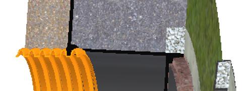
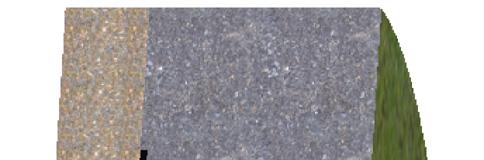
Coarse Sediment Traps
 Coarse Sediment Traps SEDIMENT CONTROL TECHNIQUE Type 1 System Sheet Flow Sandy Soils Type 2 System [1] Concentrated Flow Clayey Soils [2] Type 3 System Supplementary Trap Dispersive Soils [1] Though primarily
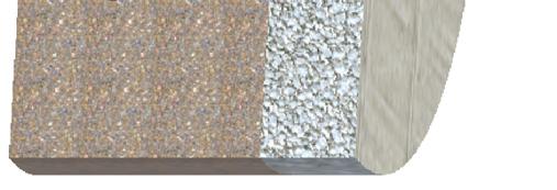
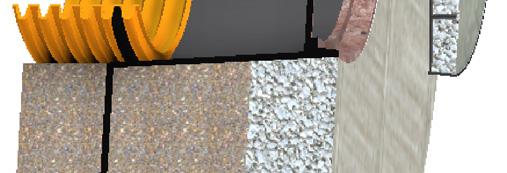
U-Shaped Sediment Traps
 U-Shaped Sediment Traps SEDIMENT CONTROL TECHNIQUE Type 1 System Sheet Flow Sandy Soils Type 2 System Concentrated Flow Clayey Soils [1] Type 3 System Supplementary Trap Dispersive Soils [1] Generally
Project PAJ2 Dynamic Performance of Adhesively Bonded Joints. Report No. 3 August Proposed Draft for the Revision of ISO
 NPL Report CMMT(A)81 Project PAJ2 Dynamic Performance of Adhesively Bonded Joints Report No. 3 August 1997 Proposed Draft for the Revision of ISO 11003-2 Adhesives - Determination of Shear Behaviour of
Section 8 Column radiators
 Section s Description Connections Standard without built-in valve -or- Version with built-in valve Air vent, Drain Fixing and mounting Pressure versions, Fittings, Surface finishes, Special versions eat
Series 3000 and XE-Series Engineering Data
 Series 3000 and XE-Series Engineering Data A C A U S T R A L I A Series 3000 and XE-Series Engineering Data The NEW era of Series 3000 and XE-Series Cooling Towers continue to exceed the industry standard
Odor Removal Filter. Model Note) 1 8, , , , 3 4. Model/Free Standing Type AMF800. Model/Piping Support Type AMF Port size
 1 8, , , , 3 4. Model/Free Standing Type AMF800. Model/Piping Support Type AMF Port size") dor emoval ilter Series os fficiently can remove odor in compressed air with an activated carbon element. The unit is designed for use in the area such as a clean room where odors must be avoided. Can
dor emoval ilter Series os fficiently can remove odor in compressed air with an activated carbon element. The unit is designed for use in the area such as a clean room where odors must be avoided. Can
ENVIRONMENTAL EFFECTS OF EARLY AGE AND LONG TERM RESPONSE OF PCC PAVEMENT
 ENVIRONMENTAL EFFECTS OF EARLY AGE AND LONG TERM RESPONSE OF PCC PAVEMENT Luis Julian Bendana, Engineering Res Specialist I New York State DOT Jason Wise, Graduate Student Ohio University ABSTRACT Early
Construction Exits Rock pads
 Construction Exits Rock pads SEDIMENT CONTROL TECHNIQUE Type 1 System Sheet Flow Sandy Soils Type 2 System Concentrated Flow [1] Clayey Soils Type 3 System Supplementary Trap Dispersive Soils [1] Minor
Materials. Use materials meeting the following.
 208.01 Section 208. SOIL EROSION AND SEDIMENTATION CONTROL 208.01 Description. Install and maintain erosion and sedimentation controls to minimize soil erosion and to control sedimentation from affecting
Construction Exits Vibration grids
 Construction Exits Vibration grids SEDIMENT CONTROL TECHNIQUE Type 1 System Sheet Flow Sandy Soils Type 2 System Concentrated Flow Clayey Soils [1] Type 3 System Supplementary Trap Dispersive Soils [1]
Assembly Instructions for the 1-Wire Weather Station V2.0/V3.0
 Assembly Instructions for the 1-Wire Weather Station V2.0/V3.0 Tools and Supplies Required (not included): Phillips screwdriver 3/8" wrench Drill with 5/32" bit "U" type mounting bracket (i.e., part number
Introduction...COMB-2 Design Considerations and Examples...COMB-3
 SECTION DIRECTORY General Information Introduction...COMB-2 Design Considerations and Examples...COMB-3 Combination Assembly Recommendations and Limitations Composite Configurations...COMB-4 Typical Sealant
IBV Series C Carbon Steel Inverted Bucket Vertical Steam Trap
 Local regulations may restrict the use of this product to below the conditions quoted. In the interests of development and improvement of the product, we reserve the right to change the specification without
IBV Series Z Alloy Steel Inverted Bucket Vertical Steam Trap
 Local regulations may restrict the use of this product to below the conditions quoted. In the interests of development and improvement of the product, we reserve the right to change the specification without
Figure 1: Representative strip. = = 3.70 m. min. per unit length of the selected strip: Own weight of slab = = 0.
 Example (8.1): Using the ACI Code approximate structural analysis, design for a warehouse, a continuous one-way solid slab supported on beams 4.0 m apart as shown in Figure 1. Assume that the beam webs
ROCK EXCAVATION (GRADING) OPSS 206 INDEX
 OPSS 206 INDEX") 206-2 - OPSS 206 INDEX 206-2.1 GENERAL 206-2.1.1 Classification of Rock Materials 206-2.1.2 Tender Items 206-2.1.3 Other Excavation Tender Items 206-2.1.4 Specifications 206-2.1.5 Special Provisions 206-2.1.6
206-2 - OPSS 206 INDEX 206-2.1 GENERAL 206-2.1.1 Classification of Rock Materials 206-2.1.2 Tender Items 206-2.1.3 Other Excavation Tender Items 206-2.1.4 Specifications 206-2.1.5 Special Provisions 206-2.1.6
flexible couplings for pipe repair
 A R P O L R E P flexible couplings for pipe repair 1 TABLE OF CONTENTS Advantages and Installation Arpol Repair Systems Nominal charts Material specifications Gaps between pipe ends Outside Diameter tolerances
The Islamic University of Gaza Department of Civil Engineering ENGC Design of Spherical Shells (Domes)
") The Islamic University of Gaza Department of Civil Engineering ENGC 6353 Design of Spherical Shells (Domes) Shell Structure A thin shell is defined as a shell with a relatively small thickness, compared
The Islamic University of Gaza Department of Civil Engineering ENGC 6353 Design of Spherical Shells (Domes) Shell Structure A thin shell is defined as a shell with a relatively small thickness, compared
S E C T I O N 1 2 P R O D U C T S E L E C T I O N G U I D E - H E L I C A L S C R E W P I L E F O U N D A T I O N S
 1. P R O D U C T S E L E C T I O N G U I D E - H E L I C A L S C R E W P I L E F O U N D A T I O N S Helical foundation pile includes a lead and extension(s). The lead section is made of a central steel
2D - STRIP ANCHOR LIFTING SYSTEM
 2D - STRIP ANCHOR LIFTING SYSTEM WWW.TERWA.COM Terwa reserves the right to make changes to the documentation at any time Page 1 OVERVIEW LIFTING CLUTCHES AND TRANSPORT ANCHOR SA-B SA-ST SA-TTU UNIVERSAL
@Copyright 2016 SKAPS Industries.
 SKAPS INDUSTRIES 571 Industrial Pkwy, Commerce, GA 30529 Phone: (706) 336 7000 Fax: (706) 336 7007 E Mail: contact@skaps.com SKAPS GEOCOMPOSITE DROP IN SPECIFICATIONS @Copyright 2016 SKAPS Industries www.skaps.com
Snow Melting Design Guide: Outdoor Stairs (Pavers)
") Snow Melting Design Guide: Outdoor Stairs (Pavers) What is Snow Melting? Have you ever seen snow fall on an already warm car? It melts instantly. This is the essential idea behind snow melting systems
Snow Melting Design Guide: Outdoor Stairs (Pavers) What is Snow Melting? Have you ever seen snow fall on an already warm car? It melts instantly. This is the essential idea behind snow melting systems
Entrance exam Master Course
 - 1 - Guidelines for completion of test: On each page, fill in your name and your application code Each question has four answers while only one answer is correct. o Marked correct answer means 4 points
Example 1 - Single Headed Anchor in Tension Away from Edges BORRADOR. Calculations and Discussion
 Example 1 - Single Headed Anchor in Tension Away from Edges Check the capacity of a single anchor, 1 in. diameter, F1554 Grade 36 headed bolt with heavy-hex head installed in the top of a foundation without
ALUMINUM STRUCTURAL PLATE HEADWALLS AASHTO LRFD BASIS OF DESIGN
 ALUMINUM STRUCTURAL PLATE EADWALLS AASTO LRFD BASIS OF DESIGN LANE ENTERPRISES, INC. www.lane-enterprises.com Required Backfill and Load Cases: ALUMINUM STRUCTURAL PLATE EADWALLS BASIS OF DESIGN Backfill
RIGID PVC CONDUIT FITTINGS AND ACCESSORIES
 AND ACCESSORIES APPLICATIONS Utilities Cable, data and communication lines Institutional, commercial, industrial buildings Residential applications, service entrances Street and highway underground feeds
Cooling Water Flow Regulator
 Temperature controlled, indirectly and directly actuated diaphragm valves / seat valves Port size G 3/8 to G DN 0 to DN 0 ontinuous regulation High accuracy No auxiliary energy required Technical data
Design Manual to BS8110
 LinkStudPSR Specialists in Punching Shear Reinforcement Design Manual to BS8110 Version 2.0 January 2018 The specialist team at LinkStudPSR Limited have created this comprehensive Design Manual, to assist
Purpose of this Guide: To thoroughly prepare students for the exact types of problems that will be on Exam 3.
 ES230 STRENGTH OF MTERILS Exam 3 Study Guide Exam 3: Wednesday, March 8 th in-class Updated 3/3/17 Purpose of this Guide: To thoroughly prepare students for the exact types of problems that will be on
Retrofit Dowel Bars In Jointed Concrete Pavement - Long Term Performance and Best Practices
 Retrofit Dowel Bars In Jointed Concrete Pavement - Long Term Performance and Best Practices Tom Burnham, P.E. Bernard Izevbekhai, P.E. Office of Materials and Road Research Minnesota Department of Transportation
Snow Melting Design Guide: Heated Walkways and Paths
 Snow Melting Design Guide: Heated Walkways and Paths What is a Snow Melting System? Have you ever seen snow fall on an already warm car? It melts instantly. This is the essential idea behind snow melting
Observational Methods and
 Observational Methods and NATM System for Observational approach to tunnel design Eurocode 7 (EC7) includes the following remarks concerning an observational method. Four requirements shall all be made
Gasketed Sewer Fittings SDR 35 Injection Molded in Sizes 4 12 Fabricated in Sizes 15 36
 Gasketed Sewer Fittings SDR Injection Molded in Sizes Fabricated in Sizes G while extra heavy support is provided under the pipe stop at branch intersections for added strength. Where available, reducing
Ferrite Cores for Induction Welding
 2005 Product Line atalog Ferrites and ssemblies for High Frequency Induction Welding Subsidiary of TT electronics plc Ferrite ores for Induction Welding F59 Typical Performance urves Ferrite Impeder Materials
8.6 Product data sheet
 Schlüter -KERDI-SHOWER Drainage floor level showers 8.6 Product data sheet Application and Function Schlüter -KERDI-SHOWER is a modular system for the construction of floor level showers with ceramic tiles.
Identification Number
 Identification Number The specification of Micro Linear Way LWL is specified by the identification number, which consists of a model code, a size, a part code, a preload symbol, a classification symbol,
ETAG 001 Edition 2012
 European Organisation for Technical Approvals Europäische Organisation für Technische Zulassungen Organisation Européenne pour l Agrément Technique ETAG 001 Edition 2012 GUIDELIE FOR EUROPEA TECHICAL APPROVAL
2244 Airport Way, Redmond, Oregon Phone Fax
 Page 1 2244 Airport Way, Redmond, Oregon 97756 Phone 541 923-2233 Fax 541 923-2255 SERVICE BULLETIN SB016-0003 Subject: Evolution Main Landing Gear Trunnion Rev B Date: 12-2-09 Pages:7 Status: Mandatory
Rock & Aggregate Drop Inlet Protection
 Rock & Aggregate Drop Inlet Protection SEDIMENT CONTROL TECHNIQUE Type 1 System Sheet Flow Sandy Soils Type 2 System [1] Concentrated Flow Clayey Soils Type 3 System Supplementary Trap Dispersive Soils
STEEL. General Information
 General Information General Information TYPICAL STRESS-STRAIN CURVE Below is a typical stress-strain curve. Each material has its own unique stress-strain curve. Tensile Properties Tensile properties indicate
B805 TEMPORARY EROSION AND SEDIMENT CONTROL MEASURES - OPSS 805
 B805 MEASURES - OPSS 805 805.1 GENERAL Construction activities frequently remove protective cover and expose soil to accelerated rates of erosion. Sediments generated thereby can be conveyed via runoff
CIVE 2700: Civil Engineering Materials Fall Lab 2: Concrete. Ayebabomo Dambo
 CIVE 2700: Civil Engineering Materials Fall 2017 Lab 2: Concrete Ayebabomo Dambo Lab Date: 7th November, 2017 CARLETON UNIVERSITY ABSTRACT Concrete is a versatile construction material used in bridges,
Rigid Pavement Stress Analysis
 Rigid Pavement Stress Analysis Dr. Antonis Michael Frederick University Notes Courtesy of Dr. Christos Drakos University of Florida Cause of Stresses in Rigid Pavements Curling Load Friction 1. Curling
Application nr. 7 (Connections) Strength of bolted connections to EN (Eurocode 3, Part 1.8)
 Strength of bolted connections to EN (Eurocode 3, Part 1.8)") Application nr. 7 (Connections) Strength of bolted connections to EN 1993-1-8 (Eurocode 3, Part 1.8) PART 1: Bolted shear connection (Category A bearing type, to EN1993-1-8) Structural element Tension
Application nr. 7 (Connections) Strength of bolted connections to EN 1993-1-8 (Eurocode 3, Part 1.8) PART 1: Bolted shear connection (Category A bearing type, to EN1993-1-8) Structural element Tension
SECTION AGGREGATE OR GRANULAR SUBBASE
 SECTION 02230 AGGREGATE OR GRANULAR SUBBASE PART 1 GENERAL 1.01 SECTION INCLUDES A. Aggregate or granular subbase as shown on the drawings. 1.02 RELATED SECTIONS A. Section 01400 Quality Requirements.
PRELIMINARY ENGINEERING REPORT FOR SANITARY SEWER COLLECTION SYSTEM OSKALOOSA, IOWA 2017
 PRELIMINARY ENGINEERING REPORT FOR SANITARY SEWER COLLECTION SYSTEM OSKALOOSA, IOWA 2017 PRELIMINARY ENGINEERING REPORT FOR SANITARY SEWER COLLECTION SYSTEM OSKALOOSA, IOWA 2017 I hereby certify that this
NNN99. Rock Engineering for the Next Very Large Underground Detector. D. Lee Petersen CNA Consulting Engineers
 NNN99 Rock Engineering for the Next Very Large Underground Detector D. Lee Petersen Overview Rock engineering 101 Cavern size & shape Construction methods Feasibility Historical projects Numerical modeling
OHD L-14 METHOD OF TEST FOR DETERMINING THE SPECIFIC GRAVITY AND UNIT WEIGHT OF COMPACTED BITUMINOUS MIXTURES
 Page 1 METHOD OF TEST FOR DETERMINING THE SPECIFIC GRAVITY AND UNIT WEIGHT OF COMPACTED BITUMINOUS MIXTURES I. SCOPE. This method of test covers the procedures for determining the bulk specific gravity
Chapter (6) Geometric Design of Shallow Foundations
 Geometric Design of Shallow Foundations") Chapter (6) Geometric Design of Shallow Foundations Introduction As we stated in Chapter 3, foundations are considered to be shallow if if [D (3 4)B]. Shallow foundations have several advantages: minimum
Chapter (6) Geometric Design of Shallow Foundations Introduction As we stated in Chapter 3, foundations are considered to be shallow if if [D (3 4)B]. Shallow foundations have several advantages: minimum
R a t i o n a l i s e d B r a k e A c t u a t o r s
 C o m m e r c i a l V e h i c l e S y s t e m s P r o d u c t C a t a l o g u e R a t i o n a l i s e d B r a k e A c t u a t o r s... for Air Disc Brake applications Disclaimer The information contained
HEAVY DUTY SWING-OUT VALVE
 ISO 900 REGISTERED COMPANY Akron Brass Company. 20 All rights reserved. No portion of this can be reproduced without the express written consent of Akron Brass Company. We will not be responsible for:
Points. Precision Positioning Table TU. Variation. Major product specifications With flange
 9 0 Precision Positioning Table Ball screw inear Points lide table with high accuracy and high rigidity in a single structure lide table Compact and slim type positioning table with an original U-shaped
Thermal Cube. Custom-built Heat Flux Sensor
 Thermal Cube Custom-built Heat Flux Sensor Specifications and Construction MR. RAZIM REFAI MR. SHAMMAWI ANDERSON DR. ANDRÉ MCDONALD Table of Contents 1. Introduction... 2 1.1 Specifications [1]... 2 1.2
Turbine Meter TRZ 03 PRODUCT INFORMATION. Reliable Measurement of Gas
 Turbine Meter TRZ 0 PRODUCT INFORMATION Reliable Measurement of Gas TURBINE METER TRZ 0 Method of operation, Construction Method of operation The TRZ 0 turbine meter is a flow meter suitable for gas measurement
TESTING of AGGREGATES for CONCRETE
 TESTING of AGGREGATES for CONCRETE The properties of the aggregates affect both the fresh and hardened properties of concrete. It is crucial to know the properties of the aggregates to be used in the making
Ceiling Diffuser. Type ADLR with circular face. Type ADLR-Q with square face 2/16/EN/8
 2/16/EN/8 Ceiling Diffuser Type ADLR with circular face Type ADLR-Q with square face TROX GmbH Telephone +49/28 45/2 02-0 Telefax +49/28 45/2 02-2 65 Heinrich-Trox-Platz e-mail trox@trox.de D-47504 Neukirchen-Vluyn
Design of a Multi-Storied RC Building
 Design of a Multi-Storied RC Building 16 14 14 3 C 1 B 1 C 2 B 2 C 3 B 3 C 4 13 B 15 (S 1 ) B 16 (S 2 ) B 17 (S 3 ) B 18 7 B 4 B 5 B 6 B 7 C 5 C 6 C 7 C 8 C 9 7 B 20 B 22 14 B 19 (S 4 ) C 10 C 11 B 23
[1] Performance of the sediment trap depends on the type of outlet structure and the settling pond surface area.
![[1] Performance of the sediment trap depends on the type of outlet structure and the settling pond surface area.](/thumbs/76/74245181.jpg "[1] Performance of the sediment trap depends on the type of outlet structure and the settling pond surface area.") Sediment Trench SEDIMENT CONTROL TECHNIQUE Type 1 System Sheet Flow Sandy Soils Type 2 System [1] Concentrated Flow Clayey Soils Type 3 System [1] Supplementary Trap Dispersive Soils [1] Performance of
Sediment Trench SEDIMENT CONTROL TECHNIQUE Type 1 System Sheet Flow Sandy Soils Type 2 System [1] Concentrated Flow Clayey Soils Type 3 System [1] Supplementary Trap Dispersive Soils [1] Performance of
--> Buy True-PDF --> Auto-delivered in 0~10 minutes. GB/T Translated English of Chinese Standard: GB/T
 Translated English of Chinese Standard: GB/T4161-2007 www.chinesestandard.net Buy True-PDF Auto-delivery. Sales@ChineseStandard.net ICS 77.040.10 NATIONAL STANDARD OF THE PEOPLE S REPUBLIC OF CHINA GB
MS/Standard how to order
 /tandard how to order I--5015 and I-5015 ype (older ontacts) 102 18 W () 1 2 5 7 8 1. onnector ype designates ilitary tandard * designates service class and with proprietary special * designates service
HEAVY DUTY SWING-OUT VALVE
 ISO 900 REGISTERED COMPANY HEAVY DUTY SWING-OUT VALVE 52 53 23 5 2 2 3 28 39 NOT USED WITH SZ HANDLE 2 NOT USED WITH SZ HANDLE 5 2 3 7 9 9 Premier Farnell Corporation. 20 All rights reserved. No portion
C-Lube Linear Way ML Linear Way L ML LWL
 -Lube Linear ay ML Linear ay L MLLL -Lube Maintenance ree Series -Lube Linear ay ML ML long term maintenance free supported! The aquamarine end plate is the symbol of maintenance free. Identification umber
Stormwater Inlet Sediment Traps
 Stormwater Inlet Sediment Traps SEDIMENT CONTROL TECHNIQUES Photo 1 Kerb inlet Photo 2 Field (drop) inlet Table 1 provides the recommended default classification of various sediment control systems suitable
NEW STANDARD SEXTANT OF THE U. S. NAVY
 NEW STANDARD SEXTANT OF THE U. S. NAVY Director of the United States of America Hydrographic Office has sent to the International Hydrographic Bureau the following data relating to the new Standard Sextant
product manual H-4204 Proving Ring Penetrometer
 05.09 product manual H-4204 Proving Ring Penetrometer nnmm Handle Proving Ring Extension Rod Coupler Penetration Rod Cone Figure #1 General Information The Proving Ring Penetrometer is a cone type of penetrometer
12.1 Product data sheet
 Schlüter -KERDI-BOARD Substrate universal structural panel, bonded waterproofing 12.1 Product data sheet Application and Function Schlüter -KERDI-BOARD is a multifunctional tile substrate for wall areas,
Positive Signal The most technologically advanced. double coated dichroic filters are used, which transmit
 The PAPI (Precision Approach Path Indicator) system is a simple and efficient, positive visual aid to the pilot on final approach. The PAPI system consists of a line of four units at 90 to the runway center
Note to reviewers: See next page for basis for the change shown on this page. L-3160 TANGENTIAL CONTACT BETWEEN FLANGES OUTSIDE THE BOLT CIRCLE
 ASME BPVC.III.A-2017 ð17þ L-3160 TANGENTIAL CONTACT BETWEEN FLANGES OUTSIDE THE BOLT CIRCLE The design procedure is based on the assumption that the flanges are in tangential contact at their outside diameter
1. Introduction. 1.1 Overview of Study:
 1. Introduction 1.1 Overview of Study: Hot and cold fluid passing through long pipes causes thermal expansion and contraction in the piping system. The fluid passing through pipes also creates fluctuations
Technical information CONCRETE / SOLID STONE. Reaction resin mortar, epoxy-acrylate-based with styrene USAGE INSTRUCTIONS
 CONCRETE / SOLID STONE USAGE 1. AREAS OF APPLICATION Heavy load-carrying attachments in solid stone, concrete, porous concrete and light concrete Suitable for attachment points close to the edge, since
Detailing. Lecture 9 16 th November Reinforced Concrete Detailing to Eurocode 2
 Detailing Lecture 9 16 th November 2017 Reinforced Concrete Detailing to Eurocode 2 EC2 Section 8 - Detailing of Reinforcement - General Rules Bar spacing, Minimum bend diameter Anchorage of reinforcement
Snow Melting Design Guide: Accessibility Ramps (Concrete and Pavers)
") Snow Melting Design Guide: Accessibility Ramps (Concrete and Pavers) What is a Snow Melting System? Have you ever seen snow fall on an already warm car? It melts instantly. This is the essential idea behind
Snow Melting Design Guide: Accessibility Ramps (Concrete and Pavers) What is a Snow Melting System? Have you ever seen snow fall on an already warm car? It melts instantly. This is the essential idea behind
Model 3024 Albedometer. User s Manual 1165 NATIONAL DRIVE SACRAMENTO, CALIFORNIA WWW. ALLWEATHERINC. COM
 Model 3024 Albedometer User s Manual 1165 NATIONAL DRIVE SACRAMENTO, CALIFORNIA 95834 WWW. ALLWEATHERINC. COM TABLE OF CONTENTS INTRODUCTION... 1 THEORY OF OPERATION... 2 General Description... 2 Accuracy...
Snow Blade Operator s/assembly Instructions
 Snow Blade Operator s/assembly Instructions TABLE OF CONTENTS Safety Messages...3 Introduction...4 Preparing for Snow Removal...4 Operating Procedure...5 Operating Controls...5 Tire Chains and Wheel Weights...5
Masterpact. Installation recommendations
 90 Installation recommendations Presentation Functions and characteristics 9 Dimensions and connection 5 Electrical diagrams 8 Operating conditions 92 Installation in switchboard 9 Door interlock catch
Assembly Manual for the Brevard Astronomical Society 16 inch F4.5 Dobsonian Telescope Brevard Astronomical Society P.O. Box 1084 Cocoa, FL 32922
 BAS 16 Telescope Manual Rev 1 Assembly Manual for the Brevard Astronomical Society 16 inch F4.5 Dobsonian Telescope Brevard Astronomical Society P.O. Box 1084 Cocoa, FL 32922 TABLE OF CONTENTS SECTION
Electron Microscopy Sciences INSTRUCTION MANUAL. Stereo Microscopes Non-illuminated Stands
 Electron Microscopy Sciences 1 INSTRUCTION MANUAL Stereo Microscopes Non-illuminated Stands Model GL7-207: Binocular, 6.5:1 Zoom Ratio 10X to 65X, smooth ball bearing construction and Model GL7-307: Trinocular,
12.1 Product data sheet
 Schlüter -KERDI-BOARD Substrate waterproof substrate and structural board 12.1 Product data sheet Application and Function Schlüter -KERDI-BOARD is a multifunctional tile substrate for wall areas, which
COUNCIL POLICY MANUAL
 COUNCIL POLICY MANUAL SECTION: PUBLIC WORKS SUBJECT: SNOW & ICE CONTROL POLICY 2012/2013 GOAL: Pages: 1 of 10 Approval Date: Dec. 3, 2012 Res. # 1001/2012 To annually identify the winter maintenance costs
SERVICEABILITY LIMIT STATE DESIGN
 CHAPTER 11 SERVICEABILITY LIMIT STATE DESIGN Article 49. Cracking Limit State 49.1 General considerations In the case of verifications relating to Cracking Limit State, the effects of actions comprise
Downloaded from Downloaded from / 1
 PURWANCHAL UNIVERSITY III SEMESTER FINAL EXAMINATION-2002 LEVEL : B. E. (Civil) SUBJECT: BEG256CI, Strength of Material Full Marks: 80 TIME: 03:00 hrs Pass marks: 32 Candidates are required to give their
12.1 Schlüter -KERDI-BOARD
 Innovative profiles 12.1 Schlüter -KERDI-BOARD S u b s t r a t e UNIVERSAL STRUCTURAL PANEL, BONDED WATERPROOFING Application and Function Schlüter -KERDI-BOARD is a multifunctional tile substrate for
Mar 1, 2018 LAB MANUAL INDEX 1. Table of Contents Laboratory Testing Methods Reducing Aggregate Field Samples to Testing Size (Ver.
 Mar 1, 2018 LAB MANUAL INDEX 1 Table of Contents Laboratory Testing Methods 1000 Standard Practices (Ver. Sep 23, 2014) 1001 Receiving and Identifying Samples (Ver. Mar 1, 2018) 1002 Reducing Aggregate
Pressure Head: Pressure head is the height of a column of water that would exert a unit pressure equal to the pressure of the water.
 Design Manual Chapter - Stormwater D - Storm Sewer Design D- Storm Sewer Sizing A. Introduction The purpose of this section is to outline the basic hydraulic principles in order to determine the storm
Restraining Thrust Forces. DIPRA Member Companies. DIPRA Website (www.dipra.org) DIPRA Computer Programs. AWWA Standards
 DIPRA Computer Programs. AWWA Standards") DIPRA Member Companies 1915 DIPRA Website (www.dipra.org) DIPRA Computer Programs Thickness Design of Ductile Iron PIpe Hydraulic Analysis of Ductile Iron Pipe Thrust Restraint Design for Ductile Iron
DIPRA Member Companies 1915 DIPRA Website (www.dipra.org) DIPRA Computer Programs Thickness Design of Ductile Iron PIpe Hydraulic Analysis of Ductile Iron Pipe Thrust Restraint Design for Ductile Iron
Direct and Shear Stress
 Direct and Shear Stress 1 Direct & Shear Stress When a body is pulled by a tensile force or crushed by a compressive force, the loading is said to be direct. Direct stresses are also found to arise when
Galileo Telescope Solar Viewer Joseph Hora, Elizabeth Hora 2017/09/18
 Galileo Telescope Solar Viewer Joseph Hora, Elizabeth Hora 2017/09/18 17 7.75 5 2 1.5 3 2 1.5 Materials: (all dimensions in inches) 3x plywood sheet 17 x 7.75 x ½ 3x wood block cut from 2x4: 5 x 2 x 1.5
D. B. G R A Y E N G I N E E R I N G I N C.
 STORMWATER MANAGEMENT REPORT 948 Hunt lub Road Ottawa, Ontario Report No. 12020-SWM August 27, 2012 Revised April 21, 2014 Revised December 9, 2014 Revised April 14, 2015 D. B. G R A Y E N G I N E E R
Single Socket and Horizontal Metering
 idwest lectric Products Single Socket and Horizontal etering G pproved Single Socket etering G pproved pplication Information idwest s Single Socket etering products are designed for residential use. They
 Rock Slope Analysis Small and Large Scale Failures Mode of Failure Marklands Test To establish the possibility of wedge failure. Plane failure is a special case of wedge failure. Sliding along
Check Sheet Only FOR PPI s
 Page 1 Check Sheet Only FOR PPI s Weather conditions at the time of the inspection: ( ) Dry ( ) Wet ( ) Intermittent rain Access: Are there any areas and/or section to which access should be gained ( )
PW 001 SNOW REMOVAL AND SANDING FOR ROADWAYS AND SIDEWALKS October 6, 2014 (#223-14) Original October 19, 2015; October 15, 2018 Public Works
 Original October 19, 2015; October 15, 2018 Public Works") Policy Statement: The Village of Kitscoty will provide snow and ice control on municipal streets and sidewalks according to determined priorities. Purpose: To provide direction and information to employees
Policy Statement: The Village of Kitscoty will provide snow and ice control on municipal streets and sidewalks according to determined priorities. Purpose: To provide direction and information to employees
Tension zone applications, i.e., cable trays and strut, pipe supports, fire sprinklers Seismic and wind loading
 General Information Mechanical Anchors General Information Power-Stud + SD1 Wedge Expansion Anchor Product Description The Power-Stud+ SD1 anchor is a fully threaded, torque-controlled, wedge expansion
NOTES ON SUBBASE AGGREGATE SPECIFICATION TNZ M/3. These notes must not be included in the Contract Documents.
 TNZ M/3 Notes : 1986 NOTES ON SUBBASE AGGREGATE SPECIFICATION TNZ M/3 These notes must not be included in the Contract Documents. 1. INTRODUCTION There is no standard TNZ M/3 Specification for subbase
Engineering Mechanics. Friction in Action
 Engineering Mechanics Friction in Action What is friction? Friction is a retarding force that opposes motion. Friction types: Static friction Kinetic friction Fluid friction Sources of dry friction Dry
Swirl Diffuser. Type SDW T 2.2/1/B/1. recommended for room heights from approx m
 T 2.2/1/B/1 Swirl Diffuser Type SDW recommended for room heights from approx. 2.60... 4.00 m TROX UK Ltd Caxton Way Thetford Norfolk IP24 3SQ Telephone +44(0) 1842 54545 Telefax +44(0) 1842 63051 e-mail
1. ARRANGEMENT. a. Frame A1-P3. L 1 = 20 m H = 5.23 m L 2 = 20 m H 1 = 8.29 m L 3 = 20 m H 2 = 8.29 m H 3 = 8.39 m. b. Frame P3-P6
 Page 3 Page 4 Substructure Design. ARRANGEMENT a. Frame A-P3 L = 20 m H = 5.23 m L 2 = 20 m H = 8.29 m L 3 = 20 m H 2 = 8.29 m H 3 = 8.39 m b. Frame P3-P6 L = 25 m H 3 = 8.39 m L 2 = 3 m H 4 = 8.5 m L
Orica Australia Pty Ltd Ammonium Nitrate Facility Upgrade
 Orica Australia Pty Ltd Ammonium Nitrate Facility Upgrade January 2010 Revision 0 Contents 1. Introduction 1 1.1 Purpose 1 1.2 Objectives 1 1.3 Relevant Environmental Legislation, Guidelines and Policies