CDS 101/110: Lecture 3.1 Linear Systems
|
|
|
- Lilian Jewel Bennett
- 5 years ago
- Views:
Transcription
1 CDS /: Lecture 3. Linear Systems Goals for Today: Describe and motivate linear system models: Summarize properties, examples, and tools Joel Burdick (substituting for Richard Murray) X439 Gates-Thomas 245 Convolution equation describing solution in response to an input Step response, impulse response Frequency response Characterize stability and performance of linear systems in terms of eigenvalues Reading: Åström and Murray, Analysis and Design of Feedback Systems, Ch 5 Homework: On course website Monday night


2 Quick Review: Stability and Performance Key topics Stability of equilibrium points Eigenvalues determine stability for linear systems Local versus global behavior CDS 4, 24 goes into much more detail 2
3 Linear Systems Recall: Linearity of Functions f: R nn R nn Addition: ff x + y = ff xx + ff(yy) Scaling: ff(α x) = α ff(x) Zero at the Origin: ff() = ff αx + βy = αff xx + βff(yy) Linear System: SS: uu tt xx tt If SS: uu tt xx tt ; SS: uu 2 tt xx 2 tt αxx tt + βxx 2 tt = SS αuu tt + βuu 2 tt Linear Control System: xx (tt) = AA xx tt + BB uu tt yy tt = CC xx tt + DD uu tt xx tt is system state ; uu tt are control inputs y tt is the system output, (what is observed) 3
4 Linear Systems u u 2 u + u 2 u - 5 y y 2 y + y 2 y Input/output linearity at x() = Linear systems are linear in initial condition and input need to use x() = to add outputs together For different initial conditions, you need to be more careful Linear system step response and frequency response scale with input amplitude 2X input 2X output Allows us to use ratios and percentages in step or frequency response. These are independent of input amplitude Limitation: input saturation only holds up to certain input amplitude 4
5 Why are Linear Systems Important? Many important examples Electronic circuits Especially true after feedback Frequency response is key performance specification 5


6 Why are Linear Systems Important? Many important examples Mechanical Systems q q 2 u(t) m m 2 k k 2 k 3 m c x f M 6


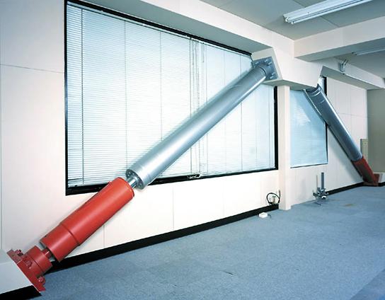
7 Why are Linear Systems Important? 7
8 Why are Linear Systems Important? Many important examples Electronic circuits Many important tools Frequency and step response, Traditional tools of control theory Developed in 93 s at Bell Labs Classical control design toolbox Nyquist plots, gain/phase margin Loop shaping CDS q 2 u(t) Optimal control and estimators Linear quadratic regulators Kalman estimators CDS 2 q k m m 2 k 2 k 3 c Robust control design H control design µ analysis for structured uncertainty CDS 22/ 23 8

 leads to")
, the system is time invariant")

9 Solutions of Linear Time Invariant Systems: The Matrix Exponential Linear Time Invariant (LTI) System: If Linear System input u(t) leads to output y(t) If u(t+t) leads to output y(t+t), the system is time invariant Scalar LTI system, with no input Matrix LTI system, with no input Matrix Exponential 9
10 The Matrix Exponential Recall scalar exponential formula: ee xx = + xx + xx2 + xx3! 2! 3! +, < xx < Matrix exponential defined analogously: ee MM = II +! MM + 2! MM2 + 3! MM3 + = Some useful properties of the Matrix Exponential If MM = mm mm nnnn, then ee MM = kk= kk! MMkk ee mm ee mm nnnn If matrix Y is invertible, then ee YYYYYY = YYee MM YY If M is diagonalizable (MM = TTTTTT ), then ee MM = TTee DD TT
11 The Convolution Integral: Step Let HH tt denote the response of a LTI system to a unit step input at t=. Assuming the system starts at Equilibrium The response to the steps are: First step input at time t=: HH tt tt uu tt Second step input at time tt : HH tt tt (uu tt uu tt ) Third step input at time tt 2 : HH tt tt 2 (uu tt 2 uu tt ) By linearity, we can add the response yy tt = HH tt tt uu tt + HH tt tt uu tt uu tt + = HH tt tt HH tt tt uu tt + HH tt tt HH tt tt 2 uu(tt ) + tt <tt = HH tt tt nn HH tt tt nn+ tt nn+ tt nn nn= Taking the limit as tt nn+ tt nn yy tt = HH tt uu(tt nn )(tt nn+ tt nn ) tt ττ uu ττ dddd
12 Impulse Response What is the impulse response due to u(t)=δ(t)? take limit as dt! but keep unit area u /dt homogeneous dt t Apply this unit impulse to the system (with x()=): Analogous to discrete-time response to input at time zero
13 Response to inputs: Convolution Impulse response, h(t) = Ce At B Response to input impulse Equivalent to Green s function homogeneous Linearity compose response to arbitrary u(t) using convolution Decompose input into sum of shifted impulse functions Compute impulse response for each Sum impulse response to find y(t) Take limit as dt Complete solution: use integral instead of sum linear with respect to initial condition and input 2X input 2X output when x() = 3
![Matlab/Python Tools for Linear Systems A = [- ; -]; B = [; ]; C = [ ]; D = []; x = [;.](/docs-images/84/89723128/images/14-2.jpg "5]; sys = ss(a,b,c,d); initial(sys, x); impulse(sys); t = :.:; u =.")

14 Matlab/Python Tools for Linear Systems A = [- ; -]; B = [; ]; C = [ ]; D = []; x = [;.5]; sys = ss(a,b,c,d); initial(sys, x); impulse(sys); t = :.:; u =.2*sin(5*t) + cos(2*t); lsim(sys, u, t, x); Amplitude Amplitude To: Y() To: Y() Initial Condition Results Linear Simulation Results Other MATLAB commands gensig, square, sawtooth produce signals of diff. types step, impulse, initial, lsim time domain analysis bode, freqresp, evalfr frequency domain analysis Time (sec.) ltiview linear time invariant system plots 4

15 Input/Output Performance Return to system with inputs How does system response to changes in input values? Transient response: What happens right after a new input is applied Transient Steady State Steady state response: What happens a long time after the input is applied Stability vs input/output performance Systems that are close to instability typically exhibit poor input/output performance Nearly unstable systems (slow convergence) often exhibit ringing (highly oscillatory response to [non-periodic] inputs) Mass spring system (L2.) 5
 of final value Steady state value: final value at t =.5 Overshoot Amplitude.5 Rise time Settling time Steady state value 5 5 2 25 Time (sec.")
16 Step Response Output characteristics in response to a step input Rise time: time required to move from 5% to 95% of final value Overshoot: ratio between amplitude of first peak and steady state value Settling time: time required to remain w/in p% (usually 2%) of final value Steady state value: final value at t =.5 Overshoot Amplitude.5 Rise time Settling time Steady state value Time (sec.) 6
 2.8.6.4 T=2π/ω.2 y.8.6.4 ζ.")
17 Second Order Systems Many important examples: Insight to response for higher orders (eigenvalues of A are either real or complex) Exception is non-diagonalizable A (non-trivial Jordan form) T=2π/ω.2 y ζ time (sec) Analytical formulas exist for overshoot, rise time, settling time, etc Will study more next week 7


 <")

18 Stability of Linear Systems Q: when is the system asymptotically stable? Stability is determined by the eigenvalues of the matrix A Simple case: diagonal system Stable if λ ii Asy stable if λ ii < Unstable if λ ii > More generally: transform to Jordan form Asy stable if Re(λ ii ) < Unstable if Re(λ ii ) > Indeterminate if Re( i ) = Form of eigenvalues determines system behavior Linear systems are automatically globally stable or unstable 8
 < Real e-values")
 = Complex e-values")
19 Eigenstructure of Linear Systems Real e-values Re(λ i ) < Real e-values Re(λ i ) < Re(λ i ) > Complex e-values Re(λ i ) = Complex e-values Re(λ i ) < 9
20 Frequency Response Measure steady state response of system to sinusoidal input Example: audio amplifier would like consistent ( flat ) amplification between 2 Hz & 2, Hz Individual sinusoids are good test signals for measuring performance in many systems Approach: plot input and output, measure relative amplitude and phase Use MATLAB or SIMULINK to generate response of system to sinusoidal output Gain = A y /A u Phase = 2π ΔT/T May not work for nonlinear systems System nonlinearities can cause harmonics to appear in the output Amplitude and phase may not be well-defined For linear systems, frequency response is always well defined Amplitude.5 u A u A y Time (sec.) ΔT T y 2
21 Computing Frequency Responses Technique #: plot input and output, measure relative amplitude and phase Generate response of system to sinusoidal output.5 u A u y Gain = A y /A u Phase = 2π ΔT/T For linear system, gain and phase don t depend on the input amplitude A y ΔT T Technique #2 (linear systems): use bode (or freqresp) command Assumes linear dynamics in state space form: Gain plotted on log-log scale db = 2 log (gain) Phase plotted on linear-log scale Phase (deg) Magnitude (db) bode(ss(a,b,c,d)) -36. Frequency (rad/sec) 2
22 Calculating Frequency Response from convolution equation (more later) Convolution equation describes response to any input; use this to look at response to sinusoidal input: u(t) Transient (decays if stable) Ratio of response/input Frequency response 22
23 q k q 2 u(t) m m 2 k 2 Spring Mass System k 3 c Eigenvalues of A: Frequency response: C(jωI-A) - B+D For zero damping, jω and jω 2 ω and ω 2 correspond frequency response peaks The eigenvectors for these eigenvalues give the mode shape: In-phase motion for lower freq. Out-of phase motion for higher freq. Frequency Response Phase [deg] Gain (log scale) Frequency [rad/sec]. 23
24 Summary: Linear Systems u y Properties of linear systems Linearity with respect to initial condition and inputs Stability characterized by eigenvalues Many applications and tools available Provide local description for nonlinear systems 24


25 Linearization Around an Equilibrium Point 2 Linearize around x=x e x x Remarks In examples, this is often equivalent to small angle approximations, etc Only works near to equilibrium point Full nonlinear model Linear model (honest!) 25
26 Example: Inverted Pendulum on a Cart m f x M State: Input: u = F Output: y = x Linearize according to previous formula around = 27
CDS 101/110: Lecture 3.1 Linear Systems
 CDS /: Lecture 3. Linear Systems Goals for Today: Revist and motivate linear time-invariant system models: Summarize properties, examples, and tools Convolution equation describing solution in response
CDS 101: Lecture 4.1 Linear Systems
 CDS : Lecture 4. Linear Systems Richard M. Murray 8 October 4 Goals: Describe linear system models: properties, eamples, and tools Characterize stability and performance of linear systems in terms of eigenvalues
CDS 101/110: Lecture 6.2 Transfer Functions
 CDS 11/11: Lecture 6.2 Transfer Functions November 2, 216 Goals: Continued study of Transfer functions Review Laplace Transform Block Diagram Algebra Bode Plot Intro Reading: Åström and Murray, Feedback
Time Domain Analysis of Linear Systems Ch2. University of Central Oklahoma Dr. Mohamed Bingabr
 Time Domain Analysis of Linear Systems Ch2 University of Central Oklahoma Dr. Mohamed Bingabr Outline Zero-input Response Impulse Response h(t) Convolution Zero-State Response System Stability System Response
Outline. Classical Control. Lecture 1
 Outline Outline Outline 1 Introduction 2 Prerequisites Block diagram for system modeling Modeling Mechanical Electrical Outline Introduction Background Basic Systems Models/Transfers functions 1 Introduction
Control Systems I. Lecture 6: Poles and Zeros. Readings: Emilio Frazzoli. Institute for Dynamic Systems and Control D-MAVT ETH Zürich
 Control Systems I Lecture 6: Poles and Zeros Readings: Emilio Frazzoli Institute for Dynamic Systems and Control D-MAVT ETH Zürich October 27, 2017 E. Frazzoli (ETH) Lecture 6: Control Systems I 27/10/2017
Systems Analysis and Control
 Systems Analysis and Control Matthew M. Peet Arizona State University Lecture 21: Stability Margins and Closing the Loop Overview In this Lecture, you will learn: Closing the Loop Effect on Bode Plot Effect
CDS 101/110a: Lecture 10-2 Control Systems Implementation
 CDS 101/110a: Lecture 10-2 Control Systems Implementation Richard M. Murray 5 December 2012 Goals Provide an overview of the key principles, concepts and tools from control theory - Classical control -
CDS 101/110a: Lecture 8-1 Frequency Domain Design
 CDS 11/11a: Lecture 8-1 Frequency Domain Design Richard M. Murray 17 November 28 Goals: Describe canonical control design problem and standard performance measures Show how to use loop shaping to achieve
Introduction to Modern Control MT 2016
 CDT Autonomous and Intelligent Machines & Systems Introduction to Modern Control MT 2016 Alessandro Abate Lecture 2 First-order ordinary differential equations (ODE) Solution of a linear ODE Hints to nonlinear
CDS 101/110a: Lecture 10-1 Robust Performance
 CDS 11/11a: Lecture 1-1 Robust Performance Richard M. Murray 1 December 28 Goals: Describe how to represent uncertainty in process dynamics Describe how to analyze a system in the presence of uncertainty
Dr. Ian R. Manchester
 Dr Ian R. Manchester Week Content Notes 1 Introduction 2 Frequency Domain Modelling 3 Transient Performance and the s-plane 4 Block Diagrams 5 Feedback System Characteristics Assign 1 Due 6 Root Locus
ECSE 4962 Control Systems Design. A Brief Tutorial on Control Design
 ECSE 4962 Control Systems Design A Brief Tutorial on Control Design Instructor: Professor John T. Wen TA: Ben Potsaid http://www.cat.rpi.edu/~wen/ecse4962s04/ Don t Wait Until The Last Minute! You got
Dr Ian R. Manchester Dr Ian R. Manchester AMME 3500 : Review
 Week Date Content Notes 1 6 Mar Introduction 2 13 Mar Frequency Domain Modelling 3 20 Mar Transient Performance and the s-plane 4 27 Mar Block Diagrams Assign 1 Due 5 3 Apr Feedback System Characteristics
CDS 101: Lecture 5-1 Reachability and State Space Feedback
 CDS 11: Lecture 5-1 Reachability and State Space Feedback Richard M. Murray 23 October 26 Goals: Define reachability of a control system Give tests for reachability of linear systems and apply to examples
Control Systems I Lecture 10: System Specifications
 Control Systems I Lecture 10: System Specifications Readings: Guzzella, Chapter 10 Emilio Frazzoli Institute for Dynamic Systems and Control D-MAVT ETH Zürich November 24, 2017 E. Frazzoli (ETH) Lecture
Control Systems I. Lecture 4: Diagonalization, Modal Analysis, Intro to Feedback. Readings: Emilio Frazzoli
 Control Systems I Lecture 4: Diagonalization, Modal Analysis, Intro to Feedback Readings: Emilio Frazzoli Institute for Dynamic Systems and Control D-MAVT ETH Zürich October 13, 2017 E. Frazzoli (ETH)
STABILITY. Have looked at modeling dynamic systems using differential equations. and used the Laplace transform to help find step and impulse
 SIGNALS AND SYSTEMS: PAPER 3C1 HANDOUT 4. Dr David Corrigan 1. Electronic and Electrical Engineering Dept. corrigad@tcd.ie www.sigmedia.tv STABILITY Have looked at modeling dynamic systems using differential
Frequency methods for the analysis of feedback systems. Lecture 6. Loop analysis of feedback systems. Nyquist approach to study stability
 Lecture 6. Loop analysis of feedback systems 1. Motivation 2. Graphical representation of frequency response: Bode and Nyquist curves 3. Nyquist stability theorem 4. Stability margins Frequency methods
Linear Systems. Chapter Basic Definitions
 Chapter 5 Linear Systems Few physical elements display truly linear characteristics. For example the relation between force on a spring and displacement of the spring is always nonlinear to some degree.
Control Systems I. Lecture 5: Transfer Functions. Readings: Emilio Frazzoli. Institute for Dynamic Systems and Control D-MAVT ETH Zürich
 Control Systems I Lecture 5: Transfer Functions Readings: Emilio Frazzoli Institute for Dynamic Systems and Control D-MAVT ETH Zürich October 20, 2017 E. Frazzoli (ETH) Lecture 5: Control Systems I 20/10/2017
MASSACHUSETTS INSTITUTE OF TECHNOLOGY Department of Mechanical Engineering Dynamics and Control II Fall 2007
 MASSACHUSETTS INSTITUTE OF TECHNOLOGY Department of Mechanical Engineering.4 Dynamics and Control II Fall 7 Problem Set #9 Solution Posted: Sunday, Dec., 7. The.4 Tower system. The system parameters are
CALIFORNIA INSTITUTE OF TECHNOLOGY Control and Dynamical Systems
 CDS 101 1. For each of the following linear systems, determine whether the origin is asymptotically stable and, if so, plot the step response and frequency response for the system. If there are multiple
Dynamic Response. Assoc. Prof. Enver Tatlicioglu. Department of Electrical & Electronics Engineering Izmir Institute of Technology.
 Dynamic Response Assoc. Prof. Enver Tatlicioglu Department of Electrical & Electronics Engineering Izmir Institute of Technology Chapter 3 Assoc. Prof. Enver Tatlicioglu (EEE@IYTE) EE362 Feedback Control
APPPHYS 217 Tuesday 6 April 2010
 APPPHYS 7 Tuesday 6 April Stability and input-output performance: second-order systems Here we present a detailed example to draw connections between today s topics and our prior review of linear algebra
CDS 110: Lecture 2-2 Modeling Using Differential Equations
 CDS 110: Lecture 2-2 Modeling Using Differential Equations Richard M. Murray and Hideo Mabuchi 4 October 2006 Goals: Provide a more detailed description of the use of ODEs for modeling Provide examples
Control Systems I. Lecture 7: Feedback and the Root Locus method. Readings: Jacopo Tani. Institute for Dynamic Systems and Control D-MAVT ETH Zürich
 Control Systems I Lecture 7: Feedback and the Root Locus method Readings: Jacopo Tani Institute for Dynamic Systems and Control D-MAVT ETH Zürich November 2, 2018 J. Tani, E. Frazzoli (ETH) Lecture 7:
Systems Analysis and Control
 Systems Analysis and Control Matthew M. Peet Arizona State University Lecture 8: Response Characteristics Overview In this Lecture, you will learn: Characteristics of the Response Stability Real Poles
Systems Analysis and Control
 Systems Analysis and Control Matthew M. Peet Illinois Institute of Technology Lecture 8: Response Characteristics Overview In this Lecture, you will learn: Characteristics of the Response Stability Real
Classify a transfer function to see which order or ramp it can follow and with which expected error.
 Dr. J. Tani, Prof. Dr. E. Frazzoli 5-059-00 Control Systems I (Autumn 208) Exercise Set 0 Topic: Specifications for Feedback Systems Discussion: 30.. 208 Learning objectives: The student can grizzi@ethz.ch,
ẋ n = f n (x 1,...,x n,u 1,...,u m ) (5) y 1 = g 1 (x 1,...,x n,u 1,...,u m ) (6) y p = g p (x 1,...,x n,u 1,...,u m ) (7)
 (5) y 1 = g 1 (x 1,...,x n,u 1,...,u m ) (6) y p = g p (x 1,...,x n,u 1,...,u m ) (7)") EEE582 Topical Outline A.A. Rodriguez Fall 2007 GWC 352, 965-3712 The following represents a detailed topical outline of the course. It attempts to highlight most of the key concepts to be covered and
EEE582 Topical Outline A.A. Rodriguez Fall 2007 GWC 352, 965-3712 The following represents a detailed topical outline of the course. It attempts to highlight most of the key concepts to be covered and
Digital Control Systems
 Digital Control Systems Lecture Summary #4 This summary discussed some graphical methods their use to determine the stability the stability margins of closed loop systems. A. Nyquist criterion Nyquist
D(s) G(s) A control system design definition
 G(s) A control system design definition") R E Compensation D(s) U Plant G(s) Y Figure 7. A control system design definition x x x 2 x 2 U 2 s s 7 2 Y Figure 7.2 A block diagram representing Eq. (7.) in control form z U 2 s z Y 4 z 2 s z 2 3 Figure
R E Compensation D(s) U Plant G(s) Y Figure 7. A control system design definition x x x 2 x 2 U 2 s s 7 2 Y Figure 7.2 A block diagram representing Eq. (7.) in control form z U 2 s z Y 4 z 2 s z 2 3 Figure
Richiami di Controlli Automatici
 Richiami di Controlli Automatici Gianmaria De Tommasi 1 1 Università degli Studi di Napoli Federico II detommas@unina.it Ottobre 2012 Corsi AnsaldoBreda G. De Tommasi (UNINA) Richiami di Controlli Automatici
State Regulator. Advanced Control. design of controllers using pole placement and LQ design rules
 Advanced Control State Regulator Scope design of controllers using pole placement and LQ design rules Keywords pole placement, optimal control, LQ regulator, weighting matrixes Prerequisites Contact state
CDS 101/110: Lecture 10.3 Final Exam Review
 CDS 11/11: Lecture 1.3 Final Exam Review December 2, 216 Schedule: (1) Posted on the web Monday, Dec. 5 by noon. (2) Due Friday, Dec. 9, at 5: pm. (3) Determines 3% of your grade Instructions on Front
Appendix 3B MATLAB Functions for Modeling and Time-domain analysis
 Appendix 3B MATLAB Functions for Modeling and Time-domain analysis MATLAB control system Toolbox contain the following functions for the time-domain response step impulse initial lsim gensig damp ltiview
Control of Mobile Robots
 Control of Mobile Robots Regulation and trajectory tracking Prof. Luca Bascetta (luca.bascetta@polimi.it) Politecnico di Milano Dipartimento di Elettronica, Informazione e Bioingegneria Organization and
MASSACHUSETTS INSTITUTE OF TECHNOLOGY Department of Mechanical Engineering 2.04A Systems and Controls Spring 2013
 MASSACHUSETTS INSTITUTE OF TECHNOLOGY Department of Mechanical Engineering 2.04A Systems and Controls Spring 2013 Problem Set #4 Posted: Thursday, Mar. 7, 13 Due: Thursday, Mar. 14, 13 1. Sketch the Root
Linear State Feedback Controller Design
 Assignment For EE5101 - Linear Systems Sem I AY2010/2011 Linear State Feedback Controller Design Phang Swee King A0033585A Email: king@nus.edu.sg NGS/ECE Dept. Faculty of Engineering National University
Digital Control: Part 2. ENGI 7825: Control Systems II Andrew Vardy
 Digital Control: Part 2 ENGI 7825: Control Systems II Andrew Vardy Mapping the s-plane onto the z-plane We re almost ready to design a controller for a DT system, however we will have to consider where
Introduction to Feedback Control
 Introduction to Feedback Control Control System Design Why Control? Open-Loop vs Closed-Loop (Feedback) Why Use Feedback Control? Closed-Loop Control System Structure Elements of a Feedback Control System
Automatic Control 2. Loop shaping. Prof. Alberto Bemporad. University of Trento. Academic year
 Automatic Control 2 Loop shaping Prof. Alberto Bemporad University of Trento Academic year 21-211 Prof. Alberto Bemporad (University of Trento) Automatic Control 2 Academic year 21-211 1 / 39 Feedback
(b) A unity feedback system is characterized by the transfer function. Design a suitable compensator to meet the following specifications:
 A unity feedback system is characterized by the transfer function. Design a suitable compensator to meet the following specifications:") 1. (a) The open loop transfer function of a unity feedback control system is given by G(S) = K/S(1+0.1S)(1+S) (i) Determine the value of K so that the resonance peak M r of the system is equal to 1.4.
1. (a) The open loop transfer function of a unity feedback control system is given by G(S) = K/S(1+0.1S)(1+S) (i) Determine the value of K so that the resonance peak M r of the system is equal to 1.4.
Discrete Systems. Step response and pole locations. Mark Cannon. Hilary Term Lecture
 Discrete Systems Mark Cannon Hilary Term 22 - Lecture 4 Step response and pole locations 4 - Review Definition of -transform: U() = Z{u k } = u k k k= Discrete transfer function: Y () U() = G() = Z{g k},
Dynamic circuits: Frequency domain analysis
 Electronic Circuits 1 Dynamic circuits: Contents Free oscillation and natural frequency Transfer functions Frequency response Bode plots 1 System behaviour: overview 2 System behaviour : review solution
Control Systems Design
 ELEC4410 Control Systems Design Lecture 13: Stability Julio H. Braslavsky julio@ee.newcastle.edu.au School of Electrical Engineering and Computer Science Lecture 13: Stability p.1/20 Outline Input-Output
Process Control & Instrumentation (CH 3040)
") First-order systems Process Control & Instrumentation (CH 3040) Arun K. Tangirala Department of Chemical Engineering, IIT Madras January - April 010 Lectures: Mon, Tue, Wed, Fri Extra class: Thu A first-order
First-order systems Process Control & Instrumentation (CH 3040) Arun K. Tangirala Department of Chemical Engineering, IIT Madras January - April 010 Lectures: Mon, Tue, Wed, Fri Extra class: Thu A first-order
Lecture 12. Upcoming labs: Final Exam on 12/21/2015 (Monday)10:30-12:30
10:30-12:30") 289 Upcoming labs: Lecture 12 Lab 20: Internal model control (finish up) Lab 22: Force or Torque control experiments [Integrative] (2-3 sessions) Final Exam on 12/21/2015 (Monday)10:30-12:30 Today: Recap
289 Upcoming labs: Lecture 12 Lab 20: Internal model control (finish up) Lab 22: Force or Torque control experiments [Integrative] (2-3 sessions) Final Exam on 12/21/2015 (Monday)10:30-12:30 Today: Recap
Homework 7 - Solutions
 Homework 7 - Solutions Note: This homework is worth a total of 48 points. 1. Compensators (9 points) For a unity feedback system given below, with G(s) = K s(s + 5)(s + 11) do the following: (c) Find the
ECE 3793 Matlab Project 3 Solution
 ECE 3793 Matlab Project 3 Solution Spring 27 Dr. Havlicek. (a) In text problem 9.22(d), we are given X(s) = s + 2 s 2 + 7s + 2 4 < Re {s} < 3. The following Matlab statements determine the partial fraction
6.1 Sketch the z-domain root locus and find the critical gain for the following systems K., the closed-loop characteristic equation is K + z 0.
 6. Sketch the z-domain root locus and find the critical gain for the following systems K (i) Gz () z 4. (ii) Gz K () ( z+ 9. )( z 9. ) (iii) Gz () Kz ( z. )( z ) (iv) Gz () Kz ( + 9. ) ( z. )( z 8. ) (i)
Lab Experiment 2: Performance of First order and second order systems
 Lab Experiment 2: Performance of First order and second order systems Objective: The objective of this exercise will be to study the performance characteristics of first and second order systems using
Today (10/23/01) Today. Reading Assignment: 6.3. Gain/phase margin lead/lag compensator Ref. 6.4, 6.7, 6.10
 Today. Reading Assignment: 6.3. Gain/phase margin lead/lag compensator Ref. 6.4, 6.7, 6.10") Today Today (10/23/01) Gain/phase margin lead/lag compensator Ref. 6.4, 6.7, 6.10 Reading Assignment: 6.3 Last Time In the last lecture, we discussed control design through shaping of the loop gain GK:
Today Today (10/23/01) Gain/phase margin lead/lag compensator Ref. 6.4, 6.7, 6.10 Reading Assignment: 6.3 Last Time In the last lecture, we discussed control design through shaping of the loop gain GK:
Systems Analysis and Control
 Systems Analysis and Control Matthew M. Peet Arizona State University Lecture 23: Drawing The Nyquist Plot Overview In this Lecture, you will learn: Review of Nyquist Drawing the Nyquist Plot Using the
CHAPTER 7 : BODE PLOTS AND GAIN ADJUSTMENTS COMPENSATION
 CHAPTER 7 : BODE PLOTS AND GAIN ADJUSTMENTS COMPENSATION Objectives Students should be able to: Draw the bode plots for first order and second order system. Determine the stability through the bode plots.
5HC99 Embedded Vision Control. Feedback Control Systems. dr. Dip Goswami Flux Department of Electrical Engineering
 5HC99 Embedded Vision Control Feedback Control Systems dr. Dip Goswami d.goswami@tue.nl Flux 04.135 Department of Electrical Engineering 1 Example Feedback control system: regulates the behavior of dynamical
INTRODUCTION TO DIGITAL CONTROL
 ECE4540/5540: Digital Control Systems INTRODUCTION TO DIGITAL CONTROL.: Introduction In ECE450/ECE550 Feedback Control Systems, welearnedhow to make an analog controller D(s) to control a linear-time-invariant
ECE-320: Linear Control Systems Homework 8. 1) For one of the rectilinear systems in lab, I found the following state variable representations:
 For one of the rectilinear systems in lab, I found the following state variable representations:") ECE-30: Linear Control Systems Homework 8 Due: Thursday May 6, 00 at the beginning of class ) For one of the rectilinear systems in lab, I found the following state variable representations: 0 0 q q+ 74.805.6469
ECE-30: Linear Control Systems Homework 8 Due: Thursday May 6, 00 at the beginning of class ) For one of the rectilinear systems in lab, I found the following state variable representations: 0 0 q q+ 74.805.6469
ECE317 : Feedback and Control
 ECE317 : Feedback and Control Lecture : Steady-state error Dr. Richard Tymerski Dept. of Electrical and Computer Engineering Portland State University 1 Course roadmap Modeling Analysis Design Laplace
CDS 101/110a: Lecture 2.1 Dynamic Behavior
 CDS 11/11a: Lecture.1 Dynamic Behavior Richard M. Murray 6 October 8 Goals: Learn to use phase portraits to visualize behavior of dynamical systems Understand different types of stability for an equilibrium
LABORATORY INSTRUCTION MANUAL CONTROL SYSTEM I LAB EE 593
 LABORATORY INSTRUCTION MANUAL CONTROL SYSTEM I LAB EE 593 ELECTRICAL ENGINEERING DEPARTMENT JIS COLLEGE OF ENGINEERING (AN AUTONOMOUS INSTITUTE) KALYANI, NADIA CONTROL SYSTEM I LAB. MANUAL EE 593 EXPERIMENT
CDS 101/110a: Lecture 2.1 Dynamic Behavior
 CDS 11/11a: Lecture 2.1 Dynamic Behavior Richard M. Murray 6 October 28 Goals: Learn to use phase portraits to visualize behavior of dynamical systems Understand different types of stability for an equilibrium
Dynamics of structures
 Dynamics of structures 2.Vibrations: single degree of freedom system Arnaud Deraemaeker (aderaema@ulb.ac.be) 1 One degree of freedom systems in real life 2 1 Reduction of a system to a one dof system Example
Prüfung Regelungstechnik I (Control Systems I) Übersetzungshilfe / Translation aid (English) To be returned at the end of the exam!
 Übersetzungshilfe / Translation aid (English) To be returned at the end of the exam!") Prüfung Regelungstechnik I (Control Systems I) Prof. Dr. Lino Guzzella 29. 8. 2 Übersetzungshilfe / Translation aid (English) To be returned at the end of the exam! Do not mark up this translation aid
Prüfung Regelungstechnik I (Control Systems I) Prof. Dr. Lino Guzzella 29. 8. 2 Übersetzungshilfe / Translation aid (English) To be returned at the end of the exam! Do not mark up this translation aid
EE C128 / ME C134 Fall 2014 HW 8 - Solutions. HW 8 - Solutions
 EE C28 / ME C34 Fall 24 HW 8 - Solutions HW 8 - Solutions. Transient Response Design via Gain Adjustment For a transfer function G(s) = in negative feedback, find the gain to yield a 5% s(s+2)(s+85) overshoot
Differential Equations and Lumped Element Circuits
 Differential Equations and Lumped Element Circuits 8 Introduction Chapter 8 of the text discusses the numerical solution of ordinary differential equations. Differential equations and in particular linear
Control of Manufacturing Processes
 Control of Manufacturing Processes Subject 2.830 Spring 2004 Lecture #19 Position Control and Root Locus Analysis" April 22, 2004 The Position Servo Problem, reference position NC Control Robots Injection
Problem Weight Total 100
 EE 350 Problem Set 3 Cover Sheet Fall 2016 Last Name (Print): First Name (Print): ID number (Last 4 digits): Section: Submission deadlines: Turn in the written solutions by 4:00 pm on Tuesday September
Topic # Feedback Control Systems
 Topic #19 16.31 Feedback Control Systems Stengel Chapter 6 Question: how well do the large gain and phase margins discussed for LQR map over to DOFB using LQR and LQE (called LQG)? Fall 2010 16.30/31 19
EE Homework 12 - Solutions. 1. The transfer function of the system is given to be H(s) = s j j
 = s j j") EE3054 - Homework 2 - Solutions. The transfer function of the system is given to be H(s) = s 2 +3s+3. Decomposing into partial fractions, H(s) = 0.5774j s +.5 0.866j + 0.5774j s +.5 + 0.866j. () (a) The
EE3054 - Homework 2 - Solutions. The transfer function of the system is given to be H(s) = s 2 +3s+3. Decomposing into partial fractions, H(s) = 0.5774j s +.5 0.866j + 0.5774j s +.5 + 0.866j. () (a) The
Time-Invariant Linear Quadratic Regulators Robert Stengel Optimal Control and Estimation MAE 546 Princeton University, 2015
 Time-Invariant Linear Quadratic Regulators Robert Stengel Optimal Control and Estimation MAE 546 Princeton University, 15 Asymptotic approach from time-varying to constant gains Elimination of cross weighting
Dr Ian R. Manchester
 Week Content Notes 1 Introduction 2 Frequency Domain Modelling 3 Transient Performance and the s-plane 4 Block Diagrams 5 Feedback System Characteristics Assign 1 Due 6 Root Locus 7 Root Locus 2 Assign
Module 06 Stability of Dynamical Systems
 Module 06 Stability of Dynamical Systems Ahmad F. Taha EE 5143: Linear Systems and Control Email: ahmad.taha@utsa.edu Webpage: http://engineering.utsa.edu/ataha October 10, 2017 Ahmad F. Taha Module 06
(a) Find the transfer function of the amplifier. Ans.: G(s) =
 Find the transfer function of the amplifier. Ans.: G(s) =") 126 INTRDUCTIN T CNTR ENGINEERING 10( s 1) (a) Find the transfer function of the amplifier. Ans.: (. 02s 1)(. 001s 1) (b) Find the expected percent overshoot for a step input for the closed-loop system
126 INTRDUCTIN T CNTR ENGINEERING 10( s 1) (a) Find the transfer function of the amplifier. Ans.: (. 02s 1)(. 001s 1) (b) Find the expected percent overshoot for a step input for the closed-loop system
APPLICATIONS FOR ROBOTICS
 Version: 1 CONTROL APPLICATIONS FOR ROBOTICS TEX d: Feb. 17, 214 PREVIEW We show that the transfer function and conditions of stability for linear systems can be studied using Laplace transforms. Table
Review: transient and steady-state response; DC gain and the FVT Today s topic: system-modeling diagrams; prototype 2nd-order system
 Plan of the Lecture Review: transient and steady-state response; DC gain and the FVT Today s topic: system-modeling diagrams; prototype 2nd-order system Plan of the Lecture Review: transient and steady-state
Lecture 5: Frequency domain analysis: Nyquist, Bode Diagrams, second order systems, system types
 Lecture 5: Frequency domain analysis: Nyquist, Bode Diagrams, second order systems, system types Venkata Sonti Department of Mechanical Engineering Indian Institute of Science Bangalore, India, 562 This
MAE143a: Signals & Systems (& Control) Final Exam (2011) solutions
 Final Exam (2011) solutions") MAE143a: Signals & Systems (& Control) Final Exam (2011) solutions Question 1. SIGNALS: Design of a noise-cancelling headphone system. 1a. Based on the low-pass filter given, design a high-pass filter,
MAE143a: Signals & Systems (& Control) Final Exam (2011) solutions Question 1. SIGNALS: Design of a noise-cancelling headphone system. 1a. Based on the low-pass filter given, design a high-pass filter,
agree w/input bond => + sign disagree w/input bond => - sign
 1 ME 344 REVIEW FOR FINAL EXAM LOCATION: CPE 2.204 M. D. BRYANT DATE: Wednesday, May 7, 2008 9-noon Finals week office hours: May 6, 4-7 pm Permitted at final exam: 1 sheet of formulas & calculator I.
AMME3500: System Dynamics & Control
 Stefan B. Williams May, 211 AMME35: System Dynamics & Control Assignment 4 Note: This assignment contributes 15% towards your final mark. This assignment is due at 4pm on Monday, May 3 th during Week 13
Systems Analysis and Control
 Systems Analysis and Control Matthew M. Peet Illinois Institute of Technology Lecture : Different Types of Control Overview In this Lecture, you will learn: Limits of Proportional Feedback Performance
Problem Weight Score Total 100
 EE 350 EXAM IV 15 December 2010 Last Name (Print): First Name (Print): ID number (Last 4 digits): Section: DO NOT TURN THIS PAGE UNTIL YOU ARE TOLD TO DO SO Problem Weight Score 1 25 2 25 3 25 4 25 Total
EEE582 Homework Problems
 EEE582 Homework Problems HW. Write a state-space realization of the linearized model for the cruise control system around speeds v = 4 (Section.3, http://tsakalis.faculty.asu.edu/notes/models.pdf). Use
Return Difference Function and Closed-Loop Roots Single-Input/Single-Output Control Systems
 Spectral Properties of Linear- Quadratic Regulators Robert Stengel Optimal Control and Estimation MAE 546 Princeton University, 2018! Stability margins of single-input/singleoutput (SISO) systems! Characterizations
Transient Response of a Second-Order System
 Transient Response of a Second-Order System ECEN 830 Spring 01 1. Introduction In connection with this experiment, you are selecting the gains in your feedback loop to obtain a well-behaved closed-loop
Systems Analysis and Control
 Systems Analysis and Control Matthew M. Peet Illinois Institute of Technology Lecture 23: Drawing The Nyquist Plot Overview In this Lecture, you will learn: Review of Nyquist Drawing the Nyquist Plot Using
CDS 101/110a: Lecture 1.1 Introduction to Feedback & Control. CDS 101/110 Course Sequence
 CDS 101/110a: Lecture 1.1 Introduction to Feedback & Control Richard M. Murray 28 September 2015 Goals: Give an overview of CDS 101/110: course structure & administration Define feedback systems and learn
Time-Invariant Linear Quadratic Regulators!
 Time-Invariant Linear Quadratic Regulators Robert Stengel Optimal Control and Estimation MAE 546 Princeton University, 17 Asymptotic approach from time-varying to constant gains Elimination of cross weighting
L2 gains and system approximation quality 1
 Massachusetts Institute of Technology Department of Electrical Engineering and Computer Science 6.242, Fall 24: MODEL REDUCTION L2 gains and system approximation quality 1 This lecture discusses the utility
Lecture 9. Welcome back! Coming week labs: Today: Lab 16 System Identification (2 sessions)
") 232 Welcome back! Coming week labs: Lecture 9 Lab 16 System Identification (2 sessions) Today: Review of Lab 15 System identification (ala ME4232) Time domain Frequency domain 1 Future Labs To develop
232 Welcome back! Coming week labs: Lecture 9 Lab 16 System Identification (2 sessions) Today: Review of Lab 15 System identification (ala ME4232) Time domain Frequency domain 1 Future Labs To develop
Active Control? Contact : Website : Teaching
 Active Control? Contact : bmokrani@ulb.ac.be Website : http://scmero.ulb.ac.be Teaching Active Control? Disturbances System Measurement Control Controler. Regulator.,,, Aims of an Active Control Disturbances
AUTOMATIC CONTROL. Andrea M. Zanchettin, PhD Spring Semester, Introduction to Automatic Control & Linear systems (time domain)
") 1 AUTOMATIC CONTROL Andrea M. Zanchettin, PhD Spring Semester, 2018 Introduction to Automatic Control & Linear systems (time domain) 2 What is automatic control? From Wikipedia Control theory is an interdisciplinary
1 AUTOMATIC CONTROL Andrea M. Zanchettin, PhD Spring Semester, 2018 Introduction to Automatic Control & Linear systems (time domain) 2 What is automatic control? From Wikipedia Control theory is an interdisciplinary
Laboratory handout 5 Mode shapes and resonance
 laboratory handouts, me 34 82 Laboratory handout 5 Mode shapes and resonance In this handout, material and assignments marked as optional can be skipped when preparing for the lab, but may provide a useful
EECS C128/ ME C134 Final Wed. Dec. 15, am. Closed book. Two pages of formula sheets. No calculators.
 Name: SID: EECS C28/ ME C34 Final Wed. Dec. 5, 2 8- am Closed book. Two pages of formula sheets. No calculators. There are 8 problems worth points total. Problem Points Score 2 2 6 3 4 4 5 6 6 7 8 2 Total
Lecture 25: Tue Nov 27, 2018
 Lecture 25: Tue Nov 27, 2018 Reminder: Lab 3 moved to Tuesday Dec 4 Lecture: review time-domain characteristics of 2nd-order systems intro to control: feedback open-loop vs closed-loop control intro to
Represent this system in terms of a block diagram consisting only of. g From Newton s law: 2 : θ sin θ 9 θ ` T
 Exercise (Block diagram decomposition). Consider a system P that maps each input to the solutions of 9 4 ` 3 9 Represent this system in terms of a block diagram consisting only of integrator systems, represented
Transient response via gain adjustment. Consider a unity feedback system, where G(s) = 2. The closed loop transfer function is. s 2 + 2ζωs + ω 2 n
 = 2. The closed loop transfer function is. s 2 + 2ζωs + ω 2 n") Design via frequency response Transient response via gain adjustment Consider a unity feedback system, where G(s) = ωn 2. The closed loop transfer function is s(s+2ζω n ) T(s) = ω 2 n s 2 + 2ζωs + ω 2
Design via frequency response Transient response via gain adjustment Consider a unity feedback system, where G(s) = ωn 2. The closed loop transfer function is s(s+2ζω n ) T(s) = ω 2 n s 2 + 2ζωs + ω 2
ECE 3793 Matlab Project 3
 ECE 3793 Matlab Project 3 Spring 2017 Dr. Havlicek DUE: 04/25/2017, 11:59 PM What to Turn In: Make one file that contains your solution for this assignment. It can be an MS WORD file or a PDF file. Make
Time Response of Systems
 Chapter 0 Time Response of Systems 0. Some Standard Time Responses Let us try to get some impulse time responses just by inspection: Poles F (s) f(t) s-plane Time response p =0 s p =0,p 2 =0 s 2 t p =