(Refer Slide Time: 0:55)
|
|
|
- Clarence Preston
- 5 years ago
- Views:
Transcription

1 Fluid Dynamics And Turbo Machines. Professor Dr Dhiman Chatterjee. Department Of Mechanical Engineering. Indian Institute Of Technology Madras. Part C. Module-2. Lecture-8. Hydraulic Turbines: Pelton Turbine. Good morning, I welcome you all for today s discussion on hydraulic turbines. In the last couple of lectures we talked about pumps and we talked about the classification of pumps. In the same way we will start the discussion on hydraulic turbines by first making the classification of hydraulic turbines. Before we go into hydraulic turbines, let me show you a schematic or picture of hydroelectric power plant. (Refer Slide Time: 0:55) Many of us, maybe some of you have also visited some dams, you could see on one side of the dam there will be a big pool of water, which we call the reservoir and through the dam, at the base of the dam you will have a powerhouse which has a typically a turbine as shown here. As water flows from the duct, it comes to the turbine, this is called the penstock, it comes to the turbine, then these turbine blades will rotate, there is a generator connected at the top which converts the rotations into electric current and then it goes out of the powerhouse for distribution. And that is how we generate hydroelectricity. Now it is not necessary in general that a hydraulic turbine will always have a dam, recent works are showing on low head turbines with no dam or very small check dams or barrages.
 These categories may vary from country to country.")
2 But the turbines that we are going to discuss today in this lecture are all big turbines, so for that dam and reservoir that were showing here schematically are essential components. So that means that we need to classify the hydro power plant projects into certain categories. (Refer Slide Time: 2:05) These categories may vary from country to country. These numbers, the names remain same pico, micro, mini, small, etc., the names remain same but these values that are given, the capacity values can change from country to country, what I am showing is for India specific. So in India we talk about pico powerplant stations or pico hydro power projects which produces 5 kilowatt or below. This is basically used for a system where you produce power locally and use it, it is not really for transmission and going for the grid, usually that is the scenario. Then we can have micro hydropower projects which is up to 100 kilowatts, between 101 kilowatt 2 megawatts, we can talk about mini hydropower projects, above 2 megawatts and up to 25 megawatts we talk about small hydropower projects and above that we have the large hydropower stations. So this is the classification which we normally have and for these larger power stations, we really have the dams and the turbines that we are going to talk about.
3 (Refer Slide Time: 3:18) So some basic concepts that we need to be clear at the very beginning. In case of pump for example we had talked about the head developed by the pump. Here we are talking about what is the head utilised by the turbine. So we can say that there is a headrest level, you can imagine that this headrest level is nothing but the reservoir we have talked about and there is a tail rest level at the downstream side of the turbine and in between the headrest level and the tail rest level we have a turbine which is installed. So we have a piping system which you call the penstock which brings the water to the turbine. Now you may say that this level difference, this geodetic level difference between the headrest level and the tail rest level is the head available. Yes it is true it is the head available, it is called the gross head or Hg in my notations. So this gross head is nothing but the geodetic level difference between the headrest level and the tail rest level. However, whenever there is a flow, there will be some losses associated with it, there can be approached loss, there can be exit losses and hence what is available to the turbine for extraction of power is not Hg. What is available is the energy available with the fluid before it enters the turbine here and the energy available with the flow as it leaves the turbine. And this is given by another symbol called H net or H. So this H is called the net head as opposed to HG which is the gross head. And the difference between the 2 is accounted for by the losses. I am not going to what are the different losses that this stage, it is not required. So whenever we discuss about
 Thus we can say that net head or head is equal to HG - loss and this is strictly speaking should be called net head but we use the term head.")
4 the head utilised by the turbine, unless specifically mentioned, we always refer to the head or the net head. (Refer Slide Time: 5:22) Thus we can say that net head or head is equal to HG - loss and this is strictly speaking should be called net head but we use the term head. And we can say that if there are no losses in the turbine, if you assume the turbine to be an idealised machine, which is not in reality, then the ideal or the theoretical power that will be transmitted by this turbine is P theoretical, PH here stands for theoretical or ideal is rho V dot gh. But as we have discussed in thermodynamics and also when we talked about the different losses in the earlier classes, we said that no machine can be hundred percent efficient, we also discussed different losses that are present for example we talked about hydraulic losses, we have talked about, inside the hydraulic losses we have talked about the friction losses as well as a shock or incidence loss, we have talked about the leakage loss, we have talked about disc friction loss, we have talked about return flow loss. Now return flow loss in case of turbine is not very significant. And the disc friction loss is generally applicable for turbines, except for the turbine which is moving in air. So we will talk about Pelton turbine which actually moves in air. So you have to account for these different losses. And what we ultimately get from the turbine is the coupling power PC which is given by omega, the rotational speed times T. And the ratio of the 2 is called the overall efficiency. This was already talked about when we discuss the

5 losses but I am bringing it here because this is the central concept that we have to keep in mind. (Refer Slide Time: 7:18) The ideal power, the actual power and the efficiency. Okay. So now when we come to the turbines, we can classify the turbines in different ways just like we can classify any Turbo machines we have discussed in general. So we can say that based on head and discharge, example qualitatively speaking I can say high head, medium head, low head or alternatively I can say high volume flow rate, medium volume flow rate or low volume flow rate. But the problem of this way of classifying is that how high is high, what is high and what is low, these are not very well defined. So we have to talk about in another way. I will come to that next. So right now we will talk about based on the action of water on the moving blades and we can say that the turbines can be classified into 2 categories, one is impulse type of turbine, another one is reaction type of turbine. You already know the definition of impulse type of turbine, impulse type of hydraulic turbine is a hydraulic turbine in which there is no change of static pressure in the impeller or the runner or the rotor blades. Reaction turbine is one in which there is a change in the pressure. So different types of impulse turbines are possible Pelton turbine, Turgo turbine and Banki or crossflow turbine. And similarly reaction turbines can be of different types Francis, Deriaz, propeller and Kaplan. And you see that some of these Pelton, Francis and Kaplan are marked in red because
 So in this course on fluid dynamics and Turbo machines we are going to cover these 3 turbines in some detail. I will touch upon propeller turbine in the next lecture as well.")
6 this is what I am going to cover in today s lecture. We are going to talk about Pelton turbine, in the next lecture, in the next class we will talk about Francis and Kaplan turbine. (Refer Slide Time: 9:23) So in this course on fluid dynamics and Turbo machines we are going to cover these 3 turbines in some detail. I will touch upon propeller turbine in the next lecture as well. So we continue with the classification of hydraulic turbines. We can say based on the direction of flow of water in the runner and we can say it can be a tangential flow, in case of Pelton turbine, this will become clear when we see the picture of Pelton turbine or it can be mixed flow in case of Francis or axial flow in case of Kaplan or propeller turbine. So this picture will become clearer when we talk about the different turbines in some detail. And we can also tell based on the arrangement of the turbine shaft, the shaft can be arranged in the vertical or in the horizontal direction.

7 (Refer Slide Time: 10:02) But the best way of classifying Turbo machine as we have already discussed is based on the specific speed or shape number. We will use the specific speed definition here for hydraulic turbine. And based on it we can say that if the specific speed range is between 10 and 35 we would prefer Pelton turbine. If it is between 60 and 300, it is Francis turbine and above 300 it is usually Kaplan turbine. And to remind you, this definition of specific speed Ns is given as N under root PC which is the coupling power whole divided by H to the power 5 by 4. Please note that it is 5 by 4, whereas in case pump in the last class we have talked about with H the power three fourth. And also please note that this coupling power is in metric horsepower which is you can always convert from watt or kilowatt into metric horsepower. Then N is in RPM and H is in meters. Now you may say what is wrong if I use Pelton turbine in case of let us say a specific speed in the range of 120 to 180. The reason is that you will not get the best efficiency. So we are talking about using a particular type of turbine where the efficiency should be highest. So that has to be always kept in mind while determining which turbine is more appropriate.

8 (Refer Slide Time: 11:36) So some of the hydraulic turbine installations in India are, I have just given examples where Pelton, Francis or Kaplan turbines are involved. Pelton turbine is seen in Mussoorie hydroelectric powerplant on the Kiarkuli River, the Francis turbine is seen in the Bhakra dam and Kaplan turbine is found in the Hirakud dam. These some of the values of the operating conditions are given, you can calculate the specific speeds and see whether these satisfy. (Refer Slide Time: 12:04) Now we start with Pelton turbine. Let us first see the overall arrangement of Pelton turbine. The Pelton turbine essentially has a wheel or a drum which is the runner which rotates and on it some, you can see the these are called buckets, these are connected, we have a nozzle
9 which brings water, these are water jets which hits this bucket and as a result the bucket rotates in the direction shown by this curly arrow. Also we have what, inside this nozzle what is known as the spear arrangement, I will talk about this spear arrangement in detail because it is a very special mention, of course I will talk about the bucket as well. And in some cases we have the brake nozzle is, you see that the flow coming out of the main nozzle actually tries to take the bucket as shown in the direction. The water that is coming out of the brake nozzle hits on the opposite surface and is trying to act against the main direction of rotation. So it tries to slowdown the turbine. When do you require it, we will see it shortly. So these are the essential components. We also have more often than not a casing surrounding this Pelton turbine. Now one thing we have to be very clear, when we say Pelton turbine and we have said it is an impulse turbine, so what does it mean, pressure does not change. And in this case this jet of water issuing out of the nozzle is coming out in open atmosphere. So that means the Pelton turbine is essentially rotating under the impact of this jet of water striking the buckets in air. Now if it is in open air and the pressure is constant, then why do we need a casing? Yes that is a good question, the casing is not required for any hydraulic requirement, it is actually for our safety and also for preventing splashing of water. We will see that when we talk about the reaction turbines in the next class, we will see that casing is very very important component there. Okay, so this is the overall arrangement of a Pelton turbine. (Refer Slide Time: 14:43)
10
11 Now we will talk about each of these components in some detail, particularly the nozzle and the spear and the bucket which we can say are like the main components in case of a Pelton turbine. So first we will start with nozzle and spear. In a cartoon form, in a schematic form this is a nozzle, the nozzle exits here and the jet comes out, I have intentionally shown it in an exaggerated way, this is the portion which had the least diameter, the vena contractor and of course there is a remaining portion of the pen stock. Now we have a spear which is kept inside the nozzle. This spear can move, it can go and try to close the nozzle or it can open further, this reciprocating motion, if required, if the positioning of the spear inside the nozzle, that is if it is retracted fully or brought in fully kept somewhere in between, this dictates what will be the volume flow rate. So we can say that this volume flow rate happens because of the location of the spear and of course the head available today turbine. But why do we need such an arrangement? You can say that making the spear will be more expensive. We could have always done this work with the help of some simple valves. For example in our home when we want to control the water coming out in a tap, the tap itself is a valve, we are trying to close it, open it as we wish. So why do we need it? The reason is because we want minimum loss in this nozzle and hence what we want is the minimum restrictions in terms of the flow rate that is possible without incurring major loss. And hence the spear is an essential component, you cannot use any valves. And we can define few diameters, D0 is a nominal diameter of the nozzle exit and DJ is the diameter of the jet or jet diameter and more often than not we will use this jet diameter DJ than D0. And typical angle for nozzle is the 2 beta is the angle of the nozzle, we have used is 84 degrees and typical angle for the spear is 50 to 60 degrees. We are now going to talk more about the nozzle and the jet diameter.
12 (Refer Slide Time: 17:09) We can say that the volume that is coming out in the form of jet is given by V dot which is pie by 4 DJ square, that is the jet diameter, the area corresponding to the jet diameter multiplied by CJ. And what is CJ, CJ is nothing but some constant times in root 2 GH. How do you visualize the root 2 GH, you have studied in fluid dynamics that if we have a tank and we have water coming out of the tank, then what is the velocity that you get? The velocity is obtained by the change of potential energy. So the kinetic energy is obtained by the change of potential energy and hence velocity will be nothing but root 2 GH. So the jet is coming out in atmospheric condition because of the head imposed on the turbine which is capital H. And hence the velocity should be proportional to root 2 GH. But why is it KN, KN is called the nozzle velocity coefficient which varies from 0.98 to What does it show, that it is almost like an idealised state of 1. CJ would have been root 2 GH if there is no loss anywhere but because of very minimal loss, we find that KN is close to 1, not exactly one. And we can write the DJ is equal to under root 4V dot by pie KN under root 2 GH. So this is obtained from the relationship between V dot and CJ given earlier. We can in the same way right in the nominal diameter of the nozzle, in terms of the volume flow rate and a nozzle coefficient which is K C0 which is magnitude of 0.81 to So these are the more important diameters as far as the jet is concerned. Now this jet will hit the runner. So what will happen is this impact will now cause these motions, the momentum change will take place and will cause the motion. Let us now look at what happened there.
13 (Refer Slide Time: 19:28) When we talk about the specific speed, we have to also keep in mind the usual definition of the specific speed, we have given N under root PC by H to the power 5 by 4. We have the usual definition, so N is in RPM, PC is in metric horsepower or for the time being we can say it is close to kilowatt and H is in metres. In case of multiple jets, in Pelton turbine I have shown you the example where there is only one jet, if there are multiple jets come up to 6 jets are possible, these jets can hit the Pelton turbine bucket from 6 different locations and in this case the power output will be more and we can say that NSJ is nothing but, J is the number of jets, so is nothing but N under root J times PC whole divided by H to the power 5 by 4. And hence we can say that if there are J number of jets, then NSJ is under root times NS, this is the relationship we have to use. Why is it important because you saw that in case of Pelton turbine, the Pelton turbine can work between 10 to 35 and we have also seen that Francis turbine works in the range of 60 and above. Now you may come across a situation where the specific speed lies between 35 and 60. So what will you do? You can use multiple jets and try to accommodate that specific speed requirement. So you see that even if I say that the specific speed of an individual, one jet Pelton turbine is 35, if you have 4 jets, then under of 4 will give you 2, you are going close to 70. So you are actually bridging the gap between 35 to 60. So that is where many times the multiple jets are used but there is a restriction that you cannot go more than 6 from the practical considerations. So this is an important aspect about the jet, the choice of jets or number of nozzles you need to produce the power.
14 (Refer Slide Time: 21:54) Now we want to talk about the Pelton wheel diameter or Pelton wheel runner. So this is my schematic of the jet hitting a Pelton bucket, in the next slide we will talk more about the bucket, so this hits the bucket and as a result of the momentum change we will find that there is a net rotation is taking place in the nation shown by the arrow. This D is called the pitch circle diameter. This is where these Pelton buckets are connected with the runner or the wheel. Many times it is called the Pelton wheel. So on the, in the wheel you have to connect or fasten these buckets. Now we can say that if the rotational RPM is N, then U is nothing but pie ND by 60. Now what causes this rotation? It is a jet which is impinging on the buckets. So that means in a way it is related with the net head which is available for this turbine and hence we can say that U is equal to KU times under root 2 GH and we can say that KU is blade speed ratio which varies between 0.44 to And hence we can find out the diameter or the pitch circle diameter D as 60 KU times under root 2 GH by pie N.

15 (Refer Slide Time: 23:19) Working speed of a turbine depends on the nature of the driven unit. If an electrical generator has to be connected, we are directly coupling to the turbine, then what happens, we should know that the frequency of the operations in case of let us say alternator in India is 50 hertz, so this frequency has to be matched because we are sending the power back to the grid. And hence we cannot have any arbitrary speed and the rotational speed is given by 120 F by P square P is the number of poles of the magnet that we have in the alternator. So this has to be kept in mind. The another thing that is very important from the design perspective of a Pelton turbine is the jet ratio. This jet ratio which is often given by the symbol N is given as the mean diameter of the runner or the pitch circle diameter of the runner capital D divided by the least diameter of the jet or so-called the jet diameter DJ. Typically for a good or ideal design of a Pelton turbine, this value of N should lie between 11 and 14. This is more from the design perspective but it is good to know these quantities because this is what characterises a Pelton turbine.

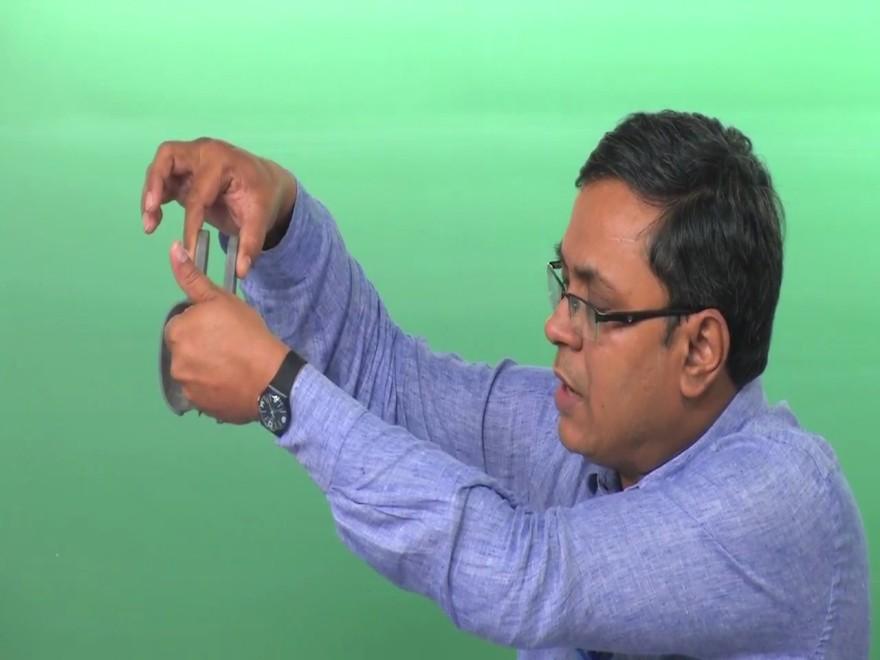
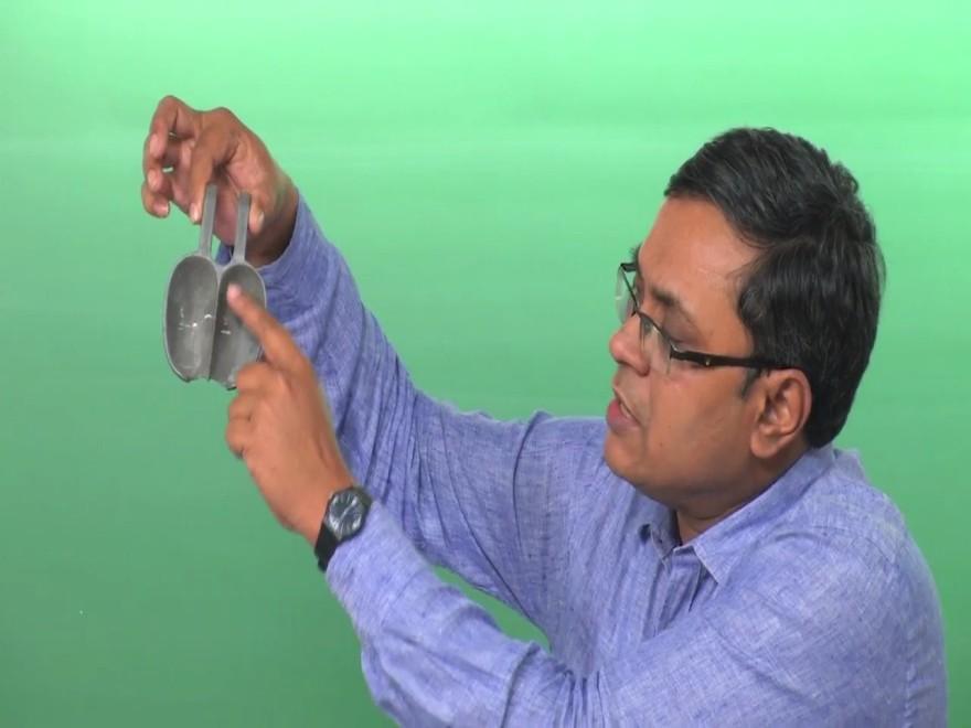
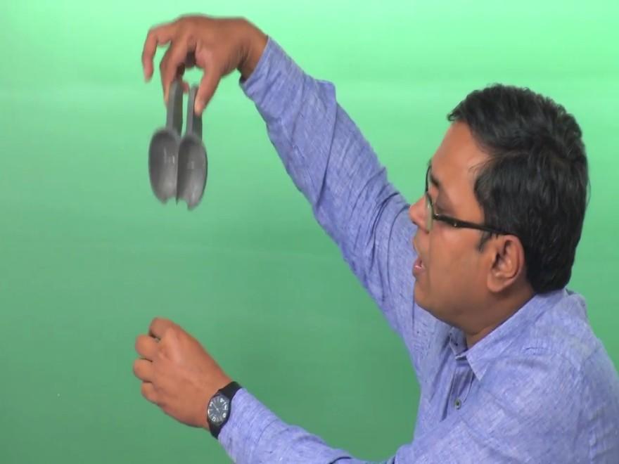
16 (Refer Slide Time: 24:40) The next or the most important component perhaps is this bucket. Now this bucket is shown, I will also show you a small model bucket which is not really used for power generation but it is more for classroom demonstrations and for demonstrations like I am going to do now. Let us look at these buckets first before we continue this discussion. (Refer Slide Time: 25:05)
17
18

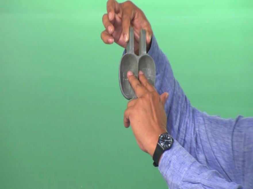
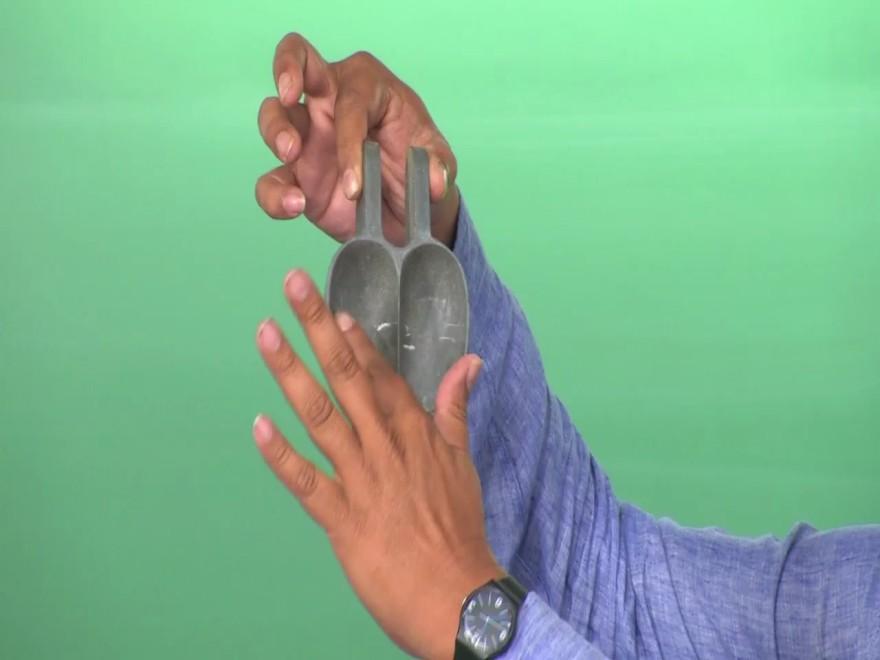
19 Imagine that this is my finger is the point where this bucket is fastened to the wheel and the water jet is coming and hitting the bucket, as a result the water comes here, this has a very sharp edge, you can see this very sharp edge, this is called the splitter edge. As the name suggests, this splits the jet into 2 halves, it goes here, one part of the jet comes out like this, the other part of the jet comes out like this. So as a result of the momentum change we get and from angular momentum conservation, we find the torque and this entire system will move. As this jet hits this bucket and the bucket moves, the next bucket comes from top because the wheel as I have shown you has multiple buckets. You can also find out how many buckets are required but that I will not discuss in today s lecture. So you see that as the bucket comes here, it hits, it goes and the next bucket comes and hits. It is done in such a way that we do not waste the water. So this is called the splitter edge and we have 2 cuplike structures which I will discuss with the PowerPoint slides, I am presenting a more detail now. So if you want to compare the picture that you see on the slide with this one, then it should be viewed in this fashion. You can see the view which is shown and I am taking a section XX as shown on the slide and let us look at this section XX in some more detail.

20 (Refer Slide Time: 27:00) So coming back to the slide we see that the bucket, the splitter edge is also visible now you can imagine a line joining here is the splitter edge and you are taking a section XX and viewing this section. You see that this is a splitter edge which is a very sharp one and as the name suggests, this splits water, I will show you some schematic of the water being split and this water will go and leave in this fashion. This beta 1 is the exit angle. So let us look at it slightly more carefully with the schematics. (Refer Slide Time: 27:37) So this is the same section which I showed you in the last slide and I have just taken the outline of it. This angle between the, which is tangent to these 2 curves is called the splitter
21 angle 2 beta S, beta S is a splitter angle and 2 beta S is the total splitter angle, because of symmetry it is 2 beta S. So waterjet comes from the right, it hits the splitter edge, it goes round the blade as I told you, as I showed you and then it comes out. So now think about the flow direction in the absence of any turbine blade, any Pelton turbine bucket. This is the flow direction, had there been no bucket, the flow would have continued undisturbed. Now because of the presence of the bucket the flow leaves at an angle beta 1 and hence there is a reflection Delta and you can see this Delta is very large, quite close to 180 degree. Let us digress from Pelton turbine and look back what you are studied in fluid dynamics portion of this course. You have done momentum conservation and you perhaps have also studied that you have plate which is C type, which is just imagine only this portion of the plate is there, it is not a Pelton turbine bucket, it is just a plate, then the flow comes here and leaves by 180 degree. Why we have that 180 degree, you have done the problems to show that it has a maximum momentum transfer and the maximum force. Now that maximum force will give rise to the maximum torque. So this kind of C structure for this blade is desirable when we are trying to generate a maximum force because of the change in direction. There is no change in pressure, I repeat, this is an impulse turbine, this bucket is in atmospheric condition, so there is no change in pressure. What causes this force is simply the direction change. And hence ideally it should have been 180 degree. Now in the real configuration 180 degree is not possible because as I told you that there is not just one bucket, there are many buckets which are arranged on the Pelton wheel. Now as one bucket is hit by the jet, it moves, the neighbouring bucket comes in. So if this deflected jet has to go back, it will hit the neighbouring jet which is not desirable. And hence we have a deflection angle Delta which is quite close to 180 degree but not 180 degree. Actually the value will be between 165 to 170 degrees. And the other angle is the splitter edge. When we have the splitter edge, we actually have typically between 7 degrees and 15 degrees. But many times we may solve the problem, many times we may do the first cut design assuming that these are actually not having any angle between the axis in the direction of the jet and the plates deviations. So we can say that if no information is given, if any problem you have to solve, then you can take beta S to be zero. So you understand but now you may say why do I need 2 of these C split structures, why do not we have a Pelton bucket

22 which is simpler to make with just one half because that itself gives me a large turning angle of Delta and I will get a large force? This is because we are also trying to balance the normal force. So you see that initially the jet is coming in the horizontal direction, when it leaves, it leaves with 2 components, one along horizontal, one along the normal. So that means if we are thinking in terms of forces, we will experience FX as well as FY. Now this force which is tangential is actually desirable because the tangential force gives rise to the torque, but the normal force is not desirable. And hence if we have a symmetric structure here, then it will balance or neutralise this Fx here by the Fx at the bottom. And hence we may not have any significant normal thrust. And this splitter actually ensures that the deviation or the flow is turning around in both directions properly. So this is why this structure however complicated it looks is very important and hence the bucket design is a very important part for the Pelton turbine design. Okay. Let us continue with the discussion further because we have to construct the velocity triangle. (Refer Slide Time: 32:42) The reason why I am trying to explain these things slowly is because unlike the Francis and Kaplan turbines which will talk in the next class, Pelton turbine is structurally slightly different. So let us start again with the water jet hitting the bucket and this is the pitch circle diameter as we have said, the direction of rotation is also given. So if we look at this portion more carefully, we can say that if we view it, this is the Pelton turbine bucket, this is the splitter edge and this water is jet is coming.

23 Essentially we are looking from this side and once it comes, if we construct a plane, then we can see that the water will come and leave like this. And that gives rise to these dotted lines. So now when I look at these dotted lines more carefully, I get the shape of the bucket and you see that U is the velocity, the rotational velocity, W2 and C2 are our usual definitions of relative velocity and absolute velocity respectively and we are talking about 2 as a subscript means this is the high pressure side, the inlet for these turbines. And we see that this is leaving, flow is leaving, this is W1 tangentially and of course U does not change, we are talking about U based on this diameter and this small height difference is negligible and hence let the U1 equal to U2 and we are talking about the absolute velocities. (Refer Slide Time: 34:22) So looking at the velocity triangles now more closely, we can bring the cartoon of the Pelton bucket and look at it at the pressure side as well as at the suction side. So our usual symbols of U, C2 and W2 is given. So if you see the flow comes like this and leaves, so the axe, angle between this axis and this direction is half of this 2 beta S or it is beta S. And hence from our definition of beta 2, this is nothing but 180 degree - beta S. So this has to be borne in mind. If in some problems or in some designs you do not want beta S, then beta 2 is 180 degree, that we will talk about later on. So right now we are talking about the generalised case. That is we have a beta S which is non-zero. Similarly we can talk about the exit or the outlet of the blade and the flow leaves tangentially which is given here by W1 and we have beta 1 and Alpha 1. And if there is no friction, since the pressure has to be, that, we get W 1 equal to W2. However friction may

24 also be present and in that case the friction will reduce the relative velocity and we have W ones K times W2 where K is less than one. So depending on what is given in the problem you may choose W1 equal to W2 but this specifically it is given that the friction is reducing the velocity and we have a factor of K, then that has to be accommodated. And in that case also please note that this relative velocity is, whether it is W 1 equal to W2 or W1 equal to K W2, the pressure is still atmospheric and there is no change in static pressure. So I repeat, if nothing is mentioned, choose frictionless flow, that is K equal to 1. Now we will talk about the specific work W BL and also the power. (Refer Slide Time: 36:31) So we say that come into specific work and power we can say that W BL is equal to U C2U C1U, why is that because U1 equal to U2 equal to U. And we can write C2U in terms of U W2U or U - W2 cos beta 2. Please keep the velocity triangle in mind. And we can further say from the exit velocity triangle that C1 U is nothing but U - W1 U which is U - W1 cos beta 1. And now we can relate W1 and W2, like W1 is K times W2 and we can take W2 out and we can write W BL equal to U W2 times - cos beta 2+ W1 is replaced as K times W W2 and hence K remains K times cos beta 1. Of course it is possible that we may have to do some simplifications and if we say that beta S is equal to 0, then what happens to beta 2, beta 2 is nothing but 180 degree and this triangle which you have seen at the inlet degenerates into a straight line. So we will have C2U and W2 all along one line and we say that W2 is nothing but C2 - U. I may also add here that this
25 C2 is nothing but the jet velocity which is CJ. The jet velocity that comes out of the nozzle, we assume that the same velocity reaches the Pelton turbine bucket and hence C2 equal to CJ. So we can say that in such a scenario where beta S is equal to 0, we get WBL equal to U times C2 - U times multiplied by 1+ K times cos beta 1 because cause beta 2 is equal to 1. And W2 has now been simply replaced as C2 - U. We can get from this relationship for the special case, I am writing now for the special case what is the power but you can do the same thing for the generalised case without any harm. So we can say that coupling power is rho V dot W BL which for the special case of beta S equal to 0 comes down to rho V dot U times C2 - U times 1+ K cos beta1. Now this result is interesting. We find that the power will be maximum when the jet velocity CJ or C2 is equal to twice U and the power will be 0 when CJ is equal to U. This is very important, why, because we are now talking about, see the first case is trivially true that when U equal to 0, that is the runner is not rotating, then there is no question of power generation. However, even if runner is rotating, you may end up in a scenario when there is no power, when does that happen, when C2 or CJ, that is the jet velocity is equal to the bucket speed. And this is called the runaway speed. What is runaway speed? In a simple English if I say runaway, that means something is running away. So imagine that the nozzle is human being, nozzle is sending jet of water and hitting the bucket and the bucket is also another human being, let us say you and your friend. Now when this, there is a gap between the nozzle exit and the bucket, now if the jet has a higher velocity, so even if the bucket is trying to run away, is trying to move away, it will hit the bucket. But when the limit comes, when the jet velocity is equal to the bucket rotational speed, then what happens, the bucket is not going to be hit, so there is no contact. So we are talking about the runaway speed and that is not desirable. So when there is no load, we are talking about the speed going to runaway speed and that brings us to the important question of how we can regulate the flow. So you understand we are talking about the power, this power will be maximum when the jet velocity is twice the rotational speed, you can do this calculation yourself and prove that what I am saying makes sense.

26 (Refer Slide Time: 41:26) And power will be zero is trivially true when U equal to 0 and when C 2 equal to U, this bracketed them goes to 0. Before I go into the regulation of Pelton turbine, let us talk about the need. Let us say we do not want the turbine to go for to the runaway speed and there is a scenario when there is no power extraction, so power is zero, it is tripped, so we have to somehow stop the turbine. You may say what is the problem, I will just bring the spear and block the nozzle. Even if I assume that you have a mechanism by which instantaneously you can bring the spear and block the nozzle, it is not desirable from the hydrodynamic point of view. You will end up getting what is known as a fluid transient phenomenon of water hammer. How do I visualize water hammer? Imagine that we all are fluid particles and in that fluid particles we are going from the penstock through the nozzle we are issuing out as a jet. And suddenly this spear comes and instantaneously block the nozzle exit. In that case what happens? I if I am a fluid particle, I will see that the suddenly the road is blocked but I want to escape, so then I will turn back and in this process the gap between the 2 fluid particles, let us say between you and me, it reduces. So there is a compression wave and then we try to escape from the other route, that is up the penstock. And then we find that we cannot go that path and then we reflect back. So this creates what is known as a compression and rarefaction waves and the fluid in this case the liquid actually behaves as a compressible flow. So this gives rise to a very high pressure in the piping system and the piping system gets damaged. So water hammer pressure or the fluid transient phenomenon called water hammer
27 has to be avoided. And hence even if it is possible theoretical into during the spear and block the water instantaneously, it is not desirable. So what we can do alternately? We can say that we can bring a deflector, this deflector in a normal position is open which allows the jet to go unhindered and hit the bucket. When it is required, when we want to stop the turbine, 2 things can be done, one is we can use the brake nozzle, do you remember the brake nozzle? We talked about the brake nozzle which actually acts on the opposite side of the bucket and tries to slowdown. So we can engage the brake nozzles when we are trying to slowdown the turbine and simultaneously engage this deflector. As the name suggests the deflector actually deflects the fluid. And when it deflects the fluid, the jet comes out of the nozzle, very true but it does not go straight and hit the bucket, it gets reflected and falls. And then we have enough time to bring the spear slowly and close it, so that water hammer pressure does not take place. And hence the regulation of Pelton turbine is done when we are talking about the flow regulation. This brings us to an end of this discussion on Pelton turbine, of course we will take up some problems when we do the tutorials to do get the mathematics correctly. (Refer Slide Time: 45:12) So now we to summarise that we have talked about the definition of net head, we have also talked about the classifications of the turbines based on different yardsticks direction of flow, impulse reaction but most importantly based on the specific speed. We have talked about the structure and components of Pelton turbine and we have also talked about the flow regulation
28 which is required. With this I conclude the discussion on Pelton turbine, we will continue the discussion on hydraulic turbine in the next lecture when we talk about the reaction turbines, namely Francis and Kaplan turbine. And there we will also introduce the concept of the structure called draft tube. Thank you.
Introduction to Fluid Machines and Compressible Flow Prof. S. K. Som Department of Mechanical Engineering Indian Institute of Technology, Kharagpur
 Introduction to Fluid Machines and Compressible Flow Prof. S. K. Som Department of Mechanical Engineering Indian Institute of Technology, Kharagpur Lecture - 1 Introduction to Fluid Machines Well, good
Introduction to Fluid Machines and Compressible Flow Prof. S. K. Som Department of Mechanical Engineering Indian Institute of Technology, Kharagpur
 Introduction to Fluid Machines and Compressible Flow Prof. S. K. Som Department of Mechanical Engineering Indian Institute of Technology, Kharagpur Lecture - 07 Analysis of Force on the Bucket of Pelton
Introduction to Fluid Machines and Compressible Flow Prof. S. K. Som Department of Mechanical Engineering Indian Institute of Technology, Kharagpur
 Introduction to Fluid Machines and Compressible Flow Prof. S. K. Som Department of Mechanical Engineering Indian Institute of Technology, Kharagpur Lecture - 8 Specific Speed, Governing and Limitation
(Refer Slide Time: 0:57)
") Fluid Dynamics And Turbo Machines. Professor Dr Dhiman Chatterjee. Department Of Mechanical Engineering. Indian Institute Of Technology Madras. Part B. Module-2. Lecture-4. Representation of Turbo Machines
Fluid Dynamics And Turbo Machines. Professor Dr Dhiman Chatterjee. Department Of Mechanical Engineering. Indian Institute Of Technology Madras. Part B. Module-2. Lecture-4. Representation of Turbo Machines
Introduction to Fluid Machines and Compressible Flow Prof. S.K Som Department of Mechanical Engineering Indian Institute of Technology, Kharagpur
 Introduction to Fluid Machines and Compressible Flow Prof. S.K Som Department of Mechanical Engineering Indian Institute of Technology, Kharagpur Lecture No. # 24 Axial Flow Compressor Part I Good morning
HYDRAULIC TURBINES. Hydraulics and Hydraulic Machines
 HYDRAULIC TURBINES Introduction: The device which converts h ydraulic energy into mechanical energy or vice versa is known as Hydraulic Machines. The h ydraulic machines which convert h ydraulic energy
Introduction to Fluid Machines, and Compressible Flow Prof. S. K. Som Department of Mechanical Engineering Indian Institute of Technology, Kharagpur
 Introduction to Fluid Machines, and Compressible Flow Prof. S. K. Som Department of Mechanical Engineering Indian Institute of Technology, Kharagpur Lecture - 09 Introduction to Reaction Type of Hydraulic
(Refer Slide Time: 0:45)
") (Refer Slide Time: 0:45) Fluid Machines. Professor Sankar Kumar Som. Department Of Mechanical Engineering. Indian Institute Of Technology Kharagpur. Lecture-3. Impulse and Reaction Machines: Introductory
(Refer Slide Time: 0:45) Fluid Machines. Professor Sankar Kumar Som. Department Of Mechanical Engineering. Indian Institute Of Technology Kharagpur. Lecture-3. Impulse and Reaction Machines: Introductory
(Refer Slide Time: 4:41)
") Fluid Machines. Professor Sankar Kumar Som. Department Of Mechanical Engineering. Indian Institute Of Technology Kharagpur. Lecture-30. Basic Principle and Energy Transfer in Centrifugal Compressor Part
Fluid Machines. Professor Sankar Kumar Som. Department Of Mechanical Engineering. Indian Institute Of Technology Kharagpur. Lecture-30. Basic Principle and Energy Transfer in Centrifugal Compressor Part
Introduction to Fluid Machines and Compressible Flow Prof. S. K. Som Department of Mechanical Engineering Indian Institute of Technology, Kharagpur
 Introduction to Fluid Machines and Compressible Flow Prof. S. K. Som Department of Mechanical Engineering Indian Institute of Technology, Kharagpur Lecture - 21 Centrifugal Compressor Part I Good morning
mywbut.com Hydraulic Turbines
 Hydraulic Turbines Hydro-electric power accounts for up to 0% of the world s electrical generation. Hydraulic turbines come in a variety of shapes determined by the available head and a number of sizes
nozzle which is fitted to a pipe through which the liquid is flowing under pressure.
 Impact of Jets 1. The liquid comes out in the form of a jet from the outlet of a nozzle which is fitted to a pipe through which the liquid is flowing under pressure. The following cases of the impact of
Turbomachinery Aerodynamics Prof. Bhaskar Roy Prof. A M Pradeep Department of Aerospace Engineering Indian Institute of Technology, Bombay
 Turbomachinery Aerodynamics Prof. Bhaskar Roy Prof. A M Pradeep Department of Aerospace Engineering Indian Institute of Technology, Bombay Lecture No. # 26 Tutorial 4: 3D Flows in Axial Flow Turbines We
ME 316: Thermofluids Laboratory
 ME 316 Thermofluid Laboratory 6.1 KING FAHD UNIVERSITY OF PETROLEUM & MINERALS ME 316: Thermofluids Laboratory PELTON IMPULSE TURBINE 1) OBJECTIVES a) To introduce the operational principle of an impulse
Hydraulics Prof. Dr. Arup Kumar Sarma Department of Civil Engineering Indian Institute of Technology, Guwahati
 Hydraulics Prof. Dr. Arup Kumar Sarma Department of Civil Engineering Indian Institute of Technology, Guwahati Module No. # 08 Pipe Flow Lecture No. # 05 Water Hammer and Surge Tank Energy cannot be consumed
To investigate the performance of the Pelton Wheel turbine with different range of flow rates and rotational speeds.
 Experiment No. 1 PELTON WHEEL TURBINE Objective To investigate the performance of the Pelton Wheel turbine with different range of flow rates and rotational speeds. Summary of theory Pelton Wheel turbine
Hydraulics Prof. Dr. Arup Kumar Sarma Department of Civil Engineering Indian Institute of Technology, Guwahati
 Hydraulics Prof. Dr. Arup Kumar Sarma Department of Civil Engineering Indian Institute of Technology, Guwahati Module No. # 04 Gradually Varied Flow Lecture No. # 07 Rapidly Varied Flow: Hydraulic Jump
Chapter Four fluid flow mass, energy, Bernoulli and momentum
 4-1Conservation of Mass Principle Consider a control volume of arbitrary shape, as shown in Fig (4-1). Figure (4-1): the differential control volume and differential control volume (Total mass entering
Jet Aircraft Propulsion Prof. Bhaskar Roy Prof. A M Pradeep Department of Aerospace Engineering Indian Institute of Technology, Bombay
 Jet Aircraft Propulsion Prof. Bhaskar Roy Prof. A M Pradeep Department of Aerospace Engineering Indian Institute of Technology, Bombay Lecture No. #03 Jet Engine Basic Performance Parameters We are talking
Introduction to Fluid Machines (Lectures 49 to 53)
") Introduction to Fluid Machines (Lectures 49 to 5) Q. Choose the crect answer (i) (ii) (iii) (iv) A hydraulic turbine rotates at N rpm operating under a net head H and having a discharge Q while developing
Introduction to Fluid Machines (Lectures 49 to 5) Q. Choose the crect answer (i) (ii) (iii) (iv) A hydraulic turbine rotates at N rpm operating under a net head H and having a discharge Q while developing
Steam and Gas Power Systems Prof. Ravi Kumar Department of Mechanical industrial engineering Indian Institute of Technology Roorkee
 Steam and Gas Power Systems Prof. Ravi Kumar Department of Mechanical industrial engineering Indian Institute of Technology Roorkee Module No # 06 Lecture No # 26 Impulse Reaction Steam Turbines Hello
(Refer Slide Time: 2:14)
") Fluid Dynamics And Turbo Machines. Professor Dr Shamit Bakshi. Department Of Mechanical Engineering. Indian Institute Of Technology Madras. Part A. Module-1. Lecture-3. Introduction To Fluid Flow. (Refer
Fluid Dynamics And Turbo Machines. Professor Dr Shamit Bakshi. Department Of Mechanical Engineering. Indian Institute Of Technology Madras. Part A. Module-1. Lecture-3. Introduction To Fluid Flow. (Refer
where = rate of change of total energy of the system, = rate of heat added to the system, = rate of work done by the system
 The Energy Equation for Control Volumes Recall, the First Law of Thermodynamics: where = rate of change of total energy of the system, = rate of heat added to the system, = rate of work done by the system
Basic Thermodynamics Prof. S.K Som Department of Mechanical Engineering Indian Institute of Technology, Kharagpur
 Basic Thermodynamics Prof. S.K Som Department of Mechanical Engineering Indian Institute of Technology, Kharagpur Lecture - 17 Properties of Pure Substances-I Good morning to all of you. We were discussing
Jet Aircraft Propulsion Prof. Bhaskar Roy Prof A M Pradeep Department of Aerospace Engineering Indian Institute of Technology, Bombay
 Jet Aircraft Propulsion Prof. Bhaskar Roy Prof A M Pradeep Department of Aerospace Engineering Indian Institute of Technology, Bombay Module No. #01 Lecture No. # 07 Jet Engine Cycles For Aircraft propulsion
SUMMER 14 EXAMINATION
 Important Instructions to examiners: 1) The answers should be examined by key words and not as word-to-word as given in the model answer scheme. 2) The model answer and the answer written by candidate
Applied Thermodynamics for Marine Systems Prof. P. K. Das Department of Mechanical Engineering Indian Institute of Technology, Kharagpur
 Applied Thermodynamics for Marine Systems Prof. P. K. Das Department of Mechanical Engineering Indian Institute of Technology, Kharagpur Lecture 2 First Law of Thermodynamics (Closed System) In the last
Dynamics of Machines Prof. Amitabha Ghosh Department of Mechanical Engineering Indian Institute of Technology, Kanpur
 Dynamics of Machines Prof. Amitabha Ghosh Department of Mechanical Engineering Indian Institute of Technology, Kanpur Module - 3 Lecture - 3 Balancing Machines and Field Balancing of Rotating Discs We
Jet Aircraft Propulsion Prof. Bhaskar Roy Prof. A.M. Pradeep Department of Aerospace Engineering
 Jet Aircraft Propulsion Prof. Bhaskar Roy Prof. A.M. Pradeep Department of Aerospace Engineering Indian Institute of Technology, IIT Bombay Module No. # 01 Lecture No. # 08 Cycle Components and Component
SOE2156: Fluids Lecture 4
 Turbo SOE2156: s Lecture 4 machine { a device exchanging energy (work) between a uid and a mechanical system. In particular : a turbomachine is a device using a rotating mechanical system. The ow of energy
Heat and Mass Transfer Prof. S.P. Sukhatme Department of Mechanical Engineering Indian Institute of Technology, Bombay
 Heat and Mass Transfer Prof. S.P. Sukhatme Department of Mechanical Engineering Indian Institute of Technology, Bombay Lecture No. 18 Forced Convection-1 Welcome. We now begin our study of forced convection
Advanced Hydrology Prof. Dr. Ashu Jain Department of Civil Engineering Indian Institute of Technology, Kanpur. Lecture 6
 Advanced Hydrology Prof. Dr. Ashu Jain Department of Civil Engineering Indian Institute of Technology, Kanpur Lecture 6 Good morning and welcome to the next lecture of this video course on Advanced Hydrology.
Conservation of Momentum using Control Volumes
 Conservation of Momentum using Control Volumes Conservation of Linear Momentum Recall the conservation of linear momentum law for a system: In order to convert this for use in a control volume, use RTT
Surveying Prof. Bharat Lohani Indian Institute of Technology, Kanpur. Module 5 Lecture 1
 Surveying Prof. Bharat Lohani Indian Institute of Technology, Kanpur (Refer Slide Time: 00:20) Module 5 Lecture 1 Welcome to this another lecture on basic surveying. Today we are going to start a new module.
Steam and Gas Power Systems Prof. Ravi Kumar Department Of Mechanical and Industrial Engineering Indian Institute of Technology - Roorkee
 Steam and Gas Power Systems Prof. Ravi Kumar Department Of Mechanical and Industrial Engineering Indian Institute of Technology - Roorkee Module No # 05 Lecture No # 23 Impulse Steam Turbine Hello I welcome
Antennas Prof. Girish Kumar Department of Electrical Engineering Indian Institute of Technology, Bombay. Module 02 Lecture 08 Dipole Antennas-I
 Antennas Prof. Girish Kumar Department of Electrical Engineering Indian Institute of Technology, Bombay Module 02 Lecture 08 Dipole Antennas-I Hello, and welcome to today s lecture. Now in the last lecture
Dr. S. Ramachandran Prof. R. Devaraj. Mr. YVS. Karthick AIR WALK PUBLICATIONS
 Fluid Machinery As per Revised Syllabus of Leading Universities including APJ ABDUL KALAM TECHNOLOGICAL UNIVERSITY Dr. S. Ramachandran Prof. R. Devaraj Professors School of Mechanical Engineering Sathyabama
(Refer Slide Time: 00:00:43 min) Welcome back in the last few lectures we discussed compression refrigeration systems.
 Welcome back in the last few lectures we discussed compression refrigeration systems.") Refrigeration and Air Conditioning Prof. M. Ramgopal Department of Mechanical Engineering Indian Institute of Technology, Kharagpur Lecture No. # 14 Vapour Absorption Refrigeration Systems (Refer Slide
Refrigeration and Air Conditioning Prof. M. Ramgopal Department of Mechanical Engineering Indian Institute of Technology, Kharagpur Lecture No. # 14 Vapour Absorption Refrigeration Systems (Refer Slide
Fluid Mechanics Prof. S.K. Som Department of Mechanical Engineering Indian Institute of Technology, Kharagpur
 Fluid Mechanics Prof. S.K. Som Department of Mechanical Engineering Indian Institute of Technology, Kharagpur Lecture - 42 Flows with a Free Surface Part II Good morning. I welcome you to this session
In this lecture... Radial flow turbines Types of radial flow turbines Thermodynamics and aerodynamics Losses in radial flow turbines
 Lect- 35 1 In this lecture... Radial flow turbines Types of radial flow turbines Thermodynamics and aerodynamics Losses in radial flow turbines Radial turbines Lect-35 Development of radial flow turbines
Industrial Instrumentation Prof. A. Barua Department of Electrical Engineering Indian Institute of Technology Kharagpur. Lecture - 14 Flowmeter ΙΙΙ
 Industrial Instrumentation Prof. A. Barua Department of Electrical Engineering Indian Institute of Technology Kharagpur Lecture - 14 Flowmeter ΙΙΙ Welcome to lesson 14 of Industrial Instrumentation. In
Dynamics of Machines. Prof. Amitabha Ghosh. Department of Mechanical Engineering. Indian Institute of Technology, Kanpur. Module No.
 Dynamics of Machines Prof. Amitabha Ghosh Department of Mechanical Engineering Indian Institute of Technology, Kanpur Module No. # 07 Lecture No. # 01 In our previous lectures, you have noticed that we
Contents. 2 Basic Components Aerofoils Force Generation Performance Parameters xvii
 Contents 1 Working Principles... 1 1.1 Definition of a Turbomachine... 1 1.2 Examples of Axial Turbomachines... 2 1.2.1 Axial Hydraulic Turbine... 2 1.2.2 Axial Pump... 4 1.3 Mean Line Analysis... 5 1.4
Mechanics, Heat, Oscillations and Waves Prof. V. Balakrishnan Department of Physics Indian Institute of Technology, Madras
 Mechanics, Heat, Oscillations and Waves Prof. V. Balakrishnan Department of Physics Indian Institute of Technology, Madras Lecture - 21 Central Potential and Central Force Ready now to take up the idea
EXPERIMENT No.1 FLOW MEASUREMENT BY ORIFICEMETER
 EXPERIMENT No.1 FLOW MEASUREMENT BY ORIFICEMETER 1.1 AIM: To determine the co-efficient of discharge of the orifice meter 1.2 EQUIPMENTS REQUIRED: Orifice meter test rig, Stopwatch 1.3 PREPARATION 1.3.1
Objectives. Conservation of mass principle: Mass Equation The Bernoulli equation Conservation of energy principle: Energy equation
 Objectives Conservation of mass principle: Mass Equation The Bernoulli equation Conservation of energy principle: Energy equation Conservation of Mass Conservation of Mass Mass, like energy, is a conserved
Engineering Mechanics Prof. U. S. Dixit Department of Mechanical Engineering Indian Institute of Technology, Guwahati
 Engineering Mechanics Prof. U. S. Dixit Department of Mechanical Engineering Indian Institute of Technology, Guwahati Module No. - 01 Basics of Statics Lecture No. - 01 Fundamental of Engineering Mechanics
Fluid Mechanics Prof. S. K. Som Department of Mechanical Engineering Indian Institute of Technology, Kharagpur
 Fluid Mechanics Prof. S. K. Som Department of Mechanical Engineering Indian Institute of Technology, Kharagpur Lecture - 15 Conservation Equations in Fluid Flow Part III Good afternoon. I welcome you all
the pitot static measurement equal to a constant C which is to take into account the effect of viscosity and so on.
 Mechanical Measurements and Metrology Prof. S. P. Venkateshan Department of Mechanical Engineering Indian Institute of Technology, Madras Module -2 Lecture - 27 Measurement of Fluid Velocity We have been
Applied Thermodynamics for Marine Systems Prof. P. K. Das Department of Mechanical Engineering Indian Institute of Technology, Kharagpur
 Applied Thermodynamics for Marine Systems Prof. P. K. Das Department of Mechanical Engineering Indian Institute of Technology, Kharagpur Lecture No - 03 First Law of Thermodynamics (Open System) Good afternoon,
Chemical Reaction Engineering Prof. Jayant Modak Department of Chemical Engineering Indian Institute of Science, Bangalore
 Chemical Reaction Engineering Prof. Jayant Modak Department of Chemical Engineering Indian Institute of Science, Bangalore Lecture No. # 26 Problem solving : Heterogeneous reactions Friends, in last few
Foundation Engineering Dr. Priti Maheshwari Department Of Civil Engineering Indian Institute Of Technology, Roorkee
 Foundation Engineering Dr. Priti Maheshwari Department Of Civil Engineering Indian Institute Of Technology, Roorkee Module - 02 Lecture - 15 Machine Foundations - 3 Hello viewers, In the last class we
Process Control and Instrumentation Prof. D. Sarkar Department of Chemical Engineering Indian Institute of Technology, Kharagpur
 Process Control and Instrumentation Prof. D. Sarkar Department of Chemical Engineering Indian Institute of Technology, Kharagpur Lecture - 35 Instrumentation: General Principles of Measurement Systems
Hydraulic Turbines. Table 6.1 Parameters of hydraulic turbines. Power P (kw) Speed N (rpm)
 Speed N (rpm)") 6 Hydraulic Turbines Problem 1 There are 10 solved examples and 7 exercise problems (exclude Problems 1, 2, and 10) in this chapter. Prepare a table to mention the values of all the parameters, such as
6 Hydraulic Turbines Problem 1 There are 10 solved examples and 7 exercise problems (exclude Problems 1, 2, and 10) in this chapter. Prepare a table to mention the values of all the parameters, such as
Introduction to Turbomachinery
 1. Coordinate System Introduction to Turbomachinery Since there are stationary and rotating blades in turbomachines, they tend to form a cylindrical form, represented in three directions; 1. Axial 2. Radial
CIVE HYDRAULIC ENGINEERING PART II Pierre Julien Colorado State University
 1 CIVE 401 - HYDRAULIC ENGINEERING PART II Pierre Julien Colorado State University Problems with and are considered moderate and those with are the longest and most difficult. In 2018 solve the problems
Rocket Propulsion Prof. K. Ramamurthi Department of Mechanical Engineering Indian Institute of Technology, Madras
 Rocket Propulsion Prof. K. Ramamurthi Department of Mechanical Engineering Indian Institute of Technology, Madras Lecture 11 Area Ratio of Nozzles: Under Expansion and Over Expansion (Refer Slide Time:
ME332 FLUID MECHANICS LABORATORY (PART II)
") ME332 FLUID MECHANICS LABORATORY (PART II) Mihir Sen Department of Aerospace and Mechanical Engineering University of Notre Dame Notre Dame, IN 46556 Version: April 2, 2002 Contents Unit 5: Momentum transfer
ME332 FLUID MECHANICS LABORATORY (PART II) Mihir Sen Department of Aerospace and Mechanical Engineering University of Notre Dame Notre Dame, IN 46556 Version: April 2, 2002 Contents Unit 5: Momentum transfer
Rocket propulsion Prof. K. Ramamurthi Department of Mechanical Engineering Indian Institute of Technology, Madras. Lecture 09 Theory of Nozzles
 Rocket propulsion Prof. K. Ramamurthi Department of Mechanical Engineering Indian Institute of Technology, Madras Lecture 09 Theory of Nozzles (Refer Slide Time: 00:14) Good morning. We will develop the
COURSE NUMBER: ME 321 Fluid Mechanics I 3 credit hour. Basic Equations in fluid Dynamics
 COURSE NUMBER: ME 321 Fluid Mechanics I 3 credit hour Basic Equations in fluid Dynamics Course teacher Dr. M. Mahbubur Razzaque Professor Department of Mechanical Engineering BUET 1 Description of Fluid
Fluid Mechanics Prof. S. K. Som Department of Mechanical Engineering Indian Institute of Technology, Kharagpur. Lecture - 9 Fluid Statics Part VI
 Fluid Mechanics Prof. S. K. Som Department of Mechanical Engineering Indian Institute of Technology, Kharagpur Lecture - 9 Fluid Statics Part VI Good morning, I welcome you all to this session of Fluid
Mechanical Measurements and Metrology Prof. S. P. Venkateshan Department of Mechanical Engineering Indian Institute of Technology, Madras
 Mechanical Measurements and Metrology Prof. S. P. Venkateshan Department of Mechanical Engineering Indian Institute of Technology, Madras Module - 3 Lecture - 33 Measurement of Volume and Mass Flow Rate
Digital Signal Processing Prof. T. K. Basu Department of Electrical Engineering Indian Institute of Technology, Kharagpur
 Digital Signal Processing Prof. T. K. Basu Department of Electrical Engineering Indian Institute of Technology, Kharagpur Lecture - 6 Z-Transform (Contd.) Discussing about inverse inverse Z transform,
Dynamics of Ocean Structures Prof. Dr. Srinivasan Chandrasekaran Department of Ocean Engineering Indian Institute of Technology, Madras
 Dynamics of Ocean Structures Prof. Dr. Srinivasan Chandrasekaran Department of Ocean Engineering Indian Institute of Technology, Madras Module - 1 Lecture - 13 Undamped and Damped Systems II (Refer Slide
Lecture - 2A Instruments-I
 Engineering Metrology Prof. J. Ramkumar Department of Mechanical Engineering & Design Programme Indian Institute of Technology, Kanpur Dr. Amandeep Singh Oberoi Department of Industrial & Production Engineering
Chemical Reaction Engineering Prof. Jayant Modak Department of Chemical Engineering Indian Institute of Science, Bangalore
 Chemical Reaction Engineering Prof. Jayant Modak Department of Chemical Engineering Indian Institute of Science, Bangalore Lecture No. #40 Problem solving: Reactor Design Friends, this is our last session
Plasma Physics Prof. V. K. Tripathi Department of Physics Indian Institute of Technology, Delhi
 Plasma Physics Prof. V. K. Tripathi Department of Physics Indian Institute of Technology, Delhi Module No. # 01 Lecture No. # 22 Adiabatic Invariance of Magnetic Moment and Mirror Confinement Today, we
Conduction and Radiation Prof. C. Balaji Department of Mechanical Engineering Indian Institute of Technology, Madras
 Conduction and Radiation Prof. C. Balaji Department of Mechanical Engineering Indian Institute of Technology, Madras Module No. # 01 Lecture No. # 16 Reflectivity We will continue with our discussion on
vector H. If O is the point about which moments are desired, the angular moment about O is given:
 The angular momentum A control volume analysis can be applied to the angular momentum, by letting B equal to angularmomentum vector H. If O is the point about which moments are desired, the angular moment
Theory & Practice of Rotor Dynamics Prof. Rajiv Tiwari Department of Mechanical Engineering Indian Institute of Technology Guwahati
 Theory & Practice of Rotor Dynamics Prof. Rajiv Tiwari Department of Mechanical Engineering Indian Institute of Technology Guwahati Module - 8 Balancing Lecture - 1 Introduce To Rigid Rotor Balancing Till
Power System Analysis Prof. A. K. Sinha Department of Electrical Engineering Indian Institute of Technology, Kharagpur
 Power System Analysis Prof. A. K. Sinha Department of Electrical Engineering Indian Institute of Technology, Kharagpur Lecture - 9 Transmission Line Steady State Operation Welcome to lesson 9, in Power
Electromagnetic Theory Prof. D. K. Ghosh Department of Physics Indian Institute of Technology, Bombay
 Electromagnetic Theory Prof. D. K. Ghosh Department of Physics Indian Institute of Technology, Bombay Lecture -1 Element of vector calculus: Scalar Field and its Gradient This is going to be about one
For example an empty bucket weighs 2.0kg. After 7 seconds of collecting water the bucket weighs 8.0kg, then:
 Hydraulic Coefficient & Flow Measurements ELEMENTARY HYDRAULICS National Certificate in Technology (Civil Engineering) Chapter 3 1. Mass flow rate If we want to measure the rate at which water is flowing
MASS, MOMENTUM, AND ENERGY EQUATIONS
 MASS, MOMENTUM, AND ENERGY EQUATIONS This chapter deals with four equations commonly used in fluid mechanics: the mass, Bernoulli, Momentum and energy equations. The mass equation is an expression of the
ScienceDirect Abstract
 Available online at www.sciencedirect.com ScienceDirect Procedia Engineering 70 ( 2014 ) 1539 1548 12th International Conference on Computing and Control for the Water Industry, CCWI2013 Cross-Flow turbine
Special Theory of Relativity Prof. Shiva Prasad Department of Physics Indian Institute of Technology, Bombay. Lecture - 15 Momentum Energy Four Vector
 Special Theory of Relativity Prof. Shiva Prasad Department of Physics Indian Institute of Technology, Bombay Lecture - 15 Momentum Energy Four Vector We had started discussing the concept of four vectors.
(Refer Slide Time 1:25)
") Mechanical Measurements and Metrology Prof. S. P. Venkateshan Department of Mechanical Engineering Indian Institute of Technology, Madras Module - 2 Lecture - 24 Transient Response of Pressure Transducers
Mechanical Measurements and Metrology Prof. S. P. Venkateshan Department of Mechanical Engineering Indian Institute of Technology, Madras Module - 2 Lecture - 24 Transient Response of Pressure Transducers
Advanced Chemical Reaction Engineering Prof. H. S. Shankar Department of Chemical Engineering IIT Bombay. Lecture - 03 Design Equations-1
 (Refer Slide Time: 00:19) Advanced Chemical Reaction Engineering Prof. H. S. Shankar Department of Chemical Engineering IIT Bombay Lecture - 03 Design Equations-1 We are looking at advanced reaction engineering;
Hydrostatics and Stability Dr. Hari V Warrior Department of Ocean Engineering and Naval Architecture Indian Institute of Technology, Kharagpur
 Hydrostatics and Stability Dr. Hari V Warrior Department of Ocean Engineering and Naval Architecture Indian Institute of Technology, Kharagpur Module No. # 01 Lecture No. # 09 Free Surface Effect In the
Department of Civil and Environmental Engineering CVNG 1001: Mechanics of Fluids
 INTRODUCTION Hydrodynamic Machines A hydromachine is a device used either for extracting energy from a fluid or to add energy to a fluid. There are many types of hydromachines and Figure 1 below illustrates
INSTITUTE OF AERONAUTICAL ENGINEERING
 LECTURE NOTES ON Hydraulics and Hydraulic Machines Department of Civil Engineering INSTITUTE OF AERONAUTICAL ENGINEERING Dundigal 500 043, Hyderabad mechanis m COURTESY IARE Governors for Turbines Pendulum
Surveying Prof. Bharat Lohani Department of Civil Engineering Indian Institute of Technology, Kanpur. Module - 3 Lecture - 4 Linear Measurements
 Surveying Prof. Bharat Lohani Department of Civil Engineering Indian Institute of Technology, Kanpur Module - 3 Lecture - 4 Linear Measurements Welcome again to this another video lecture on basic surveying.
(Refer Slide Time: 0:23)
") (Refer Slide Time: 0:23) Engineering Thermodynamics Professor Jayant K Singh Department of Chemical Engineering Indian Institute of Technology Kanpur Lecture 06 First Law of Thermodynamic and Energy Balance
(Refer Slide Time: 0:23) Engineering Thermodynamics Professor Jayant K Singh Department of Chemical Engineering Indian Institute of Technology Kanpur Lecture 06 First Law of Thermodynamic and Energy Balance
Basic Thermodynamics Prof. S.K. Som Department of Mechanical Engineering Indian Institute of Technology, Kharagpur
 Basic Thermodynamics Prof. S.K. Som Department of Mechanical Engineering Indian Institute of Technology, Kharagpur Lecture 12 Second Law and Available Energy III Good morning. I welcome you to this session.
Gas Dynamics and Propulsion Dr. Babu Viswanathan Department of Mechanical Engineering Indian Institute of Technology - Madras. Lecture 01 Introduction
 Gas Dynamics and Propulsion Dr. Babu Viswanathan Department of Mechanical Engineering Indian Institute of Technology - Madras Lecture 01 Introduction Good morning. I will start our lecture today with brief
Fluid Mechanics Prof. T.I. Eldho Department of Civil Engineering Indian Institute of Technology, Bombay. Lecture - 17 Laminar and Turbulent flows
 Fluid Mechanics Prof. T.I. Eldho Department of Civil Engineering Indian Institute of Technology, Bombay Lecture - 17 Laminar and Turbulent flows Welcome back to the video course on fluid mechanics. In
Basic Thermodynamics. Prof. S. K. Som. Department of Mechanical Engineering. Indian Institute of Technology, Kharagpur.
 Basic Thermodynamics Prof. S. K. Som Department of Mechanical Engineering Indian Institute of Technology, Kharagpur Lecture - 06 Second Law and its Corollaries I Good afternoon, I welcome you all to this
Consider a control volume in the form of a straight section of a streamtube ABCD.
 6 MOMENTUM EQUATION 6.1 Momentum and Fluid Flow In mechanics, the momentum of a particle or object is defined as the product of its mass m and its velocity v: Momentum = mv The particles of a fluid stream
Experiment (4): Flow measurement
: Flow measurement") Experiment (4): Flow measurement Introduction: The flow measuring apparatus is used to familiarize the students with typical methods of flow measurement of an incompressible fluid and, at the same time
Experiment (4): Flow measurement Introduction: The flow measuring apparatus is used to familiarize the students with typical methods of flow measurement of an incompressible fluid and, at the same time
Surveying Prof. Bharat Lohani Department of Civil Engineering Indian Institute of Technology, Kanpur. Module - 4 Lecture - 1 Compass Surveying
 Surveying Prof. Bharat Lohani Department of Civil Engineering Indian Institute of Technology, Kanpur Module - 4 Lecture - 1 Compass Surveying Welcome to this video lecture series on basic surveying and
Mechanical Vibrations Prof. Rajiv Tiwari Department of Mechanical Engineering Indian Institute of Technology, Guwahati
 Mechanical Vibrations Prof. Rajiv Tiwari Department of Mechanical Engineering Indian Institute of Technology, Guwahati Module - 12 Signature analysis and preventive maintenance Lecture - 3 Field balancing
Applied Fluid Mechanics
 Applied Fluid Mechanics 1. The Nature of Fluid and the Study of Fluid Mechanics 2. Viscosity of Fluid 3. Pressure Measurement 4. Forces Due to Static Fluid 5. Buoyancy and Stability 6. Flow of Fluid and
MITOCW ocw-18_02-f07-lec17_220k
 MITOCW ocw-18_02-f07-lec17_220k The following content is provided under a Creative Commons license. Your support will help MIT OpenCourseWare continue to offer high quality educational resources for free.
Mathematics-I Prof. S.K. Ray Department of Mathematics and Statistics Indian Institute of Technology, Kanpur. Lecture 1 Real Numbers
 Mathematics-I Prof. S.K. Ray Department of Mathematics and Statistics Indian Institute of Technology, Kanpur Lecture 1 Real Numbers In these lectures, we are going to study a branch of mathematics called
MITOCW watch?v=pqkyqu11eta
 MITOCW watch?v=pqkyqu11eta The following content is provided under a Creative Commons license. Your support will help MIT OpenCourseWare continue to offer high quality educational resources for free. To
Circuits for Analog System Design Prof. Gunashekaran M K Center for Electronics Design and Technology Indian Institute of Science, Bangalore
 Circuits for Analog System Design Prof. Gunashekaran M K Center for Electronics Design and Technology Indian Institute of Science, Bangalore Lecture No. # 08 Temperature Indicator Design Using Op-amp Today,
(Refer Slide Time: 1: 19)
") Mechanical Measurements and Metrology Prof. S. P. Venkateshan Department of Mechanical Engineering Indian Institute of Technology, Madras Module - 4 Lecture - 46 Force Measurement So this will be lecture
Mechanical Measurements and Metrology Prof. S. P. Venkateshan Department of Mechanical Engineering Indian Institute of Technology, Madras Module - 4 Lecture - 46 Force Measurement So this will be lecture
Physics I : Oscillations and Waves Prof. S. Bharadwaj Department of Physics and Meteorology Indian Institute of Technology, Kharagpur
 Physics I : Oscillations and Waves Prof. S. Bharadwaj Department of Physics and Meteorology Indian Institute of Technology, Kharagpur Lecture - 21 Diffraction-II Good morning. In the last class, we had
Lecture on Francis Turbine. by Dr. Shibayan Sarkar Department of Mechanical Engg Indian Institute of Technology (ISM), Dhanbad
, Dhanbad") Lecture on Francis Turbine by Dr. Shibayan Sarkar Department of Mechanical Engg Indian Institute of Technology (ISM), Dhanbad Turbines: Francis (1849) di, Qo Ri ɵ Ra Stay ring Spiral casing π Q = v d 4
Lecture on Francis Turbine by Dr. Shibayan Sarkar Department of Mechanical Engg Indian Institute of Technology (ISM), Dhanbad Turbines: Francis (1849) di, Qo Ri ɵ Ra Stay ring Spiral casing π Q = v d 4
Rocket Propulsion Prof. K. Ramamurthi Department of Mechanical Engineering Indian Institute of Technology, Madras
 Rocket Propulsion Prof. K. Ramamurthi Department of Mechanical Engineering Indian Institute of Technology, Madras Lecture 32 Efficiencies due to Mixture Ratio Distribution and Incomplete Vaporization (Refer