Chapt ha e pt r e r 9 Capacitors
|
|
|
- Jewel Waters
- 5 years ago
- Views:
Transcription
1 Chapter 9 Capacitors
2 Basics of a Capacitor In its simplest form, a capacitor is an electrical device constructed of two parallel plates separated by an insulating material called the dielectric In the neutral state, both plates have an equal number of free electrons When a voltage source is connected to the capacitor, electrons are removed from one plate and an equal number are deposited on the other plate No electrons flow through the dielectric (insulator)
3 FIGURE 9-1 The basic capacitor.
4 Illustration of a capacitor storing charge
5 Equivalent circuit for a no ideal capacitor No Current flows through a capacitor except for undesired leakage current.
6 How a Capacitor Stores Energy A capacitor stores energy in the form of an electric field that is established by the opposite charges on the two plates A capacitor obeys Coulomb s law: A force exists between two point-source charges that is directly proportional to the product of the two charges and inversely proportional to the square of the distance between the charges
7 The electric field stores energy in a capacitor. The beige area indicates the dielectric.
8 Lines of force are created by opposite charges The unit for Capacitance is the Farad (F) 1 Farad = 1 Coloumb/1V Usually specified un Micro-Farads (uf)
9 Characteristics of a Capacitor Capacitance is directly proportional to the physical size of the plates as determined by the plate area Capacitance is inversely proportional to the distance between the plates The measure of the dielectric material s ability to establish an electric field is called the dielectric constant. Capacitance is directly proportional to the dielectric constant The measure of how much voltage a capacitor can handle across it s plates is called dielectric strength or breakdown voltage. All capacitors specify a safe voltage at which to operate the capacitor. Most capacitors have a very thin dielectric and a very large plate area (often stacked or rolled up).
10 Capacitance is directly proportional to plate area (A) Less plate area = Less Capacitance
11 Capacitance is inversely proportional to the distance d between the plates More distance between plates = Less Capacitance
12 Charging a capacitor Uncharged Cap Appears as a short the instant the switch is closed Charging Cap Current drops and voltage across cap rises Charged Cap Appears as an open All current stops and V C = V S No current except for leakage current and capacitor stores the charge
13 Discharging a Capacitor Current reverses: High at first then drops as voltage drops Back to where it started This phenomenon often makes it appear that current is passing through the cap It does not The reversing current goes back to the supply

14 Fixed Capacitors Stacked-foil mica capacitors are made of alternate layers of metal foil and thin sheets of mica Silver mica are formed by stacking mica sheets with silver electrode material screened on them Range from 1pF to V Low High Voltage
15 Fixed Capacitors Ceramic capacitors provide very high dielectric constants, and relatively large capacitance in a small physical size Capacitance ranges are from 1pF to 2500V Medium High Voltage
16 (a) Typical ceramic capacitors with radial leads. (b) Construction view Up to 6kV Medium Very High Voltage
17 Electrolytic Capacitors Two common types of electrolytic capacitors are Aluminum and Tantalum electrolytics Safety Warning: The voltage polarity of these devices must be observed, as reversal of polarity will usually result in complete destruction of the capacitor
18 Electrolytic Capacitors Electrolytic capacitors have higher capacitance but lower voltage ratings and higher leakage current They come in capacitance values from 1µF to 200,000 µf, with voltage ratings to 350 V High Low (Polarized) Voltage
19 Basic construction of axial-lead tubular plastic-film dielectric capacitor.
20 Electrolytic capacitors
21 Construction view of a typical tear drop shaped tantalum electrolytic capacitor Tear Drop shaped tantalum electrolytic capacitor.
22 Variable Capacitors Variable capacitors are used in circuits when there is a need to adjust the capacitance value Ceramic or mica is a common dielectric Capacitance is changed by plate separation
23 FIGURE 9-16 Schematic symbol for a variable capacitor. Schematic symbol for a variable capacitor.
24 Variable Air Capacitor Air Capacitors are used in high frequency (RF) applications The space between the plates (air) is the dielectric This is an example of a variable air capacitor probably used in a radio tuner
25 Series Capacitors When capacitors are connected in series, the total capacitance is less than the smallest capacitance value This is because the effective plate separation increases 1 1/C 1 + 1/C 2 + 1/C /C n
26 Capacitors in series produce a total capacitance that is less than the smallest value C T = 76.7pF
27 In a DC Circuit, current stops flowing when the smallest cap is charged V s = VC 1 + VC 2
 FIGURE 9-22 P 406 V x = (C T /C x")
28 Capacitor Voltages The smallest cap holds the largest voltage And versa visa (The smallest cap charges first halting all current flow) FIGURE 9-22 P 406 V x = (C T /C x )V S
29 Parallel Capacitors The total parallel capacitance is the sum of all capacitors in parallel C T = C 1 + C 2 + C C n This is because the effective plate area increases
30 FIGURE 9-24 C T = 560 pf
31 FIGURE 9-26 C T =.133uF
32 FIGURE 9-23 P 407 Capacitors in parallel produce a total capacitance that is the sum of the individual capacitances. Current doesn t stop until all caps are charged V C1 = V C2
33 RC Time Constant The voltage across a capacitor cannot change instantaneously because a finite time is required to move charge from one point to another (limited by circuit resistance) The time constant of a series RC circuit is a time interval that equals the product of the resistance and the capacitance τ = RC
34 Current and voltage in a charging and discharging capacitor
35 Charging and Discharging The charging curve is an increasing exponential The discharging curve is a decreasing exponential It takes 5 time constants to change the voltage by 99% (charging or discharging), this is called the transient time
36 Charge and discharge curves shown together Charge v Charge i Discharge v & i
37 Formulas for instantaneous charging and discharge voltages and currents * = On Quiz General Instantaneous Charging Voltage Formula: (Determine Instantaneous Voltage Charging From an Initial Instantaneous Value) Determine Instantaneous Voltages Charging From 0V * Determine Instantaneous Voltages Discharging to 0V *
38 Determining the instantaneous voltage during capacitor charge Determine the Instantaneous Voltage across the capacitor at 50 us
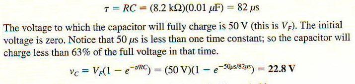
39
40 Determining the instantaneous voltage during capacitor discharge Determine the capacitor voltage 6 ms after the switch is closed The capacitor is charged
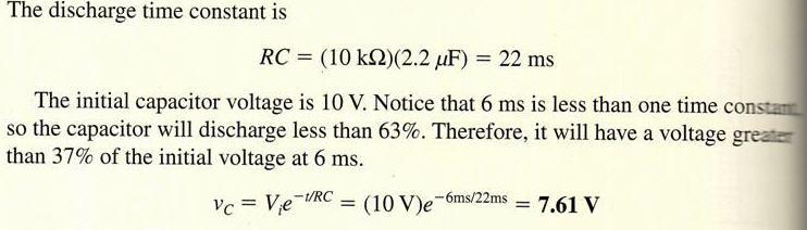
41
42 Capacitive Reactance, X C Capacitive reactance (X C ) is the opposition to sinusoidal current, expressed in ohms The rate of change of voltage is directly related to frequency As the frequency increases, the rate of change of voltage increases, and thus current ( i ) increases An increase in i means that there is less opposition to current (X C is less) X C is inversely proportional to i and to frequency
43 The current in a capacitive circuit varies directly with the frequency of the source voltage Because the voltage rate of change is higher at higher frequencies, the capacitive current increases proportionately with the frequency
44 For a fixed voltage and frequency, the current varies directly with the capacitance value Relationship of Capacitance and Current

45 Rate of change of a sine wave increases when frequency increases Formula for X C
46 Determine X C in the circuit below FIGURE 9-41 P khz
47 Ohm s Law for Capacitors V rms = I X C I rms = V rms /X c X c = V rms I

48 Determine the RMS Current in the circuit below Approx. Equivalent Circuit
49 Capacitors in ac Circuits When a sine wave signal is applied to a capacitor, the instantaneous capacitor current is equal to the capacitance times the instantaneous rate of change of the voltage across the capacitor This rate of change is a maximum positive when the rising sine wave crosses zero This rate of change is a maximum negative when the falling sine wave crosses zero The rate of change is zero at the maximum and minimum of the sine wave
50 The rates of change of a sine wave The higher the rate of voltage change, the higher the capacitor current
51 Analysis of Capacitive ac Circuit The current leads the voltage by 90 in a purely capacitive ac circuit (ICE) This is because: Current in a capacitor is dependent upon the rate of voltage change The highest rate of change in voltage is when it crosses zero volts. This is also when the capacitor is closer to being discharged and easily accepts higher current change. The least rate of change in voltage is near the peak voltage There is zero rate of change in voltage at peak. This is also when the capacitor is closest to being charged and doesn t easily accept much current change. Close to Discharged Close to Charged V C V S Close to Discharged Close to Charged
52 Current is always leading the capacitor voltage by 90 I C +90 o (Lead) V S, V C 0 o (Reference) Vector Diagram Close to Discharged Close to Charged Close to Discharged Close to Charged
53 Power in a Capacitor (Purely Capacitive Circuit) Energy is stored by the capacitor during a portion of the voltage cycle; then the stored energy is returned to the source during another portion of the cycle True power (P true ) is zero, since no energy is consumed by the capacitor. It just shifts back and forth between the cap and the source. Reactive Power (P r )The overall rate at which a capacitor stores and returns energy. Unit: (VAR) Instantaneous power (p) is the instantaneous product of v and i at any given time.
54 True Power (P true ) = 0 There is no energy dissipation, just energy transfer (Except for leakage current) The current just shifts back and forth between the cap and the source FIGURE 9-45 Power curve for a capacitor. (Reactive) Reactive Power Formulas Instantaneous Power: Instantaneous Values Power is 0 when either V or I are 0 Power is maximum when V or I are equal (positive or negative) Power Frequency is 2X the source frequency

55 Determine the true power and reactive power for the circuit below FIGURE 9-46 P true = 0
56 Capacitor Applications Since capacitors pass ac (Signals) and do not pass DC, they are used for DC blocking and ac signal coupling between circuit stages Capacitors are used for filtering in power supplies Capacitors are used to eliminate unwanted ac signals
57 An application of a capacitor used to block DC and couple ac in an amplifier Un-Biased Signal Biased Signal Capacitors Pass AC and Block DC (Pass Signals/Changing Current and Block DC)

58 FIGURE 9-55 Capacitively coupled amplifier.
59 Basic block diagram and operation of a dc power supply Capacitors can also be used to filter out unwanted signals or ripple
60 Half-wave and full-wave rectifier operation
61 Basic operation of a power supply filter capacitor The capacitance of the filter capacitor(s) is usually fairly large
62 Example of the operation of a bypass capacitor Input Output Unwanted Signal is Passed or Shunted to ground
63 More Capacitor Applications Capacitors are used in filters, to select one ac signal with a certain specified frequency from a wide range of signals with many different frequencies For example, the selection of one radio station and rejecting the others (High/Low/Bandpass Filters) Capacitors are used in timing circuits to generate time delays, based on the RC time constant Dynamic memories used in computers are simply very tiny capacitors used as a storage element
64 Checking a capacitor with an analog ohmmeter. This check shows a good capacitor.
65 A typical capacitance meter. (Courtesy of B+K Precision) Capacitance meters are also included in most modern multimeters too
Chapter 13. Capacitors
 Chapter 13 Capacitors Objectives Describe the basic structure and characteristics of a capacitor Discuss various types of capacitors Analyze series capacitors Analyze parallel capacitors Analyze capacitive
The Basic Capacitor. Dielectric. Conductors
 Chapter 9 The Basic Capacitor Capacitors are one of the fundamental passive components. In its most basic form, it is composed of two conductive plates separated by an insulating dielectric. The ability
CAPACITANCE. Capacitor. Because of the effect of capacitance, an electrical circuit can store energy, even after being de-energized.
 D ircuits APAITANE APAITANE Because of the effect of capacitance, an electrical circuit can store energy, even after being de-energized. EO 1.5 EO 1.6 EO 1.7 EO 1.8 EO 1.9 DESRIBE the construction of a
Electro - Principles I
 Electro - Principles I Capacitance The Capacitor What is it? Page 8-1 The capacitor is a device consisting essentially of two conducting surfaces separated by an insulating material. + Schematic Symbol
Trade of Electrician Standards Based Apprenticeship Capacitance Phase 2 Module No. 2.1 Unit No COURSE NOTES
 Trade of Electrician Standards Based Apprenticeship Capacitance Phase 2 Module No. 2.1 Unit No. 2.1.8 COURSE NOTES Certification & Standards Department Created by Gerry Ryan - Galway TC Revision 1 April
Capacitor Construction
 Capacitor Construction Topics covered in this presentation: Capacitor Construction 1 of 13 Introduction to Capacitors A capacitor is a device that is able to store charge and acts like a temporary, rechargeable
CIRCUIT ELEMENT: CAPACITOR
 CIRCUIT ELEMENT: CAPACITOR PROF. SIRIPONG POTISUK ELEC 308 Types of Circuit Elements Two broad types of circuit elements Ati Active elements -capable of generating electric energy from nonelectric energy
Capacitors are devices which can store electric charge. They have many applications in electronic circuits. They include:
 CAPACITORS Capacitors are devices which can store electric charge They have many applications in electronic circuits They include: forming timing elements, waveform shaping, limiting current in AC circuits
EDEXCEL NATIONAL CERTIFICATE. UNIT 38 ELECTRICAL and ELECTRONIC PRINCIPLES OUTCOME 2
 EDEXCEL NATIONAL CERTIFICATE UNIT 38 ELECTRICAL and ELECTRONIC PRINCIPLES OUTCOME 2 Electric fields and capacitors Electric fields: electrostatics, charge, electron movement in field, force on unit charge,
The Basic Capacitor. Water Tower / Capacitor Analogy. "Partnering With Our Clients for Combined Success"
 CAPACITOR BASICS I How s Work The Basic A capacitor is an electrical device which serves to store up electrical energy for release at a predetermined time. In its most basic form, it is comprised of three
Circuit Analysis-II. Circuit Analysis-II Lecture # 5 Monday 23 rd April, 18
 Circuit Analysis-II Capacitors in AC Circuits Introduction ü The instantaneous capacitor current is equal to the capacitance times the instantaneous rate of change of the voltage across the capacitor.
ENGR 2405 Chapter 6. Capacitors And Inductors
 ENGR 2405 Chapter 6 Capacitors And Inductors Overview This chapter will introduce two new linear circuit elements: The capacitor The inductor Unlike resistors, these elements do not dissipate energy They
Capacitors. Charging a Capacitor. Charge and Capacitance. L05: Capacitors and Inductors
 L05: Capacitors and Inductors 50 Capacitors 51 Outline of the lecture: Capacitors and capacitance. Energy storage. Capacitance formula. Types of capacitors. Inductors and inductance. Inductance formula.
The Farad is a very big unit so the following subdivisions are used in
 Passages in small print are for interest and need not be learnt for the R.A.E. Capacitance Consider two metal plates that are connected to a battery. The battery removes a few electrons from plate "A"
Properties of Capacitors and its DC Behavior
 LABORATORY Experiment 2 Properties of Capacitors and its DC Behavior 1. Objectives To investigate the /V characteristics of capacitor. To calculate the equivalent capacitance of capacitors connected in
Experiment FT1: Measurement of Dielectric Constant
 Experiment FT1: Measurement of Dielectric Constant Name: ID: 1. Objective: (i) To measure the dielectric constant of paper and plastic film. (ii) To examine the energy storage capacity of a practical capacitor.
RADIO AMATEUR EXAM GENERAL CLASS
 RAE-Lessons by 4S7VJ 1 CHAPTER- 2 RADIO AMATEUR EXAM GENERAL CLASS By 4S7VJ 2.1 Sine-wave If a magnet rotates near a coil, an alternating e.m.f. (a.c.) generates in the coil. This e.m.f. gradually increase
Lab 5 AC Concepts and Measurements II: Capacitors and RC Time-Constant
 EE110 Laboratory Introduction to Engineering & Laboratory Experience Lab 5 AC Concepts and Measurements II: Capacitors and RC Time-Constant Capacitors Capacitors are devices that can store electric charge
Electronics Capacitors
 Electronics Capacitors Wilfrid Laurier University October 9, 2015 Capacitor an electronic device which consists of two conductive plates separated by an insulator Capacitor an electronic device which consists
Chapter 10 EMT1150 Introduction to Circuit Analysis
 Chapter 10 EM1150 Introduction to Circuit Analysis Department of Computer Engineering echnology Fall 2018 Prof. Rumana Hassin Syed Chapter10 Capacitors Introduction to Capacitors he Electric Field Capacitance
 Capacitors and Inductors Resistor: a passive element which dissipates energy only Two important passive linear circuit elements: 1) Capacitor 2) Inductor Introduction Capacitor and inductor can store energy
E40M Capacitors. M. Horowitz, J. Plummer, R. Howe
 E40M Capacitors 1 Reading Reader: Chapter 6 Capacitance A & L: 9.1.1, 9.2.1 2 Why Are Capacitors Useful/Important? How do we design circuits that respond to certain frequencies? What determines how fast
Capacitors Diodes Transistors. PC200 Lectures. Terry Sturtevant. Wilfrid Laurier University. June 4, 2009
 Wilfrid Laurier University June 4, 2009 Capacitor an electronic device which consists of two conductive plates separated by an insulator Capacitor an electronic device which consists of two conductive
NABTEB Past Questions and Answers - Uploaded online
 MAY/JUNE 2008 Question & Model Answer IN BASIC ELECTRICITY 194 QUESTION 1 1(a) Explain the following terms in relation to atomic structure (i) Proton Neutron (iii) Electron (b) Three cells of emf 1.5 volts
Besides resistors, capacitors are one of the most common electronic components that you will encounter. Sometimes capacitors are components that one
 1 Besides resistors, capacitors are one of the most common electronic components that you will encounter. Sometimes capacitors are components that one would deliberately add to a circuit. Other times,
Capacitors. David Frazier and John Ingram
 Capacitors David Frazier and John Ingram Introduction Used in most electronic devices Comes in a variety of sizes Basic Function The basic function of a capacitor is to store energy. Common usage include
DEPARTMENT OF ELECTRONIC ENGINEERING ELECTRONIC WORKSHOP # 04. Capacitors
 MEHRAN UNIVERSITY OF ENGINEERING AND TECHNOLOGY, JAMSHORO DEPARTMENT OF ELECTRONIC ENGINEERING ELECTRONIC WORKSHOP # 04 Capacitors Roll. No: Checked by: Date: Grade: Object: To become familiar with Capacitors,
A capacitor is a device that stores electric charge (memory devices). A capacitor is a device that stores energy E = Q2 2C = CV 2
. A capacitor is a device that stores energy E = Q2 2C = CV 2") Capacitance: Lecture 2: Resistors and Capacitors Capacitance (C) is defined as the ratio of charge (Q) to voltage (V) on an object: C = Q/V = Coulombs/Volt = Farad Capacitance of an object depends on geometry
Capacitance: Lecture 2: Resistors and Capacitors Capacitance (C) is defined as the ratio of charge (Q) to voltage (V) on an object: C = Q/V = Coulombs/Volt = Farad Capacitance of an object depends on geometry
Some Important Electrical Units
 Some Important Electrical Units Quantity Unit Symbol Current Charge Voltage Resistance Power Ampere Coulomb Volt Ohm Watt A C V W W These derived units are based on fundamental units from the meterkilogram-second
CAPACITANCE. Figure 1(a). Figure 1(b).
. Figure 1(b).") Reading 11 Ron Bertrand VK2DQ http://www.radioelectronicschool.com CAPACITANCE In this reading we are going to talk about capacitance. I have to make a distinction here between capacitor and capacitance.
Reading 11 Ron Bertrand VK2DQ http://www.radioelectronicschool.com CAPACITANCE In this reading we are going to talk about capacitance. I have to make a distinction here between capacitor and capacitance.
ECE2262 Electric Circuits. Chapter 6: Capacitance and Inductance
 ECE2262 Electric Circuits Chapter 6: Capacitance and Inductance Capacitors Inductors Capacitor and Inductor Combinations Op-Amp Integrator and Op-Amp Differentiator 1 CAPACITANCE AND INDUCTANCE Introduces
Introduction to AC Circuits (Capacitors and Inductors)
") Introduction to AC Circuits (Capacitors and Inductors) Amin Electronics and Electrical Communications Engineering Department (EECE) Cairo University elc.n102.eng@gmail.com http://scholar.cu.edu.eg/refky/
Introduction to AC Circuits (Capacitors and Inductors) Amin Electronics and Electrical Communications Engineering Department (EECE) Cairo University elc.n102.eng@gmail.com http://scholar.cu.edu.eg/refky/
Figure 1: Capacitor circuit
 Capacitors INTRODUCTION The basic function of a capacitor 1 is to store charge and thereby electrical energy. This energy can be retrieved at a later time for a variety of uses. Often, multiple capacitors
Lecture 20. March 22/24 th, Capacitance (Part I) Chapter , Pages
 Chapter , Pages") Lecture 0 March /4 th, 005 Capacitance (Part I) Reading: Boylestad s Circuit Analysis, 3 rd Canadian Edition Chapter 10.1-6, Pages 8-94 Assignment: Assignment #10 Due: March 31 st, 005 Preamble: Capacitance
Lecture 0 March /4 th, 005 Capacitance (Part I) Reading: Boylestad s Circuit Analysis, 3 rd Canadian Edition Chapter 10.1-6, Pages 8-94 Assignment: Assignment #10 Due: March 31 st, 005 Preamble: Capacitance
Coulomb s constant k = 9x10 9 N m 2 /C 2
 1 Part 2: Electric Potential 2.1: Potential (Voltage) & Potential Energy q 2 Potential Energy of Point Charges Symbol U mks units [Joules = J] q 1 r Two point charges share an electric potential energy
In addition to resistors that we have considered to date, there are two other basic electronic components that can be found everywhere: the capacitor
 In addition to resistors that we have considered to date, there are two other basic electronic components that can be found everywhere: the capacitor and the inductor. We will consider these two types
EDEXCEL NATIONALS UNIT 5 - ELECTRICAL AND ELECTRONIC PRINCIPLES. ASSIGNMENT No.2 - CAPACITOR NETWORK
 EDEXCEL NATIONALS UNIT 5 - ELECTRICAL AND ELECTRONIC PRINCIPLES ASSIGNMENT No.2 - CAPACITOR NETWORK NAME: I agree to the assessment as contained in this assignment. I confirm that the work submitted is
REVISED HIGHER PHYSICS REVISION BOOKLET ELECTRONS AND ENERGY
 REVSED HGHER PHYSCS REVSON BOOKLET ELECTRONS AND ENERGY Kinross High School Monitoring and measuring a.c. Alternating current: Mains supply a.c.; batteries/cells supply d.c. Electrons moving back and forth,
Compiled and rearranged by Sajit Chandra Shakya
 1 (a) Define capacitance. [May/June 2005] 1...[1] (b) (i) One use of a capacitor is for the storage of electrical energy. Briefly explain how a capacitor stores energy......[2] (ii) Calculate the change
Chapter 2: Capacitor And Dielectrics
 hapter 2: apacitor And Dielectrics In this chapter, we are going to discuss the different ways that a capacitor could be arranged in a circuit and how its capacitance could be increased. Overview apacitor
RC, RL, and LCR Circuits
 RC, RL, and LCR Circuits EK307 Lab Note: This is a two week lab. Most students complete part A in week one and part B in week two. Introduction: Inductors and capacitors are energy storage devices. They
Unit-2.0 Circuit Element Theory
 Unit2.0 Circuit Element Theory Dr. Anurag Srivastava Associate Professor ABVIIITM, Gwalior Circuit Theory Overview Of Circuit Theory; Lumped Circuit Elements; Topology Of Circuits; Resistors; KCL and KVL;
Parallel Plate Capacitor, cont. Parallel Plate Capacitor, final. Capacitance Isolated Sphere. Capacitance Parallel Plates, cont.
 Chapter 6 Capacitance and Dielectrics Capacitors! Capacitors are devices that store electric charge! Examples of where capacitors are used include:! radio receivers (tune frequency)! filters in power supplies!
CAPACITORS / CAPACITANCE ECET11
 APAITORS / APAITANE - apacitance - apacitor types - apacitors in series & parallel - R ircuit harging phase - R ircuit Discharging phase - R ircuit Steady State model - Source onversions - Superposition
Introduction to Capacitor Technologies. What is a Capacitor?
 Introduction to Capacitor Technologies What is a Capacitor? 2013 Table of Contents Introduction... 3 Capacitor Construction, Parameters and Properties... 3 Capacitor Construction... 3 Capacitor Parameters...
Chapter 24. Capacitance and Dielectrics Lecture 1. Dr. Armen Kocharian
 Chapter 24 Capacitance and Dielectrics Lecture 1 Dr. Armen Kocharian Capacitors Capacitors are devices that store electric charge Examples of where capacitors are used include: radio receivers filters
7/06 Electric Fields and Energy
 Part ASome standard electric field and potential configurations About this lab: Electric fields are created by electric charges and exert force on charges. Electric potential gives an alternative description.
Definition of Capacitance
 Definition of Capacitance The capacitance, C, of a capacitor is defined as the ratio of the magnitude of the charge on either conductor to the potential difference between the conductors Q C = ΔV The SI
SECTION #1 - The experimental setup
 Lemon Battery Connected in Series Charging a 2.2 Farad Capacitor SECTION #1 - The experimental setup 1. The goal of this experiment is to see if I can connect 2, 3 or 4 lemons together in a series configuration
[1] (b) Fig. 1.1 shows a circuit consisting of a resistor and a capacitor of capacitance 4.5 μf. Fig. 1.1
![[1] (b) Fig. 1.1 shows a circuit consisting of a resistor and a capacitor of capacitance 4.5 μf. Fig. 1.1](/thumbs/81/83276652.jpg "[1] (b) Fig. 1.1 shows a circuit consisting of a resistor and a capacitor of capacitance 4.5 μf. Fig. 1.1") 1 (a) Define capacitance..... [1] (b) Fig. 1.1 shows a circuit consisting of a resistor and a capacitor of capacitance 4.5 μf. S 1 S 2 6.3 V 4.5 μf Fig. 1.1 Switch S 1 is closed and switch S 2 is left
1 (a) Define capacitance..... [1] (b) Fig. 1.1 shows a circuit consisting of a resistor and a capacitor of capacitance 4.5 μf. S 1 S 2 6.3 V 4.5 μf Fig. 1.1 Switch S 1 is closed and switch S 2 is left
Capacitance. A capacitor consists of two conductors that are close but not touching. A capacitor has the ability to store electric charge.
 Capacitance A capacitor consists of two conductors that are close but not touching. A capacitor has the ability to store electric charge. a) Parallel-plate capacitor connected to battery. (b) is a circuit
Name Date Time to Complete
 Name Date Time to Complete h m Partner Course/ Section / Grade Capacitance Equipment Doing some simple experiments, including making and measuring the capacitance of your own capacitor, will help you better
Outline. ECE 477 Digital Systems Senior Design Project. Module 7 Capacitor Selection Guidelines. Film Ceramic Electrolytic Miscellaneous
 Module 7: Capacitor Selection Guidelines Lecture Workbook - Page 7-1 2004 by D. G. Meyer ECE 477 Digital Systems Senior Design Project Module 7 Capacitor Selection Guidelines Outline Film Ceramic Electrolytic
shown in Fig. 4, is initially uncharged. How much energy is stored in the two capacitors after the switch S is closed for long time?
 Chapter 25 Term 083 Q13. Each of the two 25-µF capacitors, as shown in Fig. 3, is initially uncharged. How many Coulombs of charge pass through ammeter A after the switch S is closed for long time? A)
EXPERIMENT 07 TO STUDY DC RC CIRCUIT AND TRANSIENT PHENOMENA
 EXPERIMENT 07 TO STUDY DC RC CIRCUIT AND TRANSIENT PHENOMENA DISCUSSION The capacitor is a element which stores electric energy by charging the charge on it. Bear in mind that the charge on a capacitor
FEATURES AND APPLICATIONS OF POLYMER THIN FILM MULTI-LAYER CAPACITOR PML CAP
 FEATURES AND APPLICATIONS OF POLYMER THIN FILM MULTI-LAYER CAPACITOR PML CAP PML CAP Polymer Multi-Layer Capacitor (PML CAP) is a surface mounting capacitor with multiple metal-deposited polymer layers
Introduction to Basic Electronics Lecture -2
 Introduction to Basic Electronics Lecture -2 Basic Electronics What is electricity? Voltage, Current, Resistance DC/AC Ohm s Law Capacitors & Inductors Conductor & Insulator What is Electricity? Everything
ELECTROMAGNETIC OSCILLATIONS AND ALTERNATING CURRENT
 Chapter 31: ELECTROMAGNETIC OSCILLATIONS AND ALTERNATING CURRENT 1 A charged capacitor and an inductor are connected in series At time t = 0 the current is zero, but the capacitor is charged If T is the
Direct Current (DC) Circuits
 Circuits") Direct Current (DC) Circuits NOTE: There are short answer analysis questions in the Participation section the informal lab report. emember to include these answers in your lab notebook as they will be
Direct Current (DC) Circuits NOTE: There are short answer analysis questions in the Participation section the informal lab report. emember to include these answers in your lab notebook as they will be
Chapter 26. Capacitance and Dielectrics
 Chapter 26 Capacitance and Dielectrics Capacitors Capacitors are devices that store electric charge Examples of where capacitors are used include: radio receivers filters in power supplies energy-storing
ECE2262 Electric Circuits. Chapter 6: Capacitance and Inductance
 ECE2262 Electric Circuits Chapter 6: Capacitance and Inductance Capacitors Inductors Capacitor and Inductor Combinations 1 CAPACITANCE AND INDUCTANCE Introduces two passive, energy storing devices: Capacitors
SECTION 3 BASIC AUTOMATIC CONTROLS UNIT 12 BASIC ELECTRICITY AND MAGNETISM
 SECTION 3 BASIC AUTOMATIC CONTROLS UNIT 12 BASIC ELECTRICITY AND MAGNETISM Unit Objectives Describe the structure of an atom. Identify atoms with a positive charge and atoms with a negative charge. Explain
farads or 10 µf. The letter indicates the part tolerance (how close should the actual value be to the marking).
.") p1 EE1050/60 Capacitors Lab University of Utah Electrical Engineering Department EE1050/1060 Capacitors A. Stolp, 10/4/99 rev 3/17/01 Objectives 1.) Observe charging and discharging of a capacitor. 2.)
p1 EE1050/60 Capacitors Lab University of Utah Electrical Engineering Department EE1050/1060 Capacitors A. Stolp, 10/4/99 rev 3/17/01 Objectives 1.) Observe charging and discharging of a capacitor. 2.)
EXPERIMENT 5A RC Circuits
 EXPERIMENT 5A Circuits Objectives 1) Observe and qualitatively describe the charging and discharging (decay) of the voltage on a capacitor. 2) Graphically determine the time constant for the decay, τ =.
Lab #4 Capacitors and Inductors. Capacitor Transient and Steady State Response
 Capacitor Transient and Steady State Response Like resistors, capacitors are also basic circuit elements. Capacitors come in a seemingly endless variety of shapes and sizes, and they can all be represented
Exercise 1: Capacitors
 Capacitance AC 1 Fundamentals Exercise 1: Capacitors EXERCISE OBJECTIVE When you have completed this exercise, you will be able to describe the effect a capacitor has on dc and ac circuits by using measured
Electrical Engineering Fundamentals for Non-Electrical Engineers
 Electrical Engineering Fundamentals for Non-Electrical Engineers by Brad Meyer, PE Contents Introduction... 3 Definitions... 3 Power Sources... 4 Series vs. Parallel... 9 Current Behavior at a Node...
Pretest ELEA1831 Module 11 Units 1& 2 Inductance & Capacitance
 Pretest ELEA1831 Module 11 Units 1& 2 Inductance & Capacitance 1. What is Faraday s Law? Magnitude of voltage induced in a turn of wire is proportional to the rate of change of flux passing through that
Name: Lab Partner: Section:
 Chapter 6 Capacitors and RC Circuits Name: Lab Partner: Section: 6.1 Purpose The purpose of this experiment is to investigate the physics of capacitors in circuits. The charging and discharging of a capacitor
Elizabethtown College Department of Physics and Engineering PHY104
 Elizabethtown College Department of Physics and Engineering PHY104 Lab #7- Capacitors 1. Introduction The capacitor is one of the essential elements of analog circuitry. It is highly useful for its energy
DEPARTMENT OF COMPUTER ENGINEERING UNIVERSITY OF LAHORE
 DEPARTMENT OF COMPUTER ENGINEERING UNIVERSITY OF LAHORE NAME. Section 1 2 3 UNIVERSITY OF LAHORE Department of Computer engineering Linear Circuit Analysis Laboratory Manual 2 Compiled by Engr. Ahmad Bilal
Capacitor investigations
 Sensors: Loggers: Voltage Any EASYSENSE Capacitor investigations Logging time: EasyLog (20 s) Teacher s notes 01 Time constant for a capacitor - resistor circuit Theory The charging and discharging of
Prof. Anyes Taffard. Physics 120/220. Voltage Divider Capacitor RC circuits
 Prof. Anyes Taffard Physics 120/220 Voltage Divider Capacitor RC circuits Voltage Divider The figure is called a voltage divider. It s one of the most useful and important circuit elements we will encounter.
Learnabout Electronics - AC Theory
 Learnabout Electronics - AC Theory Facts & Formulae for AC Theory www.learnabout-electronics.org Contents AC Wave Values... 2 Capacitance... 2 Charge on a Capacitor... 2 Total Capacitance... 2 Inductance...
Summary Notes ALTERNATING CURRENT AND VOLTAGE
 HIGHER CIRCUIT THEORY Wheatstone Bridge Circuit Any method of measuring resistance using an ammeter or voltmeter necessarily involves some error unless the resistances of the meters themselves are taken
(d) describe the action of a 555 monostable timer and then use the equation T = 1.1 RC, where T is the pulse duration
 describe the action of a 555 monostable timer and then use the equation T = 1.1 RC, where T is the pulse duration") Chapter 1 - Timing Circuits GCSE Electronics Component 2: Application of Electronics Timing Circuits Learners should be able to: (a) describe how a RC network can produce a time delay (b) describe how
Chapter 1 - Timing Circuits GCSE Electronics Component 2: Application of Electronics Timing Circuits Learners should be able to: (a) describe how a RC network can produce a time delay (b) describe how
Charging and discharging of a capacitor
 5. Charging and discharging of a capacitor 5.1 Capacitors Figure 5.1: A system of charges, physically separated, has potential energy. The simplest example is that of two metal plates of large area carrying
BASIC ELECTRONICS PROF. T.S. NATARAJAN DEPT OF PHYSICS IIT MADRAS LECTURE-3 ELECTRONIC DEVICES -II RESISTOR SERIES & PARALLEL
 BASIC ELECTRONICS PROF. T.S. NATARAJAN DEPT OF PHYSICS IIT MADRAS LECTURE-3 ELECTRONIC DEVICES -II RESISTOR SERIES & PARALLEL Hello everybody we are doing a course on basic electronics by the method of
ALUMINUM ELECTROLYTIC CAPACITORS Capacitor Life
 1 of 8 5/12/2008 10:23 PM Home About Us Products Contact Us Info Other Links Aluminum Part # Search ALUMINUM ELECTROLYTIC CAPACITORS Capacitor Life Table of Contents Capacitor Life The life of aluminum
Episode 125: Introducing capacitors
 Episode 125: Introducing capacitors It is helpful to start this topic by discussing capacitors, rather than the more abstract notion of capacitance. Summary Demonstration: A super-capacitor. (10 minutes)
6. Introduction and Chapter Objectives
 Real Analog - Circuits Chapter 6: Energy Storage Elements 6. Introduction and Chapter Objectives So far, we have considered circuits that have been governed by algebraic relations. These circuits have,
Experiment 4. RC Circuits. Observe and qualitatively describe the charging and discharging (decay) of the voltage on a capacitor.
 of the voltage on a capacitor.") Experiment 4 RC Circuits 4.1 Objectives Observe and qualitatively describe the charging and discharging (decay) of the voltage on a capacitor. Graphically determine the time constant τ for the decay. 4.2
Experiment 4 RC Circuits 4.1 Objectives Observe and qualitatively describe the charging and discharging (decay) of the voltage on a capacitor. Graphically determine the time constant τ for the decay. 4.2
Sinusoidal Response of RLC Circuits
 Sinusoidal Response of RLC Circuits Series RL circuit Series RC circuit Series RLC circuit Parallel RL circuit Parallel RC circuit R-L Series Circuit R-L Series Circuit R-L Series Circuit Instantaneous
Lab 08 Capacitors 2. Figure 2 Series RC circuit with SPDT switch to charge and discharge capacitor.
 Lab 08: Capacitors Last edited March 5, 2018 Learning Objectives: 1. Understand the short-term and long-term behavior of circuits containing capacitors. 2. Understand the mathematical relationship between
University of TN Chattanooga Physics 1040L 8/18/2012 PHYSICS 1040L LAB LAB 4: R.C. TIME CONSTANT LAB
 PHYSICS 1040L LAB LAB 4: R.C. TIME CONSTANT LAB OBJECT: To study the discharging of a capacitor and determine the time constant for a simple circuit. APPARATUS: Capacitor (about 24 μf), two resistors (about
PHY222 - Lab 7 RC Circuits: Charge Changing in Time Observing the way capacitors in RC circuits charge and discharge.
 PHY222 Lab 7 RC Circuits: Charge Changing in Time Observing the way capacitors in RC circuits charge and discharge. Print Your Name Print Your Partners' Names You will return this handout to the instructor
Electromagnetic Oscillations and Alternating Current. 1. Electromagnetic oscillations and LC circuit 2. Alternating Current 3.
 Electromagnetic Oscillations and Alternating Current 1. Electromagnetic oscillations and LC circuit 2. Alternating Current 3. RLC circuit in AC 1 RL and RC circuits RL RC Charging Discharging I = emf R
Electric Currents and Circuits
 Nicholas J. Giordano www.cengage.com/physics/giordano Chapter 19 Electric Currents and Circuits Marilyn Akins, PhD Broome Community College Electric Circuits The motion of charges leads to the idea of
Chapter 2: Capacitors And Dielectrics
 hapter 2: apacitors And Dielectrics 2.1 apacitance and capacitors in series and parallel L.O 2.1.1 Define capacitance and use capacitance apacitor is a device that is capable of storing electric charges
Practical 1 RC Circuits
 Objectives Practical 1 Circuits 1) Observe and qualitatively describe the charging and discharging (decay) of the voltage on a capacitor. 2) Graphically determine the time constant for the decay, τ =.
Measuring the time constant for an RC-Circuit
 Physics 8.02T 1 Fall 2001 Measuring the time constant for an RC-Circuit Introduction: Capacitors Capacitors are circuit elements that store electric charge Q according to Q = CV where V is the voltage
MAY/JUNE 2006 Question & Model Answer IN BASIC ELECTRICITY 194
 MAY/JUNE 2006 Question & Model Answer IN BASIC ELECTRICITY 194 Question 1 (a) List three sources of heat in soldering (b) state the functions of flux in soldering (c) briefly describe with aid of diagram
PHYSICS 171 UNIVERSITY PHYSICS LAB II. Experiment 6. Transient Response of An RC Circuit
 PHYSICS 171 UNIVERSITY PHYSICS LAB II Experiment 6 Transient Response of An RC Circuit Equipment: Supplies: Function Generator, Dual Trace Oscilloscope.002 Microfarad, 0.1 Microfarad capacitors; 1 Kilohm,
ENERGY AND TIME CONSTANTS IN RC CIRCUITS By: Iwana Loveu Student No Lab Section: 0003 Date: February 8, 2004
 ENERGY AND TIME CONSTANTS IN RC CIRCUITS By: Iwana Loveu Student No. 416 614 5543 Lab Section: 0003 Date: February 8, 2004 Abstract: Two charged conductors consisting of equal and opposite charges forms
Capacitors. The charge Q on a capacitor s plate is proportional to the potential difference V across the Q = C V (1)
") apacitors THEORY The charge Q on a capacitor s plate is proportional to the potential difference V across the capacitor. We express this with Q = V (1) where is a proportionality constant known as the
apacitors THEORY The charge Q on a capacitor s plate is proportional to the potential difference V across the capacitor. We express this with Q = V (1) where is a proportionality constant known as the
Capacitance and capacitors. Dr. Loai Afana
 apacitance and capacitors apacitors apacitors are devices that store energy in an electric field. apacitors are used in many every-day applications Heart defibrillators amera flash units apacitors are
Understanding EEStor Parameters
 Understanding EEStor Parameters This primer is intended to help readers understand the technical data published by EEStor. There are three key parameters and two formulas that are important to the understanding
Type FCA Acrylic Surface Mount Film Capacitors
 Type Acrylic Surface Mount Film Capacitors Acrylic Stacked Metallized Film Capacitors for Filtering and Noise Attenuation Type acrylic film chips are non-inductive stacked metallized film capacitors which
Lab #6 Ohm s Law. Please type your lab report for Lab #6 and subsequent labs.
 Dr. Day, Fall 2004, Rev. 06/22/10 HEFW PH 262 Page 1 of 4 Lab #6 Ohm s Law Please type your lab report for Lab #6 and subsequent labs. Objectives: When you have completed this lab exercise you should be
Chapter 26. Capacitance and Dielectrics
 Chapter 26 Capacitance and Dielectrics Capacitors Capacitors are devices that store electric charge Examples of where capacitors are used include: radio receivers filters in power supplies to eliminate