Understanding the dynamics and energetics of magnetic reconnection in a laboratory plasma: Review of recent progress on selected fronts
|
|
|
- Lorraine Gray
- 5 years ago
- Views:
Transcription
1 Understanding the dynamics and energetics of magnetic reconnection in a laboratory plasma: Review of recent progress on selected fronts Masaaki Yamada, Jongsoo Yoo, and Clayton E. Myers Princeton Plasma Physics Laboratory, Princeton, New Jersey, USA 8543 Magnetic reconnection is a fundamental process at work in laboratory, space and astrophysical plasmas, in which magnetic field lines change their topology and convert magnetic energy to plasma particles by acceleration and heating. One of the most important problems in reconnection research has been to understand why reconnection occurs so much faster than predicted by MHD theory. Following the recent pedagogical review of this subject [M. Yamada, R. Kulsrud, and H. Ji, Rev. Mod. Phys. 82, 63 (21)], this paper presents a review of more recent discoveries and findings in the research of fast magnetic reconnection in laboratory, space, and astrophysical plasmas. In spite of the huge difference in physical scales, we find remarkable commonality between the characteristics of the magnetic reconnection in laboratory and space plasmas. In this paper, we will focus especially on the energy flow, a key feature of the reconnection process. In particular the experimental results on the energy conversion and partitioning in a laboratory reconnection layer [M. Yamada et al., Nat. Commu. 5, 4474 (214)] are discussed and compared with quantitative estimates based on two-fluid analysis. In the Magnetic Reconnection Experiment (MRX), we find that energy deposition to electrons is localized near the X-point and is mostly from the electric field component perpendicular to the magnetic field. The mechanisms of ion acceleration and heating are also identified and a systematic and quantitative study on the inventory of converted energy within a reconnection layer with a well-defined but variable boundary. The measured energy partition in a reconnection region of similar effective size (L 3 ion skin depths) of the Earth s magneto-tail [J. Eastwood et al., Phys. Rev. Lett. 11, 2251 (213)] is notably consistent with our laboratory results. Finally, to study the global aspects of magnetic reconnection, we have carried out a laboratory experiment on the sta-
2 2 bility criteria for solar flare eruptions, including storage and release mechanisms of magnetic energy. We show that toroidal magnetic flux generated by magnetic relaxation (reconnection) processes generates a new stabilizing force which prevents plasma eruption. This result has lead us to discovery of a new stabilizing force for solar flares [C. E. Myers et al., Nature 528, 526 (215)]. PACS numbers: Vd, q I. INTRODUCTION In this paper, recent progress in several selected subtopics of magnetic reconnection research is discussed. In particular, the dynamics of ions and electrons in a prototypical reconnection layer is discussed in the context of two-fluid physics. The study of the mechanisms of energy conversion and energy partitioning in a collision-free reconnection layer (current sheet) in a laboratory plasma has made great progress and the results are compared with numerical analysis as well as with satellite measurements in the magnetotail. In addition, the impulsive nature of the global aspect of magnetic reconnection has been investigated through the evolution of flux ropes generated in a laboratory between the two line-tied boundaries. Our major results are presented along with a discussion on their relevance to the dynamics of solar flare and coronal mass ejection (CME) phenomena. Fast reconnection of magnetic field lines occurs where two regions of magnetized plasma meet and where the magnetic field shear increases. The movement of magnetic field lines caused by external forcing or by change of the global boundary conditions leads to formation of a current layer and magnetic reconnection is driven. In the local reconnection layer, the reconnection rate is determined by the physical mechanisms of the current layer. The local reconnection in turn influences the global configuration by determining the amount of magnetic flux transfer through the current layer. The reconnection speed is characterized by the amount of field lines moving from one section to another that is topologically separated. Historically, one of the most important questions on magnetic reconnection has been why reconnection occurs so fast in comparison with the rate predicted by classical MHD theory [1, 2]. During the past two decades, important progress in understanding the physics of fast collisionless reconnection has been made through numerical simulations, observations from
3 3 satellites, and dedicated laboratory plasma experiments [3, 4]. It is now established that two-fluid effects [3 6], which are derived from the fundamentally different behavior of ions and electrons, are important within the critical reconnection layer where reconnection takes place. In previous studies of the physics of the reconnection layer, important progress has been made in understanding fast collisionless reconnection. Hall effects are now considered to be responsible for the fast reconnection observed in the collisionless neutral sheets generated in the reconnection layer of the magnetosphere and laboratory plasmas. In one-fluid MHD formulation, the difference between the fluid velocity of electrons and ions is supposed to be much smaller than the Alfén velocity or the ion velocity. This one-fluid approximation criterion, however, does not often hold in the reconnection layer because of a sizable amount of neutral sheet current flows there; namely, electrons and ions move quite differently and the two-fluid formulation becomes more appropriate. Generally, the twofluid formulation implies that the electron and ion distribution functions are close to shifted Maxwellians, and this imposes constrains on the level of collisionality required for such description [7, 8]. Here, by two-fluid reconnection, we mean that the reconnection dynamics can be described by the generalized Ohm s law, which is valid for arbitrary distribution functions. Major findings in the past decade regarding two-fluid effects are as follows: - Hall effects have been verified by observations of an out-of-reconnection-plane quadrupolar magnetic field structure in the prototypical reconnection layer, in numerical simulations, dedicated laboratory experiments and space satellite data. - In the laboratory experiment, the reconnection rate is found to increase rapidly as the ratio of the electron mean free path to the scale length increases [9]. This finding provides evidence for two-fluid effects being responsible for the observed fast reconnection rate in collision-free plasmas. - Electrostatic and electromagnetic fluctuations are observed in the reconnection layer of laboratory and space plasmas with notable similarities in their characteristics. Although some correlation was seen between the reconnection rate and the amplitude of electromagnetic waves in laboratory experiments, a causal relationship is yet to be found. Recently, the major focus of laboratory reconnection research has shifted to investigation of the key mechanisms of energy conversion from the magnetic field to particle kinetic energy across reconnection regions of various scale sizes. This is perhaps the most important
4 4 problem in magnetic reconnection research, since it is the energy conversion mechanisms that are often of primary interest. This is especially important in heliospheric and astrophysical applications where reconnection is widely invoked as a mechanism underlying explosive and violent energy release, often powering spectacular high-energy emissions such as solar or stellar flares. An important aspect of plasma energization during reconnection is the acceleration of a large number of nonthermal particles to very high, sometimes relativistic, energies and their observable radiative signatures. Recent major findings and discoveries on the energetic of magnetic reconnection are: - An experimental study of the reconnection layer has been carried out in a laboratory plasma in the two-fluid physics regime. It was observed that the conversion of magnetic energy occurs across a region significantly larger than the narrow electron diffusion region previously considered. A saddle shaped electrostatic potential profile appears in the reconnection plane with a few ion skin-depth scale, and ions are accelerated by the resulting electric field at the separatrices. The accelerated ions are then thermalized by re-magnetization in the downstream region. - A quantitative inventory of the converted energy was documented in a reconnection layer of a laboratory plasma with a well-defined, variable boundary, and compared with a similar analysis of numerical simulations. This study concludes that about 5% of the inflowing magnetic energy is converted to particle energy, roughly 2/3 of which is ultimately transferred to ions and 1/3 to electrons. The results are consistent with recent space observations. These features of energy conversion and partitioning do not strongly depend on the size of the analysis region over the tested range of scales, approximately 2 to 4 ion skin depths. It is generally believed that if the magnetic energy of a low beta global MHD equilibrium state is lowered by a reorganization of plasma topology, reconnection must take place. Reconnection will stop if it no longer lowers the total magnetic energy. It is recognized that global reconnection (magnetic self-organization) phenomena almost always occur unsteadily or impulsively. Fast reconnection generally leads to an impulsive global topology change or global magnetic self-organization phenomena. Impulsive reconnection typically occurs after the gradual evolution of the global equilibrium builds up sufficient free energy in order to induce the motion of plasma or a topological change. In this paper, we investigate mechanisms that cause impulsive global reconnection phenomena through a study of toroidally shaped magnetic flux ropes generated by the plasma discharges between two electrodes.
5 5 Solar eruptions are driven by the sudden release of magnetic energy stored in the solar corona. In many cases, it is believed that the magnetic energy that drives the CME is stored in arched structures called line-tied magnetic flux ropes. We analyze our data based on the storage-and-release model for solar eruptions. In this model, eruptions are triggered by a global MHD instability in the corona rather than by dynamic fast flux injection at the solar surface. For an arched flux rope, the relative invariance of the solar surface translates to a slow driving mechanism at the two line-tied foot points. Previous laboratory arched flux rope experiments do not satisfy this storage-and-release condition by relying on the dynamic injection of either plasma or magnetic flux at the foot points to produce an eruption [1 12]. In contrast, the present MRX experiments enforce a clear separation of timescales between the foot-point driving time, and the dynamic Alfvén time, such that the observed eruptions are driven by storage-and-release mechanisms. The observed eruption of the flux rope shows a clear evidence for plasma motion caused by an ideal MHD instability, which generates currents sheets in and around the flux rope. The features of these current sheets and a new mechanism of self-organization of a flux rope are presented in this paper. In section II, we present how a current sheet is formed and discuss our recent findings on the dynamics of local magnetic reconnection layer. In section III, we present our theoretical consideration of the characteristics of energy flow in a prototypical reconnection layer, in section IV, a summary of the recent experimental results of the energy conversion and partitioning, and finally in section V, global magnetic reconnection phenomena of flux ropes generated in a laboratory in relationship to solar coronal mass ejection (CME), followed by a summary. II. DYNAMICS OF A CURRENT SHEET IN THE RECONNECTION LAYER Ideal magnetohydrodynamics (MHD), developed in the early 195s, describes the dynamics of highly conductive plasmas, wherein the electric field parallel to the magnetic field line (E ) vanishes [1, 2, 13]. In this model, magnetic field lines always move with the plasma. Any plasma on a given line stays on that line as it moves and cannot move to another line. This is basically the flux freezing process associated with ideal MHD. When two field lines approach very close to each other in a narrow region (Fig.1) and the magnetic field gradient becomes large, a current sheet is formed. The interaction of field lines in this sheet makes
6 6 FIG. 1: Magnetic energy is converted to plasma in magnetic reconnection. After reconnection occurs, the two newly connected field lines accelerate the plasma fluid due to a tension force generated by reconnection. When field lines are reconnected, the topology of magnetic configurations changes and the conversion of magnetic energy to kinetic energy occurs as the plasma gains energy. FIG. 2: Formation of current sheet by externally driven flow. Figure from Forbes [14]. E sufficiently large to induce non-ideal-mhd plasma behavior and to cause the magnetic field lines to lose their identity, break and reconnect. We called this a diffusion region. After reconnection takes place, the two newly connected field lines accelerate the plasma fluid due to a tension force generated by reconnection. Thus, there are two important aspects for magnetic reconnection; 1) the magnetic topology changes and 2) magnetic energy is converted to plasma kinetic energy. A. Analysis of magnetic reconnection layer in MHD About 6 years ago, plasma physicists considered, based solely on the MHD model, that when plasmas flow towards an X-point as shown in Fig. 2a, a current sheet should be formed in the plasma by the collapse of the X-point type neutral point and current is induced in this diffusion region as shown in Fig. 2(b) [14]. In vacuum this would not happen because B = µ J = everywhere. We can define this diffusion region in the MHD formulation as the region where E + V B = ηj with V defined as the plasma bulk flow velocity and η as the plasma resistivity. Outside of this region, the rest of the plasma satisfies E + V B =, the ideal MHD condition. It should be noted here that the definition of the diffusion layer would change drastically within the kinetic or two-fluid framework. Magnetic reconnection occurs throughout solar flares. When as sun spot shows up on the sun s surface, a helmet shape hot plasma region is often recognized nearby with a strong emission of X-ray: Fig. 3. This region generally has an arcade structure and magnetic
7 7 FIG. 3: Magnetic reconnection in solar flares. A current layer appears at the top of the arcade. Figure from Shibata et al. [15]. FIG. 4: Current sheets formed in the earth s magnetosphere for magnetic reconnection: red color regions. From reconnection takes place in the current layer on the top of this arcade. Plasma is accelerated in the reconnection layer at the top of arcade and impacts the loop top where we can see a lot of X-ray emission. This type of reconnection also generates phenomena called coronal mass ejection (CME). The CME events eject a large amount of plasma outward from the sun, generating solar winds. The solar winds carry magnetic field with them. When they arrive near the earth, they induce magnetic reconnection at first on the day-side front of magnetosphere: Fig. 4. The reconnected field lines are blown away with high (solar wind) speed and reach behind the earth, thereby creating a situation wherein oppositely directed field lines meet again in the tail. Reconnection again happens, accelerating plasma particles and inducing aurora near the polar region. Thus, there are two primary regions where we can find magnetic reconnection layers in the magnetosphere: the dayside magnetopause at the front, and the tail reconnection layer in the night side as shown in Fig. 4. It should be noted that reconnection may also occur in other regions depending on the direction of solar wind. For example, when the solar wind magnetic field direction is northward, reconnection at the dayside magnetopause is suppressed but reconnection still can happen near the cusp, where the solar wind magnetic field is close to antiparallel to the magnetospheric field [16]. Nowadays, there are many satellites flying within the magnetosphere and numerous in situ data from reconnection encounters have become available. As a result, we can directly compare their data with our laboratory data. The profile of a neutral current sheet manifests the key physics of magnetic reconnection. In driven reconnection in MRX, profiles of the neutral sheets have been investigated by changing collisionality, which depends on both the plasma density and temperature. It is
8 8 FIG. 5: (a) Sweet-Paker model base on the resistive MHD. (b) Two-fluid model for collisionless reconnection layer: Note different motions of electrons and ions. observed that the 2D profile of the neutral sheet changes dramatically from the rectangular shape in the collisional regime to a double wedge shape in the collision-free regime as the collisionality is reduced by decreasing the plasma density or by increasing the electron temperature [9]. Sweet and Parker addressed the magnetic reconnection problem using the resistive MHD formulation and considered the situation where magnetic fieldlines in the solar coronae are merging. They transformed the reconnection region into a two dimensional reconnection boundary layer in which oppositely directed field lines merge as shown in Fig. 2(b) and 5(a) [1, 2]. In the Sweet and Parker model, magnetic fields of opposite polarity enter into the rectangular shaped reconnection region, merge, and then the newly reconnected field lines exit. During this process, the dissipation of magnetic field energy occurs due to resistivity. This 2D MHD model introduced the important concept that the magnetic reconnection rate can be calculated quantitatively through the magnetic flux transfer between two geometrically separated plasma regions, assuming uniformity in the third dimension. For analysis of the local reconnection layer using the resistive MHD formulation, the motion of magnetic field lines in a plasma can be described by combining Ohm s law with Maxwell s equations, to obtain E + V B = ηj, (1) B t = E, (2) B t = (V B) + (η/µ ) 2 B. (3) When η=, magnetic field lines move with the fluid without any dissipation as described by Eqn. 3. In resistive MHD plasmas, hydromagnetic flows can lead to the formation of a neutral sheet wherein the plasma flow is reduced and the electric field is balanced with ηj in Eqn.1. In the rectangular diffusion region shown in Fig. 5(a), the resistivity term becomes sufficiently large that the magnetic field line can diffuse and lose its original identity and
9 9 reconnect to another field line. In steady state, Eqn. 3 can be simplified to V in B = (η/δµ )B, (4) where V in is the inflow speed and δ is the half width of the diffusion region. Using the continuity equation for plasma flows in the reconnection layer, V in L = V out δ, where L is the half length of the diffusion region and V out is the outflow speed. Using pressure balance between the upstream (B 2 /2µ ) and the downstream ( ρv 2 /2; ρ is the mass density) regions, we have V out = V A, which leaves us a very simple formula for the reconnection speed V in : V in V A = δ L = 1 Lq, (5) where V A = B/ µ ρ is the Alfvén velocity and L q = µv A L/η is the Lundquist number, the ratio of the Ohmic diffusion time to the crossing time of the Alfvén waves. To avoid confusion with the Poynting vector (S) that is widely used in the latter part of this paper, we use L q instead of the conventional S to denote the Lundquist number. In this resistive MHD formulation, magnetic fields diffuse and dissipate in the rectangular reconnection region of Fig. 5(a), where incoming plasma flux is balanced with the outgoing flux, satisfying continuity equations for both plasma fluid and magnetic flux. The reconnection rate depends on the Lundquist number, which is usually extremely large: L q can be in laboratory fusion plasmas, in solar flares, and in the inter-stellar medium of the Galaxy. This Sweet-Parker reconnection rate becomes very small if applied to reconnection phenomena in these systems. This slowness comes from the assumption that both plasma and magnetic flux have to go through the unrealistically narrow rectangular neutral sheet with thickness of δ = L/ L q, as shown in Fig. 5(a). In the early 196s, a serious discrepancy was recognized between the measured magnetic reconnection times and the times predicted by the Sweet-Parker theory. Petschek proposed that introduction of slow shocks in the Sweet-Parker outflow region would greatly speed up the mass flow and remove a major hurdle for the Sweet-Parker theory [17], whose reconnection rate is hampered by a limited mass flow through the very narrow current channel of constant width. However, the Petschek s slow shock was not conclusively identified either in the laboratory nor space plasmas. In resistive MHD simulations, Petcheck s slow shock configuration is sustained only if an anomalous resistivity is imposed within the high current
10 1 density region [18]. So far, no persuasive theory has been developed to physically justify this model [19]. B. Analysis of magnetic reconnection layer using the two-fluid formulation The above MHD formulation of the local reconnection layer is based on the assumption that electrons and ions move together as a single fluid even in the presence of internal currents. This formulation must be modified by the realization that this MHD condition does not hold in a thin reconnection layer. For instance, in the collisionless magnetosphere, ions become demagnetized as shown in the grey region of Fig. 5(b) while electrons are still magnetized and the relative drift velocity between electrons and ions can be large. In this two-fluid regime, the reconnection layers at the magnetopause have thicknesses that are comparable to the ion skin depth (d i = c/ω pi ; ω pi is the ion plasma frequency) with a broader exhaust region [4]. In this region, the ion skin depth is comparable to the ion gyroradius (β 1 leads to this relationships) and only electrons are magnetized, leading to a strong Hall effect. In the collisionless magnetic reconnection layer, electrons and ions move quite differently from each other due to two-fluid dynamics; differential motion between the magnetized electrons and the unmagnetized ions generates strong Hall currents in the reconnection layer, as shown by the red broken lines in Fig. 5(b). In the two-fluid formulation, the Ohm s law of MHD should be replaced by the generalized Ohm s law in order to describe force balance of an electron flow, namely, E + V B = ηj + J B en e P e en e m e e dv e dt, (6) where n e the electron density, and P e the electron pressure tensor, V e is the electron flow velocity. A large out-of-plane electric field caused by the Hall currents at the reconnection layer (J Hall B) causes an increase in the reconnection rate by inducing rapid movement of the reconnecting field lines. As a result, we have E rec V e B rec, (7) where B rec is the reconnecting magnetic field component and E rec is the reconnection electric field. This explains why the reconnection rate in collisionless plasmas is much faster than the classical Sweet-Parker rate. Also, quite different flow patterns of ions and electrons
11 11 FIG. 6: (a) MRX apparatus and reconnection drive. (b) Measured flow vectors (length represent velocity) of electrons (red arrows) and ions (blue) in the full reconnection plane together with poloidal flux contours (which represent reconnecting field line components projected in the reconnection plane) and out of plane field contours;1 cm vector length stands for cm/sec, color contours represent out-of-plane field strength, and green broken lines depict (experimentally identified) separatrix lines. Toroidal symmetry is assumed. Figure from Yamada et al. [2]. create circular currents, which generates an out-of-plane quadrupolar magnetic field. This is a very important signature of two-fluid physics, the Hall effects. In the generalized Ohm s law of Eqn. 6, the first term of RHS is negligible in collisionless reconnection, the second term represents the Hall term. Eqn. 6 can be reduced to the ordinary Ohm s law by setting V e = V i = V, and by neglecting the electron inertia and pressure tensor terms. Most of the region shown in Fig. 5(b) where ions are demagnetized, is called the ion diffusion region with E+V i B. The motion of magnetized electrons are still described by E + V e B = until they reach the region near the X-point where electrons are demagnetized. This central region is called the electron diffusion region. The inertia term and pressure tensor term become large in the electron diffusion region. Generally in Eqn. 6, all vectors should include both the mean field contributions as well as contributions from fluctuations, thus η solely denotes the classical Spitzer resistivity based on Coulomb collisions. C. Experimental study of dynamics of the two-fluid reconnection layer In MRX laboratory experiment, a well-defined reconnection layer is generated in a controlled manner in the two-fluid regime, and the dynamics of the reconnection layer is studied extensively, including the features of both the electron diffusion layer and the ion diffusion layer. Fig. 6 shows a schematic of the MRX apparatus (a) together with the measured flow of electrons and ions in the reconnection layer (b), wherein two oppositely directed field lines merge and reconnect. It should be noted that this formation of a current sheet is similar to the situation in Fig.
12 12 FIG. 7: Comparison of the current sheet (reconnection layer) between collisional (a) and collisionless (b) plasmas. Hydrogen plasma. Figure from Yamada et al. [9]. 2(b). Each flux core (darkened section in Fig. 6(a)) contains both toroidal field (TF) and poloidal field (PF) coils. By pulsing both PF and TF coil currents in a controlled manner, a prototypical reconnection layer is generated and a detailed energy inventory study is carried out [2]. For standard conditions of n e = /cm 3, T e = 5 15 ev, B =.1.3 kg, L q 5; the electrons are well magnetized (gyro-radius L) while the ions are not. The mean free path for electron-ion Coulomb collisions is in the range of 5 2 cm (> the layer thickness), and, as a result, the reconnection dynamics are dominated by two fluid and kinetic physics [4, 21]. We employ a geometry (R, Y, Z) where B Z is the reconnecting field component and Y is the symmetric, out of plane axis. Local flow vectors for electrons and ions are measured in the reconnection layer, and completely different flow patterns of ions and electrons are found, as expected. The two-fluid plasma dynamics are described by the Generalized Ohm s law, which is derived by multiplying the velocity vector with the Vlasov equation for electrons as shown in Eqn. 6. Two different shapes of reconnection layer were verified in MRX [9] when the collisionality was varied in a wide regime of plasma operation with hydrogen plasmas. In the high plasma density case, as shown in Fig. 7(a), where the mean free path is much shorter than the sheet thickness, a rectangular-shaped neutral sheet profile of the Sweet-Parker model of type is identified, and the classical reconnection rate is measured. In the case of low plasma density, where the electron mean free path is longer than the sheet thickness, a double-wedge-shaped sheet profile appears, as shown in Fig. 7(b), and the Hall MHD effects become dominant, as indicated by the notable out-of-plane quadrupole field depicted by the color code. A double-wedge profile of the Petschek type, seen in Fig. 7(b), deviates significantly from that of the Sweet-Parker model, and a fast reconnection rate is measured in this low collisionality regime. It should be noted, however, that the slow shock proposed by Petschek was never observed in MRX. The MRX result is an important experimental demonstration to show how collisionality changes the shape of the reconnection layer together with the reconnection rate.
13 13 FIG. 8: Radial profile of the reconnection electric field at Z =. The classical resistivity term is about 1% of the reconnection electric field at the X-point (R = 37.5 cm). Away from the current sheet, the reconnection electric field is balanced by the V e B term. Figure from Yoo et al. [22]. FIG. 9: Identification of the electron diffusion layer inside the ion diffusion layer. The three panels (a-c) show measured out-of-plane Hall magnetic field contours (in colors), flow vectors (black arrows), and electron flow velocities in the reconnection plane. The value of the Hall magnetic field ranges from about 7 to 7 Gauss in this figure. The shoulder value of the reconnecting magnetic field component is about 12 Gauss. Figure from Ren et al. [23]. When we discuss collisionless reconnection in the two fluid (or kinetic) physics formulation, the definition of diffusion region becomes quite different from that of MHD. In a prototypical 2D two-fluid reconnection layer, there are two separate diffusion regions for electrons and ions. Actually, the electron diffusion region resides (near the X-point) inside the broader ion diffusion region. D. Experimental identification of a two-scale diffusion region In the MRX experiment, we experimentally identified a two-scale diffusion layer in which the electron diffusion layer resides within the outer ion diffusion layer, the width of which is the ion skin depth [4, 23, 24]. In this situation we define the ion diffusion layer as the regime of E + V i B and the electron diffusion layer as the regime of E + V e B. Just outside the electron diffusion layer, E + V i B = holds. In the electron diffusion region, electrons are demagnetized with E + V e B [2, 25], while in the ion diffusion region, electrons are still magnetized by the relation E + V e B = [23] and E + V i B are satisfied with V i V e. It was also concluded that Hall effects determine the reconnection rate in the broad ion diffusion region; in Eqn. 7, E Y (V e B) Y, as shown in Fig. 8. Furthermore, it was found that demagnetized electrons are accelerated along the outflow direction and within the reconnection plane, as shown in Fig. 9. The width of the electron
14 14 outflow was shown to scale with the electron skin depth as 5 1 c/ω pe, which is 5 8 times wider than predicted by 2D numerical simulations [24, 26]. In a later section, we revisit this discrepancy: Fig. 11 and 12. While the electron outflow seems to slow down due to dissipation in the electron diffusion region, the total electron outflow flux remains independent of the width of the electron diffusion region. We note that even with the presence of the narrow electron diffusion region, the reconnection rate is still primarily determined by the Hall electric field as was concluded by the GEM challenge [6]. To our knowledge, MRX results are the clearest observations of the electron diffusion region generated in a controlled reconnection experiment. When either an externally imposed guide field or inflow asymmetry is applied, the configuration of the electron diffusion layer becomes deformed and changes to a more complex configuration. As shown above, a prototypical reconnection layer can be formed in a laboratory if a 2D symmetric condition is imposed by the boundary conditions. In more general cases, it is harder to identify the electron diffusion region (particularly in space) in a natural condition, since it can be often bifurcated into multiple regions in asymmetric reconnection [25]. With the presence of a guide field, the electron diffusion region can transform from a single layer to a more complicated structure even when symmetric boundary conditions are imposed. 3D effects would also make the structure of the electron diffusion region more complicated. In order to identify the diffusion region in space plasmas with measurements from only a few satellites, it is desirable to look for another identifier in addition to following the regime of E + U e B. One of more promising ways is to identify a region of high energy deposition rate j e E, as described in the next section. E. The dynamics and energetics of electrons in the reconnection layer By quantitative measurements in the MRX reconnection layer, the acceleration and heating of both electrons and ions are determined to account for half of the incoming magnetic energy, and this conversion happens at a remarkably fast rate [27]. In the MRX study it was found that in the collisionless reconnection layer, the energy deposited into the electrons is concentrated near the electron diffusion region and near the X-line. Furthermore, a non-negligible amount of magnetic energy flows out the exhaust. A comparison of numerical simulation data and experimental results is made to investigate the energy deposition
15 15 FIG. 1: Experimentally measured electron dynamics: (a,b) Measured electron flow vectors and measured field lines in the half reconnection plane and its perspective view in 3D geometry as shown in equivalent condition as the simulation. Vector length (1 cm in the figure scale) stands for cm/s. (c,d) Strong electron temperature rise is observed in a wide area of the exhaust region, while the energy deposition to electrons, j e E, is concentrated near the X-point as seen in (d): strong parallel heat conduction is considered to be the cause of the high T e at the exhaust region. The measured electron temperature is the average electron energy of the bulk population. The ion skin depth, d i is 6 8 cm and the electron skin depth, d e is 1 mm, typically. Figure from Yamada et al. [27]. on electrons and remarkably clear findings are made. Figure 1 shows results from our experimental measurements of electron dynamics in the two-fluid reconnection layer. The electron flow velocity in the reconnection plane becomes very large near the X-point and electrons are ejected out to the exit. Fig. 1(a) presents detailed measurements of the electron flow vectors in one half of the reconnection plane. In the inflow region, magnetized electrons flow towards the X-point along field lines, which are almost parallel with the separatrix at the edge of the inflow region. While ions and electrons move together with the field lines before entering the ion diffusion region, inside the ion diffusion region electrons move much faster than ions as they approach the X-point region as seen in Fig. 6(b). This electron flow pattern generates net circular currents in the reconnection plane, and thus creates an out-of-plane magnetic field with the quadrupole profile as shown in Fig. 6(b), and represented in 3D in Fig. 1(b). This is a signature of the Hall effect. The energy deposition rate on electrons, j e E, is concentrated near the X-point as seen in Fig. 1(d), in a much wider region ( 1d e ) than predicted by numerical simulations [e.g 28]. Furthermore, our data indicates that electron heating takes place in even wider region of the exhaust as seen in Fig. 1(c). The measured 2D electron temperature profile shows that the electron heating spreads along the magnetic field lines in the exhaust. We observe electrons are heated in a wide region and the wide high T e region is attributed to the strong parallel heat conduction. We note that Ohmic dissipation based on the classical resistivity accounts for less than 2% of the measured heating power. Magnetic and electrostatic fluctuations in the lower
16 16 FIG. 11: Comparison of two compositions of energy deposition rate measured in MRX; (a) j e E and (b) j e E. FIG. 12: Results of numerical simulation of electron dynamics. : (a,b) Electron flow vectors and measured field lines in the half reconnection plane and its perspective view in the 3D geometry. hybrid frequency range are observed near the X-point and throughout the downstream region [22] and could cause the observed anomalous electron heating, although more quantitative analyses on wave-particle interactions are yet to be made. It is important to note that when the energy deposition rate to electrons, j e E, is decomposed into j e E + j e E, i.e. separating the inner product into that of the perpendicular and parallel components with respect to the local magnetic field lines, j e E is measured to be significantly larger than j e E as shown in Fig. 11. Near the X-point where energy deposition is maximum, j e E is larger than j e E by more than an order of magnitude. This very notable characteristics of energy deposition to electrons are verified by our 2D PIC numerical simulation using the VPIC code [29] as shown in Fig. 12. While most features of electron flow vectors are reproduced and verified in our simulation, electron flow speeds are much more pronounced near the X-point as well as on both sides of the separatrices. Thus the thickness of the electron diffusion layer is much smaller than that of our experiment as discussed extensively before [24, 3 32]. It is again notable in the simulation that when the energy deposition rate to electrons, j e E, is decomposed, j e E is found to be significantly larger than j e E near the X-point where energy deposition is maximum. FIG. 13: Measured 2D plasma potential (Φ p ) profile along with the in-plane ion flow vectors. Ions are accelerated by the strong in-plane electrostatic field especially near the separatrices. Figure from Yoo et al. [33].
17 17 FIG. 14: (a) Measured energy deposition rate to ions, j i E. High energy deposition is primarily due toj i E, which is concentrated in the ion diffusion region. The energy deposition to ions occurs across the sepratrices and in a much wider region than for electrons. (b) Normalized spectra of measured He 4686Å at three locations marked with crosses in (a). The upstream ion thermal velocity v th is 13 km/s. Figure from Yamada et al. [2]. F. The dynamics and energetics of ions in the reconnection layer It was observed that the conversion of magnetic energy to ions occurs across a region significantly larger in area than the narrow electron diffusion region. A saddle shaped electrostatic potential profile is verified to exist within in the reconnection plane both in the experiment and simulations, and as a result ions are accelerated by the resulting electric field at the separatrices [33]. It was verified in MRX that the electric potential profile is formed in the reconnection plane in order to balance the Lorentz force on the electron flows. It is found that the flows of magnetized electrons, which cause the Hall effects, produce a strong electric field in the reconnection plane especially across the separatrices as shown in Fig. 13. A strong in-plane electric field is generated near the separatrices with a wider and deeper potential well downstream. The MRX potential data are consistent with simulation results [e.g. 28, 34 36] as well as the measurements by the CLUSTER spacecraft [37], which showed a narrow potential well near the X-point with a half width in the range of 6 1 km [(3 5) d e ], and deeper and wider well towards the exhaust region. The in-plane (Hall) electric field (or potential drop) is mostly perpendicular to the local magnetic field lines and is strongest near the separatrices. Electric potential is seen to be nearly constant along a poloidal flux contour (or magnetic field line) in a half of the reconnection plane in Fig. 13. In this figure, it is notable that a large electric field across the separatrices extends to a significantly larger area of the reconnection layer than the region in which field line breaking and reconnection occur. A typical magnitude of the in-plane electric field, E in is 3 4 times larger than the reconnection electric field, E rec 2 V/m in MRX. An electrostatic acceleration of ions was observed near the separatrices due to the strong electric field mentioned above, whose spatial scale is 2 cm, smaller than the ion gyro-radius
18 18 of 5 cm. Fig. 13 also shows the 2D profile of ion flow vectors measured by Mach probes, along with contours of the plasma potential Φ p. We observe clearly that the ion flows change their direction at the separatrices and are accelerated in both the Z and R directions. The energy deposition rate on ions, j i E, is concentrated near the separatrices in the exhaust region as seen in Fig. 14 (a) and (b). Fig. 14(b) depicts the ion velocity distribution function versus V Z measured by IDSP (Ion Dynamics Spectroscopy Probe [38]) at three locations specified in Fig. 14(a). In this measurement, the IDSP spectrum profiles are converted to the local velocity distributions of ions versus V Z. Shifted Maxwellian distributions are observed at typical positions (R, Z) as shown in Fig. 14(a). A notable heating is observed as the ions flow out to the exhaust from the X-region, as demonstrated. The cause of this anomalously rapid slowdown of ions, together with ion heating, is concluded to be the remagnetization of the exiting ions by careful verification based on VPIC simulations [22]. As the R component of reconnected magnetic field becomes stronger in the downstream region, the ion trajectories are significantly affected by the magnetic field of the exhaust and thus ions are re-magnetized. This acceleration and heating of ions happens in a wide region extending over an ion skin depth the ion diffusion region. These accelerated ions are then thermalized by remagnetization through stochastic ion motions and some collisions in the downstream region. When the energy deposition rate to ions, j i E, is decomposed into j i E + j i E, the perpendicular component, j i E, is again found to be dominant over j i E in the regions where energy deposition to ions is maximum [2]. III. LOCAL PHYSICS OF ENERGY CONVERSION IN THE RECONNECTION LAYER Some of the content in this section is published in Yamada et al. [39]. A. Analysis of energy flow in MHD formulation The overall energy conversion in the single-fluid (MHD) model can be examined with the following energy transport equation [4]: t ( B 2 + ϵ E 2 + u + ρ ) 2µ 2 2 V 2 + (S + H + K) =, (8)
19 19 where u = (3/2)p is the internal energy density, p = n e T e + n i T i is the pressure, ρ = m e n e + m i n i is the mass density, V is the single-fluid velocity, S = (E B)/µ is the Poynting flux, H = (u + p)v is the enthalpy flux, and K = (ρ/2)v 2 V is the flow energy flux. In non-relativistic plasmas, the electric field energy (ϵ E 2 /2) is usually neglected. The neglect of inductive electric field energy is a valid approximation for the evolution of macroscopic magnetic fields provided that the characteristic timescale is much longer than the light crossing time. In plasmas, the electrostatic field energy may also be neglected due to the assumption of quasineutrality. The above equation is used to analyze energy conversion in the Sweet-Parker model, which is the most well-known MHD model for magnetic reconnection. Following the previous description on the Sweet-Parker model in section II A, the incoming Poynting (S in ), flow energy (K in ), and enthalpy (H in ) flux of reconnection layer are expressed by S in = E rec B rec /µ = (B 2 rec/µ )V in, (9) K in = ρv 3 in/2 = (1/2L q )S in, (1) and H in = (5/2)p in V in = (5/4)βS in. (11) Here p in is the upstream pressure, and β is the ratio of upstream plasma pressure to reconnecting magnetic pressure. When L q 1 and β 1, as is typical of magnetized astrophysical plasmas, the total incoming flux is dominated by the Poynting flux. The outgoing fluxes can also be expressed in terms of the incoming magnetic energy flux, S in. Since the reconnection electric field is uniform over the layer due to the steady-state assumption, we have that E rec = V in B rec = V A B out, (12) where B out is the magnetic field strength in the exhaust region. The outgoing Poynting (S out ) and flow energy (K out ) fluxes are given by S out = E rec B out /µ = S in / L q, (13) and K out = ρv 3 A/2 = ( L q /2)S in. (14)
20 2 The outgoing enthalpy flux (H out ) can be obtained using Eqn. 8. With the steady-state assumption and the divergence theorem, the relation between the incoming and outgoing fluxes is (S in + H in + K in )L = (S out + H out + K out )δ. (15) With this relation, and equations Eqns. 9 14, H out is found to be [ (1 H out = ) ] Lq 4 β 1 2 S in. (16) L q The above equations indicate that most of the incoming electromagnetic energy is dissipated within the rectangular-shaped diffusion region and that the energy is equally split into plasma flow and thermal energy. The change in the magnetic energy flow ( W M ) inside the diffusion region per unit time and unit length along the out-of-plane direction is given by W M = 4(LS in δs out ) = 4LS in (1 1/L q ). (17) The outgoing magnetic energy is smaller than the incoming energy by a factor of 1/L q. Since L q 1 for most astrophysical and large laboratory plasmas, the outgoing magnetic energy is negligible, which means that most of the incoming magnetic energy is dissipated within the diffusion region by resistivity. Similarly, the changes in the flow ( W K ) and enthalpy ( W H ) energy are W K = 4(LK in δk out ) = 2LS in (1 1/L q ) = W M /2, (18) W H = 4(LH in δh out ) = 2LS in (1 1/L q ) = W M /2. (19) Thus, there is an equipartition between the flow and thermal energy gain in the Sweet-Parker model [41]. This equipartition means that half of the incoming magnetic energy must be converted to flow energy in order to achieve the required Alfvénic outflow. B. Analysis of energy flow in the two-fluid formulation For two-fluid dynamics, Eqn. 8 is modified to include the microscopic heat flux, q and the scalar pressure, p, which is generalized to the total pressure tensor, P: [ B 2 + ( u s + ρ ) ] [ s t 2µ 2 V s 2 + S + ] (H s + K s + q s ) =. (2) s=e,i s=e,i
21 21 Here, u s, the internal energy of species s, is derived from the pressure tensor, u s = Tr(P s )/2 and H s = u s V s + P s V s is the enthalpy flux for species s. In this form, the only term added to the MHD energy transport equation (Eqn. 8) is the divergence of the microscopic heat flux of each species, q s. If the heat flux at the boundary is negligible and the diagonal terms of the pressure tensor are dominant for both electrons and ions, the two-fluid energy transport equation reduces to the MHD energy transport equation. Because electron and ion dynamics are quite different in the two-fluid regime, a quantitative analysis of the energy partition in a two-fluid reconnection layer is not straightforward to carry out. In fact, this difficulty is closely related to the fact that there is a lack of a full analytical theory of two-fluid reconnection. Such a theory should be able to self-consistently predict key reconnection parameters such as the reconnection rate, plasma outflow velocity, layer aspect ratio, as well as energy deposition. It is known that the reconnection mechanisms can depend on many factors including the boundary condition, asymmetry in upstream parameters, and the strength of the guide field. Here, we assume a 2D anti-parallel geometry and describe a simple quantitative analysis of the energy inventory in the ion diffusion region (the IDR). For the energy inventory analysis in a reconnection layer, it is important to choose a properly sized volume since the energy conversion process occurs not only over the ion diffusion region but also at so-called reconnection fronts where plasma jets originating from an active reconnection site interact with the background plasmas [42]. The energy conversion process at the reconnection front inevitably depend on the boundary conditions there. To exclude effects from a specific choice of boundary conditions, we set the volume size for the energy inventory analysis such that it covers most of the IDR but not the so-called reconnection fronts outside of the IDR. In 2D, this volume simply becomes a 2L i 2δ i box, where L i and δ i are the half length and width of the IDR, respectively. Energy deposition to ions happen throughout the IDR, which makes the estimation difficult. For simplicity, we only consider the ion energy gain from the in-plane electrostatic field, which is the dominant energy source for ions [33]. Since ions are demagnetized in the IDR, the amount of the energy gain for a single ion from the inflow region to the exhaust is e Φ p, where Φ p is the plasma potential difference across the separatrices, which can be estimated [22]. The normal direction of the electrons equation of motion through the
22 22 center of the reconnection site is E n V ey B sh 1 en e p e n, (21) where n and y denote the normal and out-of-plane direction, respectively, B sh is the shoulder value (the value just outside the current sheet) of the reconnecting magnetic field, and the pressure tensor is simplified to be a scalar pressure. By integrating the above equation along the normal direction, we obtain Φ p B2 sh 2µ e n e T e, (22) where n e is the electron density averaged over the current sheet, and T e is the electron temperature difference between the center of the current sheet and a point just outside. The temperature difference, T e is related to the bulk electron heating during reconnection. This is found to be small with respect to the incoming magnetic energy per electron-ion pair, m i V 2 A = B2 rec/µ n e [43, 44]; (< 5%). If we assume B sh = B rec, and using Eqns. 9 and 22, the ratio of total ion energy gain per unit time and unit length along the out-of-plane direction, W i to W in becomes W i W in = 4e Φ pl i 4S in L i = B2 sh /2µ B 2 rec/µ.5. (23) Usually B sh is somewhat smaller than B rec, the asymptotic value of the reconnecting magnetic field far away from the X-line, and this ratio is less than.5 (about.4) in MRX. Energy conversion in the EDR can be discussed using a Sweet-Parker-type model. Since the EDR is relatively small compared to the ion scale, the incompressible assumption of the Sweet-Parker model is generally valid. As a result, the electron outflow V e,out (L e /δ e )V e,in, where L e and δ e are the half length and half width of the EDR, respectively, and V e,in is the electron inflow speed. From (12), one can show that the outgoing magnetic energy is (L e /δ e ) 2 times smaller than the total incoming magnetic energy into the EDR. Since (L e /δ e ) 1, the outgoing magnetic energy is negligible, which means that most of the incoming magnetic energy to the EDR is converted to the electron energy. Then, the ratio of the electron energy gain per unit time and unit length along the out-of-plane direction, W e to the total incoming magnetic energy per unit time and unit length along the out-of-plane direction to the IDR, W in becomes W e W in 4S inl e 4S in L i = L e L i, (24)
23 23 FIG. 15: Boundary for the energy inventory analysis. The dashed magenta box of 2d i 2d i shows the region where the analysis is conducted. In 3D, this boundary indicates a toroidal volume. The color indicate the out-of-plane quadrupole field, a signature of two-fluid effects. The black lines are the poloidal flux contours, representing magnetic field lines. Figure from Yoo et al. [22]. where S in is the incoming Poynting flux associated with reconnecting magnetic field and reconnection electric field, which is the same as in the Sweet-Parker model (Eqn. 9). The length of the EDR is typically on the order of an ion skin depth [e.g. 26, 28, 34, 45, 46]. The length of the IDR however, is harder to determine. If we define the IDR as the region where the Hall effects exist, for example, the the IDR can reach multiple ion skin depths. Due to these characteristics and lack of theory of two-fluid reconnection, there is no consensus for L e /L i, which can also depend on the system size or boundary conditions. In MRX, L e /L i is about 5 with L e d i and L i L where L is the system size, which means that about 2% of the incoming magnetic energy is converted to electrons. An important feature of energy conversion in the two-fluid reconnection layer is that the outgoing magnetic energy is not negligible due to the relatively small aspect ratio. From the above quantitative discussions, (W e + W i )/W in is 5 6%, which means that 4 5% of the incoming magnetic energy flows out without conversion. This is caused by the characteristics of the two-fluid reconnection layer: 1. Since the fast reconnection rate is primary facilitated by the Hall fields, a large outgoing Poynting flux is generated by the in-plane E field and the out-of-plane Hall magnetic field. 2. With the fast reconnection speed caused by Hall effects, the ratio of the inflow velocity to the outflow velocity is close to unity, resulting in a smaller aspect ratio of the ion diffusion region (L i /δ i ). As a result, a sizable amount of the outgoing Poynting flux exists. IV. EXPERIMENTAL STUDY OF THE ENERGY INVENTORY The energy inventory during two-fluid reconnection has been carefully examined in a laboratory plasma [2, 27]. Energy flux terms as well as time derivative terms are evaluated within a boundary that covers most of the ion diffusion region, as shown in Fig. 15. Including
24 24 FIG. 16: Energy inventory during two-fluid reconnection in MRX. Every number is normalized by the incoming magnetic energy per unit time, W in = 1.9 MW. The electron flow energy increase is not shown because it is extremely small ( 1 4 ). the time derivative terms is important since the plasma is not perfectly steady state, and these terms represent changes in the energy enclosed in the plasma volume. Details on the energy inventory analysis can be found in Yamada et al. [2]. Figure 16 shows the overall energy inventory during two-fluid reconnection in MRX. The numbers in this figure are normalized by the incoming magnetic energy per unit time, which is W in = d 3 x S in, (25) Γ b where Γ b is the volume of the plasma specified by the boundary in Fig. 15 and S in = E Y B Z /µ e R is the incoming Poynting flux with e R being the unit vector along the R direction. The actual value of W in is 1.9 MW. There are major differences in the energy inventory between two-fluid reconnection and the Sweet-Parker model. First, there is a significant outgoing Poynting flux, which accounts for 5% of the magnetic energy. Since the aspect ratio of the ion diffusion region L i /δ i is only about three, the MHD component of the outgoing Poynting flux, S MHD = (E Y B R /µ )e Z is not small. Moreover, there is also an outgoing Poynting flux associated with Hall fields, S Hall = (E R B Y /µ )e Z (E Z B Y /µ )e R, whose contribution is larger than that of S MHD, as shown in Fig. 16. Second, the energy gain is dominated by an increase in thermal energy for both ions and electrons; there is no equipartition. As mentioned in section III, it is important to note that the energy deposition to electrons predominantly occurs in the electron diffusion region through j e E as shown in Fig. 11, and the energy deposition to ions occurs in the ion diffusion region through j i E, as shown in Fig. 14. We have quantitatively evaluated how magnetic energy is converted to the thermal and flow (kinetic) energy of electrons and ions within a toroidal boundary of minor radius 12 cm and length 15 cm. In our local energy flux inventory, about half of the incoming magnetic energy is converted to particle energy, 1/3 of which goes to electrons and 2/3 to ions. We here note that while energy deposition to electrons occurs mostly within the electron
25 25 diffusion region [22, 28], it also happens along the separatrices, but the amount of the energy gain is much smaller than that in the EDR. It is also worth noting that electrons lose energy to the field (J e E < ) just outside of the EDR where the electron outflow exceeds the local E B velocity. The positive contribution from the separatrix region and the negative contribution outside the EDR almost cancel each other, so that the total electron energy gain is dominated by that in the EDR. To make a quantitative estimate of the energy partitioning in the EDR, the width of the EDR, δ e has to be also specified. With the relationship of V e,out (L e /δ e )V e,in, the ratio between the electron flow energy gain in the EDR, W Ke to W e becomes W Ke W Me = 1 2 ( Ve,out V Ae ) 2, (26) where V Ae = B rec / µ m e n e is the electron Alfvén velocity. The electron outflow velocity is generally less than V Ae [e.g. 26, 45], which means that the flow energy increase is less than half of the incoming magnetic energy into the EDR. The electron outflow velocity in experiments is only about.1v Ae [26], smaller than the values in numerical simulations. This is related to a long-standing discrepancy in δ e between simulations and experiments; δ e is much larger in experiments (6 1d e ; d e = c/ω pe, electron skin depth) than in kinetic simulations (1 2d e ) [24, 3 32]. Due to the small electron outflow velocity, the electron flow energy increase in MRX is only about 5% of the total energy gain and the rest of the energy is converted to electron enthalpy or comes out as the heat flux [22]. For energy partitioning in the IDR, a Sweet-Parker-type analysis can be also carried out. However, the incompressible assumption is not valid inside the IDR. ; density in the exhaust region is higher than that in the inflow region [e.g. 3, 45, 47 5]. Considering the density difference, mass conservation yields V i,out L i δ i n in n out V i,in, (27) where n in and n out are the density in the inflow and outflow region, and V i,in and V i,out are the ion inflow and outflow speed, respectively. The typical aspect ratio (L i /δ i ) of the IDR is 3 5, and the density ratio (n in /n out ) is.3.5, depending on the boundary condition [e.g. 3, 33, 45, 48]. The inflow ion speed, V i,in in collisionless (two-fluid) reconnection ranges from.1.2 V A [e.g. 6]. With these values, the ion outflow becomes smaller than the Alfvén velocity, typically about.5v A in particle-in-cell (PIC) simulations and experiments [e.g.
26 26 22, 33, 34, 5, 51]. As a result, the ion flow energy gain, W Ki is only about 1% of the total incoming magnetic energy to the IDR, W Mi, which means that the ion energy gain is dominated by an enthalpy increase [27, 52, 53]. The observed large outgoing Poynting flux is caused by the unique features of the twofluid reconnection layer as mentioned in Section III. First, there is less separation between the inflow speed (.1V A ) and the outflow speed. As shown in Eqn. 12, the outgoing magnetic field is determined by the ratio between ion inflow and outflow speeds. In twofluid reconnection, the inflow speed is not small (.1V A ) due to fast reconnection speed. The outflow speed (.5V A ) is less than the Alfvén velocity due to the density pile up in the down flow region. As a result, unlike in the Sweet-Parker model, B out is not negligible in two-fluid reconnection. Second, there is also an outgoing Poynting flux associated with the Hall fields, i.e. the out-of-plane magnetic field and in-plane electric field. For reconnection with a negligible guide field, this outgoing flux (S Hall ) is much larger than the MHD-based outgoing Poynting flux associated with B out and E rec, S MHD [27, 53, 54]. Overall our quantitative measurements show that half of the incoming magnetic energy is converted to particle (enthalpy) energy with a remarkably fast speed,.1.2(b 2 /2µ )V A in comparison with the rate calculated by MHD, (B 2 /2µ )V A L/L 1/2 q =.3(B 2 /2µ )V A ; S = 9. The above energy inventory is for the case without a significant asymmetry across the current sheet; the density ratio of the two upstream regions is less than 1.3. reconnection with a significant ( 1) density asymmetry has been studied [22]. Recently, These laboratory studies of asymmetric reconnection are of importance since reconnection in nature often has large asymmetry in plasma parameters such as density and temperature across the current sheet. A typical example is reconnection at the dayside magnetopause where the solar wind plasma interacts with magnetospheric plasma [e.g. 25]. Then, the natural question is how the energy inventory changes in asymmetric reconnection. It is found that the fraction of magnetic energy converted in the ion diffusion region, which is about 5%, does not notably changes but the detailed energy inventory is different in asymmetric reconnection [55]. In particular, the ratio of ion energy gain to electron energy gain changes to about 1.3, which is significantly less than 2. This change comes mostly from the fact that the density asymmetry changes the Hall field profiles [22, 56 61]; the Hall electric field on the high-density side, where most of the ions are flowing to the exhaust, becomes much weaker. Thus, the ion energy gain becomes smaller. For electrons,
27 27 there is additional energy gain near the low-density-side separatrices where strong a pressure gradient exists [55], thereby increasing the electron energy gain. How the energy inventory changes for different situations, such as reconnection with a guide field, has yet to be studied. The systematic dependence of the energy inventory on the various upstream parameters such as plasma beta and collisionality should be also studied in the future. V. GLOBAL IMPACT OF IMPULSIVE RECONNECTION ON LINE-TIED MAGNETIC FLUX ROPES In order to expand our study of magnetic reconnection beyond the local reconnection layer, we now consider the impact of impulsive reconnection phenomena on the global topology of astrophysically relevant laboratory plasmas. The particular plasma configuration studied here is that of an arched, line-tied magnetic flux rope. This configuration is of particular interest due to its central role in storing and releasing magnetic energy in the solar corona [62 65]. To study the internal structure of line-tied flux ropes in a laboratory setting, a new arc discharge experiment was recently developed using the MRX facility [66]. In this section, we first describe the MRX flux rope experiments, including the key features that make them uniquely relevant to the solar eruption problem. We then present a study of the flux rope instability parameter space that reveals a new failed torus regime where ideally unstable flux ropes fail to erupt [67]. The experiment is equipped with a two-dimensional, high-coverage magnetic probe array, which we use here to investigate the detailed evolution of the flux rope during eruptive and failed torus events. These measurements reveal the formation of current sheets outside of the flux rope during eruptive events and within the flux rope during failed torus events. In each case, the current sheets help to reconfigure the global topology of the flux rope on Alfvén timescales. Finally, the magnetic probe data is used to directly measure the J B acting on the flux rope plasma [66 68]. From these measurements, we conclude that the toroidal field tension force, which is neglected in traditional flux rope force balance studies [69, 7], is dynamically enhanced by the impulsive reconnection processes identified here. It is this dynamically enhanced tension force that prevents many flux rope eruptions in the failed torus regime.
28 28 FIG. 17: Experimental setup. A plasma arc (pink) is maintained between two electrodes that are mounted on a glass substrate. The electrodes, which serve as the flux rope footpoints, are horizontally separated by 2x f = 36 cm, and they have a minor radius of a f = 7.5 cm. The plasma current flows mainly along the arc discharge. Note that the (x, y, z) coordinate system used in these experiments differs from the local reconnection coordinate system used in previous sections. The vertical distance from these footpoints to the vessel wall is z w 7 cm. Four magnetic field coil sets (two inside the vessel, two outside) work in concert to produce a variety of vacuum magnetic field configurations. More specifically, the two orange coil sets are used to produce the guide vacuum field, while the two blue coil sets are used to produce the strapping vacuum field. Reprinted with permission from Nature [67]. Note that the notation of axes is different from previous sections; we are following the convention for the solar surface. A. Experimental setup and key findings For an arched flux rope, the relative invariance of the solar surface translates to a slow driving mechanism at the two line-tied foot points. Previous laboratory arched flux rope experiments do not satisfy this storage-and-release condition because they rely on the dynamic injection of either plasma or magnetic flux at the foot points in just a few Alfvén times, τ A = L/v A, to produce an eruption [1 12]. In contrast, the present MRX experiments enforce a strict separation of timescales between the foot-point driving time, τ D 15 µs, and the dynamic Alfvén time, τ A 3 µs, such that the observed eruptions are driven by storage-and-release mechanisms. The line-tied flux rope experimental setup in MRX is shown in Fig. 17. The arched plasma is formed between and above two copper electrodes mounted on a glass substrate. Four vacuum field coil sets, two inside the vessel and two outside, are used to produce a wide range of vacuum magnetic field configurations in the plasma region. This flexibility is necessary to conduct the instability parameter space study that is described below. The vacuum field configuration consists of two components: (1) the guide magnetic field that runs toroidally along the flux rope; and (2) the strapping magnetic field that runs orthogonal to the flux rope. The guide field is equivalent to the toroidal field in a tokamak, while
29 29 the strapping field is equivalent to the vertical field. These two field components combine to produce the obliquely aligned vacuum magnetic field lines shown in Fig. 17. Note that the (x, y, z) coordinate system used in these experiments differs from the local reconnection coordinate system used in previous sections. Here, z is aligned with the vertical axis above the footpoints as is commonly found in the solar literature. Once a given vacuum magnetic field configuration has been selected, the various coil sets are ramped to their selected currents and held there for the duration of the discharge. In practice, the vacuum magnetic field configuration is established several milliseconds before the plasma breakdown in order to allow vessel and electrode eddy currents to decay away. The plasma discharge then is initiated by connecting a pre-charged capacitor bank across the electrodes. The discharge driving time is governed by the characteristics of the combined RLC capacitor bank and plasma circuit. We now report the key findings of a detailed study [67] of the flux rope instability parameter space (Fig. 18). The parameter space plotted here is defined by the onset criterion for the kink [71 75] and torus [69, 7, 76, 77] instabilities. More specifically, the x axis is the edge safety factor [78, 79], q a, which measures the inverse edge twist in the flux rope. Low q a corresponds to high twist and therefore kink instability. The y axis, on the other hand, is the field decay index [69, 8], n, which measures how steeply the vacuum magnetic field decays with height above the electrodes. High n corresponds to a steeply decaying profile and therefore torus instability. The color in the figure is the normalized instability amplitude, δz /x f. Here, δz is the spatial amplitude of instability driven motion of the flux rope magnetic axis, and 2x f is the footpoint separation distance. The specifics of how q a, n, and δz /x f are extracted from each discharge are detailed elsewhere [66, 67]. The data points in Fig. 18 are directly measured from more than 8 laboratory flux rope discharges in MRX. Four distinct stability regimes are delineated in Fig. 18. First, the stable regime at high q a and low n appears as expected in the absence of both the kink and torus instabilities. Likewise, the eruptive regime appears at low q a and high n when both instabilities are present. Next, the failed kink regime at low q a and low n reveals that the kink instability can drive motion of the flux rope without causing an eruption. This result is consistent with existing numerical work [81], and it highlights the primacy of the torus instability in driving eruptions. The fourth and final regime at high q a and high n, which we call the failed torus
30 3 FIG. 18: The experimentally measured torus versus kink instability parameter space. The x axis represents the kink instability through the edge safety factor q a (the inverse magnetic twist), while the y axis represents the torus instability through the potential field decay index n. Each data point is the mean of 2 5 flux rope plasma discharges with the same experimental parameters. A total of 86 flux rope plasma discharges are represented. The metric used here to quantify the eruptivity of each flux rope is the normalized spatial instability amplitude δz /x f. A value of δz /x f <.5 is stable, while δz /x f > 1 is clearly eruptive. The shaded boundaries, which are empirically identified, delineate the four distinct instability parameter regimes described in the text. Reprinted with permission from Nature [67]. regime, is also non-eruptive. This refutes the notion that the torus criterion is a necessary and sufficient condition for eruption. Instead, flux ropes that exceed the torus criterion in this regime fail to erupt. The salient point is that the stable, eruptive, and failed kink regimes can be explained within the framework of ideal MHD instabilities, but the failed torus regime cannot. Therefore, a non-ideal process such as magnetic reconnection must be involved. In the following subsections, we provide experimental evidence of the formation of current sheets in both the eruptive and the failed torus regimes. B. Current sheets during eruptive events We proceed by discussing the formation of current sheets during eruptive events in these experiments. Before doing so, we must introduce the magnetic probe array [66, 67] used to diagnose the internal structure of the plasma. The probe array consists of seven long, thin magnetic probes that are aligned in a two-dimensional plane and inserted vertically into the flux rope plasma (Fig. 19a). Each probe contains up to 17 triplets of miniature magnetic pickup coils spaced at 4 cm intervals along the length of the probe. Each triplet measures the vector magnetic field at one location in space. Thus, in total, the probe array contains 3 pickup coils that measure the magnetic field at more the 1 locations distributed throughout the plasma. The probes are separated horizontally by 4 cm so that the triplets form a 4 cm 4 cm grid covering an area of 64 cm 24 cm. The probe array can be rotated
31 31 FIG. 19: Magnetic probe configuration for the MRX flux rope experiments. (a) Seven long, thin magnetic probes (yellow) are arranged in a two-dimensional plane and inserted vertically into the flux rope plasma. For all of the two-dimensional data presented in this paper, the probes are aligned in the poloidal cross-section shown here. (b)/(c) Height-time histories of characteristic eruptive and failed torus discharges. (d)/(e) Representative magnetic measurements of the internal structure of the flux rope at one point in time. Plotted here are all three components of B and J, with J computed from the spatially resolved measurements of B. about the z axis to measure different cross-sections of the flux rope plasma, but all of the data in this paper is presented with the probe array in the poloidal cross-section (Fig. 19a). Figure 19b shows how the magnetic probe data are used to track the height-time history of an erupting flux rope plasma. The magnetic axis position is determined by tracking the reversal of the out-of-plane poloidal magnetic field, B y ê y B P. We see that for the representative erupting flux rope in Fig. 19b, the plasma begins with small amplitude kink oscillations that transition to eruptive oscillations that extend nearly to the wall of the vacuum vessel at z w 7 cm. These eruptive oscillations commence when the flux rope enters the torus-unstable regime [67]. Figure 19c shows an analogous height-time trace for a failed torus discharge. Note that only small-scale oscillations are observed. Figures 19d and 19e show spatially resolved magnetic measurements from a single point in time. In Fig. 19d the poloidal (in-plane) magnetic field vectors, B P, are shown along with the toroidal current density, J T = ê T ( ) B P. In Fig. 19e, on the other hand, the internal toroidal magnetic field, B T i, is shown. This internal field is the field produced by the plasma such that B T i does not include the vacuum toroidal guide field, B g. In a low-β flux rope, the internal toroidal field will be paramagnetic, or co-directed, with the guide field [66 68]. Using the toroidal field and the assumption of local toroidal symmetry, vectors of the local poloidal current density, J P = ê T ( ) J T, are computed. Finally, the contours in Fig. 19d are contours of a local poloidal flux function. The red contour is the minor radius of the flux rope, which is defined here as the contour that encloses 75% of the total current injected at the electrodes. The measurements of B and J presented here facilitate the direct measurement of the forces acting on the flux rope (see Section V D), but first we
32 32 FIG. 2: Sequence of internal magnetic field measurements during a characteristic eruptive event. The top row plots poloidal magnetic field vectors, B P, and the corresponding toroidal current density, J T = ê T ( B P ). The bottom row plots the measured out-of-plane paramagnetic toroidal field, B T i. A coherent flux rope forms with a strong forward current channel at low altitude (t = µs) and then begins to rise. As the flux rope rises through the surrounding poloidal flux, a reversed current sheet (purple) forms above the rope. As the flux rope reaches the wall, a new flux rope beings to form in behind it (t = µs), and the process repeats itself. use them to track the evolution of the flux rope plasma during characteristic eruptive and failed torus events. Figure 2 shows a sequence of J T and B T i measurements that capture the Alfvénic rise of a flux rope during a characteristic eruptive event. Since this event is driven by the ideal kink and torus instabilities, current sheets and magnetic reconnection play only a secondary role. That being said, distinct current sheets are visible in Fig. 2. First, a strong, coherent flux rope forms at low altitude (the strong green current channel) and then rises steadily toward the wall of the machine. The total current in the rope drops as the inductance of the growing loop increases. Notably, a reversed current sheet forms above the flux rope (purple) as the rope pushes through the surrounding vacuum magnetic field. It is likely that this current sheet mediates the speed with which the flux rope rises. This is just one event in a sequence of eruptive events (see Fig. 19b). As such, the remnant of the previous event is visible at high altitude in the first few frames of Fig. 2 and then again in the last few frames. Due to the inductive voltage provided by the capacitor bank, a new flux rope readily forms in behind the erupted rope. It is likely that reconnection plays a role in the transfer of flux from the erupted rope to the newly formed rope at low altitude. C. Magnetic reconnection and self-organization processes The failed torus regime, unlike the eruptive regime, cannot be explained in the context of ideal MHD instabilities [67]. Instead, impulsive magnetic reconnection that reconfigures the global topology of the flux rope plays a central role. The magnetic evolution of a
33 33 FIG. 21: Sequence of internal magnetic field measurements during a characteristic failed torus event. The plotted quantities are the same as for the eruptive event in Fig. 2. As the flux rope collapses from the hollowed-out configuration at t = µs to the uniform configuration at t = µs, a sharp reversed current sheet (the purple line) forms, indicating that transient reconnection is facilitating the topological reconfiguration of the flux rope. characteristic failed torus event is shown in Fig. 21. The sequence of frames shown here, which is analogous to the sequence of frames for the eruptive event in Fig. 2, reveals a very different evolution. Instead of a coherent current channel rising in the vessel as in the eruptive case, the flux rope in the failed torus case undergoes substantial internal reconfiguration. More specifically, the flux rope rises from a low-lying rope with uniform current density (t = µs) to an elevated rope with a hollowed-out current profile (t = µs). Instead of continuing to rise, this hollowed-out flux rope collapses back downward in just two Alfvén times and reforms with a relatively uniform J T profile at low altitude (t = µs). It is this sudden reconfiguration and collapse that characterizes the failed torus regime. Upon closer examination, the current profiles during the downward collapse (t = 244. µs, t = µs) are comprised of multiple sharp current sheets, including a reversed current sheet in the middle two frames. Such current sheets are clear evidence of the transient magnetic reconnection that facilitates the rapid topological reconfiguration of the flux rope. In this context, it is useful to examine the evolution of B T i in the second row of Fig. 21. We see that B T i rises substantially in magnitude as the current profile hollows out. This sharp rise in B T i indicates that poloidal magnetic flux (associated with J T ) is being converted to toroidal magnetic flux (associated with B T i ) [67]. This type of flux conversion conserves helicity and is there a classic example of magnetic self-organization [82]. The physical mechanism at the heart of helicity-conserving self-organization is magnetic reconnection. As we show in the next section, a key consequence of the transient increase in toroidal flux is a large magnetic tension force that causes the flux rope to collapse back downward and fail to erupt.
34 34 D. Dynamically evolving hoop and tension forces We now quantitatively examine the failed torus evolution described above by examining the changes in the internal profiles of the flux rope and the corresponding forces that are generated. Computing the flux rope forces is a detailed process whereby different terms of J B (force per volume) are computed and integrated over a differential wedge of plasma at the flux rope apex. The resulting quantities are measurements of the various forcers per unit length acting on the flux rope apex. Given that this complex force calculation is treated in detail elsewhere [67, 68], we only briefly describe the three key force terms acting on the flux rope. The three magnetic force terms that are of key importance to the flux rope evolution are the hoop, strapping, and toroidal field tension terms. They are defined as follows: f h = ê z (J ) T B P i f s = ê z (J ) T B s (28) f t = ê z (J ) P B T where J T is the toroidal current density, B P i is the internal poloidal field produced by the flux rope plasma, B s is the vacuum strapping field, J P is the poloidal current density, and B T is the total toroidal field. Each of these forces per unit volume, f, is integrated over a differential wedge at the apex of the flux rope to produce three forces per unit length, F h, F s, and F t. It should also be noted that the toroidal field tension term, F t contains both magnetic pressure and tension terms, but the tension terms dominate. We therefore combine them into a single term to simplify the discussion. The spatial evolution of the flux rope and the three measured forces acting during a failed torus event are shown in Figs. 22a and 22b. Poloidally averaged profiles of J T and B T i at select points in time are shown in Figs. 22c and 22d, respectively. We see that, as the flux rope initially rises, all three force terms decline in magnitude. This is because the flux rope expands vertically into a weaker field region. As the flux rope reaches its peak, however, the forces reverse course and begin to rapidly increase in magnitude. The fastest rising force is the toroidal field tension force. It overtakes the hoop force in magnitude and causes the flux rope to collapse back downward. The sharp rise in the tension force correlates directly with the hollowing of the J T profile and the amplification and broadening of the paramagnetic
35 35 FIG. 22: Measured forces and associated radial profiles of J T and B T i during a characteristic failed torus event. The radial profiles are obtained by computing the poloidal flux surface average of each quantity for each minor radius position. The profound change in both quantities from initially peaked profiles to a hollow profile in the case of J T and broadened profiles in the case of B T i illustrates the conversion of poloidal to toroidal flux during the failed torus event. FIG. 23: Heuristic coil winding model for the toroidal field tension force. B T i profile, which are a consequence of the self-organization and magnetic reconnection processes described above. The conclusion that the toroidal field tension force is the dominant restraining force during failed torus events is key given that this term is neglected in traditional analysis of the torus instability. While it is true that the tension force is small in the failed kink and eruptive regimes, the self-organization and reconnection processes in the failed torus regime elevate its importance. The toroidal field tension force can be heuristically explained by considering a torus-shaped coil with helical windings (see Fig. 23). The toroidal curvature of the coil makes the density of windings (per unit length) higher on the inboard side of the coil than on the outboard side. Since the toroidal magnetic field is also stronger on the inboard side than on the outboard side, which is typically the case, the contraction force on the inboard side (J P B T ) will be stronger than the corresponding expansion force on the outboard side ( 1/R 2 ). On the other hand, the differential volume of the flux rope dv is proportional to R. As a result, the total toroidal field tension force varies as f T J P B T dv 1/R. This 1/R dependence of the tension force means that the inward force on the inboard side will be stronger than the outward force on the outboard side, which produces an overall net inward tension force. If we calculate this force for a large aspect ratio toroidal plasma discharge, the final result takes the form of a tension term with F t B T B T i /R [66, 68]. Thus, this force becomes larger for a low-aspect-ratio (a/r; a is the minor radius) coil. As the profile of the internal paramagnetic toroidal field strengthens and broadens, the total paramagnetic toroidal flux and therefore the toroidal field tension force grow in magnitude.
36 36 VI. SUMMARY AND DISCUSSION An experimental study of the reconnection layer has been carried out in a prototypical geometry wherein two-fluid physics dictates the dynamics of electrons and ions. We have observed that the conversion of magnetic energy occurs across a region significantly larger than the electron diffusion region. When a reconnection electric field is applied in the reconnection layer in which opposite magnetic field lines meet, such as shown in Fig. 5b, electrons with high mobility respond to this field by creating a deformed region of magnetic configuration with magnetic and electric fields associated with Hall effects. This separates inflowing field lines from the reconnected ones by separatrices, across which a notable potential drop (strong electric field) occurs. As a result, a saddle shaped electrostatic potential profile appears in the reconnection plane, and ions are accelerated by the electric field at the separatrices. These accelerated ions are then thermalized by re-magnetization in the downstream region. The energy deposition to electrons, on the other hand, mostly occurs near the electron diffusion region. When the electron energy gain from the electric field, j e E is decomposed to j e E and j e E, j e E is measured to be significantly larger than j e E. A quantitative inventory of the converted energy is presented in a reconnection layer with a well-defined boundary. We have also carried out a systematic study of the effects of boundary conditions on the energy inventory. This study concludes that about 5% of magnetic energy is converted to particle energy, 2/3 of which is ultimately transferred to ions and 1/3 to electrons. In a reconnection region of similar size (L 2 km 3d i ) in the Earth s magnetotail, the energy partition was recently measured using Cluster satellite data [53]. The observed energy partition is consistent with the present MRX data, namely, 5% of magnetic energy flux being converted to the particle energy flux which is dominated by the ion enthalpy flux, with smaller contributions from both the electron enthalpy and heat flux. These results from laboratory and space plasmas are remarkably consistent with our quantitative estimate made based on our physical picture of two-fluid mechanisms shown in Section IV. Our calculated results show decent quantitative agreement with the experimental results; approximately half of the incoming Poynting flux is converted into particle energy, with a sizable portion going to the ion enthalpy. To verify the agreement among the MRX results, the magnetotail data and our quantitative estimates, we have carried out 2D PIC simulations with two
37 37 different boundary conditions, one with the global MRX boundary conditions and the other using a standard Harris sheet initial condition with open boundary conditions of variable box size. We have found that over a broad range of scales for boundary, 1.5d i < L 4d i (the total system size is 5 d i ), the energy inventory is almost independent of the box size [2]. In Section II-IV of this paper, we have discussed magnetic reconnection based on the physical mechanisms of an idealized prototypical reconnection layer. Magnetic reconnection generally occurs in an astrophysical system significantly larger than the characteristic scale length of ion skin depth or the mean free path of plasma particles. Investigation of reconnection dynamics beyond the idealized the classical single quasi-stationary X-line geometry is a very important next step, and it is desirable to study magnetic reconnection in larger systems [83], using improved diagnostics and state-of-the-art computing tools. The larger complex regimes induce multiple X-lines, plasmoid and flux-rope formation due to secondary instabilities, and the self-consistent emergence of turbulence and accompanying coherent structures under a variety of plasma conditions. This theme has emerged in the last few years [84 91]. Understanding the generation and influence of secondary reconnection instabilities is one of the primary goals of future laboratory experiments. In Section V, we provided direct experimental evidence that impulsive reconnection events can profoundly impact the global evolution of line-tied magnetic flux ropes. Similarly, in tokamak discharges, reconnection often occurs quite suddenly after a slow evolution of plasma equilibrium and magnetic flux build-up. Generally the flux build-up phase is significantly longer than the reconnection time. This creates a sawtooth shape evolution of the central electron temperature. We note that this is a good example of the case in which evolution of the global plasma configuration forces a fast local reconnection. In the low-q pinch discharges in other laboratory fusion devices such as the spheromak and the RFP (reversed-field-pinch), we observe similar sawtooth events which also consist of a slow flux build-up phase through a slow reconnection and a fast reconnection/relaxation phase. In the former phase the current density in the center core gradually increases together with incremental change of internal flux, while in the latter an impulsive current profile flattening occurs with reconnection. Generally, reconnection occurs in the resonant flux surfaces in the plasma core and, under some conditions, at the edge. In some cases two unstable tearing modes in the core region are observed to couple each other to nonlinearly drive reconnection
38 38 at a third location in the outer plasma edge region. It is conjectured that similar phenomena occur in active solar arcade flares where spontaneous reconnection at one location can drive reconnection at other locations, leading to coronal eruptions.[92] In solar flares, reconnection sites are identified with hard X-ray emissions near the top of solar flare arcades during CME and coronal eruptions.[93, 94] Global reconnection phenomena leads to a large electric field along the magnetic field lines and acceleration of electrons to super thermal energy. Actually, in reconnection events in both solar flares and tokamak sawteeth, we observe a significant amount of high energy (runaway) electrons. A careful comparative study of tokamak sawteeth and RFP relaxation events should illuminate this important energy flow channel. Speciate Note This paper was based on the Maxwell Prize address presented by M. Yamada at the 57th APS-DPP meeting at Savannah, GA in 215. Acknowledgements The authors appreciate fruitful discussions with Hantao Ji, Russell Kulsrud, Jonathan Jara-Almonte, and Jame Burch. This work is supported by DOE Contract No. DE- AC29CH [1] P. Sweet, Electromagnetic Phenomena in Cosmical Physics (Combridge Univ. Press, New York, USA, 1958). [2] E. N. Parker, J. Geophys. Res. 62, 59 (1957). [3] E. G. Zweibel and M. Yamada, Annu. Rev. Astron. Astr. 47, 291 (29). [4] M. Yamada, R. Kulsrud, and H. Ji, Rev. Mod. Phys. 82, 63 (21). [5] B. U. Ö. Sonnerup, Magnetic field reconnection, vol. 3 (North-Holland Publishing Co., Amsterdam, Netherlands, 1979). [6] J. Birn, J. F. Drake, M. A. Shay, B. N. Rogers, R. E. Denton, M. Hesse, M. Kuznetsova, Z. W. Ma, A. Bhattacharjee, A. Otto, et al., J. Geophys. Res. 16, 3715 (21).
39 39 [7] M. Yamada, H. Ji, S. Hsu, T. Carter, R. Kulsrud, and F. Trintchouk, Phys. Plasmas 7, 1781 (2), URL [8] S. I. Braginskii, in Reviews of Plasma Physics, edited by M. A. Leontovich (Consultants Bureau, New York, USA, 1965), vol. 1, pp [9] M. Yamada, Y. Ren, H. Ji, J. Breslau, S. Gerhardt, R. Kulsrud, and A. Kuritsyn, Phys. Plasmas 13, (pages 13) (26). [1] J. F. Hansen and P. M. Bellan, Astrophys. J. 563, L183 (21). [11] H. Soltwisch, P. Kempkes, F. Mackel, H. Stein, J. Tenfelde, L. Arnold, J. Dreher, and R. Grauer, Plasma Phys. and Controlled Fusion 52, 1243 (21). [12] S. K. P. Tripathi and W. Gekelman, Phys. Rev. Lett. 15, 755 (21). [13] J. W. Dungey, Phys. Rev. Lett. 6, 47 (1961). [14] T. G. Forbes, in Reconnection of magnetic fields: Magnetohydrodynamics and collisionless theory and observations, edited by E. R. P. J. Birn (Cambridge University Press, Cambridge, UK, 27), pp [15] K. Shibata, S. Masuda, M. Shimojo, H. Hara, T. Yokoyama, S. Tsuneta, T. Kosugi, and Y. Ogawara, Astrophys. J. Lett. 451, L83 (1995), URL 451/i=2/a=L83. [16] J. W. Dungey, in Geophysics: the Earth s environment, edited by C. DeWitt, j. Hieblot, and A. Lebeau (Gordon Breach, 1963), pp [17] H. E. Petschek, NASA Spec. Pub. SP-5, 425 (1964). [18] D. A. Uzdensky and R. M. Kulsrud, Phys. Plasmas 7, 418 (2). [19] R. M. Kulsrud, Earth, Planets and Space 53, 417 (21), ISSN , URL doi.org/1.1186/bf [2] M. Yamada, J. Yoo, J. Jara-Almonte, W. Daughton, H. Ji, R. M. Kulsrud, and C. E. Myers, Phys. Plasmas 22, 5651 (215), URL pop/22/5/1.163/ [21] M. Yamada, Phys. Plasmas 14, 5812 (pages 16) (27). [22] J. Yoo, M. Yamada, H. Ji, J. Jara-Almonte, and C. E. Myers, Phys. Plasmas 21, 5576 (214). [23] Y. Ren, M. Yamada, H. Ji, S. P. Gerhardt, and R. Kulsrud, Phys. Rev. Lett. 11, 853
40 4 (28). [24] H. Ji, Y. Ren, M. Yamada, S. Dorfman, W. Daughton, and S. P. Gerhardt, Geophysical Research Letters 35, L1316 (28), ISSN [25] F. S. Mozer and P. L. Pritchett, Space Sci. Rev. 158, 119 (211), ISSN [26] Y. Ren, M. Yamada, H. Ji, S. Dorfman, S. P. Gerhardt, and R. Kulsrud, Phys. Plasmas 15, (28). [27] M. Yamada, J. Yoo, J. Jara-Almonte, H. Ji, R. M. Kulsrud, and C. E. Myers, Nature communications 5, 4474 (214). [28] P. L. Pritchett, J. Geophys. Res. 115, A128 (21). [29] K. J. Bowers, B. J. Albright, L. Yin, B. Bergen, and T. J. T. Kwan, Physics of Plasmas 15, 5573 (pages 7) (28). [3] S. Dorfman, W. Daughton, V. Roytershteyn, H. Ji, Y. Ren, and M. Yamada, Phys. Plasmas 15, 1217 (pages 14) (28). [31] V. Roytershteyn, W. Daughton, S. Dorfman, Y. Ren, H. Ji, M. Yamada, H. Karimabadi, L. Yin, B. J. Albright, and K. J. Bowers, Phys. Plasmas 17, 5576 (pages 9) (21). [32] V. Roytershteyn, S. Dorfman, W. Daughton, H. Ji, M. Yamada, and H. Karimabadi, Phys. Plasmas 2, (213). [33] J. Yoo, M. Yamada, H. Ji, and C. E. Myers, Phys. Rev. Lett. 11, 2157 (213). [34] H. Karimabadi, W. Daughton, and J. Scudder, Geophys. Res. Lett. 34, L1314 (27). [35] L.-J. Chen, N. Bessho, B. Lefebvre, H. Vaith, A. Fazakerley, A. Bhattacharjee, P. A. Puhl- Quinn, A. Runov, Y. Khotyaintsev, A. Vaivads, et al., J. Geophys. Res. 113, A12213 (28), ISSN [36] J. F. Drake, M. A. Shay, and M. Swisdak, Phys. Plasmas 15, 4236 (pages 1) (28). [37] J. R. Wygant, C. A. Carttell, R. Lysak, Y. Song, J. Dombeck, J. McFadden, F. S. Mozer, C. W. Carlson, G. Parks, E. A. Lucek, et al., J. Geophys. Res. 11, A926 (25). [38] G. Fiksel, D. J. D. Hartog, and P. W. Fontana, Rev. Sci. Instrum. 69, 224 (1998). [39] M. Yamada, J. Yoo, and S. Zenitani, in magnetic reconnection: Concepts and applicaitons, edited by W. Gonzalez and E. Parker (Springer International Publishing, Switzerland, 216). [4] J. Birn and M. Hesse, Annales Geophysicae 23, 3365 (25). [41] E. Priest and T. Forbes, Magnetic reconnection - MHD theory and applications (Cambridge University Press, New York, USA, 2).
41 41 [42] V. Angelopoulos, A. Runov, X.-Z. Zhou, D. L. Turner, S. A. Kiehas, S.-S. Li, and I. Shinohara, Science 341, 1478 (213), [43] T. D. Phan, J. F. Drake, M. A. Shay, J. T. Gosling, G. Paschmann, J. P. Eastwood, M. Oieroset, M. Fujimoto, and V. Angelopoulos, Geophysical Research Letters 41, 72 (214), ISSN [44] M. A. Shay, C. C. Haggerty, T. D. Phan, J. F. Drake, P. A. Cassak, P. Wu, M. Oieroset, M. Swisdak, and K. Malakit, Phys. Plasmas 21, (214). [45] W. Daughton, J. Scudder, and H. Karimabadi, Phys. Plasmas 13, 7211 (pages 15) (26). [46] M. A. Shay, J. F. Drake, and M. Swisdak, Phys. Rev. Lett. 99, 1552 (27). [47] H. Ji, M. Yamada, S. Hsu, and R. Kulsrud, Phys. Rev. Lett. 8, 3256 (1998). [48] M. Hesse, J. Birn, and M. Kuznetsova, Journal of Geophysical Research: Space Physics 16, 3721 (21), ISSN [49] P. L. Pritchett, J. Geophys. Res. 16, (21), ISSN [5] M. A. Shay, J. F. Drake, B. N. Rogers, and R. E. Denton, Journal of Geophysical Research: Space Physics 16, 3759 (21), ISSN [51] S. Zenitani, I. Shinohara, T. Nagai, and T. Wada, Phys. Plasmas 2, 9212 (213). [52] N. Aunai, G. Belmont, and R. Smets, J. Geophys. Res. 116, A9232 (211). [53] J. P. Eastwood, T. D. Phan, J. F. Drake, M. A. Shay, A. L. Borg, B. Lavraud, and M. G. G. T. Taylor, Phys. Rev. Lett. 11, 2251 (213). [54] M. A. Shay, J. F. Drake, J. P. Eastwood, and T. D. Phan, Phys. Rev. Lett. 17, 651 (211). [55] J. Yoo, B. Na, J. Jara-Almonte, M. Yamada, H. Ji, L.-J. Chen, and V. Roytershteyn, to be published. [56] F. S. Mozer, V. Angelopoulos, J. Bonnell, K. H. Glassmeier, and J. P. McFadden, Geophys. Res. Lett. 35, L17S4 (28), ISSN [57] F. S. Mozer, P. L. Pritchett, J. Bonnell, D. Sundkvist, and M. T. Chang, J. Geophys. Res. 113, AC3 (28), ISSN [58] P. L. Pritchett, Phys. Plasmas 15, 1215 (pages 9) (28). [59] K. G. Tanaka, A. Retinò, Y. Asano, M. Fujimoto, I. Shinohara, A. Vaivads, Y. Khotyaintsev, M. André, M. B. Bavassano-Cattaneo, S. C. Buchert, et al., Ann. Geophys. 26, 2471 (28). [6] K. Malakit, M. A. Shay, P. A. Cassak, and C. Bard, J. Geophys. Res. 115, A1223 (21),
42 42 ISSN [61] P. L. Pritchett, F. S. Mozer, and M. Wilber, J. Geophys. Res. 117, A6212 (212), ISSN [62] M. Kuperus and M. A. Raadu, Astron. Astrophys. 31, 189 (1974). [63] J. Chen, Astrophys. J. 338, 453 (1989). [64] V. S. Titov and P. Démoulin, Astron. Astrophys. 351, 77 (1999). [65] A. Savcheva, E. Pariat, A. van Ballegooijen, G. Aulanier, and E. DeLuca, Astrophys. J. 75, 15 (212), URL [66] C. E. Myers, Ph.D. thesis, Princeton University (215). [67] C. E. Myers, M. Yamada, H. Ji, J. Yoo, W. Fox, J. Jara-Almonte, A. Savcheva, and E. E. DeLuca, Nature 528, 526 (215), URL [68] C. E. Myers and M. Yamada (216), In preparation. [69] B. Kliem and T. Török, Phys. Rev. Lett. 96, 2552 (26). [7] P. Démoulin and G. Aulanier, Astrophys. J. 718, 1388 (21). [71] T. Gold and F. Hoyle, MNRAS 12, 89 (196). [72] T. Sakurai, Pub. Astron. Soc. Japan 28, 177 (1976). [73] A. W. Hood and E. R. Priest, Geophys. Astrophys. Fluid Dynamics 17, 297 (1981). [74] Z. Mikić, D. D. Schnack, and G. van Hoven, Astrophys. J. 361, 69 (199). [75] T. Török, B. Kliem, and V. S. Titov, Astron. Astrophys. 413, L27 (24), URL doi.org/1.151/4-6361: [76] Y. Fan and S. E. Gibson, Astrophys. J. 668, 1232 (27), URL X/668/i=2/a=1232. [77] Y. Liu, Astrophys. J. Lett. 679, L151 (28), URL 679/i=2/a=L151. [78] M. Kruskal and M. Schwarzschild, Proc. R. Soc. Lond. A 223, 348 (1954), ISSN [79] V. Shafranov, At. Energy 5, 38 (1956). [8] G. Bateman, MHD Instabilities (MIT Press, Cambridge, MA, 1978). [81] T. Török and B. Kliem, Astrophys. J. 63, L97 (25). [82] J. B. Taylor, Rev. Mod. Phys. 58, 741 (1986). [83] H. Ji and W. Daughton, Phys. Plasmas 18, (211), [84] R. Samtaney, N. F. Loureiro, D. A. Uzdensky, A. A. Schekochihin, and S. C. Cowley, Phys.
43 43 Rev. Lett. 13, 154 (29). [85] W. Daughton, V. Roytershteyn, B. J. Albright, H. Karimabadi, L. Yin, and K. J. Bowers, Phys. Rev. Lett. 13, 654 (29). [86] A. Bhattacharjee, Y.-M. Huang, H. Yang, and B. Rogers, Phys. Plasmas 16, (pages 5) (29). [87] Y.-M. Huang and A. Bhattacharjee, Phys. Plasmas 17, 6214 (21), URL scitation.aip.org/content/aip/journal/pop/17/6/1.163/ [88] D. A. Uzdensky, N. F. Loureiro, and A. A. Schekochihin, Phys. Rev. Lett. 15, 2352 (21), URL [89] Y.-M. Huang, A. Bhattacharjee, and B. P. Sullivan, Phys. Plasmas 18, 7219 (211), URL [9] N. F. Loureiro, R. Samtaney, A. A. Schekochihin, and D. A. Uzdensky, Physics of Plasmas 19, 4233 (212), URL 163/ [91] S. D. Baalrud, A. Bhattacharjee, and Y.-M. Huang, Phys. Plasmas 19, 2211 (212), URL [92] K. Kusano, T. Maeshiro, T. Yokoyama, and T. Sakurai, Astrophys. J. 61, 537 (24), URL [93] S. Masuda, T. Kosugi, H. Hara, S. Tsuneta, and Y. Ogawara, Nature 371, 495 (1994). [94] K. Shibata and T. Magara, Living Rev. Solar Phys. 8 (211), URL livingreviews.org/lrsp
44
45
46 (a) (b)
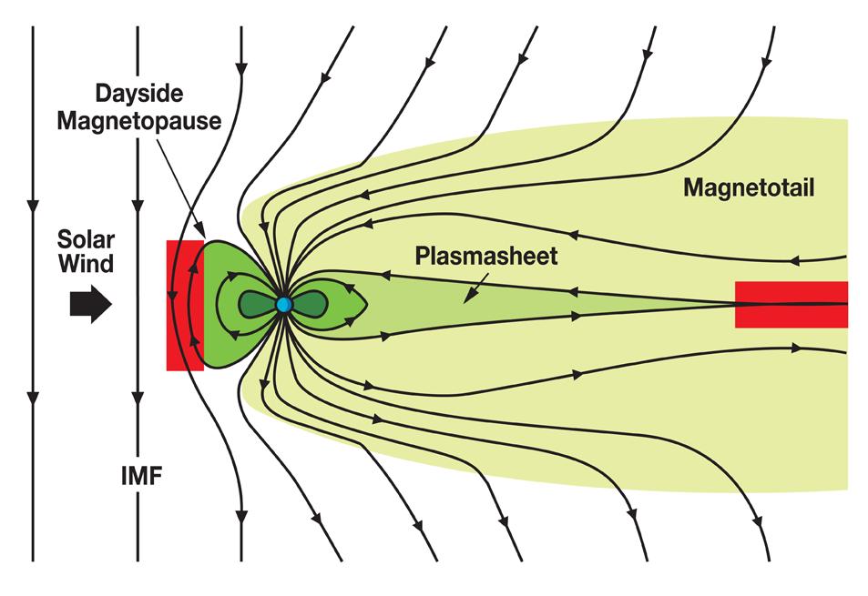
47
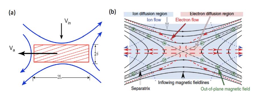
48
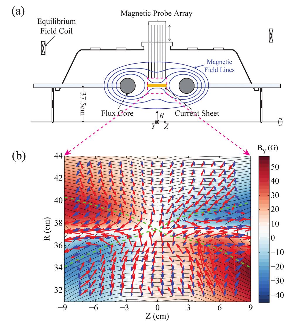
49
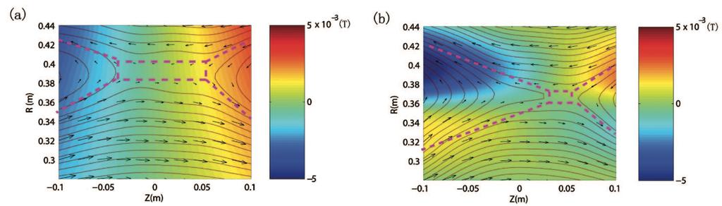
50
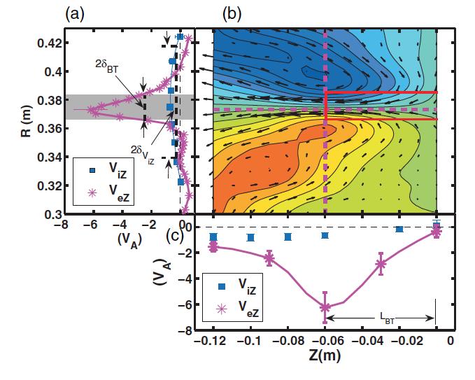
51
52 E Y (V/m) R (cm) E rec (V e xb) Y η S J Y
53 a Magnetic Field Lines and Electron Flow Vectors b 3 D View of Fig.a 5 Z (cm) R (cm) R (cm) Z (cm) 1 5 Y (cm) 5 3 c 42 2 D Electron Temperature Profile T e (ev) d 42 j e E Profile (W/cm 3 ) 15 R (cm) R (cm) Z (cm) Z (cm)
54 (a) j e E (b) j e E (W/cm 3 ) R (cm) R (cm) Z (cm) Z (cm)
55 a 1 b Z (d i ) 1 2 X (d i ).5 1 X (d i ) c Z (d i ) J E x d 1 2 J E 1 Y (d i ) x X (d i ) X (d i ) Z (d i ) Z (d i )
56 Φ p (V) R (cm) Z (cm)
57 (a) R (cm) (1) X (2) X (3) X Z (cm) (W/cm 3 ) (b) f(v iz ) (1) (2) (3) v iz /v th
58 R (cm) Z (cm) 1 B Y (G)
.8±.4! Change of thermal energy!.17±.5! Energy loss rate (Conduction, neutrals).")
59 Magnetic energy inflow rate! 1.±.1! Magnetic energy outflow rate!.49±.5! Energy deposition rate to electrons!.18±.4! Energy deposition rate to ions!.37±.7! MHD component!.22±.2! Change of thermal energy!.14±.5! Change of flow energy!.7±.2! Hall-field component!.27±.3! Energy loss rate (Conduction, radiation).8±.4! Change of thermal energy!.17±.5! Energy loss rate (Conduction, neutrals).16!
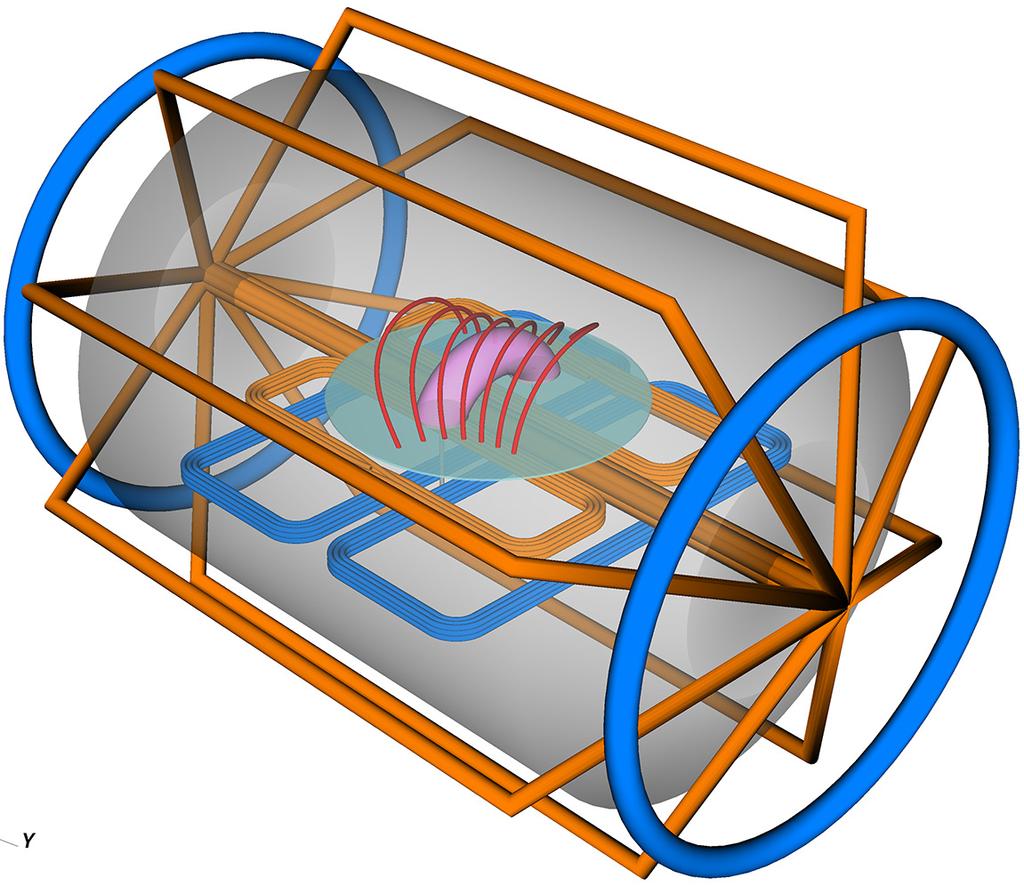
60
61 5. Eruptive Failed torus 1.5 Potential field decay inde, n Instability amplitude, δz /x f.3 Failed kink Stable Edge safety factor, q a
 153884 15441 z (cm) 6 5 4")
 15441, t = 25 µs.5.5 2 2 Current density (MA m 2 ) Magnetic field (G)")
62 a Poloidal cross-section Height, z (cm) Height, z (cm) b c Color = ê y B P Eruptive Failed torus Time (µs) z (cm) Vectors = B P, Color = J T d 1 1 y (cm) e Vectors = J P, Color = B Ti 1 1 y (cm) 15441, t = 25 µs Current density (MA m 2 ) Magnetic field (G)
63 t = 24. µs t = µs t = µs t = µs t = µs t = 256. µs 6 B P J T B P J T B P J T B P J T B P J T B P J T.6 z (cm) Current density (MA m -2 ) B Ti B Ti B Ti B Ti B Ti B Ti 2 z (cm) Magnetic field (G) y (cm) 1 1 y (cm) 1 1 y (cm) 1 1 y (cm) 1 1 y (cm) 1 1 y (cm)
 5 4 3 2 1.4.2.2.4.6 Current density (MA m -2 ) 6")
64 t = µs t = µs t = 244. µs t = µs t = µs t = µs 6 B P J T B P J T B P J T B P J T B P J T B P J T.6 z (cm) Current density (MA m -2 ) B Ti B Ti B Ti B Ti B Ti B Ti 2 z (cm) Magnetic field (G) y (cm) 1 1 y (cm) 1 1 y (cm) 1 1 y (cm) 1 1 y (cm) 1 1 y (cm)
65 Vertical force (N/cm) Height, δz (cm) 15 a b 1.5 F h F s F t + F s Magnetic Field (G) Current density (MA m -2 ).5 c d J T Paramagnetic B Ti Time (µs) Minor radius (cm)
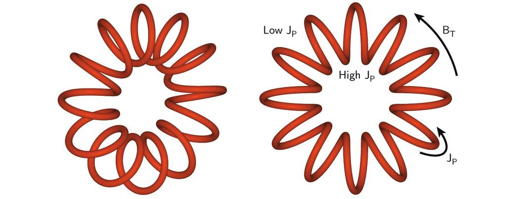
66
Magnetic Reconnection in Laboratory, Astrophysical, and Space Plasmas
 Magnetic Reconnection in Laboratory, Astrophysical, and Space Plasmas Nick Murphy Harvard-Smithsonian Center for Astrophysics namurphy@cfa.harvard.edu http://www.cfa.harvard.edu/ namurphy/ November 18,
November 2, Monday. 17. Magnetic Energy Release
 November, Monday 17. Magnetic Energy Release Magnetic Energy Release 1. Solar Energetic Phenomena. Energy Equation 3. Two Types of Magnetic Energy Release 4. Rapid Dissipation: Sweet s Mechanism 5. Petschek
Special topic JPFR article Prospects of Research on Innovative Concepts in ITER Era contribution by M. Brown Section 5.2.2
 Special topic JPFR article Prospects of Research on Innovative Concepts in ITER Era contribution by M. Brown Section 5.2.2 5.2.2 Dynamo and Reconnection Research: Overview: Spheromaks undergo a relaxation
Magnetic Reconnection: explosions in space and astrophysical plasma. J. F. Drake University of Maryland
 Magnetic Reconnection: explosions in space and astrophysical plasma J. F. Drake University of Maryland Magnetic Energy Dissipation in the Universe The conversion of magnetic energy to heat and high speed
Magnetic Reconnection: Recent Developments and Future Challenges
 Magnetic Reconnection: Recent Developments and Future Challenges A. Bhattacharjee Center for Integrated Computation and Analysis of Reconnection and Turbulence (CICART) Space Science Center, University
SW103: Lecture 2. Magnetohydrodynamics and MHD models
 SW103: Lecture 2 Magnetohydrodynamics and MHD models Scale sizes in the Solar Terrestrial System: or why we use MagnetoHydroDynamics Sun-Earth distance = 1 Astronomical Unit (AU) 200 R Sun 20,000 R E 1
1 EX/P7-12. Transient and Intermittent Magnetic Reconnection in TS-3 / UTST Merging Startup Experiments
 1 EX/P7-12 Transient and Intermittent Magnetic Reconnection in TS-3 / UTST Merging Startup Experiments Y. Ono 1), R. Imazawa 1), H. Imanaka 1), T. Hayamizu 1), M. Inomoto 1), M. Sato 1), E. Kawamori 1),
Introduction to Plasma Physics
 Introduction to Plasma Physics Hartmut Zohm Max-Planck-Institut für Plasmaphysik 85748 Garching DPG Advanced Physics School The Physics of ITER Bad Honnef, 22.09.2014 A simplistic view on a Fusion Power
Magnetic Reconnection with Sweet-Parker Characteristics in. Two-dimensional Laboratory Plasmas. Abstract
 Magnetic Reconnection with Sweet-Parker Characteristics in Two-dimensional Laboratory Plasmas Hantao Ji, Masaaki Yamada, Scott Hsu, Russell Kulsrud, Troy Carter, and Sorin Zaharia Plasma Physics Laboratory,
Experimental Investigations of Magnetic Reconnection. J Egedal. MIT, PSFC, Cambridge, MA
 Experimental Investigations of Magnetic Reconnection J Egedal MIT, PSFC, Cambridge, MA Coronal Mass Ejections Movie from NASA s Solar Dynamics Observatory (SDO) Space Weather The Solar Wind affects the
Solar Flare. A solar flare is a sudden brightening of solar atmosphere (photosphere, chromosphere and corona)
") Solar Flares Solar Flare A solar flare is a sudden brightening of solar atmosphere (photosphere, chromosphere and corona) Flares release 1027-1032 ergs energy in tens of minutes. (Note: one H-bomb: 10
Solar Flares Solar Flare A solar flare is a sudden brightening of solar atmosphere (photosphere, chromosphere and corona) Flares release 1027-1032 ergs energy in tens of minutes. (Note: one H-bomb: 10
Reduced MHD. Nick Murphy. Harvard-Smithsonian Center for Astrophysics. Astronomy 253: Plasma Astrophysics. February 19, 2014
 Reduced MHD Nick Murphy Harvard-Smithsonian Center for Astrophysics Astronomy 253: Plasma Astrophysics February 19, 2014 These lecture notes are largely based on Lectures in Magnetohydrodynamics by Dalton
Macroscopic plasma description
 Macroscopic plasma description Macroscopic plasma theories are fluid theories at different levels single fluid (magnetohydrodynamics MHD) two-fluid (multifluid, separate equations for electron and ion
Fluid equations, magnetohydrodynamics
 Fluid equations, magnetohydrodynamics Multi-fluid theory Equation of state Single-fluid theory Generalised Ohm s law Magnetic tension and plasma beta Stationarity and equilibria Validity of magnetohydrodynamics
Study of local reconnection physics in a laboratory plasma
 Earth Planets Space, 53, 539 545, 2001 Study of local reconnection physics in a laboratory plasma Hantao Ji, Troy Carter, Scott Hsu, and Masaaki Yamada Princeton Plasma Physics Laboratory, Princeton University,
Magnetic field reconnection is said to involve an ion diffusion region surrounding an
 The magnetic field reconnection site and dissipation region by P.L. Pritchett 1 and F.S. Mozer 2 1. Department of Physics and Astronomy, UCLA, Los Angeles, CA 90095-1547 2. Space Sciences Laboratory, University
Plasma Physics for Astrophysics
 - ' ' * ' Plasma Physics for Astrophysics RUSSELL M. KULSRUD PRINCETON UNIVERSITY E;RESS '. ' PRINCETON AND OXFORD,, ', V. List of Figures Foreword by John N. Bahcall Preface Chapter 1. Introduction 1
Physical mechanism of spontaneous fast reconnection evolution
 Earth Planets Space, 53, 431 437, 2001 Physical mechanism of spontaneous fast reconnection evolution M. Ugai Department of Computer Science, Faculty of Engineering, Ehime University, Matsuyama 790-8577,
3D Reconnection of Weakly Stochastic Magnetic Field and its Implications
 3D Reconnection of Weakly Stochastic Magnetic Field and its Implications Alex Lazarian Astronomy Department and Center for Magnetic Self- Organization in Astrophysical and Laboratory Plasmas Collaboration:
MHD RELATED TO 2-FLUID THEORY, KINETIC THEORY AND MAGANETIC RECONNECTION
 MHD RELATED TO 2-FLUID THEORY, KINETIC THEORY AND MAGANETIC RECONNECTION Marty Goldman University of Colorado Spring 2017 Physics 5150 Issues 2 How is MHD related to 2-fluid theory Level of MHD depends
MAGNETIC RECONNECTION: SWEET-PARKER VERSUS PETSCHEK
 MAGNETIC RECONNECTION: SWEET-PARKER VERSUS PETSCHEK RUSSELL M. KULSRUD Princeton Plasma Physics Laboratory rmk@pppl.gov arxiv:astro-ph/775v1 6 Jul 2 February 1, 28 Abstract The two theories for magnetic
Two Fluid Dynamo and Edge-Resonant m=0 Tearing Instability in Reversed Field Pinch
 1 Two Fluid Dynamo and Edge-Resonant m= Tearing Instability in Reversed Field Pinch V.V. Mirnov 1), C.C.Hegna 1), S.C. Prager 1), C.R.Sovinec 1), and H.Tian 1) 1) The University of Wisconsin-Madison, Madison,
Mechanisms for particle heating in flares
 Mechanisms for particle heating in flares J. F. Drake University of Maryland J. T. Dahlin University of Maryland M. Swisdak University of Maryland C. Haggerty University of Delaware M. A. Shay University
Plasma spectroscopy when there is magnetic reconnection associated with Rayleigh-Taylor instability in the Caltech spheromak jet experiment
 Plasma spectroscopy when there is magnetic reconnection associated with Rayleigh-Taylor instability in the Caltech spheromak jet experiment KB Chai Korea Atomic Energy Research Institute/Caltech Paul M.
Magnetic reconnection with Sweet-Parker characteristics in two-dimensional laboratory plasmas*
 PHYSICS OF PLASMAS VOLUME 6, NUMBER 5 MAY 1999 Magnetic reconnection with Sweet-Parker characteristics in two-dimensional laboratory plasmas* Hantao Ji,,a) Masaaki Yamada, Scott Hsu, Russell Kulsrud, Troy
Magnetic Reconnection: dynamics and particle acceleration J. F. Drake University of Maryland
 Magnetic Reconnection: dynamics and particle acceleration J. F. Drake University of Maryland M. Swisdak University of Maryland T. Phan UC Berkeley E. Quatert UC Berkeley R. Lin UC Berkeley S. Lepri U Michican
Space Physics. An Introduction to Plasmas and Particles in the Heliosphere and Magnetospheres. May-Britt Kallenrode. Springer
 May-Britt Kallenrode Space Physics An Introduction to Plasmas and Particles in the Heliosphere and Magnetospheres With 170 Figures, 9 Tables, Numerous Exercises and Problems Springer Contents 1. Introduction
Simple examples of MHD equilibria
 Department of Physics Seminar. grade: Nuclear engineering Simple examples of MHD equilibria Author: Ingrid Vavtar Mentor: prof. ddr. Tomaž Gyergyek Ljubljana, 017 Summary: In this seminar paper I will
Scaling of Magnetic Reconnection in Collisional and Kinetic Regimes
 Scaling of Magnetic Reconnection in Collisional and Kinetic Regimes William Daughton Los Alamos National Laboratory Collaborators: Vadim Roytershteyn, Brian Albright H. Karimabadi, Lin Yin & Kevin Bowers
Asymmetric Magnetic Reconnection in Coronal Mass Ejection Current Sheets
 Asymmetric Magnetic Reconnection in Coronal Mass Ejection Current Sheets Nicholas Murphy, 1 Mari Paz Miralles, 1 Crystal Pope, 1,2 John Raymond, 1 Kathy Reeves, 1 Dan Seaton, 3 & David Webb 4 1 Harvard-Smithsonian
Magnetic Reconnection Controlled by Multi-Hierarchy Physics in an Open System
 Magnetic Reconnection Controlled by Multi-Hierarchy Physics in an Open System Ritoku HORIUCHI 1,2), Shunsuke USAMI 1), Hiroaki OHTANI 1,2) and Toseo MORITAKA 3) 1) National Institute for Fusion Science,
Space Plasma Physics Thomas Wiegelmann, 2012
 Space Plasma Physics Thomas Wiegelmann, 2012 1. Basic Plasma Physics concepts 2. Overview about solar system plasmas Plasma Models 3. Single particle motion, Test particle model 4. Statistic description
The Virial Theorem, MHD Equilibria, and Force-Free Fields
 The Virial Theorem, MHD Equilibria, and Force-Free Fields Nick Murphy Harvard-Smithsonian Center for Astrophysics Astronomy 253: Plasma Astrophysics February 10 12, 2014 These lecture notes are largely
Magnetic reconnection in coronal plasmas
 UW, 28 May, 2010 p.1/17 Magnetic reconnection in coronal plasmas I.J.D Craig Department of Mathematics University of Waikato Hamilton New Zealand UW, 28 May, 2010 p.2/17 Why reconnection? Reconnection
Hybrid Simulations: Numerical Details and Current Applications
 Hybrid Simulations: Numerical Details and Current Applications Dietmar Krauss-Varban and numerous collaborators Space Sciences Laboratory, UC Berkeley, USA Boulder, 07/25/2008 Content 1. Heliospheric/Space
Heating and current drive: Radio Frequency
 Heating and current drive: Radio Frequency Dr Ben Dudson Department of Physics, University of York Heslington, York YO10 5DD, UK 13 th February 2012 Dr Ben Dudson Magnetic Confinement Fusion (1 of 26)
Asymmetric Magnetic Reconnection and the Motion of Magnetic Null Points
 Asymmetric Magnetic Reconnection and the Motion of Magnetic Null Points Nick Murphy Harvard-Smithsonian Center for Astrophysics 10th Cambridge Workshop on Magnetic Reconnection Santa Fe, New Mexico September
Ideal Magnetohydrodynamics (MHD)
") Ideal Magnetohydrodynamics (MHD) Nick Murphy Harvard-Smithsonian Center for Astrophysics Astronomy 253: Plasma Astrophysics February 1, 2016 These lecture notes are largely based on Lectures in Magnetohydrodynamics
Ideal Magnetohydrodynamics (MHD) Nick Murphy Harvard-Smithsonian Center for Astrophysics Astronomy 253: Plasma Astrophysics February 1, 2016 These lecture notes are largely based on Lectures in Magnetohydrodynamics
Magnetic Reconnection
 Magnetic Reconnection J. Egedal In collaboration with Joe Olson, Cary Forest and the MPDX team UW-Madison, WI Les Houches, March, 2015 Madison Plasma Dynamo experiment 2 Key new hardware for TREX Cylindrical
Experimental Study of Hall Effect on a Formation Process of an FRC by Counter-Helicity Spheromak Merging in TS-4 )
") Experimental Study of Hall Effect on a Formation Process of an FRC by Counter-Helicity Spheromak Merging in TS-4 ) Yasuhiro KAMINOU, Michiaki INOMOTO and Yasushi ONO Graduate School of Engineering, The
Experimental Study of Hall Effect on a Formation Process of an FRC by Counter-Helicity Spheromak Merging in TS-4 ) Yasuhiro KAMINOU, Michiaki INOMOTO and Yasushi ONO Graduate School of Engineering, The
Particle acceleration in stressed coronal magnetic fields
 To be submitted to ApJ Letters Particle acceleration in stressed coronal magnetic fields R. Turkmani 1,L.Vlahos 2, K. Galsgaard 3,P.J.Cargill 1 and H. Isliker 2 ABSTRACT This letter presents an analysis
ブラックホール磁気圏での 磁気リコネクションの数値計算 熊本大学 小出眞路 RKKコンピュー 森野了悟 ターサービス(株) BHmag2012,名古屋大学,
 BHmag2012,名古屋大学,") RKK ( ) BHmag2012,, 2012.2.29 Outline Motivation and basis: Magnetic reconnection around astrophysical black holes Standard equations of resistive GRMHD Test calculations of resistive GRMHD A simulation
RKK ( ) BHmag2012,, 2012.2.29 Outline Motivation and basis: Magnetic reconnection around astrophysical black holes Standard equations of resistive GRMHD Test calculations of resistive GRMHD A simulation
B.V. Gudiksen. 1. Introduction. Mem. S.A.It. Vol. 75, 282 c SAIt 2007 Memorie della
 Mem. S.A.It. Vol. 75, 282 c SAIt 2007 Memorie della À Ø Ò Ø ËÓÐ Ö ÓÖÓÒ B.V. Gudiksen Institute of Theoretical Astrophysics, University of Oslo, Norway e-mail:boris@astro.uio.no Abstract. The heating mechanism
Formation and Long Term Evolution of an Externally Driven Magnetic Island in Rotating Plasmas )
") Formation and Long Term Evolution of an Externally Driven Magnetic Island in Rotating Plasmas ) Yasutomo ISHII and Andrei SMOLYAKOV 1) Japan Atomic Energy Agency, Ibaraki 311-0102, Japan 1) University
Formation and Long Term Evolution of an Externally Driven Magnetic Island in Rotating Plasmas ) Yasutomo ISHII and Andrei SMOLYAKOV 1) Japan Atomic Energy Agency, Ibaraki 311-0102, Japan 1) University
1 Energy dissipation in astrophysical plasmas
 1 1 Energy dissipation in astrophysical plasmas The following presentation should give a summary of possible mechanisms, that can give rise to temperatures in astrophysical plasmas. It will be classified
Dissipation Mechanism in 3D Magnetic Reconnection
 Dissipation Mechanism in 3D Magnetic Reconnection Keizo Fujimoto Computational Astrophysics Laboratory, RIKEN Reconnection (in the Earth Magnetosphere) Coroniti [1985] 10 km 10 5 km 10 3 km Can induce
Asymmetric Magnetic Reconnection in the Solar Atmosphere
 Asymmetric Magnetic Reconnection in the Solar Atmosphere Nick Murphy Harvard-Smithsonian Center for Astrophysics November 1, 2013 MIT PSFC Seminar Collaborators and Co-Conspirators: John Raymond, Mari
Week 8: Stellar winds So far, we have been discussing stars as though they have constant masses throughout their lifetimes. On the other hand, toward
 Week 8: Stellar winds So far, we have been discussing stars as though they have constant masses throughout their lifetimes. On the other hand, toward the end of the discussion of what happens for post-main
MAGNETIC NOZZLE PLASMA EXHAUST SIMULATION FOR THE VASIMR ADVANCED PROPULSION CONCEPT
 MAGNETIC NOZZLE PLASMA EXHAUST SIMULATION FOR THE VASIMR ADVANCED PROPULSION CONCEPT ABSTRACT A. G. Tarditi and J. V. Shebalin Advanced Space Propulsion Laboratory NASA Johnson Space Center Houston, TX
Particle acceleration during 2D and 3D magnetic reconnection
 Particle acceleration during 2D and 3D magnetic reconnection J. Dahlin University of Maryland J. F. Drake University of Maryland M. Swisdak University of Maryland Astrophysical reconnection Solar and stellar
Flow and dynamo measurements in the HIST double pulsing CHI experiment
 Innovative Confinement Concepts (ICC) & US-Japan Compact Torus (CT) Plasma Workshop August 16-19, 211, Seattle, Washington HIST Flow and dynamo measurements in the HIST double pulsing CHI experiment M.
Fast compression of a current sheet during externally driven magnetic reconnection
 Earth Planets Space, 53, 521 526, 2001 Fast compression of a current sheet during externally driven magnetic reconnection Y. Ono, M. Inomoto, Y. Ueda, T. Matsuyama, and Y. Murata High Temperature Plasma
Magnetic reconnection, merging flux ropes, 3D effects in RSX
 Magnetic reconnection, merging flux ropes, 3D effects in RSX T. Intrator P-24 I. Furno, E. Hemsing, S. Hsu, + many students G.Lapenta, P.Ricci T-15 Plasma Theory Second Workshop on Thin Current Sheets
Solar-Wind/Magnetosphere Coupling
 Solar-Wind/Magnetosphere Coupling Joe Borovsky Space Science Institute --- University of Michigan 1. Get a feeling for how the coupling works 2. Get an understanding of how reconnection works 3. Look at
MHD Flow Field and Momentum Transfer Process of Magneto-Plasma Sail
 J. Plasma Fusion Res. SERIES, Vol. 8 (2009) MHD Flow Field and Momentum Transfer Process of Magneto-Plasma Sail Hiroyuki NISHIDA, Ikkoh FUNAKI, Yoshifumi INATANI 1) and Kanya KUSANO 2) University of Tokyo,
Magnetic Reconnection in Space Plasmas
 Magnetic Reconnection in Space Plasmas Lin-Ni Hau et al. Institute of Space Science Department of Physics National Central University, Taiwan R.O.C. EANAM, 2012.10.31 Contents Introduction Some highlights
arxiv: v2 [astro-ph.he] 11 Dec 2015
![arxiv: v2 [astro-ph.he] 11 Dec 2015](/thumbs/82/85900018.jpg "arxiv: v2 [astro-ph.he] 11 Dec 2015") Creation of Magnetized Jet Using a Ring of Laser Beams arxiv:1409.4273v2 [astro-ph.he] 11 Dec 2015 Wen Fu a, Edison P. Liang a, Petros Tzeferacos b, Donald Q. Lamb b a Department of Physics and Astronomy,
Creation of Magnetized Jet Using a Ring of Laser Beams arxiv:1409.4273v2 [astro-ph.he] 11 Dec 2015 Wen Fu a, Edison P. Liang a, Petros Tzeferacos b, Donald Q. Lamb b a Department of Physics and Astronomy,
MHD SIMULATIONS IN PLASMA PHYSICS
 MHD SIMULATIONS IN PLASMA PHYSICS P. Jelínek 1,2, M. Bárta 3 1 University of South Bohemia, Department of Physics, Jeronýmova 10, 371 15 České Budějovice 2 Charles University, Faculty of Mathematics and
Transition From Single Fluid To Pure Electron MHD Regime Of Tearing Instability
 Transition From Single Fluid To Pure Electron MHD Regime Of Tearing Instability V.V.Mirnov, C.C.Hegna, S.C.Prager APS DPP Meeting, October 27-31, 2003, Albuquerque NM Abstract In the most general case,
Asymmetric Magnetic Reconnection in the Solar Atmosphere
 Asymmetric Magnetic Reconnection in the Solar Atmosphere Nick Murphy Harvard-Smithsonian Center for Astrophysics October 23, 2013 NASA Goddard Space Flight Center Collaborators and Co-Conspirators: John
Magnetic Reconnection
 Magnetic Reconnection? On small scale-lengths (i.e. at sharp gradients), a diffusion region (physics unknown) can form where the magnetic field can diffuse through the plasma (i.e. a breakdown of the frozenin
The Physics of Fluids and Plasmas
 The Physics of Fluids and Plasmas An Introduction for Astrophysicists ARNAB RAI CHOUDHURI CAMBRIDGE UNIVERSITY PRESS Preface Acknowledgements xiii xvii Introduction 1 1. 3 1.1 Fluids and plasmas in the
Planetary Magnetospheres
 1 Planetary Magnetospheres Vytenis M. Vasyliūnas Max-Planck-Institut für Sonnensystemforschung Heliophysics Summer School: Year 4 July 28 August 4, 2010 Boulder, Colorado July 23, 2010 Figure 1: Schematic
8.2.2 Rudiments of the acceleration of particles
 430 The solar wind in the Universe intergalactic magnetic fields that these fields should not perturb them. Their arrival directions should thus point back to their sources in the sky, which does not appear
Beyond Ideal MHD. Nick Murphy. Harvard-Smithsonian Center for Astrophysics. Astronomy 253: Plasma Astrophysics. February 8, 2016
 Beyond Ideal MHD Nick Murphy Harvard-Smithsonian Center for Astrophysics Astronomy 253: Plasma Astrophysics February 8, 2016 These lecture notes are largely based on Plasma Physics for Astrophysics by
Two-fluid theory of collisionless magnetic reconnection
 Two-fluid theory of collisionless magnetic reconnection D. Biskamp and E. Schwarz Max-Planck-Institut für Plasmaphysik, 85748 Garching, Germany J. F. Drake Institute for Plasma Research, University of
Fast magnetic reconnection via jets and current micro-sheets
 Fast magnetic reconnection via jets and current micro-sheets P. G. Watson Center for Magnetic Reconnection Studies, Institute for Fusion Studies, Department of Physics, University of Texas at Austin, Austin,
0 Magnetically Confined Plasma
 0 Magnetically Confined Plasma 0.1 Particle Motion in Prescribed Fields The equation of motion for species s (= e, i) is written as d v ( s m s dt = q s E + vs B). The motion in a constant magnetic field
Direct drive by cyclotron heating can explain spontaneous rotation in tokamaks
 Direct drive by cyclotron heating can explain spontaneous rotation in tokamaks J. W. Van Dam and L.-J. Zheng Institute for Fusion Studies University of Texas at Austin 12th US-EU Transport Task Force Annual
KINETIC DESCRIPTION OF MAGNETIZED TECHNOLOGICAL PLASMAS
 KINETIC DESCRIPTION OF MAGNETIZED TECHNOLOGICAL PLASMAS Ralf Peter Brinkmann, Dennis Krüger Fakultät für Elektrotechnik und Informationstechnik Lehrstuhl für Theoretische Elektrotechnik Magnetized low
Flow dynamics and plasma heating of spheromaks in SSX
 Flow dynamics and plasma heating of spheromaks in SSX M. R. Brown and C. D. Cothran, D. Cohen, J. Horwitz, and V. Chaplin Department of Physics and Astronomy Center for Magnetic Self Organization Swarthmore
Asymmetric Magnetic Reconnection in the Solar Atmosphere
 Asymmetric Magnetic Reconnection in the Solar Atmosphere Nick Murphy Harvard-Smithsonian Center for Astrophysics Pre-Hurricane NIMROD Team Meeting Providence, Rhode Island October 27, 2012 Collaborators:
26. Non-linear effects in plasma
 Phys780: Plasma Physics Lecture 26. Non-linear effects. Collisionless shocks.. 1 26. Non-linear effects in plasma Collisionless shocks ([1], p.405-421, [6], p.237-245, 249-254; [4], p.429-440) Collisionless
Turbulence and Transport The Secrets of Magnetic Confinement
 Turbulence and Transport The Secrets of Magnetic Confinement Presented by Martin Greenwald MIT Plasma Science & Fusion Center IAP January 2005 FUSION REACTIONS POWER THE STARS AND PRODUCE THE ELEMENTS
Self-organization of Reconnecting Plasmas to a Marginally Collisionless State. Shinsuke Imada (Nagoya Univ., STEL)
") Self-organization of Reconnecting Plasmas to a Marginally Collisionless State Shinsuke Imada (Nagoya Univ., STEL) Introduction The role of Magnetic reconnection Solar Flare Coronal heating, micro/nano-flare
Self-organization of Reconnecting Plasmas to a Marginally Collisionless State Shinsuke Imada (Nagoya Univ., STEL) Introduction The role of Magnetic reconnection Solar Flare Coronal heating, micro/nano-flare
Crab flares - explosive Reconnection Events in the Nebula
 Crab flares - explosive Reconnection Events in the Nebula Maxim Lyutikov (Purdue) in collaboration with Sergey Komissarov (Leeds) Lorenzo Sironi (Columbia) Oliver Porth (Frankfurt) - ApJ 2017; - JPP, 2017abc
Conservation Laws in Ideal MHD
 Conservation Laws in Ideal MHD Nick Murphy Harvard-Smithsonian Center for Astrophysics Astronomy 253: Plasma Astrophysics February 3, 2016 These lecture notes are largely based on Plasma Physics for Astrophysics
Why study plasma astrophysics?
 Why study plasma astrophysics? Nick Murphy and Xuening Bai Harvard-Smithsonian Center for Astrophysics Astronomy 253: Plasma Astrophysics January 25, 2016 Today s plan Definition of a plasma Plasma astrophysics:
Plasma heating and asymmetric reconnection in CMEs
 Plasma heating and asymmetric reconnection in CMEs Harvard-Smithsonian Center for Astrophysics September 28, 2010 Collaborators: John Raymond, Kelly Korreck, Carl Sovinec, Paul Cassak, Jun Lin, Chengcai
From Sun to Earth and beyond, The plasma universe
 From Sun to Earth and beyond, The plasma universe Philippe LOUARN CESR - Toulouse Study of the hot solar system Sun Magnetospheres Solar Wind Planetary environments Heliosphere a science of strongly coupled
High energy particles from the Sun. Arto Sandroos Sun-Earth connections
 High energy particles from the Sun Arto Sandroos Sun-Earth connections 25.1.2006 Background In addition to the solar wind, there are also particles with higher energies emerging from the Sun. First observations
Thrust Evaluation of Magneto Plasma Sail Injecting Thermal Plasma by using 3D Hybrid PIC Code
 Thrust Evaluation of Magneto Plasma Sail Injecting Thermal Plasma by using 3D Hybrid PIC Code IEPC-2015-462p /ISTS-2015-b-462p Presented at Joint Conference of 30th International Symposium on Space Technology
Plasmas as fluids. S.M.Lea. January 2007
 Plasmas as fluids S.M.Lea January 2007 So far we have considered a plasma as a set of non intereacting particles, each following its own path in the electric and magnetic fields. Now we want to consider
Asymmetry and thermal effects due to parallel motion of electrons in collisionless magnetic reconnection
 Asymmetry and thermal effects due to parallel motion of electrons in collisionless magnetic reconnection Motohiko Tanaka a) Research Laboratory of Electronics and Department of Physics, Massachusetts Institute
Experimental studies of magnetic reconnection*
 PHYSICS OF PLASMAS VOLUME 6, NUMBER 5 MAY 1999 Experimental studies of magnetic reconnection* M. R. Brown Department of Physics and Astronomy, Swarthmore College, Swarthmore, Pennsylvania 19081-1397 Received
Solar-Terrestrial Physics. The Sun s Atmosphere, Solar Wind, and the Sun-Earth Connection
 Week 2 Lecture Notes Solar-Terrestrial Physics The Sun s Atmosphere, Solar Wind, and the Sun-Earth Connection www.cac.cornell.edu/~slantz The Solar Corona is the Sun s Extended Atmosphere Scattered light
MAGNETOHYDRODYNAMICS - 2 (Sheffield, Sept 2003) Eric Priest. St Andrews
 Eric Priest. St Andrews") MAGNETOHYDRODYNAMICS - 2 (Sheffield, Sept 2003) Eric Priest St Andrews CONTENTS - Lecture 2 1. Introduction 2. Flux Tubes *Examples 3. Fundamental Equations 4. Induction Equation *Examples 5. Equation
MAGNETOHYDRODYNAMICS - 2 (Sheffield, Sept 2003) Eric Priest St Andrews CONTENTS - Lecture 2 1. Introduction 2. Flux Tubes *Examples 3. Fundamental Equations 4. Induction Equation *Examples 5. Equation
Finite-time singularity formation at a magnetic neutral line in Hall magnetohydrodynamics
 Finite-time singularity formation at a magnetic neutral line in Hall magnetohydrodynamics Yuri E. Litvinenko, Liam C. McMahon Department of Mathematics, University of Waikato, P. B. 3105, Hamilton, New
Magnetic Reconnection
 Magnetic Reconnection Prof. Christopher J. Owen UCL/Mullard Space Science Laboratory, Holmbury St. Mary, Dorking, Surrey, RH5 6NT, United Kingdom c.owen@ucl.ac.uk 9 th September 2015 Outline MHD, topology
Collisions and transport phenomena
 Collisions and transport phenomena Collisions in partly and fully ionized plasmas Typical collision parameters Conductivity and transport coefficients Conductivity tensor Formation of the ionosphere and
Prof. dr. A. Achterberg, Astronomical Dept., IMAPP, Radboud Universiteit
 Prof. dr. A. Achterberg, Astronomical Dept., IMAPP, Radboud Universiteit Rough breakdown of MHD shocks Jump conditions: flux in = flux out mass flux: ρv n magnetic flux: B n Normal momentum flux: ρv n
Magneto-Fluid Coupling in Dynamic Finely Structured Solar Atmosphere Theory and Simulation
 Magneto-Fluid Coupling in Dynamic Finely Structured Solar Atmosphere Theory and Simulation Nana L. Shatashvili 1,2, In collaboration with S. M. Mahajan 2, Z. Yoshida 3 R. Miklaszewski 4 & K.I. Nikol skaya
The hall effect in magnetic reconnection: Hybrid versus Hall-less hybrid simulations
 Click Here for Full Article GEOPHYSICAL RESEARCH LETTERS, VOL. 36, L07107, doi:10.1029/2009gl037538, 2009 The hall effect in magnetic reconnection: Hybrid versus Hall-less hybrid simulations K. Malakit,
Creation and destruction of magnetic fields
 HAO/NCAR July 30 2007 Magnetic fields in the Universe Earth Magnetic field present for 3.5 10 9 years, much longer than Ohmic decay time ( 10 4 years) Strong variability on shorter time scales (10 3 years)
MHD Simulation of Solar Chromospheric Evaporation Jets in the Oblique Coronal Magnetic Field
 MHD Simulation of Solar Chromospheric Evaporation Jets in the Oblique Coronal Magnetic Field Y. Matsui, T. Yokoyama, H. Hotta and T. Saito Department of Earth and Planetary Science, University of Tokyo,
Magnetic Reconnection in ICME Sheath
 WDS'11 Proceedings of Contributed Papers, Part II, 14 18, 2011. ISBN 978-80-7378-185-9 MATFYZPRESS Magnetic Reconnection in ICME Sheath J. Enzl, L. Prech, K. Grygorov, A. Lynnyk Charles University, Faculty
PROBLEM 1 (15 points) In a Cartesian coordinate system, assume the magnetic flux density
 In a Cartesian coordinate system, assume the magnetic flux density") PROBLEM 1 (15 points) In a Cartesian coordinate system, assume the magnetic flux density varies as ( ) where is a constant, is the unit vector in x direction. a) Sketch the magnetic flux density and the
PROBLEM 1 (15 points) In a Cartesian coordinate system, assume the magnetic flux density varies as ( ) where is a constant, is the unit vector in x direction. a) Sketch the magnetic flux density and the
arxiv: v2 [physics.plasm-ph] 2 May 2018
![arxiv: v2 [physics.plasm-ph] 2 May 2018](/thumbs/90/102437899.jpg "arxiv: v2 [physics.plasm-ph] 2 May 2018") Drift Turbulence, Particle Transport, and Anomalous Dissipation at the Reconnecting Magnetopause A. Le, 1 W. Daughton, 1 O. Ohia, 1 L.-J. Chen, 2 Y.-H. arxiv:1802.10205v2 [physics.plasm-ph] 2 May 2018
Drift Turbulence, Particle Transport, and Anomalous Dissipation at the Reconnecting Magnetopause A. Le, 1 W. Daughton, 1 O. Ohia, 1 L.-J. Chen, 2 Y.-H. arxiv:1802.10205v2 [physics.plasm-ph] 2 May 2018
The Physics of Collisionless Accretion Flows. Eliot Quataert (UC Berkeley)
") The Physics of Collisionless Accretion Flows Eliot Quataert (UC Berkeley) Accretion Disks: Physical Picture Simple Consequences of Mass, Momentum, & Energy Conservation Matter Inspirals on Approximately
The Physics of Collisionless Accretion Flows Eliot Quataert (UC Berkeley) Accretion Disks: Physical Picture Simple Consequences of Mass, Momentum, & Energy Conservation Matter Inspirals on Approximately
On the physics of shear flows in 3D geometry
 On the physics of shear flows in 3D geometry C. Hidalgo and M.A. Pedrosa Laboratorio Nacional de Fusión, EURATOM-CIEMAT, Madrid, Spain Recent experiments have shown the importance of multi-scale (long-range)