NON LINEAR BUCKLING OF COLUMNS Dr. Mereen Hassan Fahmi Technical College of Erbil
|
|
|
- Raymond Edwards
- 5 years ago
- Views:
Transcription
1 Abstract: NON LINEAR BUCKLING OF COLUMNS Dr. Mereen Hassan Fahmi Technical College of Erbil The geometric non-linear total potential energy equation is developed and extended to study the behavior of buckling and deflection beyond the bifurcation point and showing columns resistance beyond the Euler load. Three types of boundary conditions are studied (pin ended, fixed ended and cantilever). The equation of non-linear total potential energy is solved by exact method (closed form solution) and compared with other approximated methods (Rayleigh- Ritz, Koiter s theory and non-linear finite difference method). The agreement is found quite enough and satisfactory for most situations of practical cases. Key words: Bifurcation, Buckling, Columns, Finite difference method, Koiter s theory, nonlinear buckling and Rayleigh- Ritz method.. :.(Euler load ) (bifurcation point).( ) Rayleigh- Ritz, ) ( Koiter s theory and non-linear finite difference method. Received 17 th June 2004 Accepted 14 th Agust
2 Al-Rafidain Engineering Vol.14 No Notations: E: Modulus of Elasticity. I: Moment of inertia. L: Length of the member. P: Longitudinal axial load. P E : Euler load. s: Non-linear longitudinal coordinate. u: Longitudinal displacement. w: Transverse deflection. w max : Maximum deflection of the member. x: Longitudinal coordinate. : Total potential energy. : Deflection angle. : Curvature. Introduction: Stability of a body is that condition [1-7], if after some slight disturbance in the configuration the body returns to the original configuration, this condition is satisfied when there is no change in the total potential energy as the position is varied. In other word, the stability is obtained when the total potential energy in minimum condition and un-stability occurred at maximum total potential energy. For conservative systems, the equilibrium configuration is corresponding to the minimum total potential energy. Mathematically the stability problem is called an Eigen value problem, the critical load (buckling load) is an Eigen value load of the problem, and the deflection w(x) corresponding to the load is an Eigen function. Equilibrium method provides an infinite set of Eigen values (critical loads) where non-trivial configurations could satisfy the requirements of equilibrium and called modes of buckling. The lowest critical value is called the buckling load (Euler load). The equation of minimum total potential energy (functional) or general governing differential equation of the problem can be solved by various techniques such as (closed form or exact solution, finite element method) or approximated methods such as (Rayleigh-Ritz method, Galerkin s method and finite difference method). The bulk of buckling analysis that considered in most references is limited to the linearized Eigen value problems that define buckling load. In this study the geometrical non-linear total potential energy equation is developed for fixed ended and cantilever in addition to pin ended columns and solved by different methods. 1. Exact method (closed form solution). 2. An Intermediate method (Rayleigh- Ritz method). 3. Koiter s theory. 4. Non-linear finite difference method. 2
3 Derivation and solution: I-Exact method: The simplified functional for the total potential energy of columns can be written as following [1]: = EI/2 ( 2 w/ x 2 ) 2 dx P/2 ( w/ x ) 2 dx (1) Where ( 2 w/ x 2 ) represent the curvature ( ) in linear case, but in case of geometrical non-linear bending, the exact non-linear curvature expressed as below as given in ref. [1]: = ( / s ) = ( 2 w/ x 2 ) / [1 + ( w/ x ) 2 ] 3/2 Another form of curvature can be used in term of ( w/ s) as below: = ( / s ) = ( 2 w/ s 2 ) / [1 ( w/ s ) 2 ] 1/ (2) And the term [1/2 ( w/ x ) 2 dx ] represent the shortening of the member. L= [ L - cos( ) ds ] The functional in equation (1) for the geometrical non-linear case becomes: = EI/2 ( / s ) 2 ds P [ L - cos( ) ds ] (3) Minimizing ( ) with respect to ( ) and setting to zero ( / s=0) gives the following Euler Lagrange equation. EI ( 2 / s 2 ) + P sin( ) = (4) To simplify the above non-linear differential equation, multiply by ( / s) and rewrite in another form: d/ds [ EI/2 ( / s) 2 - P cos( ) ] = (5) Integrate the above equation directly to get: EI/2 ( / s ) 2 = P cos( ) + C (6) For pin ended columns the boundary condition at the ends (x=0 and L) are ( / s= 0), this means that ( ) is constant at the ends and vary between (± ); where ( ) is the angle at the ends. For fixed ended columns, the variation of ( ) between (± ) occurred at (x=l/4 and x=3/4 L). By applying the boundary conditions; C1= - P cos( ) Hence: EI/2 ( / s ) 2 = P [cos( ) - cos( )] or / s = 2P/EI [cos( ) - cos( )] (7) Using cos( )=1-2 sin 2 ( /2) and cos( )=1-2 sin 2 ( /2) The above equation becomes: / s = 4P/EI [ sin 2 ( /2) - sin 2 ( /2) ] (8) By separating variables, the following integration is obtained as following: L= ds = EI/4P d / [sin 2 /2 sin 2 /2 ] 1/2 Due to symmetry of he deflection curve about the line (x=l/2) L= ds = EI/4P 2d / [sin 2 /2 sin 2 /2 ] 1/ (9) The above equation to be changed to another form, using change of variables as following: Let sin( /2) = sin( /2) sin( ) and = sin( /2) With some algebric manipulation, the above equation can be written in the following manner: 3
4 Al-Rafidain Engineering Vol.14 No L= EI/P 2d / [ 1 2 sin 2 ] 1/ (10) Where at ends for pin end column and at (x=l/4, x=3/4l) for fixed ended column = ± ; then = ± /2 Introducing of the linear Euler load (P E = 2 EI/L 2 ) for pin ended column and (P E = 4 2 EI/L 2 ) for fixed ended column, [1, 2 & 6], the above equation becomes: P/P E = 2/ d / [ 1 2 sin 2 ] 1/ (11) the integration limits vary from (0) to (L) for pin ended column while the limits vary from (L/4) to (3/4 L) for fixed ended column. Where P/P E is the ratio of nonlinear to linear buckling load (Euler load). The maximum buckling deflection (w max ) of the column is related with the ratio (P/P E ), for this purpose, use sin( ) = w/ s, accordingly, the Euler-Lagrange equation (4) can be written as follows: EI 2 / s 2 + P w/ s = (12) Integrate both sides and rearrange to get the following equation. w = - EI/P d /ds + C2 at the ends, w= 0 and / s = 0 Thus C2=0 Use equation (7) to replace ( / s), to get: w = - 2EI/P [ cos( ) cos( ) ] 1/2 At mid span, = 0 and w= w max w max = - 2EI/P [ 1 cos( ) ] 1/ (13) Introducing Euler load (P E ) and using some trigonometric identity, the above equation can be written in another form: w max /L = 2/ [sin( /2) / P/P E ] = 2/ ( / P/P E ) (14) The equation is same for pin ended and fixed ended column For cantilever column, the boundary conditions are different: At x= 0, = 0 and at x= L, = ; / s= 0 and Euler load = 2 EI/4L 2 Applying the above boundary conditions and introducing Euler load and using the same previous procedures, the final equation of the deflection becomes: w max /L = 4/ [ sin( /2) / P/P E ] = 4/ ( / P/P E } (15) Procedures of solution: - 1- For known value of (P/P E ), the value of [ = sin( /2)] is determined from equation (11), by trail and error method to satisfy the value of the integration to be equal to root of the ratio (P/P E ), using numeric integration method. 2- Use equation (14) or equation (15) to determine the value of (w max /L) for the known values of (P/P E ) and ( ) which determined from the previous step. 3- Repeat the procedures for other values of (P/P E ). 4- Tabulate the results and plot the relationship of (P/P E ) versus (w max /L). 4
5 II-An Intermediate theory (Rayleigh-Ritz method): - The total non-linear potential energy equation (3) and the non-linear curvature given in equation (2) are expressed in binomial expansion form using power series method as shown below [1]: - / s ( 2 w/ s 2 ) [1 + ½ ( w/ s) 2 ] (16) The term representing the shortening of the member (L - cos( ) ds), also expressed in form of ( w/ s), the final form of equation (3) becomes:- = EI/2 ( 2 w/ s 2 ) 2 [1+½( w/ s) 2 ] 2 ds P/2 [1+ ¼ ( w/ s) 2 ] ( w/ s) 2 ds ---(17) In small deflection theory, the term containing ( w/ s) 2 is being small in comparison with unity and replace (s) by (x) the form of equation (17) return to the classical theory for linear case. Applying Rayleigh-Ritz method and employing the Eigen functions that satisfy the boundary conditions of the column as in the following: - 1- Pin ended column:- The Eigen function is taken as the following. w(s) = A sin( s/l) (18) The assumed function is satisfies the boundary conditions at the ends At s=0 and L; w=0 Substitute in equation (17) and integrate the functional to find the final form of ( ) as shown: = EI 2 /4L [a 2 + ¼ a 4 + a 6 /32 P/P E (a 2 + 3/16 a 4 ) ] (19) Where a = A /L Extremizing of ( ) with respect of (a) to obtain: a /3 (1- ¾ P/P E ) a /3 (1- P/P E ) = (20) The above equation of 4 th order is solved by Newton-Raphson method to determine the value of (a) corresponding to the ratio (P/P E ), noting that (w max /L = a / ), then plot the relationship of (P/P E ) versus (w max /L). 2- Fixed ended column:- The suitable Eigen function which satisfy the boundary conditions of the two fixed ends can be taken as the following: - w(s) = A [1- cos(2 s/l)] (21) Following the same procedures as in pin- ended column, the final equation becomes: a 4 + 4/3 (1- ¾ P/P E ) a 2 + 2/3 (1- P/P E ) = (22) Where a = A /L and w max /L = 2 a / 3- Cantilever column:- The suitable Eigen function, which satisfies the boundary conditions, can be taken as the following. w(s) = A [1- cos( s/2l)] (23) 5
6 Al-Rafidain Engineering Vol.14 No The final equation becomes: a 4 + 4/3 (1- ¾ P/P E ) a 2 + 8/3 (1- P/P E ) = (24) Where a = A / 2L and w max /L = 2 a / III-Koiter s theory:- Consider (u) to be the axial displacement of the centerline of the column and (w) to be the transverse displacement of this center line [1]. dl = (1+ u/ x) 2 + ( w/ x) 2 dx (25) If the center line is assumed to be in-extensible, then dl=dx. Thus: (1+ u/ x) 2 + ( w/ x) 2 = (26) and u/ x = (1- ( w/ x) (27) let sin( )= w/ x and cos( ) = 1- sin( ) Take the non-linear curvature = ( 2 w/ x 2 ) / cos( ) = ( 2 w/ x 2 ) / [1 sin 2 ( )] Or = ( 2 w/ x 2 ) / [1-( w/ x) 2 ] (28) This is exactly same as equation (2) Using the above equations, the total potential energy equation can be written in the following form: - = EI/2 ( 2 w/ x 2 ) 2 / [1-( w/ x) 2 ]dx P [ (1- ( w/ x) 2-1] dx (29) Now use the dimensionless variables ( = x/l, = w/l, = P/P E ) Using power series expression and some algebric steps, the total potential energy can be expressed as the sum of a functional of order (2) and (4). P( ) = P 2 ( ) + P 4 ( ) P 2 ( ) = [( ) 2 2 ( ) 2 ] d (30) P 4 ( ) = [( ) 2 ( ) 2 2 /4 ( ) 4 ] d Where ( ) is a function of ( ). Equations (30) can be solved by substituting the suitable Eigen function that satisfy the boundary conditions of the column as in previous method. 1- Pin ended column:- The Eigen function is taken as [ = a sin( ) ], the resulting equation is: = 1+ 2 / 8 a 2 where a = w max /L and = P/P E The above equation can be written in the following form: - w max /L = 2 2 / (P/P E 1) 1/ (31) 2- Fixed ended column:- The Eigen function is taken as = a [1- cos(2 )], the resulting equation is: = [1+ ½ 2 a 2 ] / [1+ 3/8 2 a 2 ] where a = ½ (w max /L) w max /L = 2 / [(P/P E 1) / (1- ¾ P/P E )] 1/ (32) 6
7 3- Cantilever ended column:- The Eigen function is taken as = a [1- cos( /2)], the resulting equation is: = [1+ 2 /16 a 2 ] where a = w max /L w max /L = 4/ (P/P E 1) 1/ (33) IV-Non-linear finite difference method. The non-linear equation of bending of a member subjected to axial force can be written as the following: EI ( 2 w/ x 2 ) / [1-( w/ x) 2 ] = - P w Re-arrange the above equation to obtain: ( 2 w/ x 2 ) + P/EI [1-( w/ x) 2 ] w = (34) The equation expressed in finite difference form using central difference method. (w i+1 2 w i + w i-1 )/h 2 + P/EI [1-(w i+1 -w i-1 )/2h) 2 ] w i = 0 Or in simpler form: - w i+1 + A i w i + w i-1 = (35) Where A i = K [ [1-(w i+1 -w i-1 )/2h) 2 ] 2 and K = P h 2 / EI h = L/n, where (n) is the number of segments. Procedures of solution: 1-Assume a specified value of (w max /L). 2-Assume suitable Eigen function which satisfy the boundary condition of the column (pin ended, fixed ended and cantilever) as in previous methods. w = b sin( x/l) for pin ended column. w = b [1- cos(2 x/l) for fixed ended column. w = b [1- cos( x/2l) for cantilever column. 3-Use the assumed displacement function to find the initial values of (w i ) at all nodes to start the solution. 4-Substitute the known values of (w i ) in equation(35) to form a set of equations [A] {w} = 0 Where [A] is a coefficient matrix This equation is satisfied in two conditions i- Either {w} = 0 ; this gives trivial solution, or ii- Determinate of [A] = 0; this gives the Eigen value of the problem (K) 5-Find P = EI/h 2 K 6-Find the ratio (P/P E ) corresponding to the assumed value of (w max /L). 7-Repeat the above steps for other values of (w max /L). 8-Plot the relation of (w max /L) versus (P/P E ). 9-For fixed ended and cantilever columns, apply the same procedures using the suitable Eigen function and same changes in the formulation of the non-linear finite difference equation corresponding to the boundary conditions of the problem. 7
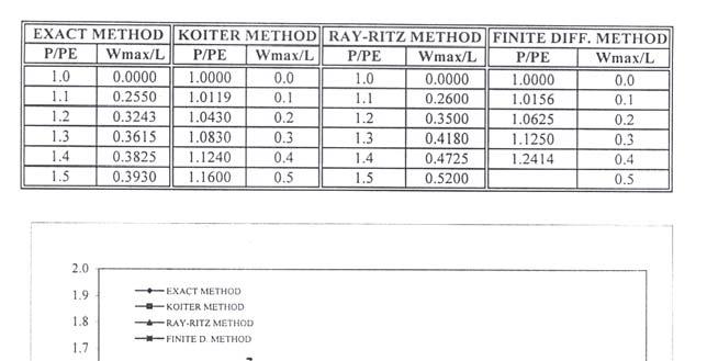
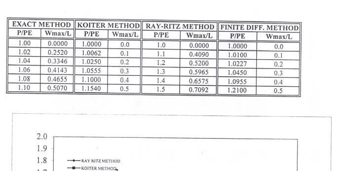
8 Al-Rafidain Engineering Vol.14 No Discussions and conclusions: The analysis of buckling that considered in most references is limited to the linearized Eigen value problems that define the buckling load. This research is a trail to study the geometric non-linear behavior of buckling beyond the buckling load for different types of columns (pin ended, fixed ended and cantilever). Derivations and results of exact theory are compared with different methods (Rayleigh-Ritz method, Koiter s theory and non-linear finite difference method). Fig(1) shows the comparison of exact solution for all column types and show that the curves are tangent to the horizontal axis at the load ratio (P/P E =1), and then the value of the deflection increased with increasing of (P/P E ). This point is called as the bifurcation point. This behavior means that the column can withstand even higher loads beyond the bifurcation point (buckling load). This situation is called post-buckling stability and the deformation regime beyond this point is called post-buckling regime. Figs(2,3 and 4) show the comparison of the result obtained from the different methods (Rayleigh-Ritz method, Koiter s theory and non-linear finite difference method) for pin ended, fixed ended and cantilever respectively. The results show that all solutions give the same behavior beyond the bifurcation point and agreement between the exact solution and these methods are quite good for (w max /L < 0.3) for pin ended and fixed ended columns and (w max /L < 0.4) for cantilever column, these limits are quite enough and more than satisfactory for most situations of practical cases. The variation of results of all methods in comparison with the exact method is about (±4%) for pin ended columns and (±5%) for fixed ended columns for (w max /L < 0.3) while (±4%) for cantilever columns for (w max /L < 0.4). Fig(1) shows that for constant value of (P/P E ), the cantilever column gives deflection value approximately twice than pin and fixed ended cloumns as shown below: at P/P E = 1.1 Type w max /L Ratio Pin ended column Fixed ended column Cantilever column And for constant deflection ratio (w max /L=0.4), the load ratio (P/P E =1.5) for pin and fixed ended columns while (P/P E =1.06) for cantilever column, this mean that cantilever column resist small extra load beyond the bifurcation point while pin and fixed ended resist much more up to (50%) beyond the bifurcation point. at w max /L = 0.4 Type P/P E Pin ended column 1.5 Fixed ended column 1.5 Cantilever column
9 Increasing of the deflection (w max /L) up to (0.25) cause increasing the load ratio (P/P E ) to (1.1), only (10%) increasing. But when (w max /L) increase to (0.4) the non-linear load ratio (P/P E ) jumped to the value (1.5) this reflect and explain the effect of large deflection (geometric non-linearity) on the resistance of the columns. The response and behavior of pin and fixed ended columns beyond the bifurcation point are similar while the cantilever columns showed lesser effect. References: 1-Dym, C.L. and Shames, I.H., Solid Mechanics A variational approaches, Mc-Graw Hill Inc., NewYork, USA, Washizu, K., Variational methods in Elasticity and Plasticity, Pergamon Press, 2 nd edition, Oxford, England, Timoshenko, S.P. and Goddier, J.N., Theory of Elasticity, Mc-Graw Hill Inc., 3 rd edition, Oden, J.T., Mechanics of Elastic Structures, Mc-Graw Hill Inc., NewYork, USA. 5-Majid, K.I., Non-Linear Structures, Butterworth & Co., Timoshenko, S.P. and Gere, J.M., Theory of Elastic Stability, Mc- Graw Hill Inc., 2 nd edition, Kitipornchoi, S., Hancock, G.J. and Bradford, M.A., Structural Stability and Design, A.A. Balkema, Rotterdam, Netherlands,
10 Al-Rafidain Engineering Vol.14 No
11 11
Unit 18 Other Issues In Buckling/Structural Instability
 Unit 18 Other Issues In Buckling/Structural Instability Readings: Rivello Timoshenko Jones 14.3, 14.5, 14.6, 14.7 (read these at least, others at your leisure ) Ch. 15, Ch. 16 Theory of Elastic Stability
Chapter 8 Supplement: Deflection in Beams Double Integration Method
 Chapter 8 Supplement: Deflection in Beams Double Integration Method 8.5 Beam Deflection Double Integration Method In this supplement, we describe the methods for determining the equation of the deflection
EMA 3702 Mechanics & Materials Science (Mechanics of Materials) Chapter 10 Columns
 Chapter 10 Columns") EMA 370 Mechanics & Materials Science (Mechanics of Materials) Chapter 10 Columns Columns Introduction Columns are vertical prismatic members subjected to compressive forces Goals: 1. Study the stability
EMA 370 Mechanics & Materials Science (Mechanics of Materials) Chapter 10 Columns Columns Introduction Columns are vertical prismatic members subjected to compressive forces Goals: 1. Study the stability
Flexural-Torsional Buckling of General Cold-Formed Steel Columns with Unequal Unbraced Lengths
 Proceedings of the Annual Stability Conference Structural Stability Research Council San Antonio, Texas, March 21-24, 2017 Flexural-Torsional Buckling of General Cold-Formed Steel Columns with Unequal
Finite Element Analysis Prof. Dr. B. N. Rao Department of Civil engineering Indian Institute of Technology, Madras. Module - 01 Lecture - 17
 Finite Element Analysis Prof. Dr. B. N. Rao Department of Civil engineering Indian Institute of Technology, Madras Module - 01 Lecture - 17 In the last class, we were looking at this general one-dimensional
Structural Dynamics Lecture Eleven: Dynamic Response of MDOF Systems: (Chapter 11) By: H. Ahmadian
 By: H. Ahmadian") Structural Dynamics Lecture Eleven: Dynamic Response of MDOF Systems: (Chapter 11) By: H. Ahmadian ahmadian@iust.ac.ir Dynamic Response of MDOF Systems: Mode-Superposition Method Mode-Superposition Method:
Structural Dynamics Lecture Eleven: Dynamic Response of MDOF Systems: (Chapter 11) By: H. Ahmadian ahmadian@iust.ac.ir Dynamic Response of MDOF Systems: Mode-Superposition Method Mode-Superposition Method:
Lecture Slides. Chapter 4. Deflection and Stiffness. The McGraw-Hill Companies 2012
 Lecture Slides Chapter 4 Deflection and Stiffness The McGraw-Hill Companies 2012 Chapter Outline Force vs Deflection Elasticity property of a material that enables it to regain its original configuration
Lecture 15 Strain and stress in beams
 Spring, 2019 ME 323 Mechanics of Materials Lecture 15 Strain and stress in beams Reading assignment: 6.1 6.2 News: Instructor: Prof. Marcial Gonzalez Last modified: 1/6/19 9:42:38 PM Beam theory (@ ME
Mechanical Design in Optical Engineering
 OPTI Buckling Buckling and Stability: As we learned in the previous lectures, structures may fail in a variety of ways, depending on the materials, load and support conditions. We had two primary concerns:
General elastic beam with an elastic foundation
 General elastic beam with an elastic foundation Figure 1 shows a beam-column on an elastic foundation. The beam is connected to a continuous series of foundation springs. The other end of the foundation
Structures. Shainal Sutaria
 Structures ST Shainal Sutaria Student Number: 1059965 Wednesday, 14 th Jan, 011 Abstract An experiment to find the characteristics of flow under a sluice gate with a hydraulic jump, also known as a standing
Chapter Objectives. Copyright 2011 Pearson Education South Asia Pte Ltd
 Chapter Objectives To generalize the procedure by formulating equations that can be plotted so that they describe the internal shear and moment throughout a member. To use the relations between distributed
Quintic beam closed form matrices (revised 2/21, 2/23/12) General elastic beam with an elastic foundation
 General elastic beam with an elastic foundation") General elastic beam with an elastic foundation Figure 1 shows a beam-column on an elastic foundation. The beam is connected to a continuous series of foundation springs. The other end of the foundation
General elastic beam with an elastic foundation Figure 1 shows a beam-column on an elastic foundation. The beam is connected to a continuous series of foundation springs. The other end of the foundation
Elastic Stability Of Columns
 Elastic Stability Of Columns Introduction: Structural members which carry compressive loads may be divided into two broad categories depending on their relative lengths and cross-sectional dimensions.
CHAPTER 14 BUCKLING ANALYSIS OF 1D AND 2D STRUCTURES
 CHAPTER 14 BUCKLING ANALYSIS OF 1D AND 2D STRUCTURES 14.1 GENERAL REMARKS In structures where dominant loading is usually static, the most common cause of the collapse is a buckling failure. Buckling may
Problem 1: Calculating deflection by integration uniform load. Problem 2: Calculating deflection by integration - triangular load pattern
 Problem 1: Calculating deflection by integration uniform load Problem 2: Calculating deflection by integration - triangular load pattern Problem 3: Deflections - by differential equations, concentrated
9.1 Introduction to bifurcation of equilibrium and structural
 Module 9 Stability and Buckling Readings: BC Ch 14 earning Objectives Understand the basic concept of structural instability and bifurcation of equilibrium. Derive the basic buckling load of beams subject
Chapter 5 Structural Elements: The truss & beam elements
 Institute of Structural Engineering Page 1 Chapter 5 Structural Elements: The truss & beam elements Institute of Structural Engineering Page 2 Chapter Goals Learn how to formulate the Finite Element Equations
Esben Byskov. Elementary Continuum. Mechanics for Everyone. With Applications to Structural Mechanics. Springer
 Esben Byskov Elementary Continuum Mechanics for Everyone With Applications to Structural Mechanics Springer Contents Preface v Contents ix Introduction What Is Continuum Mechanics? "I Need Continuum Mechanics
Part D: Frames and Plates
 Part D: Frames and Plates Plane Frames and Thin Plates A Beam with General Boundary Conditions The Stiffness Method Thin Plates Initial Imperfections The Ritz and Finite Element Approaches A Beam with
Comb resonator design (2)
") Lecture 6: Comb resonator design () -Intro Intro. to Mechanics of Materials School of Electrical l Engineering i and Computer Science, Seoul National University Nano/Micro Systems & Controls Laboratory
Lecture 6: Comb resonator design () -Intro Intro. to Mechanics of Materials School of Electrical l Engineering i and Computer Science, Seoul National University Nano/Micro Systems & Controls Laboratory
needed to buckle an ideal column. Analyze the buckling with bending of a column. Discuss methods used to design concentric and eccentric columns.
 CHAPTER OBJECTIVES Discuss the behavior of columns. Discuss the buckling of columns. Determine the axial load needed to buckle an ideal column. Analyze the buckling with bending of a column. Discuss methods
The Homotopy Perturbation Method for free vibration analysis of beam on elastic foundation
 Shiraz University of Technology From the SelectedWorks of Habibolla Latifizadeh 2011 The Homotopy Perturbation Method for free vibration analysis of beam on elastic foundation Habibolla Latifizadeh, Shiraz
[8] Bending and Shear Loading of Beams
![[8] Bending and Shear Loading of Beams](/thumbs/92/110949676.jpg "[8] Bending and Shear Loading of Beams") [8] Bending and Shear Loading of Beams Page 1 of 28 [8] Bending and Shear Loading of Beams [8.1] Bending of Beams (will not be covered in class) [8.2] Bending Strain and Stress [8.3] Shear in Straight
[8] Bending and Shear Loading of Beams Page 1 of 28 [8] Bending and Shear Loading of Beams [8.1] Bending of Beams (will not be covered in class) [8.2] Bending Strain and Stress [8.3] Shear in Straight
Mechanics of Materials II. Chapter III. A review of the fundamental formulation of stress, strain, and deflection
 Mechanics of Materials II Chapter III A review of the fundamental formulation of stress, strain, and deflection Outline Introduction Assumtions and limitations Axial loading Torsion of circular shafts
A *69>H>N6 #DJGC6A DG C<>C::G>C<,8>:C8:H /DA 'D 2:6G - ( - ) +"' ( + -"( (' (& -+" % '('%"' +"-2 ( -!"',- % )% -.C>K:GH>IN D; AF69>HH>6,-+
 +' ( + -( (' (& -+ % '('%' +-2 ( -!',- % )% -.C>K:GH>IN D; AF69>HH>6,-+") The primary objective is to determine whether the structural efficiency of plates can be improved with variable thickness The large displacement analysis of steel plate with variable thickness at direction
The primary objective is to determine whether the structural efficiency of plates can be improved with variable thickness The large displacement analysis of steel plate with variable thickness at direction
Longitudinal buckling of slender pressurised tubes
 Fluid Structure Interaction VII 133 Longitudinal buckling of slender pressurised tubes S. Syngellakis Wesse Institute of Technology, UK Abstract This paper is concerned with Euler buckling of long slender
Free vibration analysis of elastically connected multiple-beams with general boundary conditions using improved Fourier series method
 Free vibration analysis of elastically connected multiple-beams with general boundary conditions using improved Fourier series method Jingtao DU*; Deshui XU; Yufei ZHANG; Tiejun YANG; Zhigang LIU College
ENGN2340 Final Project: Implementation of a Euler-Bernuolli Beam Element Michael Monn
 ENGN234 Final Project: Implementation of a Euler-Bernuolli Beam Element Michael Monn 12/11/13 Problem Definition and Shape Functions Although there exist many analytical solutions to the Euler-Bernuolli
3. BEAMS: STRAIN, STRESS, DEFLECTIONS
 3. BEAMS: STRAIN, STRESS, DEFLECTIONS The beam, or flexural member, is frequently encountered in structures and machines, and its elementary stress analysis constitutes one of the more interesting facets
MODULE C: COMPRESSION MEMBERS
 MODULE C: COMPRESSION MEMBERS This module of CIE 428 covers the following subjects Column theory Column design per AISC Effective length Torsional and flexural-torsional buckling Built-up members READING:
Finite Element Analysis Prof. Dr. B. N. Rao Department of Civil Engineering Indian Institute of Technology, Madras. Module - 01 Lecture - 11
 Finite Element Analysis Prof. Dr. B. N. Rao Department of Civil Engineering Indian Institute of Technology, Madras Module - 01 Lecture - 11 Last class, what we did is, we looked at a method called superposition
MEASUREMENT OF THE MODULUS OF ELASTICITY OF SCALES MADEOF DIFFERENT MATERIALS USING THE CANTILEVER BEAM EXPERIMENT by
 MEASUREMENT OF THE MODULUS OF ELASTICITY OF SCALES MADEOF DIFFERENT MATERIALS USING THE CANTILEVER BEAM EXPERIMENT by 1: Morka J.C. Department of physics, College of Education, Agbor : Esiekpe Lawrence
Structural Analysis Laboratory. Michael Storaker, Sam Davey and Rhys Witt. JEE 332 Structural Analysis. 4 June 2012.
 Structural Analysis Laboratory Michael Storaker, Sam Davey and Rhys Witt JEE 332 Structural Analysis 4 June 2012 Lecturer/Tutor Shinsuke Matsuarbara 1 Contents Statically Indeterminate Structure Objective...
Advanced Vibrations. Distributed-Parameter Systems: Exact Solutions (Lecture 10) By: H. Ahmadian
 By: H. Ahmadian") Advanced Vibrations Distributed-Parameter Systems: Exact Solutions (Lecture 10) By: H. Ahmadian ahmadian@iust.ac.ir Distributed-Parameter Systems: Exact Solutions Relation between Discrete and Distributed
Advanced Vibrations Distributed-Parameter Systems: Exact Solutions (Lecture 10) By: H. Ahmadian ahmadian@iust.ac.ir Distributed-Parameter Systems: Exact Solutions Relation between Discrete and Distributed
Chapter 12 Elastic Stability of Columns
 Chapter 12 Elastic Stability of Columns Axial compressive loads can cause a sudden lateral deflection (Buckling) For columns made of elastic-perfectly plastic materials, P cr Depends primarily on E and
Chapter 4 Deflection and Stiffness
 Chapter 4 Deflection and Stiffness Asst. Prof. Dr. Supakit Rooppakhun Chapter Outline Deflection and Stiffness 4-1 Spring Rates 4-2 Tension, Compression, and Torsion 4-3 Deflection Due to Bending 4-4 Beam
Consider an elastic spring as shown in the Fig.2.4. When the spring is slowly
 .3 Strain Energy Consider an elastic spring as shown in the Fig..4. When the spring is slowly pulled, it deflects by a small amount u 1. When the load is removed from the spring, it goes back to the original
UNCONVENTIONAL FINITE ELEMENT MODELS FOR NONLINEAR ANALYSIS OF BEAMS AND PLATES
 UNCONVENTIONAL FINITE ELEMENT MODELS FOR NONLINEAR ANALYSIS OF BEAMS AND PLATES A Thesis by WOORAM KIM Submitted to the Office of Graduate Studies of Texas A&M University in partial fulfillment of the
1859. Forced transverse vibration analysis of a Rayleigh double-beam system with a Pasternak middle layer subjected to compressive axial load
 1859. Forced transverse vibration analysis of a Rayleigh double-beam system with a Pasternak middle layer subjected to compressive axial load Nader Mohammadi 1, Mehrdad Nasirshoaibi 2 Department of Mechanical
Bending of Simply Supported Isotropic and Composite Laminate Plates
 Bending of Simply Supported Isotropic and Composite Laminate Plates Ernesto Gutierrez-Miravete 1 Isotropic Plates Consider simply a supported rectangular plate of isotropic material (length a, width b,
Chapter 2: Rigid Bar Supported by Two Buckled Struts under Axial, Harmonic, Displacement Excitation..14
 Table of Contents Chapter 1: Research Objectives and Literature Review..1 1.1 Introduction...1 1.2 Literature Review......3 1.2.1 Describing Vibration......3 1.2.2 Vibration Isolation.....6 1.2.2.1 Overview.
Chapter 5 Elastic Strain, Deflection, and Stability 1. Elastic Stress-Strain Relationship
 Chapter 5 Elastic Strain, Deflection, and Stability Elastic Stress-Strain Relationship A stress in the x-direction causes a strain in the x-direction by σ x also causes a strain in the y-direction & z-direction
Large Thermal Deflections of a Simple Supported Beam with Temperature-Dependent Physical Properties
 Large Thermal Deflections of a Simple Supported Beam with Temperature-Dependent Physical Properties DR. ŞEREF DOĞUŞCAN AKBAŞ Civil Engineer, Şehit Muhtar Mah. Öğüt Sok. No:2/37, 34435 Beyoğlu- Istanbul,
March 24, Chapter 4. Deflection and Stiffness. Dr. Mohammad Suliman Abuhaiba, PE
 Chapter 4 Deflection and Stiffness 1 2 Chapter Outline Spring Rates Tension, Compression, and Torsion Deflection Due to Bending Beam Deflection Methods Beam Deflections by Superposition Strain Energy Castigliano
Iraq Ref. & Air. Cond. Dept/ Technical College / Kirkuk
 International Journal of Scientific & Engineering Research, Volume 6, Issue 4, April-015 1678 Study the Increasing of the Cantilever Plate Stiffness by Using s Jawdat Ali Yakoob Iesam Jondi Hasan Ass.
MECHANICS OF MATERIALS
 CHTER MECHNICS OF MTERILS 10 Ferdinand. Beer E. Russell Johnston, Jr. Columns John T. DeWolf cture Notes: J. Walt Oler Texas Tech University 006 The McGraw-Hill Companies, Inc. ll rights reserved. Columns
BEAM DEFLECTION THE ELASTIC CURVE
 BEAM DEFLECTION Samantha Ramirez THE ELASTIC CURVE The deflection diagram of the longitudinal axis that passes through the centroid of each cross-sectional area of a beam. Supports that apply a moment
CO-ROTATIONAL DYNAMIC FORMULATION FOR 2D BEAMS
 COMPDYN 011 ECCOMAS Thematic Conference on Computational Methods in Structural Dynamics and Earthquake Engineering M. Papadrakakis, M. Fragiadakis, V. Plevris (eds.) Corfu, Greece, 5-8 May 011 CO-ROTATIONAL
COPYRIGHTED MATERIAL. Index
 Index A Admissible function, 163 Amplification factor, 36 Amplitude, 1, 22 Amplitude-modulated carrier, 630 Amplitude ratio, 36 Antinodes, 612 Approximate analytical methods, 647 Assumed modes method,
M5 Simple Beam Theory (continued)
") M5 Simple Beam Theory (continued) Reading: Crandall, Dahl and Lardner 7.-7.6 In the previous lecture we had reached the point of obtaining 5 equations, 5 unknowns by application of equations of elasticity
M5 Simple Beam Theory (continued) Reading: Crandall, Dahl and Lardner 7.-7.6 In the previous lecture we had reached the point of obtaining 5 equations, 5 unknowns by application of equations of elasticity
Chapter 7: Internal Forces
 Chapter 7: Internal Forces Chapter Objectives To show how to use the method of sections for determining the internal loadings in a member. To generalize this procedure by formulating equations that can
Comb Resonator Design (2)
") Lecture 6: Comb Resonator Design () -Intro. to Mechanics of Materials Sh School of felectrical ti lengineering i and dcomputer Science, Si Seoul National University Nano/Micro Systems & Controls Laboratory
Lecture 6: Comb Resonator Design () -Intro. to Mechanics of Materials Sh School of felectrical ti lengineering i and dcomputer Science, Si Seoul National University Nano/Micro Systems & Controls Laboratory
Automatic Scheme for Inelastic Column Buckling
 Proceedings of the World Congress on Civil, Structural, and Environmental Engineering (CSEE 16) Prague, Czech Republic March 30 31, 2016 Paper No. ICSENM 122 DOI: 10.11159/icsenm16.122 Automatic Scheme
BEAM A horizontal or inclined structural member that is designed to resist forces acting to its axis is called a beam
 BEM horizontal or inclined structural member that is designed to resist forces acting to its axis is called a beam INTERNL FORCES IN BEM Whether or not a beam will break, depend on the internal resistances
A study of the critical condition of a battened column and a frame by classical methods
 University of South Florida Scholar Commons Graduate Theses and Dissertations Graduate School 003 A study of the critical condition of a battened column and a frame by classical methods Jamal A.H Bekdache
Presented By: EAS 6939 Aerospace Structural Composites
 A Beam Theory for Laminated Composites and Application to Torsion Problems Dr. BhavaniV. Sankar Presented By: Sameer Luthra EAS 6939 Aerospace Structural Composites 1 Introduction Composite beams have
The CR Formulation: BE Plane Beam
 6 The CR Formulation: BE Plane Beam 6 Chapter 6: THE CR FORMUATION: BE PANE BEAM TABE OF CONTENTS Page 6. Introduction..................... 6 4 6.2 CR Beam Kinematics................. 6 4 6.2. Coordinate
EML4507 Finite Element Analysis and Design EXAM 1
 2-17-15 Name (underline last name): EML4507 Finite Element Analysis and Design EXAM 1 In this exam you may not use any materials except a pencil or a pen, an 8.5x11 formula sheet, and a calculator. Whenever
Mechanics of Inflatable Fabric Beams
 Copyright c 2008 ICCES ICCES, vol.5, no.2, pp.93-98 Mechanics of Inflatable Fabric Beams C. Wielgosz 1,J.C.Thomas 1,A.LeVan 1 Summary In this paper we present a summary of the behaviour of inflatable fabric
ME 354, MECHANICS OF MATERIALS LABORATORY COMPRESSION AND BUCKLING
 ME 354, MECHANICS OF MATERIALS LABATY COMPRESSION AND BUCKLING PURPOSE 01 January 2000 / mgj The purpose of this exercise is to study the effects of end conditions, column length, and material properties
STATICALLY INDETERMINATE STRUCTURES
 STATICALLY INDETERMINATE STRUCTURES INTRODUCTION Generally the trusses are supported on (i) a hinged support and (ii) a roller support. The reaction components of a hinged support are two (in horizontal
First-Order Solutions for the Buckling Loads of Euler-Bernoulli Weakened Columns
 First-Order Solutions for the Buckling Loads of Euler-Bernoulli Weakened Columns J. A. Loya ; G. Vadillo 2 ; and J. Fernández-Sáez 3 Abstract: In this work, closed-form expressions for the buckling loads
Structural Mechanics Column Behaviour
 Structural Mechanics Column Behaviour 008/9 Dr. Colin Caprani, 1 Contents 1. Introduction... 3 1.1 Background... 3 1. Stability of Equilibrium... 4. Buckling Solutions... 6.1 Introduction... 6. Pinned-Pinned
202 Index. failure, 26 field equation, 122 force, 1
 Index acceleration, 12, 161 admissible function, 155 admissible stress, 32 Airy's stress function, 122, 124 d'alembert's principle, 165, 167, 177 amplitude, 171 analogy, 76 anisotropic material, 20 aperiodic
Effect of Specimen Dimensions on Flexural Modulus in a 3-Point Bending Test
 Effect of Specimen Dimensions on Flexural Modulus in a 3-Point Bending Test M. Praveen Kumar 1 and V. Balakrishna Murthy 2* 1 Mechanical Engineering Department, P.V.P. Siddhartha Institute of Technology,
Mechanics in Energy Resources Engineering - Chapter 5 Stresses in Beams (Basic topics)
") Week 7, 14 March Mechanics in Energy Resources Engineering - Chapter 5 Stresses in Beams (Basic topics) Ki-Bok Min, PhD Assistant Professor Energy Resources Engineering i Seoul National University Shear
Week 7, 14 March Mechanics in Energy Resources Engineering - Chapter 5 Stresses in Beams (Basic topics) Ki-Bok Min, PhD Assistant Professor Energy Resources Engineering i Seoul National University Shear
Retrospectives on My Studies of Solid Mechanics (II)
") Retrospectives on My Studies of Solid Mechanics (II) - a new energy method based on the stationary principle of total energy By Tadahiko Kawai + and Etsu Kazama ++ ABSTRACT A new energy method is proposed
Retrospectives on My Studies of Solid Mechanics (II) - a new energy method based on the stationary principle of total energy By Tadahiko Kawai + and Etsu Kazama ++ ABSTRACT A new energy method is proposed
M.S Comprehensive Examination Analysis
 UNIVERSITY OF CALIFORNIA, BERKELEY Spring Semester 2014 Dept. of Civil and Environmental Engineering Structural Engineering, Mechanics and Materials Name:......................................... M.S Comprehensive
MECHANICS OF MATERIALS
 STATICS AND MECHANICS OF MATERIALS Ferdinand P. Beer E. Russell Johnston, Jr, John T. DeWolf David E Mazurek \Cawect Mc / iur/» Craw SugomcT Hilt Introduction 1 1.1 What is Mechanics? 2 1.2 Fundamental
Introduction to Structural Member Properties
 Introduction to Structural Member Properties Structural Member Properties Moment of Inertia (I): a mathematical property of a cross-section (measured in inches 4 or in 4 ) that gives important information
Beam Design and Deflections
 Beam Design and Deflections tation: a = name for width dimension A = name for area Areq d-adj = area required at allowable stress when shear is adjusted to include self weight Aweb = area of the web of
Introduction to Finite Element Method
 Introduction to Finite Element Method Dr. Rakesh K Kapania Aerospace and Ocean Engineering Department Virginia Polytechnic Institute and State University, Blacksburg, VA AOE 524, Vehicle Structures Summer,
Maximizing the natural frequency of a beam with an intermediate elastic support
 Journal of Sound and Vibration 91 (006) 19 138 JOURNAL OF SOUND AND VIBRATION www.elsevier.com/locate/jsvi Short Communication Maximizing the natural frequency of a beam with an intermediate elastic support
Abstract. 1 Introduction
 Buckling force for deployable pantographic columns I. Raskin, J. Roorda Department of Civil Engineering, University of Waterloo, Waterloo, Ontario, Canada N2L SGI Abstract The method of calculating the
Module 4 : Deflection of Structures Lecture 4 : Strain Energy Method
 Module 4 : Deflection of Structures Lecture 4 : Strain Energy Method Objectives In this course you will learn the following Deflection by strain energy method. Evaluation of strain energy in member under
Multi Linear Elastic and Plastic Link in SAP2000
 26/01/2016 Marco Donà Multi Linear Elastic and Plastic Link in SAP2000 1 General principles Link object connects two joints, i and j, separated by length L, such that specialized structural behaviour may
2 marks Questions and Answers
 1. Define the term strain energy. A: Strain Energy of the elastic body is defined as the internal work done by the external load in deforming or straining the body. 2. Define the terms: Resilience and
Homework 6: Energy methods, Implementing FEA.
 EN75: Advanced Mechanics of Solids Homework 6: Energy methods, Implementing FEA. School of Engineering Brown University. The figure shows a eam with clamped ends sujected to a point force at its center.
Transactions of the VŠB Technical University of Ostrava, Mechanical Series. article No Roland JANČO *
 Transactions of the VŠB Technical University of Ostrava, Mechanical Series No. 1, 013, vol. LIX article No. 1930 Roland JANČO * NUMERICAL AND EXACT SOLUTION OF BUCKLING LOAD FOR BEAM ON ELASTIC FOUNDATION
Structural Dynamics. Spring mass system. The spring force is given by and F(t) is the driving force. Start by applying Newton s second law (F=ma).
 is the driving force. Start by applying Newton s second law (F=ma).") Structural Dynamics Spring mass system. The spring force is given by and F(t) is the driving force. Start by applying Newton s second law (F=ma). We will now look at free vibrations. Considering the free
Structural Dynamics Spring mass system. The spring force is given by and F(t) is the driving force. Start by applying Newton s second law (F=ma). We will now look at free vibrations. Considering the free
Example 37 - Analytical Beam
 Example 37 - Analytical Beam Summary This example deals with the use of RADIOSS linear and nonlinear solvers. A beam submitted to a concentrated load on one extremity and fixed on the other hand is studied.
CIVL 8/7117 Chapter 12 - Structural Dynamics 1/75. To discuss the dynamics of a single-degree-of freedom springmass
 CIV 8/77 Chapter - /75 Introduction To discuss the dynamics of a single-degree-of freedom springmass system. To derive the finite element equations for the time-dependent stress analysis of the one-dimensional
Unit III Theory of columns. Dr.P.Venkateswara Rao, Associate Professor, Dept. of Civil Engg., SVCE, Sriperumbudir
 Unit III Theory of columns 1 Unit III Theory of Columns References: Punmia B.C.,"Theory of Structures" (SMTS) Vol II, Laxmi Publishing Pvt Ltd, New Delhi 2004. Rattan.S.S., "Strength of Materials", Tata
Chapter 2: Deflections of Structures
 Chapter 2: Deflections of Structures Fig. 4.1. (Fig. 2.1.) ASTU, Dept. of C Eng., Prepared by: Melkamu E. Page 1 (2.1) (4.1) (2.2) Fig.4.2 Fig.2.2 ASTU, Dept. of C Eng., Prepared by: Melkamu E. Page 2
Vibration of a Euler Bernoulli uniform beam carrying a rigid body at each end
 Vibration of a Euler Bernoulli uniform beam carrying a rigid body at each end S. Naguleswaran Department of Mechanical Engineering, University of Canterbury, Christchurch, New Zealand E-Mail: sivapatham.naguleswaran@canterbury.ac.nz
END-LOADED SHALLOW CURVED BEAMS
 Last edited by CLD on 2/20/11. ENDLOADED SHALLOW CURVED BEAMS Clive L. Dym, F. ASCE Fletcher Jones Professor of Engineering Design Department of Engineering Harvey Mudd College Claremont, CA 91711 ABSTRACT
Post Buckling of Non Sway Axially Restrained Columns Under Thermal(Fire) Loads
 Loads") Southern Illinois University Carbondale OpenSIUC Theses Theses and Dissertations 12-1-2014 Post Buckling of Non Sway Axially Restrained Columns Under Thermal(Fire) Loads Bikash Khanal Southern Illinois
Southern Illinois University Carbondale OpenSIUC Theses Theses and Dissertations 12-1-2014 Post Buckling of Non Sway Axially Restrained Columns Under Thermal(Fire) Loads Bikash Khanal Southern Illinois
CHAPTER -6- BENDING Part -1-
 Ishik University / Sulaimani Civil Engineering Department Mechanics of Materials CE 211 CHAPTER -6- BENDING Part -1-1 CHAPTER -6- Bending Outlines of this chapter: 6.1. Chapter Objectives 6.2. Shear and
Introduction to Finite Element Method. Dr. Aamer Haque
 Introduction to Finite Element Method 4 th Order Beam Equation Dr. Aamer Haque http://math.iit.edu/~ahaque6 ahaque7@iit.edu Illinois Institute of Technology July 1, 009 Outline Euler-Bernoulli Beams Assumptions
Chapter 7. ELASTIC INSTABILITY Dr Rendy Thamrin; Zalipah Jamellodin
 Chapter 7 ESTIC INSTIITY Dr Rendy Thamrin; Zalipah Jamellodin 7. INTRODUCTION TO ESTIC INSTIITY OF COUN ND FRE In structural analysis problem, the aim is to determine a configuration of loaded system,
2018. Nonlinear free vibration analysis of nanobeams under magnetic field based on nonlocal elasticity theory
 2018. Nonlinear free vibration analysis of nanobeams under magnetic field based on nonlocal elasticity theory Tai-Ping Chang National Kaohsiung First University of Science and Technology, Kaohsiung, Taiwan
Name :. Roll No. :... Invigilator s Signature :.. CS/B.TECH (CE-NEW)/SEM-3/CE-301/ SOLID MECHANICS
/SEM-3/CE-301/ SOLID MECHANICS") Name :. Roll No. :..... Invigilator s Signature :.. 2011 SOLID MECHANICS Time Allotted : 3 Hours Full Marks : 70 The figures in the margin indicate full marks. Candidates are required to give their answers
Name :. Roll No. :..... Invigilator s Signature :.. 2011 SOLID MECHANICS Time Allotted : 3 Hours Full Marks : 70 The figures in the margin indicate full marks. Candidates are required to give their answers
Laboratory 4 Topic: Buckling
 Laboratory 4 Topic: Buckling Objectives: To record the load-deflection response of a clamped-clamped column. To identify, from the recorded response, the collapse load of the column. Introduction: Buckling
FIXED BEAMS CONTINUOUS BEAMS
 FIXED BEAMS CONTINUOUS BEAMS INTRODUCTION A beam carried over more than two supports is known as a continuous beam. Railway bridges are common examples of continuous beams. But the beams in railway bridges
Chapter 11. Displacement Method of Analysis Slope Deflection Method
 Chapter 11 Displacement ethod of Analysis Slope Deflection ethod Displacement ethod of Analysis Two main methods of analyzing indeterminate structure Force method The method of consistent deformations
ANALYSIS OF YARN BENDING BEHAVIOUR
 ANALYSIS OF YARN BENDING BEHAVIOUR B. Cornelissen, R. Akkerman Faculty of Engineering Technology, University of Twente Drienerlolaan 5, P.O. Box 217; 7500 AE Enschede, the Netherlands b.cornelissen@utwente.nl
ε t increases from the compressioncontrolled Figure 9.15: Adjusted interaction diagram
 CHAPTER NINE COLUMNS 4 b. The modified axial strength in compression is reduced to account for accidental eccentricity. The magnitude of axial force evaluated in step (a) is multiplied by 0.80 in case
STRESS STRAIN AND DEFORMATION OF SOLIDS, STATES OF STRESS
 1 UNIT I STRESS STRAIN AND DEFORMATION OF SOLIDS, STATES OF STRESS 1. Define: Stress When an external force acts on a body, it undergoes deformation. At the same time the body resists deformation. The
ESTIMATION OF ERROR IN DEFLECTION OF A SIMPLY SUPPORTED BEAM
 International Journal of Civil, Structural, Environmental and Infrastructure Engineering Research and Development (IJCSEIERD) ISSN 2249-6866 Vol. 3, Issue 3, Aug 2013, 113-118 TJPRC Pvt. Ltd. ESTIMATION