Lecture-2. One-dimensional Compressible Fluid Flow in Variable Area
|
|
|
- Gwen Richard
- 5 years ago
- Views:
Transcription
1 Lecture-2 One-dimensional Compressible Fluid Flow in Variable Area
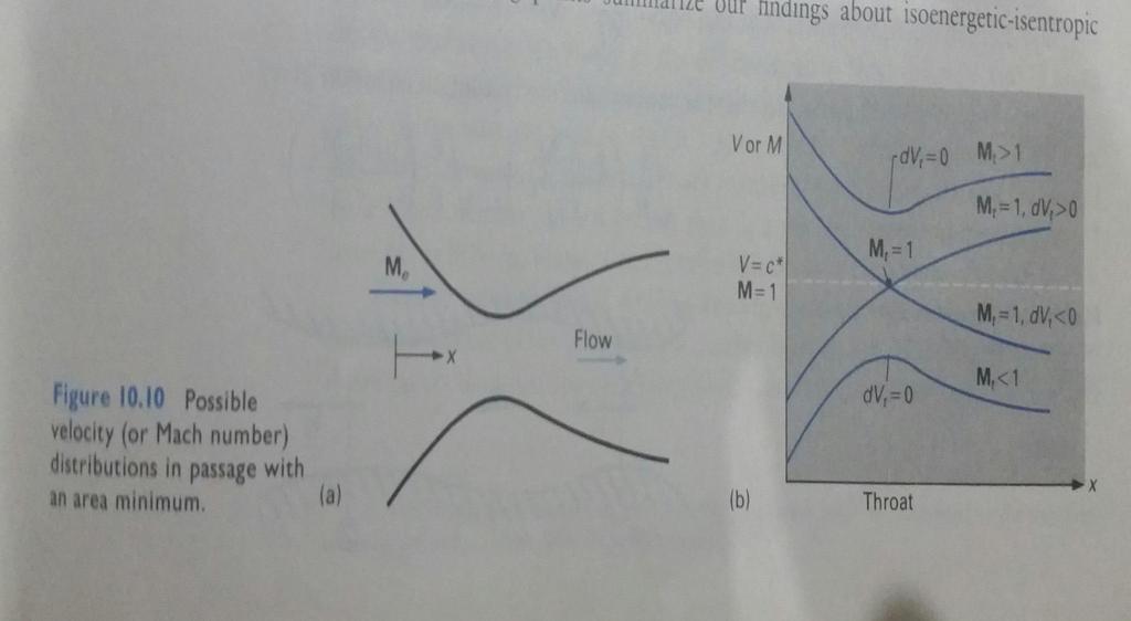
2 Summary of Results(Cont..) In isoenergetic-isentropic flow, an increase in velocity always corresponds to a Mach number increase and vice versa. Therefore, a converging passage always drive the Mach number towards the unity and diverging passage always drive the Mach number away from the unity. Suppose the Mach number is unity at some point in the flow. Since infinite acceleration (dv ) is not possible (Note: dv = ( 1 ) da ) unless there is V Ma 2 1 A shock wave, which is specifically excluded in assumptions, the bracketed equation then implies that da = 0 when Ma = 1. Finally suppose that the compressible fluid is flowing in a passage that actually has an area minimum (called Throat). Is it always possible to conclude that the Mach number is unity at the throat? If da is zero, then two options are possible: Ma = 1 or dv = 0, simply knowing da = 0 does not allow us to determine which condition occurs.
3
4 Conclusion The response of the flow to specific type of area change is exactly opposite for subsonic and supersonic flow (as described in the last lecture in tabulated form). Sonic flow (M = 1) can occur only at minimum area. Minimum areas occur at the inlet of simply diverging passage, the outlet of simply converging passage, and the throat of a converging and diverging passage. It is possible, but not necessary, that the Mach number at the throat of a converging-diverging passage be equal to 1. if the Mach number at the throat is not 1, the velocity must pass through a maximum or minimum. If the throat Mach number is 1, the fluid may either accelerate or de-accelerate down stream from the throat.
5 Steady Isentropic flow of an ideal gas (do by yourself) For flow of a compressible fluid in a small stream tube, we can make the following assumptions: 1. The flow is steady 2. There are no body forces(gravity, electromagnetic and others) 3. There are no shear stresses 4. There is no heat transfer 5. The stream tube does not pass through the a shock waves.* The last three assumptions taken together imply that the flow is adiabatic and reversible, therefore the entropy of the fluid is constant Ŝ = constant, (Ŝ1 = Ŝ2) For steady flow the energy equation is q w shaft w shear = h 2 + V h 1 + V According to our assumptions, q and w shear are zero. But the shaft is not necessarily zero, energy equation becomes w shaft = h 2 + V h 1 + V When we use the definition of stagnation enthalpy, w shaft = h o2 If the fluid is an ideal gas, w shaft = C p ( T o2 h o1 T o1 ).(1) *Assuming that there are no shocks If the flow is subsonic every where along the stream tube is not necessary, because the shocks are possible only if the inlet flow is supersonic.
6 Doing work on the fluid increases its stagnation temperature, even if there is no heat transfer. Now consider the changes of stagnation pressure in isentropic flow. By definition of stagnation state Ŝ = constant, (Ŝ 1 = Ŝ 2 ) Using the equation 1, we get Thus p o2 = ( T Cp o2 ) R p o1 T o1 = ( T o2 p o2 = (1 w shaft ) γ 1 p o1 C p T o1 A situation of considerable interest in compressible flow is the case with no shaft work. The following statement applies to this case: In the isentropic flow with no shaft work, all the stagnation properties are constant. T o1 ) γ γ γ 1 Stagnation properties are constant in isentropic flow only if there is no shaft work. This special case (w shaft = 0) is so important in compressible flow that some engineers and authors use the phrase isentropic flow to mean isentropic flow with no work. Here use the phrase isoenergetic-isentropic flow to refer to isentropic flow with no work. Equations relating property and velocity changes in isoenergetic-isentropic flow of an ideal gas can easily be developed from stagnation property definitions and constancy of stagnation properties. take, e.g. the calculation of change in temperature between two points in an isoenergetic-isentropic flow. Because To is constant, we can write T o1 = T 1 + V 1 2 = T 2C 2 + V 2 1 p 2C p = T o2
7 Using Mach number instead of velocity is sometimes convenient, above equation can be written in the following form T 2 = T 2 o2 1 + (γ 1) 2 M a1 T 2 1 T o1 1 + (γ 1) 2 M a2 A third approach involves the use of the table relating stagnation property ratioand Mach number. We calculate the temperature ratios by T 2 T T = M T 1 T 2 M o T 1 o Where T T o M is a numerical value read from the tabulated data at Mach Number M. In a fourth method, we make the calculations in two steps: T o2 = T o1 = T 1 T To M 1 and T 2 = T o2 T T o M 2
8 Any of the above equation could be used to relate the temperature and velocities ( or Mach number) at point 1 and 2. which equation is most convenient depends on the exact information available. Similarly pressure and velocity ( of Mach number) in iso-energetic and isentropic flow can be related by any of the following equations: p V 1 2 2T 1 C p γ γ 1 = p V 2 2 2T 2 C p γ γ 1 p 2 = 1 + p (γ 1) 2 M a1 2 γ γ 1 2 (γ 1) 2 M a2 γ γ 1 p 2 p 1 = p p M p 2 M o p 1 o p 2 = p o2 p p o M 2 where p o2 = p o1 = p 1 p p o M 1
 ρ 1 V 1 A 1 = ρ 2 V 2 A 2 For an ideal gas ρ = p RT and V = M ac = M a γrt Substituting the above equation into continuity equation gives γ R ρ 1 A 1 M a1 T 1 = γ R ρ 2 A 2 M a2 T")
9 Area-Mach Number Relation To obtain an equation relating area and Mach number, use continuity equation for a control volume with inflow at plane 1 and outflow at plane 2. (following figure) ρ 1 V 1 A 1 = ρ 2 V 2 A 2 For an ideal gas ρ = p RT and V = M ac = M a γrt Substituting the above equation into continuity equation gives γ R ρ 1 A 1 M a1 T 1 = γ R ρ 2 A 2 M a2 T 2 Simplifying the above equation gives the following A 2 A 1 = M a1 M a2 p 2 p 1 1 T2 T For isoenergetic-isentropic flow we can replace the temperature and pressure ratio A 2 = M a1 1 + γ 1 /2 M a2 A 1 M 2 a2 1 + γ 1 /2 M a1 If any of three quantities A 1, M a1, A 2, M a2 are specified, the fourth can be calculated. Usually A 1 and M a1 are known and M a2 or A 2 is to be found. If M a2 is given and A 2 is to be calculate then the calculations are simple, however, if A 2 is given and M a2 must be calculated, that is not so easy. 2 (γ+1) 2(γ 1)
 Plot of Area ratio function versus Mach number is given under and can be used to infer interesting")
10 Set M a1 = 1, A 1 = A* and drop the subscript 2 to get the following A A = 1 2 M a γ γ 1 2 M a 2 γ+1 2(γ 1) (you may find tabulated values of A/A* in the various Fluid Mechanics Texts) Plot of Area ratio function versus Mach number is given under and can be used to infer interesting information.
11 Conclusions A/A* is always greater than unity except at Mach number unity where the A/A* is 1. If the Mach number is given, there is single corresponding area ratio, so the problem of calculating the area required to obtain a given Mach number seems easy 1. If A/A* is known, there are two corresponding Mach numbers. Choice of proper Mach number for known area ratio requires more information than just the area ratio itself. Generally we must know the pressure ratio or other information besides area ratio to conclude the Mach number 2. Warning!! In a passage with the throat, the throat area (A t ) does not necessarily equal the critical area unless other evidence indicates it. 1 (if the initial Mach number is M a1 is less than 1 and desired final Mach number M a2 is greater than 1, a minimum area is exactly equal to A* must occur between the planes 1 and 2, otherwise flow cannot pass through M a =1) 2 (we can sometimes logically eliminate one of the possibilities. If we know that the flow is subsonic at a plane 1 and minimum area is exactly equal to A* does not occur between the planes 1 and 2, the flow at 2 cannot be supersonic.

12 Mass Flow Relations and Chocking Mathematics ( on white board)
13 Conclusion Suppose that p o and T o are fixed (isoenergetic-isentropic flow). A specified mass flow rate can be forced through a limiting area. No smaller area can pass that flow. Suppose that p o and T o are fixed (isoenergetic-isentropic flow). Any particular fixed geometry duct, with fixed minimum area, can pass only a certain maximum flow. Passage of this maximum mass flow occurs when the Mach number at the minimum area is 1. once the Mach number at the minimum area becomes 1, it is not possible to increase the mass flow rate. It is possible to increase the limiting mass flow in a fixed geometry duct or to force a specified mass flow through a smaller area by increasing p o T o. Doing work on a gas (compression) increases both p o and T o ; however, the ratio p o T o is usually increased by compression. Chocking The chocking phenomenon occurs in compressible duct flow when the local Mach number reaches 1 at the minimum area in the duct. When this occurs, the mass flow rate through the duct cannot be increased unless the ratio of stagnation pressure to square root of stagnation temperature is increased.
 is obviously subsonic (M= 0), so the flow in the entire nozzle is subsonic, with the possible exception of the nozzle exit.")
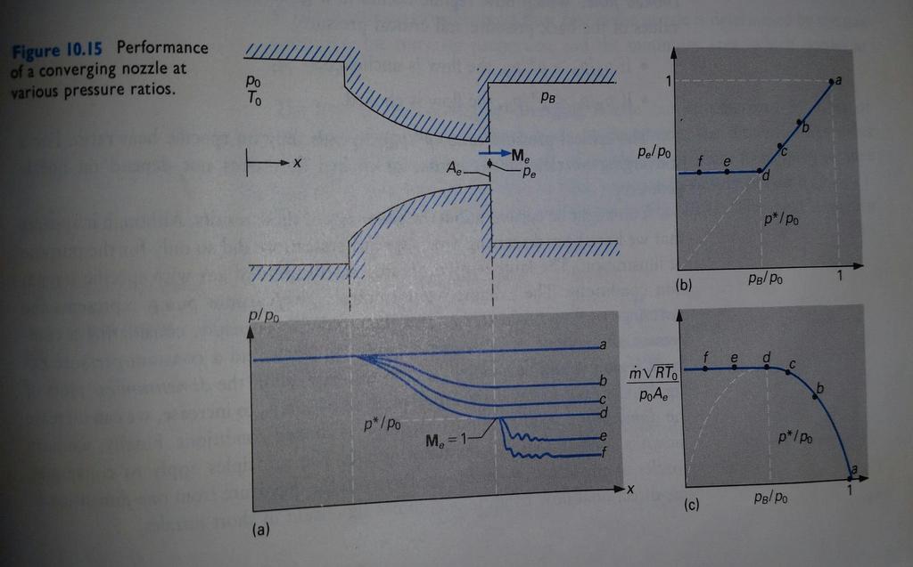
14 Flow through a converging Nozzle The nozzle is only convergent, so the flow cannot pass through M = 1. The flow at the nozzle inlet (in the large reservoir) is obviously subsonic (M= 0), so the flow in the entire nozzle is subsonic, with the possible exception of the nozzle exit. The flow cannot be supersonic in the nozzle, so there can be no shocks and the flow is isoenergetic-isentropic everywhere in the nozzle.the stagnation properties are constant and equal to the gas properties in the reservoir. The maximum possible Mach number in the nozzle is 1.0.this value can occur only at the nozzle exit (minimum area). There is a maximum possible mass flow rate that can occur only when the Mach number is 1 at the nozzle exit.
15 Discussion
16 Discussion (cont..) Curve labeled as a corresponds to a closed valve. There is no flow and pressure equals the reservoir pressure everywhere. Case b corresponds to slight opening of control valve. The back pressure is less than the supply pressure and there is flow. Minimum pressure and maximum Mach number are at the nozzle exit. We can calculate the mass flow rate by mass flow equation. Case c is similar to case b except larger control valve opening permits lower back pressure with correspondingly higher mass flow and exit Mach number and lower exit pressure. Note that Mach number is still less than 1. Case d, the control valve is sufficiently open to bring the exit Mach number to a value of 1. The exit pressure is now become critical pressure and also equals the back pressure. Mass flow rate can be calculated from the suitable equation. Case e corresponds to opening the control valve farther than in the case d. After trying this we find that no changes occur in the nozzle. In the case d, we reached the limit of nozzle s capability. The exit Mach number cannot exceed 1, the exit pressure cannot drop below the critical pressure, which can be determined from critical property formulas. The only difference between case d and case e is the back pressure and exit pressure are no longer equal. The flow must adjust to lower back pressure after leaving the nozzle. The down stream flow is multidimensional, so the pressure curve shown as a wavy line downstream from the nozzle exit. There are two regimes in simple converging nozzle If p B /p o > p * /p o, the flow is unchocked If p B /p o =< p * /p o, the flow is chocked
17 Flow through Converging-diverging Nozzle The nozzle is convergent-divergent, so the flow can pass through M a =1, the flow also can be subsonic everywhere. If M a =1 anywhere, it must be at the throat. There may be supersonic flow in the divergent portion of the nozzle, so there may be shocks in the flow. If there are shocks, the flow is not completely isentropic, although it is isoenergetic If there are no shocks, the flow is isentropic. if there are shocks, the flow from the reservoir up to the first shock is isentropic. Flow downstream from a shock also is isentropic but with different values of entropy, stagnation pressure, and critical area. The maximum possible Mach number that can occur anywhere in the passage corresponds to acceleration of the fluid in an isentropic process from the reservoir to the nozzle exit. The maximum possible Mach number can occur only at the exit and is determined by the ratio of exit area to throat area. The maximum possible mass flow rate in the nozzle is determined by the gas constant, the reservoir properties, and the minimum area, which occurs at the throat.

18 Flow through a Converging-Diverging Nozzle
19 Discussion Case a corresponds to complete closure of control valve. Curves and points labeled b represents a slightly open control valve. The gas accelerates in the convergent portion of the nozzle, and the pressure drops. The throat Mach number is less than 1. The pressure and Mach number distributions are roughly symmetrical about the throat. Exit and back pressure are equal. Curve c represents a slightly larger control valve opening. The pressure and Mach number situation is qualitatively similar to case b but the mass flow is larger. The maximum Mach number occurs at the throat. In case d the control valve has been opened just enough to bring the throat Mach number exactly to 1. The flow is still subsonic everywhere except exactly at the throat. The mass flow has reached a maximum and flow has just become chocked. The pressure rises downstream form the throat, so the back pressure at which convergingdiverging nozzle chokes is greater than p * /p o. The Pressure ratio at which this occur is called first critical pressure ratio. What happens when the valve is opened beyond the case d? Because the throat is chocked, the conditions upstream of throat cannot be affected. There is a response in flow downstream from the throat, because at case d the down stream flow is subsonic.
20 Discussion (Cont.) When the valve is opened and back pressure is lowered, the fluid begins to accelerate as it enters the divergent portion of the nozzle, i.e., the flow become supersonic. If the control valve is opened only slightly past the case d point, the downstream resistance is too large for complete acceleration in the divergent portion of the nozzle, so a shock occurs in the divergent portion. Curves and points labeled as e represents the flow for a slightly more open control valve. The flow accelerate in the converging portion of the nozzle, reaches sonic speed at the throat, and accelerates to supersonic speed downstream from the throat. The supersonic acceleration terminates in the shock wave. Downstream from the shock, the flow experiences subsonic de-accleration and exits the passage with Ma<1. The exit and back pressure are equal. The exact position of of the shock depends on the back pressure, and for a given back pressure, is fixed. The mass flow rate for case e, as well as for all lower values of back pressure, is the same as for the case of d. Opening the control valve and lowering the back pressure causes the shock to move downstream (case f). Note, that once the shock passes a plane, the flow up to that plane is no longer affected by lowering the back pressure. As the valve is opened further, the shock is eventually drawn to nozzle exit. The flow accelerates isentropically all the way from reservoir to the exit shock. Exactly at the exit, the pressure jumps to the back pressure as the fluid exits through the shocks. The situation is shown as case g. Note that the exit pressure is doubled at the case of g.
21 Discussion (Cont.) Lowering the back pressure further causes the shock to move out of the nozzle and become multidimensional (case h). The flow accelerates isentropically from the reservoir to the exit. The gas exits the nozzle supersonically with Ma corresponding to the nozzle s exit-tothroat area ratio. The exit pressure is determined only by the stagnation pressure (p O1 ) and the exit Mach number and is not equal to the back pressure. The gas adjusts to the back pressure externally. If we continue to lower the back pressure, it eventually reaches equality with the exit pressure (case i). At this condition, there is no pressure adjustment in the exiting gas. Lowering the pressure further (case j) requires external expansion pressure adjustments but does not the affect the nozzle flow.
22 Summary of Discussion We can summarize this information about converging diverging nozzle flow as follow. There are four regimes of flow in a converging diverging nozzle. Venturi regime (cases a d). The flow is subsonic and isentropic everywhere. The flow accelerates in the convergent portion and decelerates in the divergent portion. Maximum Mach number and minimum pressure occur at the throat. Shock regime (cases d g). The flow is subsonic in the convergent portion, sonic at the throat, and partly supersonic in the divergent portion. The acceleration terminates in a shock that stands in the divergent portion at a location determined by the exact value of the back pressure. The flow experiences subsonic deceleration from the shock to the exit. The flow is choked. Over expanded regime (cases g i). The flow accelerates throughout the nozzle. The throat flow is sonic, and the exit flow is supersonic. The pressure of the gas increases to the back pressure downstream from the nozzle exit. Under expanded regime (cases i j). This case is similar to the over expanded regime, except that the external pressure adjustments are expensive rather than compressive.
Isentropic Duct Flows
 An Internet Book on Fluid Dynamics Isentropic Duct Flows In this section we examine the behavior of isentropic flows, continuing the development of the relations in section (Bob). First it is important
Compressible Duct Flow with Friction
 Compressible Duct Flow with Friction We treat only the effect of friction, neglecting area change and heat transfer. The basic assumptions are 1. Steady one-dimensional adiabatic flow 2. Perfect gas with
SPC 407 Sheet 2 - Solution Compressible Flow - Governing Equations
 SPC 407 Sheet 2 - Solution Compressible Flow - Governing Equations 1. Is it possible to accelerate a gas to a supersonic velocity in a converging nozzle? Explain. No, it is not possible. The only way to
In which of the following scenarios is applying the following form of Bernoulli s equation: steady, inviscid, uniform stream of water. Ma = 0.
 bernoulli_11 In which of the following scenarios is applying the following form of Bernoulli s equation: p V z constant! g + g + = from point 1 to point valid? a. 1 stagnant column of water steady, inviscid,
P 1 P * 1 T P * 1 T 1 T * 1. s 1 P 1
 ME 131B Fluid Mechanics Solutions to Week Three Problem Session: Isentropic Flow II (1/26/98) 1. From an energy view point, (a) a nozzle is a device that converts static enthalpy into kinetic energy. (b)
1. For an ideal gas, internal energy is considered to be a function of only. YOUR ANSWER: Temperature
 CHAPTER 11 1. For an ideal gas, internal energy is considered to be a function of only. YOUR ANSWER: Temperature 2.In Equation 11.7 the subscript p on the partial derivative refers to differentiation at
IX. COMPRESSIBLE FLOW. ρ = P
 IX. COMPRESSIBLE FLOW Compressible flow is the study of fluids flowing at speeds comparable to the local speed of sound. This occurs when fluid speeds are about 30% or more of the local acoustic velocity.
Introduction to Chemical Engineering Thermodynamics. Chapter 7. KFUPM Housam Binous CHE 303
 Introduction to Chemical Engineering Thermodynamics Chapter 7 1 Thermodynamics of flow is based on mass, energy and entropy balances Fluid mechanics encompasses the above balances and conservation of momentum
Applied Gas Dynamics Flow With Friction and Heat Transfer
 Applied Gas Dynamics Flow With Friction and Heat Transfer Ethirajan Rathakrishnan Applied Gas Dynamics, John Wiley & Sons (Asia) Pte Ltd c 2010 Ethirajan Rathakrishnan 1 / 121 Introduction So far, we have
Richard Nakka's Experimental Rocketry Web Site
 Página 1 de 7 Richard Nakka's Experimental Rocketry Web Site Solid Rocket Motor Theory -- Nozzle Theory Nozzle Theory The rocket nozzle can surely be described as the epitome of elegant simplicity. The
SPC 407 Sheet 5 - Solution Compressible Flow Rayleigh Flow
 SPC 407 Sheet 5 - Solution Compressible Flow Rayleigh Flow 1. Consider subsonic Rayleigh flow of air with a Mach number of 0.92. Heat is now transferred to the fluid and the Mach number increases to 0.95.
Chapter 17. For the most part, we have limited our consideration so COMPRESSIBLE FLOW. Objectives
 Chapter 17 COMPRESSIBLE FLOW For the most part, we have limited our consideration so far to flows for which density variations and thus compressibility effects are negligible. In this chapter we lift this
Introduction to Fluid Mechanics. Chapter 13 Compressible Flow. Fox, Pritchard, & McDonald
 Introduction to Fluid Mechanics Chapter 13 Compressible Flow Main Topics Basic Equations for One-Dimensional Compressible Flow Isentropic Flow of an Ideal Gas Area Variation Flow in a Constant Area Duct
Please welcome for any correction or misprint in the entire manuscript and your valuable suggestions kindly mail us
 Problems of Practices Of Fluid Mechanics Compressible Fluid Flow Prepared By Brij Bhooshan Asst. Professor B. S. A. College of Engg. And Technology Mathura, Uttar Pradesh, (India) Supported By: Purvi Bhooshan
2013/5/22. ( + ) ( ) = = momentum outflow rate. ( x) FPressure. 9.3 Nozzles. δ q= heat added into the fluid per unit mass
 ( ) = = momentum outflow rate. ( x) FPressure. 9.3 Nozzles. δ q= heat added into the fluid per unit mass") 9.3 Nozzles (b) omentum conservation : (i) Governing Equations Consider: nonadiabatic ternal (body) force ists variable flow area continuously varying flows δq f ternal force per unit volume +d δffdx dx
9.3 Nozzles (b) omentum conservation : (i) Governing Equations Consider: nonadiabatic ternal (body) force ists variable flow area continuously varying flows δq f ternal force per unit volume +d δffdx dx
Review of Fundamentals - Fluid Mechanics
 Review of Fundamentals - Fluid Mechanics Introduction Properties of Compressible Fluid Flow Basics of One-Dimensional Gas Dynamics Nozzle Operating Characteristics Characteristics of Shock Wave A gas turbine
Jet Aircraft Propulsion Prof. Bhaskar Roy Prof. A.M. Pradeep Department of Aerospace Engineering
 Jet Aircraft Propulsion Prof. Bhaskar Roy Prof. A.M. Pradeep Department of Aerospace Engineering Indian Institute of Technology, IIT Bombay Module No. # 01 Lecture No. # 08 Cycle Components and Component
 Tutorial Materials for ME 131B Fluid Mechanics (Compressible Flow & Turbomachinery) Calvin Lui Department of Mechanical Engineering Stanford University Stanford, CA 94305 March 1998 Acknowledgments This
Notes #4a MAE 533, Fluid Mechanics
 Notes #4a MAE 533, Fluid Mechanics S. H. Lam lam@princeton.edu http://www.princeton.edu/ lam October 23, 1998 1 The One-dimensional Continuity Equation The one-dimensional steady flow continuity equation
Fundamentals of Gas Dynamics (NOC16 - ME05) Assignment - 8 : Solutions
 Assignment - 8 : Solutions") Fundamentals of Gas Dynamics (NOC16 - ME05) Assignment - 8 : Solutions Manjul Sharma & Aswathy Nair K. Department of Aerospace Engineering IIT Madras April 5, 016 (Note : The solutions discussed below
Fundamentals of Gas Dynamics (NOC16 - ME05) Assignment - 8 : Solutions Manjul Sharma & Aswathy Nair K. Department of Aerospace Engineering IIT Madras April 5, 016 (Note : The solutions discussed below
HIGH SPEED GAS DYNAMICS HINCHEY
 HIGH SPEED GAS DYNAMICS HINCHEY MACH WAVES Mach Number is the speed of something divided by the local speed of sound. When an infinitesimal disturbance moves at a steady speed, at each instant in time
One-Dimensional Isentropic Flow
 Cairo University Second Year Faculty of Engineering Gas Dynamics AER 201B Aerospace Department Sheet (1) 2011-2012 One-Dimensional Isentropic Flow 1. Assuming the flow of a perfect gas in an adiabatic,
Fundamentals of Gas Dynamics (NOC16 - ME05) Assignment - 10 : Solutions
 Assignment - 10 : Solutions") Fundamentals of Gas Dynamics (NOC16 - ME05) Assignment - 10 : Solutions Manjul Sharma & Aswathy Nair K. Department of Aerospace Engineering IIT Madras April 18, 016 (Note : The solutions discussed below
Fundamentals of Gas Dynamics (NOC16 - ME05) Assignment - 10 : Solutions Manjul Sharma & Aswathy Nair K. Department of Aerospace Engineering IIT Madras April 18, 016 (Note : The solutions discussed below
Steady waves in compressible flow
 Chapter Steady waves in compressible flow. Oblique shock waves Figure. shows an oblique shock wave produced when a supersonic flow is deflected by an angle. Figure.: Flow geometry near a plane oblique
Fluid Mechanics - Course 123 COMPRESSIBLE FLOW
 Fluid Mechanics - Course 123 COMPRESSIBLE FLOW Flow of compressible fluids in a p~pe involves not only change of pressure in the downstream direction but also a change of both density of the fluid and
1. (20 pts total 2pts each) - Circle the most correct answer for the following questions.
 - Circle the most correct answer for the following questions.") ME 50 Gas Dynamics Spring 009 Final Exam NME:. (0 pts total pts each) - Circle the most correct answer for the following questions. i. normal shock propagated into still air travels with a speed (a) equal
ME 50 Gas Dynamics Spring 009 Final Exam NME:. (0 pts total pts each) - Circle the most correct answer for the following questions. i. normal shock propagated into still air travels with a speed (a) equal
Shock and Expansion Waves
 Chapter For the solution of the Euler equations to represent adequately a given large-reynolds-number flow, we need to consider in general the existence of discontinuity surfaces, across which the fluid
SPC 407 Sheet 6 - Solution Compressible Flow Fanno Flow
 SPC 407 Sheet 6 - Solution Comressible Flow Fanno Flow 1. What is the effect of friction on flow velocity in subsonic and suersonic Fanno flow? Friction increases the flow velocity in subsonic Fanno flow,
6.1 According to Handbook of Chemistry and Physics the composition of air is
 6. Compressible flow 6.1 According to Handbook of Chemistry and Physics the composition of air is From this, compute the gas constant R for air. 6. The figure shows a, Pitot-static tube used for velocity
Rocket Thermodynamics
 Rocket Thermodynamics PROFESSOR CHRIS CHATWIN LECTURE FOR SATELLITE AND SPACE SYSTEMS MSC UNIVERSITY OF SUSSEX SCHOOL OF ENGINEERING & INFORMATICS 25 TH APRIL 2017 Thermodynamics of Chemical Rockets ΣForce
SUPERSONIC WIND TUNNEL Project One. Charles R. O Neill School of Mechanical and Aerospace Engineering Oklahoma State University Stillwater, OK 74078
 41 SUPERSONIC WIND UNNEL Project One Charles R. O Neill School of Mechanical and Aerospace Engineering Oklahoma State University Stillwater, OK 74078 Project One in MAE 3293 Compressible Flow September
Notes #6 MAE 533, Fluid Mechanics
 Notes #6 MAE 533, Fluid Mechanics S. H. Lam lam@princeton.edu http://www.princeton.edu/ lam October 1, 1998 1 Different Ways of Representing T The speed of sound, a, is formally defined as ( p/ ρ) s. It
Fanno Flow. Gas Dynamics
 Fanno Flow Simple frictional flow ( Fanno Flow Adiabatic frictional flow in a constant-area duct * he Flow of a compressible fluid in a duct is Always accompanied by :- ariation in the cross sectional
1 One-dimensional analysis
 One-dimensional analysis. Introduction The simplest models for gas liquid flow systems are ones for which the velocity is uniform over a cross-section and unidirectional. This includes flows in a long
Figure 1. Mach cone that arises upon supersonic flow around an object
 UNIT I BASIC CONCEPTS AND ISENTROPIC FLOWS Introduction The purpose of this applet is to simulate the operation of a converging-diverging nozzle, perhaps the most important and basic piece of engineering
Rocket Propulsion Prof. K. Ramamurthi Department of Mechanical Engineering Indian Institute of Technology, Madras
 Rocket Propulsion Prof. K. Ramamurthi Department of Mechanical Engineering Indian Institute of Technology, Madras Lecture 11 Area Ratio of Nozzles: Under Expansion and Over Expansion (Refer Slide Time:
Objectives. Conservation of mass principle: Mass Equation The Bernoulli equation Conservation of energy principle: Energy equation
 Objectives Conservation of mass principle: Mass Equation The Bernoulli equation Conservation of energy principle: Energy equation Conservation of Mass Conservation of Mass Mass, like energy, is a conserved
EVALUATION OF THE BEHAVIOUR OF STEAM EXPANDED IN A SET OF NOZZLES, IN A GIVEN TEMPERATURE
 Equatorial Journal of Engineering (2018) 9-13 Journal Homepage: www.erjournals.com ISSN: 0184-7937 EVALUATION OF THE BEHAVIOUR OF STEAM EXPANDED IN A SET OF NOZZLES, IN A GIVEN TEMPERATURE Kingsley Ejikeme
Final 1. (25) 2. (10) 3. (10) 4. (10) 5. (10) 6. (10) TOTAL = HW = % MIDTERM = % FINAL = % COURSE GRADE =
 2. (10) 3. (10) 4. (10) 5. (10) 6. (10) TOTAL = HW = % MIDTERM = % FINAL = % COURSE GRADE =") MAE101B: Advanced Fluid Mechanics Winter Quarter 2017 http://web.eng.ucsd.edu/~sgls/mae101b_2017/ Name: Final This is a three hour open-book exam. Please put your name on the top sheet of the exam. Answer
MAE101B: Advanced Fluid Mechanics Winter Quarter 2017 http://web.eng.ucsd.edu/~sgls/mae101b_2017/ Name: Final This is a three hour open-book exam. Please put your name on the top sheet of the exam. Answer
UOT Mechanical Department / Aeronautical Branch
 Chapter One/Introduction to Compressible Flow Chapter One/Introduction to Compressible Flow 1.1. Introduction In general flow can be subdivided into: i. Ideal and real flow. For ideal (inviscid) flow viscous
MCE380: Measurements and Instrumentation Lab
 MCE380: Measurements and Instrumentation Lab Chapter 8: Flow Measurements Topics: Basic Flow Equations Flow Obstruction Meters Positive Displacement Flowmeters Other Methods Holman, Ch. 7 Cleveland State
Civil aeroengines for subsonic cruise have convergent nozzles (page 83):
:") 120 Civil aeroengines for subsonic cruise have convergent nozzles (page 83): Choked convergent nozzle must be sonic at the exit A N. Consequently, the pressure (p 19 ) at the nozzle exit will be above
120 Civil aeroengines for subsonic cruise have convergent nozzles (page 83): Choked convergent nozzle must be sonic at the exit A N. Consequently, the pressure (p 19 ) at the nozzle exit will be above
DESIGN & COMPUTATIONAL FLUID DYNAMICS ANALYSES OF AN AXISYMMETRIC NOZZLE AT TRANSONIC FREE STREAM CONDITIONS
 DESIGN & COMPUTATIONAL FLUID DYNAMICS ANALYSES OF AN AXISYMMETRIC NOZZLE AT TRANSONIC FREE STREAM CONDITIONS S Wasim Akram 1, S. Rajesh 2 1 M.Tech Student, Department of Mechanical Engineering, Krishna
AOE 3114 Compressible Aerodynamics
 AOE 114 Compressible Aerodynamics Primary Learning Objectives The student will be able to: 1. Identify common situations in which compressibility becomes important in internal and external aerodynamics
vector H. If O is the point about which moments are desired, the angular moment about O is given:
 The angular momentum A control volume analysis can be applied to the angular momentum, by letting B equal to angularmomentum vector H. If O is the point about which moments are desired, the angular moment
Introduction to Aerospace Engineering
 Introduction to Aerospace Engineering Lecture slides Challenge the future 3-0-0 Introduction to Aerospace Engineering Aerodynamics 5 & 6 Prof. H. Bijl ir. N. Timmer Delft University of Technology 5. Compressibility
GAS DYNAMICS AND JET PROPULSION
 GAS DYNAMICS AND JE PROPULSION 1. What is the basic difference between compressible and incompressible fluid flow? Compressible Incompressible 1. Fluid velocities are appreciable 1. Fluid velocities are
CHAPTER 5 MASS AND ENERGY ANALYSIS OF CONTROL VOLUMES
 Thermodynamics: An Engineering Approach 8th Edition in SI Units Yunus A. Çengel, Michael A. Boles McGraw-Hill, 2015 CHAPTER 5 MASS AND ENERGY ANALYSIS OF CONTROL VOLUMES Lecture slides by Dr. Fawzi Elfghi
Lecture 55 Compressible Flows (Contd.)
") Introduction to Fluid Mechanics and Fluid Engineering Prof. Suman Chakraborty Department of Mechanical Engineering Indian Institute of Technology Kharagpur Lecture 55 Compressible Flows (Contd.) We will
Introduction to Fluid Mechanics and Fluid Engineering Prof. Suman Chakraborty Department of Mechanical Engineering Indian Institute of Technology Kharagpur Lecture 55 Compressible Flows (Contd.) We will
Gasdynamics 1-D compressible, inviscid, stationary, adiabatic flows
 Gasdynamics 1-D compressible, inviscid, stationary, adiabatic flows 1st law of thermodynamics ρ const Kontrollfläche 1 2 m u 2 u 1 z Q 12 +P 12 = ṁ } h 2 h {{} 1 Enthalpy Q 12 + 1 2 (u2 2 u2 1 }{{} ) +
Brown Hills College of Engineering & Technology
 UNIT 4 Flow Through Nozzles Velocity and heat drop, Mass discharge through a nozzle, Critical pressure ratio and its significance, Effect of friction, Nozzle efficiency, Supersaturated flow, Design pressure
Lecture with Numerical Examples of Ramjet, Pulsejet and Scramjet
 Lecture 41 1 Lecture with Numerical Examples of Ramjet, Pulsejet and Scramjet 2 Problem-1 Ramjet A ramjet is flying at Mach 1.818 at an altitude 16.750 km altitude (Pa = 9.122 kpa, Ta= - 56.5 0 C = 216.5
Mass flow determination in flashing openings
 Int. Jnl. of Multiphysics Volume 3 Number 4 009 40 Mass flow determination in flashing openings Geanette Polanco Universidad Simón Bolívar Arne Holdø Narvik University College George Munday Coventry University
THEORETICAL AND EXPERIMENTAL INVESTIGATIONS ON CHOKING PHENOMENA OF AXISYMMETRIC CONVERGENT NOZZLE FLOW
 8 TH INTERNATIONAL CONGRESS OF THE AERONAUTICAL SCIENCES THEORETICAL AND EXPERIMENTAL INVESTIGATIONS ON CHOKING PHENOMENA OF AXISYMMETRIC CONVERGENT NOZZLE FLOW Ryuta ISOZUMI*, Kazunori KUBO*, Daisuke
Lecture23. Flowmeter Design.
 Lecture23 Flowmeter Design. Contents of lecture Design of flowmeter Principles of flow measurement; i) Venturi and ii) Orifice meter and nozzle Relationship between flow rate and pressure drop Relation
Aerothermodynamics of High Speed Flows
 Aerothermodynamics of High Speed Flows Lecture 5: Nozzle design G. Dimitriadis 1 Introduction Before talking about nozzle design we need to address a very important issue: Shock reflection We have already
Introduction to Fluid Machines, and Compressible Flow Prof. S. K. Som Department of Mechanical Engineering Indian Institute of Technology, Kharagpur
 Introduction to Fluid Machines, and Compressible Flow Prof. S. K. Som Department of Mechanical Engineering Indian Institute of Technology, Kharagpur Lecture - 09 Introduction to Reaction Type of Hydraulic
The ramjet cycle. Chapter Ramjet flow field
 Chapter 3 The ramjet cycle 3. Ramjet flow field Before we begin to analyze the ramjet cycle we will consider an example that can help us understand how the flow through a ramjet comes about. The key to
High Speed Aerodynamics. Copyright 2009 Narayanan Komerath
 Welcome to High Speed Aerodynamics 1 Lift, drag and pitching moment? Linearized Potential Flow Transformations Compressible Boundary Layer WHAT IS HIGH SPEED AERODYNAMICS? Airfoil section? Thin airfoil
Introduction to Gas Dynamics All Lecture Slides
 Introduction to Gas Dynamics All Lecture Slides Teknillinen Korkeakoulu / Helsinki University of Technology Autumn 009 1 Compressible flow Zeroth law of thermodynamics 3 First law of thermodynamics 4 Equation
Mass of fluid leaving per unit time
 5 ENERGY EQUATION OF FLUID MOTION 5.1 Eulerian Approach & Control Volume In order to develop the equations that describe a flow, it is assumed that fluids are subject to certain fundamental laws of physics.
UNIT 1 COMPRESSIBLE FLOW FUNDAMENTALS
 UNIT 1 COMPRESSIBLE FLOW FUNDAMENTALS 1) State the difference between compressible fluid and incompressible fluid? 2) Define stagnation pressure? 3) Express the stagnation enthalpy in terms of static enthalpy
Isentropic Efficiency in Engineering Thermodynamics
 June 21, 2010 Isentropic Efficiency in Engineering Thermodynamics Introduction This article is a summary of selected parts of chapters 4, 5 and 6 in the textbook by Moran and Shapiro (2008. The intent
Jet Aircraft Propulsion Prof. Bhaskar Roy Prof A M Pradeep Department of Aerospace Engineering Indian Institute of Technology, Bombay
 Jet Aircraft Propulsion Prof. Bhaskar Roy Prof A M Pradeep Department of Aerospace Engineering Indian Institute of Technology, Bombay Module No. #01 Lecture No. # 07 Jet Engine Cycles For Aircraft propulsion
4 Compressible Fluid Dynamics
 4 Compressible Fluid Dynamics 4. Compressible flow definitions Compressible flow describes the behaviour of fluids that experience significant variations in density under the application of external pressures.
Introduction to Fluid Machines and Compressible Flow Prof. S.K Som Department of Mechanical Engineering Indian Institute of Technology, Kharagpur
 Introduction to Fluid Machines and Compressible Flow Prof. S.K Som Department of Mechanical Engineering Indian Institute of Technology, Kharagpur Lecture No. # 24 Axial Flow Compressor Part I Good morning
Lecture 5 Flusso Quasi-Mono-Dimensionale (forma
 Lecture 5 Dimensionale forma Text: Motori Aeronautici Mar. 6, 2015 Dimensionale forma Mauro Valorani Univeristà La Sapienza 5.50 Agenda Dimensionale forma 1 quasi-monodimensionale 2 5.51 quasi-monodimensionale
MODELING & SIMULATION OF ROCKET NOZZLE
 MODELING & SIMULATION OF ROCKET NOZZLE Nirmith Kumar Mishra, Dr S Srinivas Prasad, Mr Ayub Padania Department of Aerospace Engineering MLR Institute of Technology Hyderabad, T.S Abstract This project develops
the pitot static measurement equal to a constant C which is to take into account the effect of viscosity and so on.
 Mechanical Measurements and Metrology Prof. S. P. Venkateshan Department of Mechanical Engineering Indian Institute of Technology, Madras Module -2 Lecture - 27 Measurement of Fluid Velocity We have been
first law of ThermodyNamics
 first law of ThermodyNamics First law of thermodynamics - Principle of conservation of energy - Energy can be neither created nor destroyed Basic statement When any closed system is taken through a cycle,
AGENA ROCKET NOZZLE: PROPERTIES AND GEOMETRY. Charles R. O Neill. School of Mechanical and Aerospace Engineering. Oklahoma State University
 AGENA ROCKET NOZZLE: PROPERTIES AND GEOMETRY Charles R. O Neill School of Mechanical and Aerospace Engineering Oklahoma State University Stillwater, OK 74078 MAE 443 Project 1 Gas Power Oct 0, 000 Agena
Experimental Study of Steam Flow in a Convergent-Divergent Nozzle
 Experimental Study of Steam Flow in a Convergent-Divergent Nozzle 1 Marwa H. Athab, 2 Arkan Al-Taie, 3 Hussein W. Mashi 1 M.SC Student, 2 Professor, 3 Lecturer, Mechanical Engineering Department, UOT Abstract:
Compressible Gas Flow
 Compressible Gas Flow by Elizabeth Adolph Submitted to Dr. C. Grant Willson CHE53M Department of Chemical Engineering The University of Texas at Austin Fall 008 Compressible Gas Flow Abstract In this lab,
Flow Characteristic Through Convergent-Divergent Nozzle
 2018 IJSRST Volume 4 Issue 2 Print ISSN: 2395-6011 Online ISSN: 2395-602X Themed Section: Science and Technology Flow Characteristic Through Convergent-Divergent Nozzle S. Sathyapriya 1, R. Swathi 2, P.
5 ENERGY EQUATION OF FLUID MOTION
 5 ENERGY EQUATION OF FLUID MOTION 5.1 Introduction In order to develop the equations that describe a flow, it is assumed that fluids are subject to certain fundamental laws of physics. The pertinent laws
Signature: (Note that unsigned exams will be given a score of zero.)
") Neatly print your name: Signature: (Note that unsigned exams will be given a score of zero.) Circle your lecture section (-1 point if not circled, or circled incorrectly): Prof. Dabiri Prof. Wassgren Prof.
Neatly print your name: Signature: (Note that unsigned exams will be given a score of zero.) Circle your lecture section (-1 point if not circled, or circled incorrectly): Prof. Dabiri Prof. Wassgren Prof.
Modelling and Computational Fluid Dynamic Analysis on Jet Nozzle
 Modelling and Computational Fluid Dynamic Analysis on Jet Nozzle 1 Shaik Khaja Hussain, 2 B V Amarnath Reddy, 3 A V Hari Babu 1 Research Scholar, 2 Assistant Professor, 3 HOD Mechanical Engineering Department
SATHYABAMA UNIVERISTY. Unit III
 Unit III UNIT III STEAM NOZZLES AND TURBINES Flow of steam through nozzles, shapes of nozzles, effect of friction, critical pressure ratio,supersaturated flow.impulse and reaction principles, compounding,
CHAPTER 7 SEVERAL FORMS OF THE EQUATIONS OF MOTION
 CHAPTER 7 SEVERAL FORMS OF THE EQUATIONS OF MOTION 7.1 THE NAVIER-STOKES EQUATIONS Under the assumption of a Newtonian stress-rate-of-strain constitutive equation and a linear, thermally conductive medium,
Turbomachinery & Turbulence. Lecture 2: One dimensional thermodynamics.
 Turbomachinery & Turbulence. Lecture 2: One dimensional thermodynamics. F. Ravelet Laboratoire DynFluid, Arts et Metiers-ParisTech February 3, 2016 Control volume Global balance equations in open systems
Compressible Flow. Professor Ugur GUVEN Aerospace Engineer Spacecraft Propulsion Specialist
 Compressible Flow Professor Ugur GUVEN Aerospace Engineer Spacecraft Propulsion Specialist What is Compressible Flow? Compressible Flow is a type of flow in which the density can not be treated as constant.
CHOKING PRESSURE RATIO GUIDELINES FOR SMALL CRITICAL FLOW VENTURIS AND THE EFFECTS OF DIFFUSER GEOMETRY
 CHOKING PRESSURE RATIO GUIDELINES FOR SMALL CRITICAL FLOW VENTURIS AND THE EFFECTS OF DIFFUSER GEOMETRY Michael S. Carter, Flow Systems Inc., mcarter@flowsystemsinc.com Bradford W. Sims, Flow Systems Inc.,
Angular momentum equation
 Angular momentum equation For angular momentum equation, B =H O the angular momentum vector about point O which moments are desired. Where β is The Reynolds transport equation can be written as follows:
Computational Analysis of Bell Nozzles
 Proceedings of the 4 th International Conference of Fluid Flow, Heat and Mass Transfer (FFHMT'17) Toronto, Canada August 21 23, 2017 Paper No. 110 DOI: 10.11159/ffhmt17.110 Computational Analysis of Bell
AEROSPACE ENGINEERING DEPARTMENT. Second Year - Second Term ( ) Fluid Mechanics & Gas Dynamics
 Fluid Mechanics & Gas Dynamics") AEROSPACE ENGINEERING DEPARTMENT Second Year - Second Term (2008-2009) Fluid Mechanics & Gas Dynamics Similitude,Dimensional Analysis &Modeling (1) [7.2R*] Some common variables in fluid mechanics include:
AEROSPACE ENGINEERING DEPARTMENT Second Year - Second Term (2008-2009) Fluid Mechanics & Gas Dynamics Similitude,Dimensional Analysis &Modeling (1) [7.2R*] Some common variables in fluid mechanics include:
Introduction. In general, gases are highly compressible and liquids have a very low compressibility. COMPRESSIBLE FLOW
 COMRESSIBLE FLOW COMRESSIBLE FLOW Introduction he compressibility of a fluid is, basically, a measure of the change in density that will be produced in the fluid by a specific change in pressure and temperature.
for what specific application did Henri Pitot develop the Pitot tube? what was the name of NACA s (now NASA) first research laboratory?
 first research laboratory?") 1. 5% short answers for what specific application did Henri Pitot develop the Pitot tube? what was the name of NACA s (now NASA) first research laboratory? in what country (per Anderson) was the first
1. 5% short answers for what specific application did Henri Pitot develop the Pitot tube? what was the name of NACA s (now NASA) first research laboratory? in what country (per Anderson) was the first
Week 8. Steady Flow Engineering Devices. GENESYS Laboratory
 Week 8. Steady Flow Engineering Devices Objectives 1. Solve energy balance problems for common steady-flow devices such as nozzles, compressors, turbines, throttling valves, mixers, heaters, and heat exchangers
Design and Optimization of De Lavel Nozzle to Prevent Shock Induced Flow Separation
 Advances in Aerospace Science and Applications. ISSN 2277-3223 Volume 3, Number 2 (2013), pp. 119-124 Research India Publications http://www.ripublication.com/aasa.htm Design and Optimization of De Lavel
Influence of Molecular Complexity on Nozzle Design for an Organic Vapor Wind Tunnel
 ORC 2011 First International Seminar on ORC Power Systems, Delft, NL, 22-23 September 2011 Influence of Molecular Complexity on Nozzle Design for an Organic Vapor Wind Tunnel A. Guardone, Aerospace Eng.
6.1 Propellor e ciency
 Chapter 6 The Turboprop cycle 6. Propellor e ciency The turboprop cycle can be regarded as a very high bypass limit of a turbofan. Recall that the propulsive e ciency of a thruster with P e = P 0 and f
Notes 4: Differential Form of the Conservation Equations
 Low Speed Aerodynamics Notes 4: Differential Form of the Conservation Equations Deriving Conservation Equations From the Laws of Physics Physical Laws Fluids, being matter, must obey the laws of Physics.
Radial Compressors. Damian Vogt Course MJ2429. Nomenclature
 Turbomachinery Lecture Notes 1 007-10-04 Radial Compressors Damian Vogt Course MJ49 Nomenclature Subscripts Symbol Denotation Unit c Absolute velocity m/s h Enthalpy J/kg m& Mass flow rate kg/s r Radius
Thermodynamics ENGR360-MEP112 LECTURE 7
 Thermodynamics ENGR360-MEP11 LECTURE 7 Thermodynamics ENGR360/MEP11 Objectives: 1. Conservation of mass principle.. Conservation of energy principle applied to control volumes (first law of thermodynamics).
Introduction to Turbomachinery
 1. Coordinate System Introduction to Turbomachinery Since there are stationary and rotating blades in turbomachines, they tend to form a cylindrical form, represented in three directions; 1. Axial 2. Radial
Various lecture notes for
 Various lecture notes for 18311. R. R. Rosales (MIT, Math. Dept., 2-337) April 12, 2013 Abstract Notes, both complete and/or incomplete, for MIT s 18.311 (Principles of Applied Mathematics). These notes
The deposition efficiency and spatial thickness distribution of films created by Directed
 Chapter 8 Vapor Transport Model Development The deposition efficiency and spatial thickness distribution of films created by Directed Vapor Deposition synthesis have been shown to be sensitive functions
AerE 344: Undergraduate Aerodynamics and Propulsion Laboratory. Lab Instructions. Pressure Measurements in a de Laval Nozzle
 AerE 344: Undergraduate Aerodynamics and ropulsion Laboratory Lab Instructions Lab #0: ressure easurements in a de Laval Nozzle Instructor: Dr. Hui Hu Department of Aerospace Engineering Iowa State University
2 Navier-Stokes Equations
 1 Integral analysis 1. Water enters a pipe bend horizontally with a uniform velocity, u 1 = 5 m/s. The pipe is bended at 90 so that the water leaves it vertically downwards. The input diameter d 1 = 0.1
Aerodynamics. Basic Aerodynamics. Continuity equation (mass conserved) Some thermodynamics. Energy equation (energy conserved)
 Some thermodynamics. Energy equation (energy conserved)") Flow with no friction (inviscid) Aerodynamics Basic Aerodynamics Continuity equation (mass conserved) Flow with friction (viscous) Momentum equation (F = ma) 1. Euler s equation 2. Bernoulli s equation
Flow with no friction (inviscid) Aerodynamics Basic Aerodynamics Continuity equation (mass conserved) Flow with friction (viscous) Momentum equation (F = ma) 1. Euler s equation 2. Bernoulli s equation