MAHATMA GANDHI MISSION S JAWAHARLAL NEHRU ENGINEERING COLLEGE, HEAT TRANSFER LABORATORY MANUAL
|
|
|
- Hilary Barker
- 5 years ago
- Views:
Transcription
1 Mission and vision of the Department Vision of Mechanical Department To establish the state of the art learning center in Mechanical Engineering which will impart global competence, enterprising skills, professional attitude and human values in the student. Mission of Mechanical Department To impart quality technical education to the students. To develop comprehensive competence in the students through various modes of learning. To enable students for higher studies and competitive examinations. To facilitate students and industry professionals for continuous improvement and innovation. Program Educational Objectives: [1] Use core competence acquired in various areas of Mechanical Engineering to solve techno-managerial issues for creating innovative products that lead to better livelihoods & economy of resources. [2] To establish themselves as effective collaborators and innovators to address technical, managerial and social challenges. [3]To equip students for their professional development through lifelong learning and career advancement along with organizational growth. [4] Serve as a driving force for proactive change in industry, society and nation. PROGRAM SPECIFIC OUTCOMES Student should have An ability to work professionally in mechanical systems including design, analysis, production, measurement and quality control. An ability to work on diverse disciplinary tasks including manufacturing, materials, thermal, automobile, robotics, mechatronics, engineering software tools, automation and computational fluid dynamics. MAHATMA GANDHI MISSION S JAWAHARLAL NEHRU ENGINEERING COLLEGE, AURANGABAD. (M.S.) DEPARTMENT OF MECHANICAL ENGINEERING HEAT TRANSFER LABORATORY MANUAL Page1
2 COMPILED BY: - Mr. Mahendra E. Dahake Page2
3 MAHATMA GANDHI MISSION S JAWAHARLAL NEHRU ENGINEERING COLLEGE, AURANGABAD. (M.S.) DEPARTMENT OF MECHANICAL ENGINEERING HEAT TRANSFER LABORATORY MANUAL Compiled By Revised & Approved By Issued By Mr. Prof.M.E.Dahake Prof. D.S.Khedekar MR (Head of Department) Page3
4 HEAT TRANSFER EXPERIMENTS SUBJECT: - Heat Transfer CLASS: - Third Year Mechanical Engineering LIST OF EXPERIMENTS Sr. No. Name of Experiment Page No. From I Determination of thermal conductivity of insulating powder II Determination of thermal conductivity of given metal rod III Determination of thermal conductivity of composite slab IV Determination of heat transfer coefficient in natural convection V Determination of critical heat flux VI Study of performance of parallel and counter flow heat exchanger VII Determination of emissivity of given surfaces VIII Determination of Stefan Bolzmann constant IX Determination of heat transfer coefficient in forced convection X To determine the heat transfer coefficient for natural & forced convection from pin-fin. XI To determine the following for a shell & tube heat exchangers XII To study film wise and drop wise condensation and to determine the overall heat transfer coefficient To QUESTION BANK Time Allotted for each Practical Session = 02 Hrs. Page4
5 EXPERIMENT NO: I Aim: To determine the thermal conductivity of insulating powder. Apparatus: Standard equipment for the determination of thermal conductivity of insulating powder. The apparatus consists of two thin walled concentric copper spheres. The inner sphere houses the heating coil. The insulating powder (in our case- Chalk Powder) is packed between the two shells. The power supply to the heating coil is adjustable. Fe-Constantan thermocouples are used to measures the temperatures. Thermocouples 1 to 4 are embedded on the outer surface of the inner sphere and thermocouples 5 to 8 are embedded on the outer shell. Theory: It is advised that students should write the theory on the subject in their own words under the guidance of the teacher. Fourier s Law of Heat Conduction: Assuming no heat generation, no accumulative of heat and transfer of heat by conduction only at steady state we have, q x= Q q x= -KA Where is the heat flux in W/ while the quantity represents the temp. Gradient in X-direction. Conduction through Hollow Sphere: Fourier s Law for constant thermal conduction with distance dr, where r is the radius of sphere. r 1 is the radius at temp. T 1. And r 2 is the radius at the temp. T 2. -K & Integrating above equation from r 1 to r 2. q = Insulation: Covering the surface with another surface with another material of low thermal conductivity in order to prevent excess heat transfer to the surrounding is termed as Insulation. In order to insulate material, it is poor conductor of heat and hence to cover the surface of heat. It is used where excess heat transfer is prevented. Electrical conductors are almost always good conductor of heat viz. Copper, Aluminum and Silver. & electrical conductors are good heat insulators. Commonly known heat insulators are Glass, Wood, Window glass, Saw dust, Chalk, Loosely packed or boards of sheet of asbestos. Page5
6 Procedure: 1. Keep the dimmer-stat at minimum voltage position. Switch ON the electric supply. 2. Adjust the dimmer-stat to supply a maximum 40W to the heating coil. Maintain this constant throughout the experiment. 3. Wait for steady state to be attained. 4. Note down the reading in the observation table as given below. Observations: Radius of the inner sphere= R i =50 mm. Radius of the outer sphere= R o =50 mm. Observation Table: Sr. No Voltage (v) Current (A) T 1 T 2 T 3 T 4 T 5 T 6 T 7 T 8 Formulas used: Where: k= Thermal conductivity in w/mk. V= Voltage in volts. I= Current in Amp. T i = Average surface temperature of the inner sphere= (T 1 + T 2 + T 3 + T 4 )/4. T o = Average surface temperature of the outer sphere= (T 5 + T 6 + T 7 + T 8 )/4. Page6
7 Calculations: Result: The thermal conductivity of the given insulating powder is = w/mk. Conclusion: Also expected in this Journal: 1. Concept: Fourier s Law of heat conduction 2. Derivation: Fourier s Law of heat conduction as applied to a sphere 3. Graph (s): None 4. Diagrams: a. Set-up b. Schematic of Temperature Gradient Page7
8 EXPERIMENT NO: II Aim: To determine the thermal conductivity of metal rod. Apparatus: Standard equipment for the determination of thermal conductivity of metal rod. The apparatus consists of a metal bar one end of which is heated by n electric heater while the other projects inside a cooling water jacket. The middle portion of the bar is insulated with asbestos filled in a cylindrical shell concentric to the rod. The temperature of the bar is measured at 9 different sections, while radial temperature distribution is measured with 4 separate thermocouples. Two thermocouples are also provided at the inlet & exit of the cooling water jacket. The heater is provided with a dimmer-stat to control the heat input. Water under constant head is circulated through the jacket and its temperature rise & flow rate are measured. Theory: It is advised that students should write the theory on the subject in their own words under the guidance of the teacher. Introduction: Thermal Conductivity is the physical property of the material denoting the ease with the particular substance can accomplish the transmission of thermal energy by molecular motion. Thermal Conductivity of a material is found to depend on the chemical composition of the substance of which it is composed. The phase (i.e. gas, liquid, solid) in which it exists. Its crystalline structure if a solid, the temperature and pressure to which it is subjected, and whether or not it is a homogeneous material. Table 1. THERMAL CONDUCTIVITY OF SOME MATERIALS. Thermal Conductivity State Kcal/hr- c Solid(Metals) Pure Copper 330 c Brass 95 c Steel 46 c Stainless Steel 14 c Page8
9 MECHANISM OF THERMAL ENERGY CONDUCTION IN METALS. Thermal energy may be conducted in solids by two modes: 1. Lattice Vibrations and 2. Transport by free electrons. In good electrical conductors a rather large no. of free electrons moves about in the lattice structure of the material. Just as these electrons may transport electric charge, they may also carry thermal energy from a high temperature region to a low temperature region. In fact, these electrons are frequently referred as the electron gas. Energy may also be transmitted as vibrational energy in the lattice structure of the material. In general, however this latter mode of energy transfer is not as large as the electron transport and it is for this reason that good electrical conductors are almost always good heat conductors viz. Copper, Aluminum and Silver. With increase in the temperature, however the increased lattice vibrations come in the way of transport by free electrons & for most of the pure metals the thermal conductivity decreases with increase in the temperature. Procedure: 1. Keep the dimmer-stat at minimum voltage position. Switch ON the electric supply. 2. Adjust the dimmer-stat to supply a voltage of 80 to 120 volts to the heating coil. Maintain this constant throughout the experiment. 3. Start the cooling water supply and adjust it to about 350 cc. 4. Wait for steady state to be attained. 5. Note down the readings in the observation table as given below. 6. Note the mass flow rate of water in kg/s. Observations: Length of the metal rod= 425 mm. Test length of the metal rod= 200 mm. Diameter of the metal rod= Inner diameter of insulation=25 mm. Outer diameter of the insulation= 55 mm. Page9
10 Observation Table: Sr. No Voltage (v) Current (A) T 1 T 2 T 3 T 4 T 5 T 6 T 7 T 8 T 9 T 10 T 11 T 12 T 13 T 14 Mass flow rate of water (kg/s) Plot the temperature gradient with the length of the rod. Calculations: Page10
11 THERMAL CONDUCTIVITY OF A METAL ROD APPARATUS Page11
12 Result: The thermal conductivity of the given metal rod is as shown in the following table. Conclusion: Sr. No. Local Temperature Thermal conductivity Also expected in this Journal: 1. Concept: Fourier s Law of heat conduction 2. Derivation: Fourier s Law of heat conduction as applied to a one-dimensional axial flow through a rod 3. Formulas used: 4. Graph (s): Temperature Gradient 5. Diagrams: a. Set-up b. Thermocouple positions Page12
13 EXPERIMENT NO: III Aim: To determine the thermal resistance &thermal conductivity of composite slab. Apparatus: Standard equipment for the determination of thermal conductivity of composite slab. The apparatus consists of three disks of equal diameters but variable thickness arranged to form a slab of same diameter. A second set of the same arrangement is taken & an electric heater coil is sandwiched between these two slabs in such a way that the nearest to farthest sequence from the heater is the same. Two pressure plates are provided at the top & bottom of this entire assembly to ensure close contact between the adjacent plates in which case, contact resistance can be safely neglected. A set of 8 thermocouples is incorporated to measure temperatures at every interface. A voltmeter & ammeter are provided to measure voltage and current to the heater coil. A dimmer-stat is used to vary the input power to the heater. Theory: A composite slab consists of slab of three different materials which are cast iron, hylum & pressed wood. Slabs are circular in cross section & heating element too. The heating element is placed between the three sets of slabs which are of different materials. Procedure: 1. Keep the dimmer-stat at minimum voltage position. Switch ON the electric supply. 2. Adjust the dimmer-stat to supply a particular voltage. Maintain this constant throughout the experiment. 3. Wait for steady state to be attained. 4. Note down the readings in the observation table as given below. Observations: Diameter of disks= 300 mm. Thickness of C.I. disk= 25 mm. Thickness of Bakelite disk= 12 mm. Thickness of wood disk= 12 mm. Page13
14 Observation Table: Sr. No Voltage (v) Current (A) T 1 T 2 T 3 T 4 T 5 T 6 T 7 T 8 Calculations: Page14
15 Result: The total thermal resistance of the composite slab is = The thermal conductivity of the composite slab is = K/w. w/mk. Conclusion: Also expected in this Journal: 1. Concept: Fourier s Law of heat conduction 2. Derivation: Fourier s Law of heat conduction as applied to a composite slab with axial heat flow only 3. Formulas used: 4. Graph (s): Temperature gradient 5. Diagrams: a. Set-up Page15
16 EXPERIMENT NO: IV Aim: To determine the average surface heat transfer coefficient in natural convection and compare it with the value obtained by using appropriate correlation. Apparatus: The apparatus consists of a brass tube fitted in a rectangular duct in a vertical fashion. The duct is open at the top and bottom and forms an enclosure and serves the purpose of undisturbed surrounding. One side of the duct is made up of a transparent material for visualization. An electric heating element is kept in the vertical tube, which in turn heats the tube surface. The heat is lost from the tube to the surrounding air by natural convection. The temperature of the vertical tube is measured by seven thermocouples. The heat input to the heater is measured by an ammeter and a voltmeter and is varied by a dimmer-stat. The tube surface is polished to minimize the radiation losses. Theory: Convection is the heat transfer that occurs as a result of the movement of a fluid, and hence it is not possible in case of solids. It is well known that a hot metal plate will cool faster when placed in front of a fan than when exposed to still air. We say that heat is convected away and we call the process convective heat transfer. Heat will transfer by conduction through the walls of the fluid container. From the container walls, the heat will transfer by conduction and radiation into the fluid, causing convection currents to be set up in the fluid. Consider a heated plate. The temperature of the plate is T p and the temperature of the fluid in which it is immersed is T f. The velocity of flow increases from the wall of the plate to the surface of the fluid. At the wall, the velocity is zero. Therefore heat transfer here is only by conduction. The change of temperature over the length (temperature gradient) is dependent on the rate at which the fluid carries the heat away. This process is described by the Newton's law of cooling. q= h.a s (T p -T f ) The heat transfer rate is related to the overall temperature difference between the wall and the fluid and the surface area A s. The quantity h is called the heat transfer coefficient and it can be calculated for simple systems, but has to be experimentally determined for complex systems. It includes the effects of conduction, radiation and convection at the considered surface. For instance the convective heat transfer coefficient for free convection with water flowing on a hot vertical plate 1 ft high with a temperature difference of 30 C between the water and the plate is 4.5 W/m 2. 0 C. The following figure shows the heat transfer from the surface of a plate. Factors affecting the heat transfer coefficient are: Shape and inclination of the surface over which convection takes place. Injection of new fluid Roughness of the surface Whether the flow is in an open or closed space Mode of convection (free/forced) Speed of flow and Reynold's number (laminar/turbulent flow) Presence of Electric and magnetic fields. Heat transfer using movement of fluids is called convection. In natural convection, the flow is induced by the differences between fluid densities which result due to temperature changes. Page16
17 The heat transfer rate for convection is given by the following equation: q= h.a s (T surface -T ) h is the convection coefficient, A s is the surface area and T surface and T are the surface and ambient temperatures, respectively. Density of fluid changes with temperature. In general, fluids expand as the temperature rises, and thus the density decreases (density is the mass per unit volume). Warm fluids therefore are more buoyant than cooler fluids. A hot object will heat the surrounding fluid, which rises due to buoyancy force. The warm fluid is then replaced by cool fluid. Similarly cool objects will draw heat away from the surrounding fluid which then falls due to increased density. The cool fluid is then replaced by warm fluid initiating convection currents. For a hot horizontal plate surrounded by air, convection currents form when the air above the plate starts to rise. The air below the plate, however, cannot rise because the plate is blocking the flow. The heated fluid under the plate will eventually escape through the sides of the plate; however, the convective flow below the plate is very small compared to the flow on top. In general, natural convection is more pronounced (has a higher h) on the topside of a hot plate or the bottom side of a cold plate. The convection coefficient is a measure of how effective a fluid is at carrying heat to and away from the surface. It is dependent on factors such as the fluid density, velocity, and viscosity. Generally, fluids with higher velocity and/or higher density have greater h. The convection coefficient for natural convection in gas is generally between 1 w/m 2 K and 20 w/m 2 K; typical values for liquids fall between 100 w/m 2 K and 1000 w/m 2 K. Correlations for Heat Transfer Coefficients: Each flow geometry requires different correlations be used to obtain heat transfer coefficients. Initially, we will look at correlations for fluids flowing in conduits. Most correlations will take the "Nusselt form": Nu = are b Pr c (correction factors) The correlations that follow are limited to conduit flow without phase change. Unless otherwise specified, fluid properties should be evaluated at the "bulk average" temperature -- the arithmetic mean of the inlet and outlet temperatures: Choosing a Correlation When choosing a correlation, begin by asking: 1. What is the geometry? (Flow through a pipe, around an object, over a plane, etc.) 2. Is there a phase change? 3. What is the flow regime? (Check the Reynolds number to decide on laminar, transition, or turbulent flow.) 4. If the flow is laminar, is natural convection important? (The Grashof number will be used for this.) Laminar flow and free convection: Heat usually causes the density of a fluid to change. Less dense fluid tends to rise, while the more dense fluid falls. The result is circulation -- "natural" or "free" convection. This movement raises h values in slow moving fluids near surfaces, but is rarely significant in turbulent flow. Thus, it is necessary to check and compensate for free convection only in laminar flow problems. Page17
18 The Grashof Number is used to assess the impact of natural convection The fluid properties used to calculate the Grashof number should be evaluated at the film temperature, the arithmetic mean between the bulk and wall temperatures. This will require determining an additional set of property values. The Grashof Number provides a measure of the significance of natural convection. When the Grashof Number is greater than 1000, heat transfer coefficients should be corrected to reflect the increase due to free circulation. Multiplicative correction factors are available to apply to the Nusselt Number or the heat transfer coefficient (do NOT use both). Nu = Nu lam (0.87( Gr I/3 )) Procedure: 1. Switch on the electric supply and adjust the dimmer-stat to obtain the required heat input (say 40w, 60w, 70w). 2. Wait for steady state to be attained. 3. Note down the reading in the observation table as given below. 4. Repeat the experiment at different heat inputs. (Do not exceed 80 watts). Observations: O.D. of cylinder, d= 38 mm Length of cylinder, l= 500 mm Observation Table: Sr. No Voltage (v) Current (A) T 1 T 2 T 3 T 4 T 5 T 6 T 7 T 8 Page18
19 Calculations: a) Actual heat transfer coefficient: Rate of heat transfer, Q = V I watts Average temperature of surface, Ts = (T 1 + T 2 + T 3 + T 4 + T 5 + T 6 + T 7 )/7 Ambient temperature in the duct, Ta = T 8 Area of heat transfer, A s = πdi Q= h actual A s (T s -T a ) Hence, h actual = Q / [A s (T s -T a )] b) Theoretical heat transfer coefficient: h theoretical is calculated using the appropriate correlation between Nu, Gr and Pr from heat and mass transfer data book. Nu = c (Gr Pr)" Result: The actual value of heat transfer coefficient was found to be w/m 2 K and The theoretical value of heat transfer coefficient was found to be w/m 2 K. Conclusion: Also expected in this Journal: Diagrams: o Set-up o Schematic of thermal boundary layer with velocity gradient. Page19
20 EXPERIMENT NO: V Aim: To study the pool boiling phenomenon upto critical heat flux point. Apparatus: The apparatus consists of a cylindrical glass container housing the heater coil for initial heating of the water. This heater coil is directly connected to the mains and the test heater (Nichrome wire)is connected to the mains via dimmer-stat. Ammeter and voltmeter are provided to measure voltage & current for the test heater. Theory: When heat is added to a liquid from a submerged solid surface which is at a temperature higher than the saturation temperature of the liquid, it is usual for a part of liquid to change phase. This change of phase is called boiling. Boiling is of various types, depending upon the temperature difference between the surface and the liquid. The different types are indicated as in Fig.1, in which a typical experimental boiling curve obtained in a saturated pool of liquid is drawn. The heat flux supplied to the surface is plotted against (T w T s ), the difference between the temperature of the surface and saturation temperature of the liquid. It is seen that the boiling curve can be divided into three regions : I. Natural Convection Region II. Nucleate Boiling Region III. Film Boiling Region. The natural convection region occurs at low tempearture differences (of the order of 10 o C or less). Heat transfer from the heated surface to the liquid in its vicinity causes the liquid to be superheated. This superheated liquid rises to the free liquid surface by natural convection, where vapour is produced by evaporation. As the temperature difference (T w -T s ) is increased, nucleate boiling starts. In this region, it is observed that bubbles start to form at certain locations on the heated surface. Region II consists of two parts. In the first part, II-a, the bubbles formed are very few in number. They condense in the liquid and do not reach the free surface. In the second part, II-b, the rate of bubble formation as well as number of locations where they are formed, increase. Some of the bubbles now rise all the way to the free surface. With increasing temperature difference, a stage is finally reached when the rate of formation of bubbles is so high, that they start to coalesceand blanket the surface with vapour film. This is the beginning of region III viz., film boiling. In the first part of this region III-a, the vapour film is unstable, so that film boiling may be occuring on a portion of the heated surface area, while nucleate boiling may be occuring on the remaining area. In the second part, III-b, a stable film covers the entire surface. The temperature difference in this region is of the order 1000 o C and consequently radiative heat transfer across the vapour film is significant. It will be observed from Fig. 1 that the heat flux does not increase in a regular manner with temperature difference. In region I, the heat flux is proportional to (T w -T s ) n where n is slightly greater than unity (about 1.3). When the transition from natural convection to nucleate boiling occurs, the heat flux starts Page20
21 to increase more rapidly with temperature difference, the value of n increasing to about 3. At the end of region II, the boiling curve reaches a peak (point A). Beyond this, in region III-A, inspite of increasing temperature difference, the heat flux decreases because the thermal resistance to heat flow increases with the formation of a vapour film. The heat flux passes through a minimum (point B) at the end of region III-a. It starts to increase again with (T w -T s ) only when stable film boiling begins and radiation becomes increasingly important. It is of interest to know how the temperature of the heating surface changes as the heat flux is steadily increased from zero. Upto the point A, natural convection boiling and then nucleate boiling occurs and the temperature of heating surface is obtained by reading off the value of (T w -T s ) from the boiling curve and adding to it the value of T s. If the heat flux is increased even a little beyond the value of A, the temperature of the surface will shoot up to the value corresponding to point C. It is apparent from Fig. 1, that the surface temperature corresponding to point C is high. For most surfaces it is high enough to cause the material to melt. Thus in most practical situations, it is undesirable to exceed the value of heat flux corresponding to point A. This value is therefore of considerable engineering significance and is called the critical or peak point flux. The pool boiling curve as described above is known as Nukiyam Pool Boiling Curve. The discussion so far has been concerned with various types of boiling which occur in saturated pool boiling. If the liquid is below the saturation temperature, we say that sub-cooled pool boiling takes place. Also in many practical situations, e.g., steam generators, one is interested in boiling in a liquid flowing through tubes. This is called as forced convection and may also be saturated or sub-cooled and of nucleate or film type. Thus, in order to completely specify boiling occurring in any process, one must state (1) whether it is forced convection boiling or pool boiling, (2) whether the liquid is saturated or sub-cooled, and (3) whether it is in the natural convection, nucleate or film boiling region. Procedure: 1. Take 3 to 4 liters of distilled water in the container. 2. See that both the heaters are completely submerged 3. Make the necessary connections. Connect the test heater properly to the provided studs. 4. Switch on bulk heater and wait till water temperature is attained at a particular level, say 50 0C, 60 0C, 70 0C upto the saturation temperature. 5. Switch off bulk heater and switch on the test heater. 6. Very slowly increase the voltage across the test heater and observe the different phases of boiling until the test heater wire fuses. DO NOT EXCEED 6 AMPS UNDER ANY CONDITIONS. Observations: Length test heater= l= mm. Diameter of the test wire= d= mm. Surface area= A= πdl= mm 2. Page21
22 Observation Table: Bulk water temperature 40 0 C 50 0 C 60 0 C 70 0 C 80 0 C 90 0 C 95 0 C Saturation Temp ( 0 C) Current (A) Voltage (v) Calculations: Page22
23 Page23
24 Page24
25 Page25
26 Page26
27 Result: The thermal conductivity of the given metal rod is as shown in the following table. Sr. No. Bulk Water Temperature Critical heat flux C C C C C C C 8 Saturation Temp ( 0 C) Conclusion: Also expected in this Journal: 1. Concept: Boiling Phenomenon, pool boiling curve & its various regions 2. Formulas used: 3. Graph (s): Variation of critical flux with pool temperature 4. Diagrams: a. Set-up b. Pool Boiling Curve Page27
28 EXPERIMENT NO: VI Aim: To determine the following for parallel flow and counter flow double pipe heat exchangers: I) LMTD II) Effectiveness III) Overall heat transfer coefficients Apparatus: It consists of a tube in tube type of heat exchanger. A heater is provided for heating the water. The hot water flows through the inner tube and the cold water flows through the annular space between the inner and outer tubes. A pipe and valve arrangement is provided for reversing the direction of the cold water. Thermo wells are fitted at the inlets and outlets of both hot and cold water. The temperatures of the hot and cold water at these points are measured with mercury in glass thermometers. The volumetric flow rates of the hot and cold water are measured using a measuring jar and a stopwatch. Theory: A device used to transfer heat between fluids that are at different temperatures and separated by a solid wall is termed a heat exchanger. Common uses for heat exchangers are found in waste heat removal, air-conditioning, power production and chemical processing. The general representation of a heat exchanger is as shown in the figure above. Types Heat exchangers are normally classified according to type of construction and flow arrangement. Heat exchangers can have several different flow arrangements. One arrangement is where the fluids both enter the heat exchanger from the same side and flow parallel to each other until the exit point. This is called Parallel Flow heat exchanger. Another common type is the Counter Flow in which the opposite happens. Here, one fluid enters the heat exchanger at the exit point of the other fluid, and exits at that fluids entrance point. A third type of heat exchanger is the Cross Flow heat exchanger, in which one fluid flows perpendicular to the other. The main difference between the flow arrangements lies in the temperature distribution along the length of the heat exchanger, and the relative amounts of heat transfer under given temperature specifications for specified heat exchanger surfaces. A counter flow heat exchanger requires a minimum area; a parallel flow heat exchanger requires a maximum area while a cross-flow heat exchanger requires an area in between. Parallel Flow In a parallel flow heat exchanger, both the hot and cold fluid flow in the same direction. They enter together at one end, flow through in the same direction and leave together at the other end. The temperature difference between the two fluids decreases asymptotically along the increasing length of the exchanger. The outlet temperature of the cold fluid never exceeds that of the hot fluid. Page28


29 The temperature profiles for parallel flow and counter flow heat exchangers is shown in the figures below: Here the subscripts '1' and '2' stand for inlet and outlet respectively and the subscripts 'h' and' c' stand for hot and the cold fluids respectively. Counter Flow Counter flow heat exchangers are the opposite of parallel flow heat exchangers. In a counter flow design, the entrance of the hot fluid of the heat exchanger is the exit of the cold fluid, and at the other end of the exchanger, the hot fluid exit is the cold fluids entrance. In contrast to the parallel flow, exchanger, this configuration provides for heat transfer between the hotter portions of the two fluids at one end, as well as between the colder portions at the other. The difference in temperature between the two fluids along the length of the exchanger is nowhere near as larger as it is for the inlet of the parallel flow design. The outlet temperature of the cold fluid may exceed the outlet temperature of the hot fluid. The heat exchanger is insulated from its surroundings, in which case the only heat exchange is between the hot and cold fluids. Axial conduction along the tubes is negligible. Potential and kinetic energy changes are negligible. The fluid specific heats are constant. The overall heat transfer coefficient is constant Common designs incorporate concentric tubes, also known as double-pipe arrangement. This consists of one pipe placed concentrically inside another of larger diameter. This design can have parallel or counter flow configurations. This is largely used for sensible heating or cooling of process fluids where small heat transfer areas are required. For a hollow cylinder exposed to a convection environment on its inner and outer surfaces, the electrical resistance analogy would appear as in the following figure where, again TA and TB are the two fluid temperatures. Note that the area for convection is not the same in both fluids in this case, these areas depending on the inside tube diameter and the wall thickness. In this case the overall heat transfer would be expressed by Page29
30 In accordance with the thermal network shown in the figure, the terms Ai and Ao represent the inside and cut side surface areas of the inner tube. The overall heat transfer coefficient may be based on either the inside or the outside area of the tube. Accordingly Fouling Factors After a period of operation the heat transfer surfaces for a heat exchanger may become coated with various deposits present in the flow systems, or the surfaces may become corroded as a result of the interaction between the fluids and the material used for construction of the heat exchanger. In either event, this coating represents an additional resistance to the heat flow, and thus results in decreased performance. The overall effect is usually represented by a fouling factor or fouling resistance R f, which must be included with the other thermal resistances making up the overall heat transfer coefficient. Logarithmic Mean Temperature Difference F-or a double pipe heat exchanger with a hot and a cold fluid flowing through it, we calculatz the heat transfer in the arrangement with a simple formula q= UA T m Where U= Overall heat transfer coefficient. A = surface area for heat transfer consistent with definition of U Tm = suitable mean temperature difference across the heat exchanger LMTD is determined by the following equation Where the subscripts i and 0 stand for the inlet and outlet positions; and h and c stand for the hot and cold fluid. The above equation is valid for parallel flow heat exchangers. For counter flow heat exchangers, the inlet and outlet temperature values for the cold fluid get reversed in the equation. Heat Exchanger Effectiveness One way of measuring a heat exchanger's performance is to calculate its effectiveness. The heat exchanger effectiveness is defined as the ratio of the actual heat transfer to the heat transfer attainable in an infinitely long counter flow exchanger. So, by defining the effectiveness in this way, we have a much simpler expression for our effectiveness: If, for any given exchanger, the effectiveness is known we can write the heat transfer equation as: Page30
31 Procedure: 1. With the help of the valves provided both the hot and cold water are made to flow in the same direction (Parallel flow arrangement). 2. Adjust the flow rate of hot and cold water with the help of the valves. 3. Measure the flow rate of the hot and cold water with the help of a measuring jar and a stopwatch. Note the flow rates. 4. Switch ON the heater and wait for steady state to be attained. 5. Note the inlet and outlet temperatures of the hot and cold water. 6. Also note the voltage and current supplied to the heating element. 7. Repeat the experiment after reversing the direction of the hot water. (Counter flow arrangement) Observations: Diameter of inner pipe, d i = 8.1 mm Diameter of outer pipe, d o = mm Length of pipes, I = 2m Observation table: Type of flow Parallel flow Counter flow Cold Water Hot water Flow rate T ci T co Flow rate T hi T ho (lit/s) ( 0 C) ( 0 C) (lit/s) ( 0 C) ( 0 C) Calculations: Page31
32 Results: For parallel flow arrangement 1. LMTD= C 2. U i actual= W/m 2 K 3. U i theoretical= W/m 2 K 4. U o actual= W/m 2 K 5. U o theoretical= W/m 2 K 6. ε = For Counter flow arrangement: 1. LMTD= C 2. U i actual= W/m 2 K 3. U i theoretical= W/m 2 K 4. U o actual= W/m 2 K 5. U o theoretical= W/m 2 K 6. ε = Conclusion: Also expected in this Journal: 1) Diagrams: Set-up Different flow arrangements Set-up ckt Page32
33 EXPERIMENT NO: VII Aim: To determine the value of emissivity for a gray body. Apparatus: The apparatus consists of two plates of the same diameter, mounted on electric heaters. The supply to these heaters can be varied with the help of two separate dimmer-stats, which are connected to the heaters through a double pole double through switch. One of these plates is blackened with lamp black while the other is kept gray. The plates are mounted with their axes horizontal & parallel to each other and kept inside a wooden box. One side of this box is covered with transparent acrylic sheet for viewing. Three thermocouples are employed to find the temperatures of Black plate, Test Plate and surrounding air. Theory: It is advised that students should write the theory on the subject in their own words under the guidance of the teacher. All substance at all temp. Emit thermal radiation. Thermal radiation is an electromagnetic wave & does not require any material medium for propagation all bodies can emit radiation and have also the capacity to absorb all or a part of radiation coming from surrounding towards it. An idealized black surface is one which absorbs all the incident radiation with reflectivity and transmissivity equal to zero. The radiant energy per unit time per unit area from the surface of body is called emissive power and is usually denoted by e. The emissivity of the surface is the ratio of emissive power of surface to emissive power of black surface at same temperature. E= For the black body absorbtivity =1 and by the knowledge of Kirchhoff s law emissivity of the black body becomes unity. It is obvious from Stefan-Boltzmann law that the prediction of emissive power of a surface requires knowledge about the values of its emissivity and therefore much experimental research in radiation has been concentrated on measuring values of emissivity as a surface temperature. The present experimental set up is designed and fabricated to measure the property of emissivity of the test plate surface at various temperatures. Following table gives values of emissivity for some common materials for reference. TEMPERATURE EMISSIVITY Metal Polished Copper steel, Stainless steel Non-metal 0.15 increases with temp. Nickel, Aluminum 0.2 to 0.33 Brick wood marble water 0.8 to 1 Page33
34 Procedure: 1) Keep the dimmer-stat at minimum voltage position. Switch ON the test plate heater while keeping the black plate heater off. 2) Adjust the dimmer-stat to the black plate for a particular voltage. Then adjust the dimmer-stat to the test plate approximately 10 to 15 volts lower than the black plate dimmer-stat. 3) Son the Black plate will attain a constant temperature. Adjust the Test plate dimmer-stat ONLY to bring the temperature of the test plate to the same value. This will require some trial & error. 4) After a couple of hours when the temperatures of both the plates become equal, note down the following readings in the observation table as given below. Observations: Diameter of both the plates= 160 mm. Observation Table: Sr. No W 1 (watts) W 2 (watts) T 1 T 2 T 3 Calculations: Page34
35 Result: The emissivity of the test plate is. Conclusion: Also expected in this Journal: 1) Concept: Radiation, Emissivity, Shape factor 2) Formulas used: 3) Graph (s): None 4) Diagrams: a. Set-up Page35
36 EXPERIMENT NO: VIII Aim: To determine the value of Stefan-Boltzmann constant experimentally. Apparatus: The apparatus consists of an inverted hemispherical vessel which is blackened from the concave side and there is an arrangement for storing hot water at the convex side. The concave end is further sealed except for a small opening at the bottom. 4 thermocouples are fitted on the hemispherical shell. One is fixed on the blackened test plate (Copper). There is provision for heating water up and sending it for storage in the tank. Theory: Radiation heat transfer is concerned with the exchange of thermal radiation energy between two or more bodies. Thermal radiation is defined as Electromagnetic radiation in the wavelength range of.1 to 100 microns (which encompasses the visible light regime.), and arises as a result of a temperature difference between two bodies. No medium need exists between two bodies for heat transfer to take place (as is need by conduction and convection.) Rather the intermediaries are photons which travel at the speed of light. The heat transferred into or out of an object by thermal radiation is a function of a several components. These include its surface reflectivity, emissivity, surface area, temperature and geometric orientation with respect to other thermally participating objects. In turn, an object s surface reflectivity and emissivity is a function of its surface conditions (roughness, finish etc.) and composition. In conduction and convection energy is transferred through a material medium, but energy may also be transferred through regions where perfect vacuum exist. Radiation is an electromagnetic phenomenon of varying wavelengths closely allied to the transmission of light and radio. It proceeds in straight lines at the speed of light. A classic example of energy transmission by radiation is the Sun which transmits abundant energy to the earth by this means. Radiation is independent of mass except for nuclear reactions. It is much a surface through a wide wavelength band. Electromagnetic radiation propagated as a result of temperature difference is termed as thermal radiation. An ideal thermal radiator is called a black body which will emit energy at a rate proportional to the fourth power of the absolute temperature of the body and directly proportional to the surface area. Where the Stefan-Boltzmann constant & has a value of w/m2k4 equation governs only the radiation emitted by a black body. The net radiation exchange between two surfaces is proportional to diff. in absolute temperature to the fourth power α ( ) No object is perfectly black body. It cannot radiate all the heat given to it. To account for this Gray nature of surface, we introduce a factor called emissivity ( ). Again radiation travels in a straight line so the radiation leaving one surface does not completely reach the other surface, but some of it is lost to the surrounding. So we introduce another factor called view factor Page36
37 q = A ( ) Where. And = Geometric view factor. Procedure: 1. Heat up the water by the electric heater and after a certain temperature is attained, send it into the convex bottom tank.. 2. Wait till thermocouples 1 to 4 show fairly similar readings. 3. Now insert the test disk into the slot provided and immediately start taking readings against time. 4. Plot the temperature-time graph and find out its slope at time=0. Observations: Test disk diameter= 20 mm. Test disk weight= 6 gm. Specific heat of the test disk= j/keg. Observation Table: T 1 T 2 T 3 T 4 ( 0 c) ( 0 c) ( 0 c) ( 0 c) Time T 5 Time T 5 Time T 5 1s 20s 55s 2s 25s 60s 3s 30s 65s 4s 35s 70s 5s 40s 75s 10s 45s 80s 15s 50s 85s Plot the temperature gradient against time. Find out the slope of the curve at time=0. Calculations: Page37
38 CIRCUIT DIAGRAM AND WIRING DIAGRAM FOR STEFAN BOLTZ-MANN CONSTANT Page38
39 Result: The experimental value of Stefan-Boltzmann constant was found to be w/m 2 K 4 Conclusion: Also expected in this Journal: 1) Concept: Radiation, Stefan-Boltzmann constant 2) Formulas used: 3) Graph (s): Temperature against time with tangent drawn at time=0, slope of the tangent shown 4) Diagrams: a. Set-up Page39
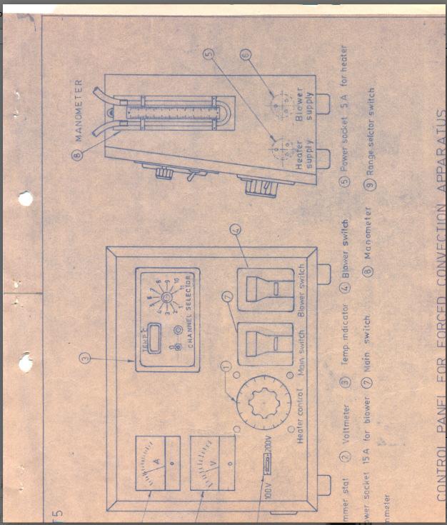
40 EXPERIMENT NO: IX Aim: To determine the heat transfer coefficient in forced convection Apparatus: Standard Forced Convection set up. The apparatus consists of a metal pipe provided with an electric heater. This assembly is covered with insulation so as to avoid any unaccounted heat losses. A blower is fitted to this pipe to provide a constant supply of high velocity air. Thermocouples are provided to measure necessary temperatures. The heater coil is fitted with voltmeter and ammeter. An orifice meter with a U-tube differential type manometer is fitted to measure the velocity of the air. Theory: It is advised that students should write the theory on the subject in their own words under the guidance of the teacher. Procedure: 1) Keep the dimmer-stat at minimum voltage position. Switch ON the electric supply to the heater. 2) Adjust the dimmer-stat to supply a constant voltage to the heating coil. Start the blower supply. 3) Wait for steady state to be attained. 4) Note down the readings in the observation table as given below. Observations: O.D. of the pipe= 32 mm I.D. of the pipe= 28 mm Length of test section= 40 cm Orifice diameter= d= 14 mm Coefficient of discharge= 0.64 Observation Table: Sr. No Voltage (v) Current (A) T 1 T 2 T 3 T 4 T 5 T 6 Manometer reading (mm) Page40
41 Calculations: Page41
42 Page42
43 Result: The heat transfer coefficient in forced convection was found to be w/m 2 K Conclusion: Also expected in this Journal: a. Concept: Heat Transfer in forced convection, Important correlations b. Formulas used: c. Diagrams: i. Set-up ii. Location of the thermocouples Page43
44 EXPERIMENT NO: X Aim: To determine the heat transfer coefficient for natural & forced convection from pin-fin. Apparatus: The apparatus consists of a pin-fin provided with an electric heater at one end. This assembly is kept in a duct and provided with thermocouples along the length. A blower is fitted to this duct to provide a constant supply of high velocity air. This blower is fitted in such a way that its inlet is at the end of the duct. The heater coil is fitted with voltmeter and ammeter. An orifice meter with a U-tube differential type manometer is fitted to the delivery pipe to measure the velocity of the air. Theory: In order to increase the rate of cooling or heating, the heat flow area is increased by attachment of fins or solid materials to the wall of heat exchangers on that side which the coefficient of heat transfer is small. These fins are widely used in engineering heat transfer applications like transformer motors, IC engines, etc.. External surfaces in the form of rods are known as pin fins or spines and one in the form of continuous plates are known as fins. They may be located longitudinally or circumferentially. The cross sectional shape of extended surface in a plane normal to the wall is known as the profile of spine or fin. Procedure: 1) Keep the dimmer-stat to the heater at minimum voltage position. Switch ON the electric supply. 2) Adjust the dimmer-stat to supply a particular voltage to the heater. Maintain this constant throughout the experiment. 3) Wait for steady state to be attained in natural convection mode. 4) Note down the readings in the observation table as given below for natural convection mode. 5) Now turn the blower on. 6) Again, note down the readings in the observation table as given below for forced convection mode. Observations: Density of manometric fluid= 1000 kg/m 3. Diameter of orifice= 15mm. Diameter of pin= 12.7 mm. Duct size= 10x15 cm 2. Coefficient of discharge= Diameter of delivery pipe= 28 mm. Length of pipe= 40 cm. Page44
45 Observation Table: HEAT TRANSFER LABORATORY MANUAL Sr. No. Voltage (v) Current (A) Natural Convection Forced Convection T 1 T 2 T 3 T 4 T 5 T 6 Manometric reading Plot the temperature gradient with the length of the pin. Calculations: Page45
46 Result: Heat transfer coefficient by- 1. Natural convection: a. Experimentally w/m 2 K. b. Theoretically w/m 2 K. 2. Forced convection: a. Experimentally w/m 2 K. b. Theoretically w/m 2 K. Conclusion: Also expected in this Journal: a. Concept: Heat transfer through pin-fin b. Derivation: Heat transfer through pin-fin (All 3 conditions) c. Graph (s): Temperature gradient along the length of fin d. Diagrams: i. Set-up ii. Location of thermocouples Page46
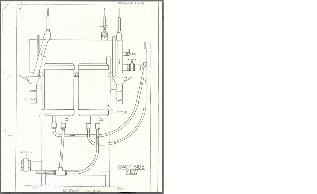
47 EXPERIMENT NO: XI Aim: To determine the following for a shell & tube heat exchangers: I) LMTD II) Effectiveness III) Overall heat transfer coefficients Apparatus: The apparatus consists of a shell & tube type heat exchanger (two pass-tube side). The tube side is supplied with hot water while the cold side with cold water. Thermocouples are provided at the entry & exit of both the water circuits. There is provision of a measuring flask & a stop-watch to measure flow rate on either side. The water is heated with the help of two geysers. Water is continuously supplied o both the circuits. Theory: A device used to transfer heat between fluids that are at different temperatures and separated by a solid wall is termed a heat exchanger. Common uses for heat exchangers are found in waste heat removal, air-conditioning, power production and chemical processing. Heat exchangers may be constructed in different fashions. Common designs incorporate concentric tubes, also known as double-pipe arrangement. This consists of one pipe placed concentrically inside another of larger diameter. This design can have parallel or counter flow configurations. This is largely used for sensible heating or cooling process fluids where small heat transfer rates are required. Other designs incorporate a shell-in-tube construction. Shell and Tube Heat Exchangers They are built of round tubes mounted in large cylindrical shells with the tube axis parallel to the shell. They are widely used as oil coolers, power condensers, preheaters in power plants and steam generators in nuclear power plants. Specific shell and tube designs differ by the number of shell and tube passes. Baffles are commonly used in heat exchangers to increase the convection coefficient. Resistance to Heat Transfer The ability to transfer heat from one fluid to another through some form of solid wall is dependent on a variety of factors: Surface area between the two fluids. Rate of heat transfer through a dividing wall which separates the two fluids. Rate of heat transfer from one layer to the next (if more than one layer is present) in the dividing wall. Rate of heat transfer from the hot fluid to the dividing wall. Rate of heat transfer from the dividing wall to the cold fluid. Surface Area Increasing a common surface area between two fluids will increase overall heat transfer rate between the fluids. This could be accomplished by incorporating more tubes in a shell and tube heat exchanger. Page47
48 Typical Values for Overall Heat Transfer U are- Plate Heat Exchanger, liquid to liquid U range Wm -2 K -1 Shell and tube, liquid inside and outside tubes U range Wm -2 K -1 Spiral Heat Exchanger, liquid to liquid U range Wm -2 K -1 The general representation of a heat exchanger is as shown in the figure below. U= Overall heat transfer coefficient Wm -2 K -1 A= Heat Exchanger Surface Area m 2 h 1 =Heat transfer coefficient-hot side (Wm -2 K -1 ) h 2 = Heat transfer coefficient-cold side (Wm -2 K -1 ) t=temperature ( o C) θ=temperature difference ( o C) Overall Heat Transfer Coefficient For a hollow cylinder exposed to a convection environment on its inner and outer surfaces, the electrical resistance analogy would appear as in the following figure, where, again T A and T B are the two fluid temperatures. Note that the area for convection is not the same in both fluids in this case, these areas depending on the inside tube diameter and the wall thickness. In this case, the overall heat transfer would be expressed by In accordance with the thermal network shown in the figure, the terms A i and A O represent the inside and outside surface areas of the inner tube. The overall heat transfer coefficient may be based on either the inside or the outside area of the tube. Accordingly, Fouling Factors After a period of operation, the heat transfer surfaces for a heat exchanger may become coated with various deposits present in the flow systems or the surfaces may become corroded as a result of the interaction between the fluids and the material used for construction of heat exchanger. In either event, this coating represents a additional resistance to the heat flow, and thus results in decreased performance. The overall effect is usually represented by a fouling factor or fouling resistance R f, which must be included with other resistances making up the overall heat transfer coefficient. Page48
49 Logarithmic Mean Temperature Difference For a double pipe heat exchanger with a hot and cold fluid flowing through it, we calculate the heat transfer in the arrangement with a simple formula Q=UA T m Where, U=overall heat transfer coefficient A=surface area for heat transfer consistent with definition of U T m =suitable mean temperature difference across the heat exchanger LMTD is determined by following equation Where the subscripts I and o stand for the inlet and outlet positions and h and c stand for the hot and cold fluids. The above equation is valid for parallel flow heat exchangers. For counter flow heat exchangers, the inlet and outlet temperature values for the cold fluid get reversed in the equation. LMTD Correction Factor For Countercurrent Shell and Tube Heat Exchanger Log Mean Temperature difference (LMTD) is defined for countercurrent heat transfer. A double pipe heat exchanger provides true countercurrent flow. Other equipment geometries will depart from countercurrent flow. When this happens, the effective MTD is lower than the LMTD. A LMTD correction factor has been defined to account for this circumstance. The LMTD correction factor (F) is defined and used as follows : F= (Effective MTD) / (LMTD) Heat Exchange Duty Q = (Overall Coefficient U)*(Area A)*(F)*(LMTD) F is related to heat transfer geometry and temperatures. This section contains formulas for countercurrent multi-tube pass shell and tube heat exchangers. Temperatures And LMTD Definition T 1 = Shell IN t 1 = Tube IN T 2 = Shell OUT t 2 = Tube OUT (1) The definition of LMTD is the same for all heat exchangers. Shell and tube designations are immaterial in this definition. Auxiliary Variables (2) (3) Page49
50 The LMTD correction factor F is obtained from the relevant charts for the values of P & R. Heat Exchanger Effectiveness One way of measuring a heat exchanger s performance is to calculate its effectiveness. The heat exchanger effectiveness is defined as the ratio of the actual heat transfer to the heat transfer attainable in an infinitely long counter-flow exchanger. So, by defining the effectiveness in this way, we have a much simpler expression for our effectiveness: If, for any given exchanger, the effectiveness is known, we can write the heat transfer equation as: q= εcmin(thin-tcin) Procedure: 1) Start the tube-side water-flow. After ensuring that the water is running, start one of the geysers. 2) Start the cold water supply after a while. Keep the flow-rate at the cold water side higher than the hot water side. Maintain both the flows at a moderate level. 3) Wait for steady state to be attained. 4) Note down the reading in the observation table as given below. Observations: 1. Shell a. Inner Diameter = 208 mm b. Thickness = 6 mm c. Material = M. S. 2. Tubes a. O.D. = 19 mm b. I.D. = 17 mm c. Material = Copper d. Pitch = 30 mm e. No. of tubes = 32 f. Length = 500 mm Page50
51 Observation Table: HEAT TRANSFER LABORATORY MANUAL Sr. No. 1 Flow Rate Shell Side Inlet Temperature Outlet Temperature Flow Rate Tube Side Inlet Temperature Outlet Temperature Calculations: Page51
52 Page52
53 Result: 1) LMTD= C 2) U i actual= W/m 2 K 3) U i theoretical= W/m 2 K 4) U o actual= W/m 2 K 5) U o theoretical= W/m 2 K 6) ε = Conclusion: Also expected in this Journal: a. Concept: Shell & Tube Heat Exchanger, Correlations b. Graph (s): None c. Diagrams: d. Set-up Page53
54 EXPERIMENT NO: XII Aim: To study film wise and drop wise condensation and to determine the overall heat transfer coefficient. Apparatus: Condenser main unit, heating element, steam generator, temperature indicator, rotameter. Theory: Condensaton Heat Transfer: Condensaton heat transfer is a vital process in Process and Power Generation industries and as a result, has been an area of research for over a hundred years. Over this period our understanding of the condensation process has gradually improved. Theories and models have become more accurate and are now applicable to a wider range of conditions. Condensation: There are two modes of condensation, viz., Filmwise and Dropwise. Filmwise is currently usd by industry, while Dropwise is an alternative which is under development because it offers attractive higher rates of heat tranfer by preventing the build up of the insulating liquid layer found in filmwise condensation. Filmwise And Dropwise Condensation: Dropwise and filmwise are the two major forms of condensation. Dropwaise condensation occurs when liquid droplets form on a cold surface and then falls from it, leaving the cold surface dry. Filmwise condensatoon occurs when a film of condensate coats the cold surface. This is the most commen form of condensation. The only pure vapour known to condense in a dropwise manner is steam. Dropwise condensation is more difficult to create and maintain. It is important to note that there are significant differences between these two types of condensation. Due to the resistance of heat passing through condensate film, the heat-transfer coefficients for dropwise condensation are 4-8 times greater than those for filmwise condensation. All but a few precious metals will in an untreated state tend to condensate filmwise; this is why industrial condensors currently operate filmwise. This type of condensatio behaviour which a metal displays, is related to its surface energy. Materials with a high surface energy condensate filmwise, while those with a low surface energy condensate dropwise. With suitable promoters or surface treatments, most metals, including those with high surface energies, can promote dropwise condensation. Page54

55 Procedure: 1. Fill the steam generator with water. 2. Start the water flow through one of the condensers which is to be tested and note down the water flow rate in the rotameter. Ensure that during the measurement of flow rate water is flowing through only the condenser under test and second valve is closed. Note the flow rate of the water. 3. Switch ON the heater. 4. Slowly steam generation will begin in the steam generator. As the steam rises to the last section, it gets condensed & flows down in the cylinder. 5. Depending upon the type of condenser under test, dropwise or filmwise condensation can be visualized. 6. Note down the temperatures of the water, steam and the surface of the condenser. Observations: Inner diameter of the tube= 17 mm. Outer diameter of the tube= 20 mm. Length of tube= 140 mm. Page55
If there is convective heat transfer from outer surface to fluid maintained at T W.
 Heat Transfer 1. What are the different modes of heat transfer? Explain with examples. 2. State Fourier s Law of heat conduction? Write some of their applications. 3. State the effect of variation of temperature
Heat and Mass Transfer Unit-1 Conduction
 1. State Fourier s Law of conduction. Heat and Mass Transfer Unit-1 Conduction Part-A The rate of heat conduction is proportional to the area measured normal to the direction of heat flow and to the temperature
Experiment 1. Measurement of Thermal Conductivity of a Metal (Brass) Bar
 Bar") Experiment 1 Measurement of Thermal Conductivity of a Metal (Brass) Bar Introduction: Thermal conductivity is a measure of the ability of a substance to conduct heat, determined by the rate of heat flow
Experiment 1 Measurement of Thermal Conductivity of a Metal (Brass) Bar Introduction: Thermal conductivity is a measure of the ability of a substance to conduct heat, determined by the rate of heat flow
LAB MANNUAL HEAT TRANSFER
 LAB MANNUAL OF HEAT TRANSFER (ME- 316E) DEPTT. OF MECHANICAL ENGINEERING OM INSTITUTE OF TECHNOLOGY & MANAGEMENT 12km Stone, NH-65, Chandigarh Road Juglan (Hisar) Web Site-www.oitmhisar.com, Email:- oitm_hsr@yahoo.com,
Latest Heat Transfer
 Latest Heat Transfer 1. Unit of thermal conductivity in M.K.S. units is (a) kcal/kg m2 C (b) kcal-m/hr m2 C (c) kcal/hr m2 C (d) kcal-m/hr C (e) kcal-m/m2 C. 2. Unit of thermal conductivity in S.I. units
HEAT TRANSFER 1 INTRODUCTION AND BASIC CONCEPTS 5 2 CONDUCTION
 HEAT TRANSFER 1 INTRODUCTION AND BASIC CONCEPTS 5 2 CONDUCTION 11 Fourier s Law of Heat Conduction, General Conduction Equation Based on Cartesian Coordinates, Heat Transfer Through a Wall, Composite Wall
S.E. (Chemical) (Second Semester) EXAMINATION, 2012 HEAT TRANSFER (2008 PATTERN) Time : Three Hours Maximum Marks : 100
 (Second Semester) EXAMINATION, 2012 HEAT TRANSFER (2008 PATTERN) Time : Three Hours Maximum Marks : 100") Total No. of Questions 12] [Total No. of Printed Pages 7 Seat No. [4162]-187 S.E. (Chemical) (Second Semester) EXAMINATION, 2012 HEAT TRANSFER (2008 PATTERN) Time : Three Hours Maximum Marks : 100 N.B.
Total No. of Questions 12] [Total No. of Printed Pages 7 Seat No. [4162]-187 S.E. (Chemical) (Second Semester) EXAMINATION, 2012 HEAT TRANSFER (2008 PATTERN) Time : Three Hours Maximum Marks : 100 N.B.
Principles of Food and Bioprocess Engineering (FS 231) Problems on Heat Transfer
 Problems on Heat Transfer") Principles of Food and Bioprocess Engineering (FS 1) Problems on Heat Transfer 1. What is the thermal conductivity of a material 8 cm thick if the temperature at one end of the product is 0 C and the temperature
Principles of Food and Bioprocess Engineering (FS 1) Problems on Heat Transfer 1. What is the thermal conductivity of a material 8 cm thick if the temperature at one end of the product is 0 C and the temperature
Examination Heat Transfer
 Examination Heat Transfer code: 4B680 date: 17 january 2006 time: 14.00-17.00 hours NOTE: There are 4 questions in total. The first one consists of independent sub-questions. If necessary, guide numbers
HEAT AND MASS TRANSFER. List of Experiments:
 HEAT AND MASS TRANSFER List of Experiments: Conduction Heat Transfer Unit 1. Investigation of Fourier Law for linear conduction of heat along a simple bar. 2. Study the conduction of heat along a composite
INDEX. Determination of overall heat transfer coefficient of Composite Wall. Determination of over all heat transfer coefficient of Lagged Pipe
 HEAT TRANSFER LAB INDEX S.No. NAME OF EXPERIMENT PAGE No. 1 Determination of Thermal conductivity of insulation powder 2 Determination of overall heat transfer coefficient of Composite Wall 3 Determination
SHRI RAMSWAROOP MEMORIAL COLLEGE OF ENGG. & MANAGEMENT B.Tech. [SEM V (ME-51, 52, 53, 54)] QUIZ TEST-1 (Session: )
![SHRI RAMSWAROOP MEMORIAL COLLEGE OF ENGG. & MANAGEMENT B.Tech. [SEM V (ME-51, 52, 53, 54)] QUIZ TEST-1 (Session: )](/thumbs/78/78353407.jpg "SHRI RAMSWAROOP MEMORIAL COLLEGE OF ENGG. & MANAGEMENT B.Tech. [SEM V (ME-51, 52, 53, 54)] QUIZ TEST-1 (Session: )") QUIZ TEST-1 Time: 1 Hour HEAT AND MASS TRANSFER Note: All questions are compulsory. Q1) The inside temperature of a furnace wall ( k=1.35w/m.k), 200mm thick, is 1400 0 C. The heat transfer coefficient
QUIZ TEST-1 Time: 1 Hour HEAT AND MASS TRANSFER Note: All questions are compulsory. Q1) The inside temperature of a furnace wall ( k=1.35w/m.k), 200mm thick, is 1400 0 C. The heat transfer coefficient
LABORATORY MANNUAL HEAT TRANSFER LAB ME-316-F. BRCM College of Engineering & Technology Bahal
 LABORATORY MANNUAL HEAT TRANSFER LAB ME-316-F BRCM College of Engineering & Technology Bahal 0 E- 316 F HEAT TRANSFER LAB. L T P Sessional : 50 Marks - - - 3 Practical : 50 Marks Total : 100 Marks Duration
Introduction to Heat Transfer
 Question Bank CH302 Heat Transfer Operations Introduction to Heat Transfer Question No. 1. The essential condition for the transfer of heat from one body to another (a) Both bodies must be in physical
HEAT TRANSFER. PHI Learning PfcO too1. Principles and Applications BINAY K. DUTTA. Delhi Kolkata. West Bengal Pollution Control Board
 HEAT TRANSFER Principles and Applications BINAY K. DUTTA West Bengal Pollution Control Board Kolkata PHI Learning PfcO too1 Delhi-110092 2014 Contents Preface Notations ix xiii 1. Introduction 1-8 1.1
Thermal Systems. What and How? Physical Mechanisms and Rate Equations Conservation of Energy Requirement Control Volume Surface Energy Balance
 Introduction to Heat Transfer What and How? Physical Mechanisms and Rate Equations Conservation of Energy Requirement Control Volume Surface Energy Balance Thermal Resistance Thermal Capacitance Thermal
C ONTENTS CHAPTER TWO HEAT CONDUCTION EQUATION 61 CHAPTER ONE BASICS OF HEAT TRANSFER 1 CHAPTER THREE STEADY HEAT CONDUCTION 127
 C ONTENTS Preface xviii Nomenclature xxvi CHAPTER ONE BASICS OF HEAT TRANSFER 1 1-1 Thermodynamics and Heat Transfer 2 Application Areas of Heat Transfer 3 Historical Background 3 1-2 Engineering Heat
S.E. (Chemical) (Second Semester) EXAMINATION, 2011 HEAT TRANSFER (2008 PATTERN) Time : Three Hours Maximum Marks : 100
 (Second Semester) EXAMINATION, 2011 HEAT TRANSFER (2008 PATTERN) Time : Three Hours Maximum Marks : 100") Total No. of Questions 12] [Total No. of Printed Pages 7 [4062]-186 S.E. (Chemical) (Second Semester) EXAMINATION, 2011 HEAT TRANSFER (2008 PATTERN) Time : Three Hours Maximum Marks : 100 N.B. : (i) Answers
Total No. of Questions 12] [Total No. of Printed Pages 7 [4062]-186 S.E. (Chemical) (Second Semester) EXAMINATION, 2011 HEAT TRANSFER (2008 PATTERN) Time : Three Hours Maximum Marks : 100 N.B. : (i) Answers
ME6512-THERMAL ENGINEERING LAB-II VARUVAN VADIVELAN INSTITUTE OF TECHNOLOGY DHARMAPURI DEPARTMENT OF MECHANICAL ENGINEERING
 VARUVAN VADIVELAN INSTITUTE OF TECHNOLOGY DHARMAPURI 636 703 DEPARTMENT OF MECHANICAL ENGINEERING REG NO THERMAL ENGINEERING II LAB MANUAL NAME SUBJECT CODE\TITLE ME 6512 - THERMAL ENGINEERING LABORATORY
Solar Flat Plate Thermal Collector
 Solar Flat Plate Thermal Collector INTRODUCTION: Solar heater is one of the simplest and basic technologies in the solar energy field. Collector is the heart of any solar heating system. It absorbs and
TEMPERATURE. 8. Temperature and Heat 1
 TEMPERATURE Heat is the energy that is transferred between objects because of a temperature difference Terms such as transfer of heat or heat flow from object A to object B simply means that the total
CHAPTER 5 CONVECTIVE HEAT TRANSFER COEFFICIENT
 62 CHAPTER 5 CONVECTIVE HEAT TRANSFER COEFFICIENT 5.1 INTRODUCTION The primary objective of this work is to investigate the convective heat transfer characteristics of silver/water nanofluid. In order
: HEAT TRANSFER & EVAPORATION COURSE CODE : 4072 COURSE CATEGORY : B PERIODS/ WEEK : 5 PERIODS/ SEMESTER : 70 CREDIT : 5 TIME SCHEDULE
 COURSE TITLE : HEAT TRANSFER & EVAPORATION COURSE CODE : 4072 COURSE CATEGORY : B PERIODS/ WEEK : 5 PERIODS/ SEMESTER : 70 CREDIT : 5 TIME SCHEDULE MODULE TOPIC PERIODS 1 Conduction,Fourier law,variation
HEAT TRANSFER AND EXCHANGERS
 HEAT TRANSFER AND EXCHANGERS Although heat-transfer rates can be computed with reasonable accuracy for clean or new pipe, the effect of dirty or corroded pipe surfaces cannot he satisfactorily estimated.
LECTURE NOTES. Heat Transfer. III B. Tech II Semester (JNTUA-R15) CHADALAWADA RAMANAMMA ENGINEERING COLLEGE (AUTONOMOUS)
 CHADALAWADA RAMANAMMA ENGINEERING COLLEGE (AUTONOMOUS)") LECTURE NOTES on Heat Transfer III B. Tech II Semester (JNTUA-R15) Mr. K.SURESH, Assistant Professor CHADALAWADA RAMANAMMA ENGINEERING COLLEGE (AUTONOMOUS) Chadalawada Nagar, Renigunta Road, Tirupati 517
LECTURE NOTES on Heat Transfer III B. Tech II Semester (JNTUA-R15) Mr. K.SURESH, Assistant Professor CHADALAWADA RAMANAMMA ENGINEERING COLLEGE (AUTONOMOUS) Chadalawada Nagar, Renigunta Road, Tirupati 517
1. How much heat was needed to raise the bullet to its final temperature?
 Name: Date: Use the following to answer question 1: A 0.0500-kg lead bullet of volume 5.00 10 6 m 3 at 20.0 C hits a block that is made of an ideal thermal insulator and comes to rest at its center. At
PAPER 2 THEORY QUESTIONS
 PAPER 2 THEORY QUESTIONS 1 Fig. 1.1 shows the arrangement of atoms in a solid block. Fig. 1.1 (a) End X of the block is heated. Energy is conducted to end Y, which becomes warm. (i) Explain how heat is
Applied Thermodynamics HEAT TRANSFER. Introduction What and How?
 LANDMARK UNIVERSITY, OMU-ARAN LECTURE NOTE: 3 COLLEGE: COLLEGE OF SCIENCE AND ENGINEERING DEPARTMENT: MECHANICAL ENGINEERING PROGRAMME: ENGR. ALIYU, S.J Course code: MCE 311 Course title: Applied Thermodynamics
Chapter 9 NATURAL CONVECTION
 Heat and Mass Transfer: Fundamentals & Applications Fourth Edition in SI Units Yunus A. Cengel, Afshin J. Ghajar McGraw-Hill, 2011 Chapter 9 NATURAL CONVECTION PM Dr Mazlan Abdul Wahid Universiti Teknologi
Chapter 1 INTRODUCTION AND BASIC CONCEPTS
 Heat and Mass Transfer: Fundamentals & Applications 5th Edition in SI Units Yunus A. Çengel, Afshin J. Ghajar McGraw-Hill, 2015 Chapter 1 INTRODUCTION AND BASIC CONCEPTS Mehmet Kanoglu University of Gaziantep
P5 Heat and Particles Revision Kinetic Model of Matter: States of matter
 P5 Heat and Particles Revision Kinetic Model of Matter: States of matter State Size Shape Solid occupies a fixed volume has a fixed shape Liquid occupies a fixed volume takes the shape of its container
Chapter 3 NATURAL CONVECTION
 Fundamentals of Thermal-Fluid Sciences, 3rd Edition Yunus A. Cengel, Robert H. Turner, John M. Cimbala McGraw-Hill, 2008 Chapter 3 NATURAL CONVECTION Mehmet Kanoglu Copyright The McGraw-Hill Companies,
ELEC9712 High Voltage Systems. 1.2 Heat transfer from electrical equipment
 ELEC9712 High Voltage Systems 1.2 Heat transfer from electrical equipment The basic equation governing heat transfer in an item of electrical equipment is the following incremental balance equation, with
COVENANT UNIVERSITY NIGERIA TUTORIAL KIT OMEGA SEMESTER PROGRAMME: MECHANICAL ENGINEERING
 COVENANT UNIVERSITY NIGERIA TUTORIAL KIT OMEGA SEMESTER PROGRAMME: MECHANICAL ENGINEERING COURSE: MCE 524 DISCLAIMER The contents of this document are intended for practice and leaning purposes at the
HEAT TRANSFER LAB MANUAL
 HEAT TRANSFER LAB MANUAL NIRMA UNIVERSITY INSTITUTE OF TECHNOLOGY CHEMICAL ENGINEERING DEPARTMENT List of Experiments: 1. Thermal conductivity apparatus 2. Thermal conductivity of metal rod 3. Thermal
Resistivity and Temperature Coefficients (at 20 C)
") Homework # 4 Resistivity and Temperature Coefficients (at 0 C) Substance Resistivity, Temperature ( m) Coefficient, (C ) - Conductors Silver.59 x 0-0.006 Copper.6 x 0-0.006 Aluminum.65 x 0-0.0049 Tungsten
Homework # 4 Resistivity and Temperature Coefficients (at 0 C) Substance Resistivity, Temperature ( m) Coefficient, (C ) - Conductors Silver.59 x 0-0.006 Copper.6 x 0-0.006 Aluminum.65 x 0-0.0049 Tungsten
Chapter 11. Energy in Thermal Processes
 Chapter 11 Energy in Thermal Processes Energy Transfer When two objects of different temperatures are placed in thermal contact, the temperature of the warmer decreases and the temperature of the cooler
TRANSMISSION OF HEAT
 TRANSMISSION OF HEAT Synopsis :. In general heat travels from one point to another whenever there is a difference of temperatures.. Heat flows from a body at higher temperature to a lower temperature..
Heat and Mass Transfer Prof. S.P. Sukhatme Department of Mechanical Engineering Indian Institute of Technology, Bombay
 Heat and Mass Transfer Prof. S.P. Sukhatme Department of Mechanical Engineering Indian Institute of Technology, Bombay Lecture No. 18 Forced Convection-1 Welcome. We now begin our study of forced convection
Thermal Analysis. with SolidWorks Simulation 2013 SDC. Paul M. Kurowski. Better Textbooks. Lower Prices.
 Thermal Analysis with SolidWorks Simulation 2013 Paul M. Kurowski SDC PUBLICATIONS Schroff Development Corporation Better Textbooks. Lower Prices. www.sdcpublications.com Visit the following websites to
Unit 11: Temperature and heat
 Unit 11: Temperature and heat 1. Thermal energy 2. Temperature 3. Heat and thermal equlibrium 4. Effects of heat 5. Transference of heat 6. Conductors and insulators Think and answer a. Is it the same
Jawaharlal Nehru Engineering College
 Jawaharlal Nehru Engineering College Laboratory Manual For MOMENTUM TRANSFER Second Year Students Chemical Engineering Author JNEC, Aurangabad FORWARD It is my great pleasure to present this laboratory
Physics 111. Lecture 36 (Walker: ) Heat Capacity & Specific Heat Heat Transfer. May 1, Quiz (Chaps. 14 & 16) on Wed.
 Heat Capacity & Specific Heat Heat Transfer. May 1, Quiz (Chaps. 14 & 16) on Wed.") Physics 111 Lecture 36 (Walker: 16.4-6) Heat Capacity & Specific Heat Heat Transfer May 1, 2009 Quiz (Chaps. 14 & 16) on Wed. May 6 Lecture 36 1/26 Heat Capacity (C) The heat capacity C of an object is
Physics 111 Lecture 36 (Walker: 16.4-6) Heat Capacity & Specific Heat Heat Transfer May 1, 2009 Quiz (Chaps. 14 & 16) on Wed. May 6 Lecture 36 1/26 Heat Capacity (C) The heat capacity C of an object is
Lecture 28. Key words: Heat transfer, conduction, convection, radiation, furnace, heat transfer coefficient
 Lecture 28 Contents Heat transfer importance Conduction Convection Free Convection Forced convection Radiation Radiation coefficient Illustration on heat transfer coefficient 1 Illustration on heat transfer
Pin Fin Lab Report Example. Names. ME331 Lab
 Pin Fin Lab Report Example Names ME331 Lab 04/12/2017 1. Abstract The purposes of this experiment are to determine pin fin effectiveness and convective heat transfer coefficients for free and forced convection
INSTRUCTOR: PM DR MAZLAN ABDUL WAHID
 SMJ 4463: HEAT TRANSFER INSTRUCTOR: PM DR MAZLAN ABDUL WAHID http://www.fkm.utm.my/~mazlan TEXT: Introduction to Heat Transfer by Incropera, DeWitt, Bergman, Lavine 5 th Edition, John Wiley and Sons DR
Chapter 1 Heating Processes
 Chapter 1 Heating Processes Section 1.1 Heat and temperature Worked example: Try yourself 1.1.1 CALCULATING THE CHANGE IN INTERNAL ENERGY A student places a heating element and a paddle wheel apparatus
Chapter 11: Heat Exchangers. Dr Ali Jawarneh Department of Mechanical Engineering Hashemite University
 Chapter 11: Heat Exchangers Dr Ali Jawarneh Department of Mechanical Engineering Hashemite University Objectives When you finish studying this chapter, you should be able to: Recognize numerous types of
Introduction to Heat and Mass Transfer. Week 5
 Introduction to Heat and Mass Transfer Week 5 Critical Resistance Thermal resistances due to conduction and convection in radial systems behave differently Depending on application, we want to either maximize
Ministry of Higher Education And Scientific Research. University Of Technology Chemical Engineering Department. Heat Transfer
 Ministry of Higher Education And Scientific Research University Of Technology Heat Transfer Third Year By Dr.Jamal Al-Rubeai 2008-2009 Heat Transfer 1. Modes of Heat Transfer: Conduction, Convection and
Arctice Engineering Module 3a Page 1 of 32
 Welcome back to the second part of the second learning module for Fundamentals of Arctic Engineering online. We re going to review in this module the fundamental principles of heat transfer. Exchange of
INTRODUCTION: Shell and tube heat exchangers are one of the most common equipment found in all plants. How it works?
 HEAT EXCHANGERS 1 INTRODUCTION: Shell and tube heat exchangers are one of the most common equipment found in all plants How it works? 2 WHAT ARE THEY USED FOR? Classification according to service. Heat
1. Nusselt number and Biot number are computed in a similar manner (=hd/k). What are the differences between them? When and why are each of them used?
. What are the differences between them? When and why are each of them used?") 1. Nusselt number and Biot number are computed in a similar manner (=hd/k). What are the differences between them? When and why are each of them used?. During unsteady state heat transfer, can the temperature
1. Nusselt number and Biot number are computed in a similar manner (=hd/k). What are the differences between them? When and why are each of them used?. During unsteady state heat transfer, can the temperature
Exergy Analysis of Solar Air Collector Having W Shaped Artificial Roughness
 Advances in Materials Science and Mechanical Engineering Research Volume 1, Number 1 (2015), pp. 25-32 International Research Publication House http://www.irphouse.com Exergy Analysis of Solar Air Collector
PH2200 Practice Final Exam Summer 2003
 INSTRUCTIONS 1. Write your name and student identification number on the answer sheet. 2. Please cover your answer sheet at all times. 3. This is a closed book exam. You may use the PH2200 formula sheet
 Unit II Thermal Physics Introduction- Modes of Heat Transfer Normally there are three modes of transfer of heat from one place to another viz., conduction, convection and radiation. Conduction : Conduction
GUJARAT TECHNOLOGICAL UNIVERSITY, AHMEDABAD, GUJARAT. COURSE CURRICULUM COURSE TITLE: PROCESS HEAT TRANSFER (Course Code: )
") GUJARAT TECHNOLOGICAL UNIVERSITY, AHMEDABAD, GUJARAT COURSE CURRICULUM COURSE TITLE: PROCESS HEAT TRANSFER (Course Code: 330501) Diploma Programme in which this course is offered Chemical Engineering Semester
GUJARAT TECHNOLOGICAL UNIVERSITY, AHMEDABAD, GUJARAT COURSE CURRICULUM COURSE TITLE: PROCESS HEAT TRANSFER (Course Code: 330501) Diploma Programme in which this course is offered Chemical Engineering Semester
Name Class Date. What are three kinds of energy transfer? What are conductors and insulators? What makes something a good conductor of heat?
 CHAPTER 14 SECTION Heat and Temperature 2 Energy Transfer KEY IDEAS As you read this section, keep these questions in mind: What are three kinds of energy transfer? What are conductors and insulators?
Tutorial 1. Where Nu=(hl/k); Reynolds number Re=(Vlρ/µ) and Prandtl number Pr=(µCp/k)
; Reynolds number Re=(Vlρ/µ) and Prandtl number Pr=(µCp/k)") Tutorial 1 1. Explain in detail the mechanism of forced convection. Show by dimensional analysis (Rayleigh method) that data for forced convection may be correlated by an equation of the form Nu = φ (Re,
Tutorial 1 1. Explain in detail the mechanism of forced convection. Show by dimensional analysis (Rayleigh method) that data for forced convection may be correlated by an equation of the form Nu = φ (Re,
UNIT II CONVECTION HEAT TRANSFER
 UNIT II CONVECTION HEAT TRANSFER Convection is the mode of heat transfer between a surface and a fluid moving over it. The energy transfer in convection is predominately due to the bulk motion of the fluid
PHYS102 Previous Exam Problems. Temperature, Heat & The First Law of Thermodynamics
 PHYS102 Previous Exam Problems CHAPTER 18 Temperature, Heat & The First Law of Thermodynamics Equilibrium & temperature scales Thermal expansion Exchange of heat First law of thermodynamics Heat conduction
Module 8: BoiIing Lecture 29: Boiling Heat Transfer. The Lecture Contains: Introduction. Boiling modes. Pool Boiling. Correlations in Pool Boiling
 The Lecture Contains: Introduction Boiling modes Pool Boiling Correlations in Pool Boiling file:///d /Web%20Course%20(Ganesh%20Rana)/Dr.%20gautam%20biswas/Final/convective_heat_and_mass_transfer/lecture29/29_1.html[12/24/2014
Fatima
 Fatima QUESTION BANK DEPARTMENT: MECH SEMESTER: IV SUBJECT CODE / Name: ME 2251/HEAT AND MASS TRANSFER UNIT I: CONDUCTION PART -A (2 Marks) 1. What is Fourier's Law of heat conduction? (May 05, May 06,
Mechanical Engineering. Postal Correspondence Course HEAT TRANSFER. GATE, IES & PSUs
 Heat Transfer-ME GATE, IES, PSU 1 SAMPLE STUDY MATERIAL Mechanical Engineering ME Postal Correspondence Course HEAT TRANSFER GATE, IES & PSUs Heat Transfer-ME GATE, IES, PSU 2 C O N T E N T 1. INTRODUCTION
Heat Tracing Basics. By: Homi R. Mullan 1
 Heat Tracing Basics By: Homi R. Mullan 1 Heat Tracing Basics Topics of Discussion What is Heat Tracing? Why Heat Tracing? Fundamentals of Heat Loss and Heat Replenishment Rules to Remember in the Heat
Heat Transfer Modeling using ANSYS FLUENT
 Lecture 1 - Introduction 14.5 Release Heat Transfer Modeling using ANSYS FLUENT 2013 ANSYS, Inc. March 28, 2013 1 Release 14.5 Outline Modes of Heat Transfer Basic Heat Transfer Phenomena Conduction Convection
TOPIC 2 [A] STEADY STATE HEAT CONDUCTION
![TOPIC 2 [A] STEADY STATE HEAT CONDUCTION](/thumbs/96/128741039.jpg "TOPIC 2 [A] STEADY STATE HEAT CONDUCTION") TOPIC 2 [A] STEADY STATE HEAT CONDUCTION CLASS TUTORIAL 1. The walls of a refrigerated truck consist of 1.2 mm thick steel sheet (k=18 W/m-K) at the outer surface, 22 mm thick cork (k=0.04 W/m-K) on the
TOPIC 2 [A] STEADY STATE HEAT CONDUCTION CLASS TUTORIAL 1. The walls of a refrigerated truck consist of 1.2 mm thick steel sheet (k=18 W/m-K) at the outer surface, 22 mm thick cork (k=0.04 W/m-K) on the
Heriot-Watt University
 Heriot-Watt University Distinctly Global www.hw.ac.uk Thermodynamics By Peter Cumber Prerequisites Interest in thermodynamics Some ability in calculus (multiple integrals) Good understanding of conduction
Coolant. Circuits Chip
 1) A square isothermal chip is of width w=5 mm on a side and is mounted in a subtrate such that its side and back surfaces are well insulated, while the front surface is exposed to the flow of a coolant
Chapter: Heat and States
 Table of Contents Chapter: Heat and States of Matter Section 1: Temperature and Thermal Energy Section 2: States of Matter Section 3: Transferring Thermal Energy Section 4: Using Thermal Energy 1 Temperature
Exam questions: HEAT. 2. [2003 OL][2004 OL][2005 OL][2006 OL][2007 OL][2008 OL][2009] Name two methods by which heat can be transferred.
![Exam questions: HEAT. 2. [2003 OL][2004 OL][2005 OL][2006 OL][2007 OL][2008 OL][2009] Name two methods by which heat can be transferred.](/thumbs/87/96755378.jpg "Exam questions: HEAT. 2. [2003 OL][2004 OL][2005 OL][2006 OL][2007 OL][2008 OL][2009] Name two methods by which heat can be transferred.") Exam questions: HEAT Specific heat capacity of copper = 390 J kg 1 K 1 ; Specific heat capacity of water = 4200 J kg 1 K 1 s.h.c. of aluminium = 910 J kg -1 K -1 ; Specific latent heat of fusion of ice
Exam questions: HEAT Specific heat capacity of copper = 390 J kg 1 K 1 ; Specific heat capacity of water = 4200 J kg 1 K 1 s.h.c. of aluminium = 910 J kg -1 K -1 ; Specific latent heat of fusion of ice
Autumn 2005 THERMODYNAMICS. Time: 3 Hours
 CORK INSTITUTE OF TECHNOOGY Bachelor of Engineering (Honours) in Mechanical Engineering Stage 3 (Bachelor of Engineering in Mechanical Engineering Stage 3) (NFQ evel 8) Autumn 2005 THERMODYNAMICS Time:
AN EXPERIMENTAL INVESTIGATION OF BOILING HEAT CONVECTION WITH RADIAL FLOW IN A FRACTURE
 PROCEEDINGS, Twenty-Fourth Workshop on Geothermal Reservoir Engineering Stanford University, Stanford, California, January 25-27, 1999 SGP-TR-162 AN EXPERIMENTAL INVESTIGATION OF BOILING HEAT CONVECTION
Phone: , For Educational Use. SOFTbank E-Book Center, Tehran. Fundamentals of Heat Transfer. René Reyes Mazzoco
 8 Fundamentals of Heat Transfer René Reyes Mazzoco Universidad de las Américas Puebla, Cholula, Mexico 1 HEAT TRANSFER MECHANISMS 1.1 Conduction Conduction heat transfer is explained through the molecular
True/False. Circle the correct answer. (1pt each, 7pts total) 3. Radiation doesn t occur in materials that are transparent such as gases.
 3. Radiation doesn t occur in materials that are transparent such as gases.") ME 323 Sample Final Exam. 120pts total True/False. Circle the correct answer. (1pt each, 7pts total) 1. A solid angle of 2π steradians defines a hemispherical shell. T F 2. The Earth irradiates the Sun.
ME 323 Sample Final Exam. 120pts total True/False. Circle the correct answer. (1pt each, 7pts total) 1. A solid angle of 2π steradians defines a hemispherical shell. T F 2. The Earth irradiates the Sun.
4.1. Physics Module Form 4 Chapter 4 - Heat GCKL UNDERSTANDING THERMAL EQUILIBRIUM. What is thermal equilibrium?
 Physics Module Form 4 Chapter 4 - Heat GCKL 2010 4.1 4 UNDERSTANDING THERMAL EQUILIBRIUM What is thermal equilibrium? 1. (, Temperature ) is a form of energy that flows from a hot body to a cold body.
Thermo-Hydraulic performance of Internal finned tube Automobile Radiator
 Thermo-Hydraulic performance of Internal finned tube Automobile Radiator Dr.Kailash Mohapatra 1, Deepiarani Swain 2 1 Department of Mechanical Engineering, Raajdhani Engineering College, Bhubaneswar, 751017,
Heat Transfer Predictions for Carbon Dioxide in Boiling Through Fundamental Modelling Implementing a Combination of Nusselt Number Correlations
 Heat Transfer Predictions for Carbon Dioxide in Boiling Through Fundamental Modelling Implementing a Combination of Nusselt Number Correlations L. Makaum, P.v.Z. Venter and M. van Eldik Abstract Refrigerants
Handout 10: Heat and heat transfer. Heat capacity
 1 Handout 10: Heat and heat transfer Heat capacity Consider an experiment in Figure 1. Heater is inserted into a solid substance of mass m and the temperature rise T degrees Celsius is measured by a thermometer.
IJSRD - International Journal for Scientific Research & Development Vol. 3, Issue 06, 2015 ISSN (online):
:") IJSRD - International Journal for Scientific Research & Development Vol. 3, Issue 06, 2015 ISSN (online): 2321-0613 Experimental Investigation for Enhancement of Heat Transfer in Two Pass Solar Air Heater
IJSRD - International Journal for Scientific Research & Development Vol. 3, Issue 06, 2015 ISSN (online): 2321-0613 Experimental Investigation for Enhancement of Heat Transfer in Two Pass Solar Air Heater
Thermal Analysis with SOLIDWORKS Simulation 2015 and Flow Simulation 2015
 Thermal Analysis with SOLIDWORKS Simulation 2015 and Flow Simulation 2015 Paul M. Kurowski SDC PUBLICATIONS Better Textbooks. Lower Prices. www.sdcpublications.com Powered by TCPDF (www.tcpdf.org) Visit
TankExampleNov2016. Table of contents. Layout
 Table of contents Task... 2 Calculation of heat loss of storage tanks... 3 Properties ambient air Properties of air... 7 Heat transfer outside, roof Heat transfer in flow past a plane wall... 8 Properties
DESIGN AND COST ANALYSIS OF HEAT TRANSFER EQUIPMENTS
 DESIGN AND COST ANALYSIS OF HEAT TRANSFER EQUIPMENTS Md. Khairul Islam Lecturer Department of Applied Chemistry and Chemical Engineering. University of Rajshahi. What is design? Design includes all the
AP Physics 2: Algebra-Based
 2018 AP Physics 2: Algebra-Based Scoring Guidelines College Board, Advanced Placement Program, AP, AP Central, and the acorn logo are registered trademarks of the College Board. AP Central is the official
Overall Heat Transfer Coefficient
 Overall Heat Transfer Coefficient A heat exchanger typically involves two flowing fluids separated by a solid wall. Heat is first transferred from the hot fluid to the wall by convection, through the wall
Chapter 11. Energy in Thermal Processes
 Chapter 11 Energy in Thermal Processes Energy Transfer When two objects of different temperatures are placed in thermal contact, the temperature of the warmer decreases and the temperature of the cooler
DEPARTMENT OF MECHANICAL ENGINEERING. ME 6502 Heat and Mass Transfer III YEAR-V SEMESTER
 ME650 HEAT AND MASS TRNSFER MARKS & 16 MARKS QUESTION AND ANSWER ME 650 Heat and Mass Transfer III YEAR-V SEMESTER NAME :. REG.NO :. BRANCH :... YEAR & SEM :. 1 ME650 HEAT AND MASS TRNSFER MARKS & 16 MARKS
Two point charges, A and B, lie along a line separated by a distance L. The point x is the midpoint of their separation.
 Use the following to answer question 1. Two point charges, A and B, lie along a line separated by a distance L. The point x is the midpoint of their separation. 1. Which combination of charges would yield
Level 7 Post Graduate Diploma in Engineering Heat and mass transfer
 9210-221 Level 7 Post Graduate Diploma in Engineering Heat and mass transfer 0 You should have the following for this examination one answer book non programmable calculator pen, pencil, drawing instruments
ICSE Board Class IX Physics Paper 2 Solution
 ICSE Board Class IX Physics Paper 2 Solution SECTION I Answer 1 (a) Unit is a standard quantity of the same kind with which a physical quantity is compared for measuring it. The SI unit of length is meter
University of New Mexico Mechanical Engineering Fall 2012 PhD qualifying examination Heat Transfer
 University of New Mexico Mechanical Engineering Fall 2012 PhD qualifying examination Heat Transfer Closed book. Formula sheet and calculator are allowed, but not cell phones, computers or any other wireless
Principles of Food and Bioprocess Engineering (FS 231) Exam 2 Part A -- Closed Book (50 points)
 Exam 2 Part A -- Closed Book (50 points)") Principles of Food and Bioprocess Engineering (FS 231) Exam 2 Part A -- Closed Book (50 points) 1. Are the following statements true or false? (20 points) a. Thermal conductivity of a substance is a measure
Principles of Food and Bioprocess Engineering (FS 231) Exam 2 Part A -- Closed Book (50 points) 1. Are the following statements true or false? (20 points) a. Thermal conductivity of a substance is a measure
15 - THERMAL AND CHEMICAL EFFECTS OF CURRENTS Page 1 ( Answers at the end of all questions )
") 5 - THERMAL AND CHEMICAL EFFECTS OF CURRENTS Page A heater coil is cut into two equal parts and only one part is now used in the heater. The heat generated will now be four times doubled halved ( d one-fourth
5 - THERMAL AND CHEMICAL EFFECTS OF CURRENTS Page A heater coil is cut into two equal parts and only one part is now used in the heater. The heat generated will now be four times doubled halved ( d one-fourth
MAHATMA GANDHI MISSION S JAWAHARLAL NEHRU ENGINEERING COLLEGE, FLUID MECHANICS LABORATORY MANUAL
 MAHATMA GANDHI MISSION S JAWAHARLAL NEHRU ENGINEERING COLLEGE, AURANGABAD. (M.S.) DEPARTMENT OF CIVIL ENGINEERING FLUID MECHANICS LABORATORY MANUAL Prepared By Mr. L. K. Kokate Lab Incharge Approved By
Two mark questions and answers UNIT I BASIC CONCEPT AND FIRST LAW SVCET
 Two mark questions and answers UNIT I BASIC CONCEPT AND FIRST LAW 1. What do you understand by pure substance? A pure substance is defined as one that is homogeneous and invariable in chemical composition
International Journal of Engineering, Business and Enterprise Applications (IJEBEA)
") International Association of Scientific Innovation and Research (IASIR) (An Association Unifying the Sciences, Engineering, and Applied Research) International Journal of Engineering, Business and Enterprise
International Association of Scientific Innovation and Research (IASIR) (An Association Unifying the Sciences, Engineering, and Applied Research) International Journal of Engineering, Business and Enterprise
Analysis of the Cooling Design in Electrical Transformer
 Analysis of the Cooling Design in Electrical Transformer Joel de Almeida Mendes E-mail: joeldealmeidamendes@hotmail.com Abstract This work presents the application of a CFD code Fluent to simulate the
Experimental Analysis of Rectangular Fin Arrays with Continuous Fin and Interrupted Fins Using Natural and Forced Convection
 Experimental Analysis of Rectangular Fin Arrays with Continuous Fin and Interrupted Fins Using Natural and Forced Convection Vinaya Kumara U M 1, Mr. Krishnamurthy K.N 2, Akash Deep B N 3 P.G. Student,
PURE PHYSICS THERMAL PHYSICS (PART I)
") PURE PHYSICS THERMAL PHYSICS (PART I) 1 The kinetic theory of matter states that all matters are made up of or, which are in and motion. forces hold the atoms or molecules together. The nature of these
PURE PHYSICS THERMAL PHYSICS (PART I) 1 The kinetic theory of matter states that all matters are made up of or, which are in and motion. forces hold the atoms or molecules together. The nature of these
MECHANISM BEHIND FREE /NATURAL CONVECTION
 CONVECTIVE HEAT TRANSFER By: Prof K. M. Joshi, Assi. Professor, MED, SSAS Institute of Technology, Surat. MECHANISM BEHIND FREE /NATURAL CONVECTION The stagnate layer of fluid in immediate vicinity of