Radio Frequency Electronics
|
|
|
- Victoria Sharlene Moody
- 5 years ago
- Views:
Transcription


1 Radio Frequency Electronics Preliminaries III Lee de Forest Born in Council Bluffs, Iowa in 1873 Had 180 patents Invented the vacuum tube that allows for building electronic amplifiers Vacuum tube started electronics age Patented Phonofilm, an improved method of adding a soundtrack to movies Transmitted first radio add Transmitted first radio report on Presidential election Supposedly said: I came, I saw, I invented it's that simple no need to sit and think it's all in your imagination. Image from Wikipedia 1


2 Litz Wire Due to the skin and proximity effects, current in ac circuits flows near the surface of the conductor. This increases the ac resistance of the conductor. In transformers and inductors the proximity effect ma dominate. To mitigate these effects, one can increase the surface area by bundling many small-diameter strands that are insulated from each other. Litz wire find application in high frequency inductors and transformers, inverters, communication equipment, ultrasonic equipment, sonar equipment, television and radio equipment and induction heating equipment. Litz is derived from the German word Litzendraht meaning woven wire. The weaving patterns are designed to ensure the current in is all strands are equal. Images from Wikipedia Eight strands of insolated wire bundled together.


3 Litz Wire In RF work, Litz wire is used up to 1-3 MHz or so. It is used for RFC, inductors, and ferrite antennas. 0.5 H Inductor from Digikey Catalog. SRF = 5 khz. Portable radios use litz wire for LW and MW antennas RFC from a vintage radio. The wire is almost certainly litz. 3


4 Litz Wire Applications Ferrite rod antenna with two windings. The main winding resonates will a tunic capacitor. Litz wire is used to reduce coils ac resistance. The main and coupled winding acts as a transformer an can improve impedance matching with the first RF stage. Ferrite rod antenna with litz wire windings for LW (< 300 khz) and MF (535 khz to 1705 khz) reception Image from Wikipedia 4
, only inductance.")


5 Inductor Quality Factor X = ωl R An ideal inductor has no resistance (or capacitance), only inductance. A metric for how good an actual inductor is, is the so-called quality factor Q. The quality factor is also used for capacitors and filters, and we will be using it extensively through the course. It is defined as peak enery stored per cycle Q = π energy dissipated per cycle Assuming i L t I m sin ωt, the peak energy stored is E peak = 1 LI m Energy dissipated/cycle is: E diss = P ave T = I rms R π ω = R I m π ω = R I m π ω peak enery stored per cycle Q = π energy dissipated per cycle = π 1 LI m 1 R I m ω π = ωl R 5


 Q p = R p 1")
6 Inductor Quality Factor X = ωl R peak enery stored per cycle Q = π energy dissipated per cycle = ωl R Note that Q = ωl R = X s R s = Reactance Series Resistance This is also true for a capacitor with a series resistance: X = 1 ωc R s Q = Reactance Series Resistance Q = 1 ωc R s Q = 1 ωr s C Thus, we can write Q s = X s R s where s indicates a series connection One can show for the case where a resistor is in parallel with a reactance then Q p = R p X p Q p = R p ωl (inductor) Q p = R p 1 ωc = ωr PC (capacitor) 6
 is the component que Q s = ωl R s s series For inductors that are used in signal processing (i.e., filters), the indcutor iductance L and a number, the inductor Q, is normally specified along with the inductance.")

7 Inductors Specifications Data sheets often assume the following model Simplified model at a specific frequency. Q L (or Q s ) is the component que Q s = ωl R s s series For inductors that are used in signal processing (i.e., filters), the indcutor iductance L and a number, the inductor Q, is normally specified along with the inductance. From this one can determine R. For inductors R is assumes to be R s unless otherwise noted. Often, R dc (i.e., the resistance at dc) is also specified. This is typically lower than the R s obtained from Q s Why? 7


8 Inductor Specifications Note that the manufacturer did not specify C or SRF 10 mh adjustable inductor Q s = ωl R s at the specified frequency 8
 energy dissipated per cycle R p = R s 1 + Q s it follows from")
9 LR Series LR Parallel Transformation It is often convenient to work with a parallel RL network rather than a series RL network and there exists transformations between the two representations. Q s = ωl s R s L s = L p Q p 1 + Q p Q p = R p ωl p L p = L s 1 + Q s Q s Also since Q = R s = R p 1 + Q p π (peak enery stored) energy dissipated per cycle R p = R s 1 + Q s it follows from conservation of energy that Q p = Q s If the component Q is large then Q + 1 Q, so one can simplify as follows: R p Q s R s 9

10 LR Series LR Parallel Transformation Where do such transformations come from? Below we derive the inverse of the series parallel Parallel network Z p = jωl pr p = jωl pr p R p jωl p R p + jωl p R p + jωl p R p jωl p = ω L p R p R p + ω L + j ωl p R p p R p + ω L p Series network Z s = R s + jωl s For Z p = Z s the real parts must be equal and the imaginary parts must be equal Equate real parts R s = ω L p R p R p + ω L p = R p R p ω L p + 1 = R p 1 + Q p where Q p = R p ωl p Equate imaginary parts jωl s = j ωl p R p R p + ω L p L s = L p 1 + ω L p R p = L p Q p 1 + Q p 10


11 Example Example. Compute the Q of a 50 nh inductor with series resistance R s = 10 Ω at 100 MHz. Transform the circuit to an equivalent parallel RL network. Solution. The Q of the inductor is Q s = ωl = π R s 10 = 3.14 Since Q s is low, we will not use the approximation R p Q s R s. Rather R p = 1 + Q s R s = = 1,08.7 Ω L p = L s 1 + Q s Q s = = 55.1 nh 11


12 Capacitors C = ε 0 ε r A d ε 0 = permittivity of free space = F/m ε r = relative permittivity Q = CV Graphic from Wikipedia 1
 = C dv dt Time domain.")
.")

13 Capacitor Assuming the capacitance C is known, we use the following equations for circuit analysis. i(t) = C dv dt Time domain. Differential equation E = 1 Cv X = 1 jωc Energy (Joule) Frequency/phasor domain (steady state sinusoidal). Reactance (Ω) V = I m ωc θ i 90 Frequency/phasor domain (steady state sinusoidal). V lags by 90 X = 1 sc τ = 1 RC s-domain s = σ + jω Time constant for a single time constant circuit, C reactive element 13
14 Capacitors Graphic from Wikipedia 14
 is, strictly-speaking the equivalent series")

15 Capacitor Models The Equivalent Series Resistance (ESR) is, strictly-speaking the equivalent series resistance at a specific frequency, but in practice people use the term as if it is frequency-independent 15


16 Capacitor Frequency Response Above ~ 0 MHz, this capacitor behaves as an inductor Self Resonance Frequency (SRF) 16


17 Decoupling Capacitors What is going on here and here? Question: Why place a 100 nf capacitor in parallel with a 100 μf capacitor? Answer: The 100 μf will begin to behave like an inductor as some frequency. At this frequency the 100 nf takes over and ensure low reactance. 17


18 Build a Good Capacitor One should carefully consider package sizes, since that determines inductance It is very common in RF and high-speed digital work to place a number of capacitors in parallel so that the composite capacitor has a low reactance where desired. Graphic from Planet Analog 18


19 De-queing 19


20 Ceramic Capacitor Construction Dipped ceramic capacitors are cut from large sheets of green ceramic material and fired. Electrodes are screen printed using silver, finely powdered glass, and a binder on both sides of the disk, then back to the oven. This evaporates the binder, and the melted glass binds the silver to the ceramic surface. Next, hairpin wires are clipped onto the capacitor and it is dipped in solder. These capacitors are inexpensive and available in values less that ~ 1 µf. These capacitors are inexpensive and available in values less that ~ 1 µf. 0


21 Monolithic/Multilayer Ceramic Capacitors A Surface Mount (SMT) MLC capacitor. The base ceramic material is mixed with a binder and fashioned into sheets. Electrodes are painted onto one side of the sheets using a paint that consists of a liquid binder with fine metal particles in suspension. The sheets are stacked on top of each other. The painted electrodes are arranged so that alternate electrodes exit from opposite ends. The laminated layers are then compressed and fired, which sinters them into one monolithic structure. The ends are terminated, often using silver. For leaded capacitors, wires are attached, and finally the capacitor is encapsulated in plastic and marked 1
22 Capacitor Quality Factor Recall the definition of the component Q peak enery stored Q = π energy dissipated per cycle Q s = X s R s s series Q p = R p X p p parallel X = 1 ωc Q p = R p X p Q p = R p 1 ωc = ωr PC (capacitor) R p

23 RC Parallel Series RC Transformations Parallel network Z p = 1 jωc p R p 1 jωc p + R p = R p 1 + jωr P C p = R P 1 jωr P C P 1 + jωr P C P 1 jωrc p Series network = R p C p 1 + ωr p C j ωr p 1 + ωr p P C P Z s = R s + 1 jωc s = R s j ωc s For Z p = Z s the real parts must be equal and the imaginary parts must be equal R s = R p 1 + ωr P C p 1 ωc s = ωr p C p 1 + ωr P C P C s = C p 1 + ωr P C p 1 + ωr p C p ωc p ωr = C p p C p ωr p C p With Q p = ωr p C p the Q of the parallel network, the expressions become Q p = ωr p C p R s = R p 1 + Q C 1 + Q P s = C p p Q p 3

24 Capacitor Terminology Power Factor (PF) and Dissipation Factor (DF) Real capacitors have both resistive and reactive components (see the model for the capacitor) Z( j ) R( ) jx ( ) PF power loss apparent power I I R Z R Z cos DF power loss reactive power stored I I R X R X cot tan DF is normally expressed as a percentage. For example, if the DF of a capacitor is 13%, then: tan

25 5
ELECTROMAGNETIC OSCILLATIONS AND ALTERNATING CURRENT
 Chapter 31: ELECTROMAGNETIC OSCILLATIONS AND ALTERNATING CURRENT 1 A charged capacitor and an inductor are connected in series At time t = 0 the current is zero, but the capacitor is charged If T is the
Sinusoidal Steady-State Analysis
 Chapter 4 Sinusoidal Steady-State Analysis In this unit, we consider circuits in which the sources are sinusoidal in nature. The review section of this unit covers most of section 9.1 9.9 of the text.
The Basic Capacitor. Dielectric. Conductors
 Chapter 9 The Basic Capacitor Capacitors are one of the fundamental passive components. In its most basic form, it is composed of two conductive plates separated by an insulating dielectric. The ability
REACTANCE. By: Enzo Paterno Date: 03/2013
 REACTANCE REACTANCE By: Enzo Paterno Date: 03/2013 5/2007 Enzo Paterno 1 RESISTANCE - R i R (t R A resistor for all practical purposes is unaffected by the frequency of the applied sinusoidal voltage or
Single Phase Parallel AC Circuits
 Single Phase Parallel AC Circuits 1 Single Phase Parallel A.C. Circuits (Much of this material has come from Electrical & Electronic Principles & Technology by John Bird) n parallel a.c. circuits similar
Chapter 33. Alternating Current Circuits
 Chapter 33 Alternating Current Circuits 1 Capacitor Resistor + Q = C V = I R R I + + Inductance d I Vab = L dt AC power source The AC power source provides an alternative voltage, Notation - Lower case
RLC Circuit (3) We can then write the differential equation for charge on the capacitor. The solution of this differential equation is
 We can then write the differential equation for charge on the capacitor. The solution of this differential equation is") RLC Circuit (3) We can then write the differential equation for charge on the capacitor The solution of this differential equation is (damped harmonic oscillation!), where 25 RLC Circuit (4) If we charge
RLC Circuit (3) We can then write the differential equation for charge on the capacitor The solution of this differential equation is (damped harmonic oscillation!), where 25 RLC Circuit (4) If we charge
2. The following diagram illustrates that voltage represents what physical dimension?
 BioE 1310 - Exam 1 2/20/2018 Answer Sheet - Correct answer is A for all questions 1. A particular voltage divider with 10 V across it consists of two resistors in series. One resistor is 7 KΩ and the other
Capacitor. Capacitor (Cont d)
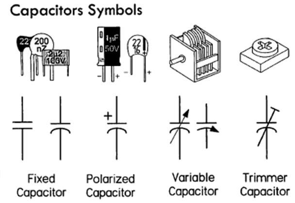
") 1 2 1 Capacitor Capacitor is a passive two-terminal component storing the energy in an electric field charged by the voltage across the dielectric. Fixed Polarized Variable Capacitance is the ratio of
1 2 1 Capacitor Capacitor is a passive two-terminal component storing the energy in an electric field charged by the voltage across the dielectric. Fixed Polarized Variable Capacitance is the ratio of
Radio Frequency Electronics
 Radio Frequency Electronics Preliminaries I Invented Regenerative circuit while an undergraduate (1914) Superheterodyne receiver (1918) Super-regenerative circuit (1922) Frequency modulation (FM) radio
Driven RLC Circuits Challenge Problem Solutions
 Driven LC Circuits Challenge Problem Solutions Problem : Using the same circuit as in problem 6, only this time leaving the function generator on and driving below resonance, which in the following pairs
Sinusoidal Steady State Power Calculations
 10 Sinusoidal Steady State Power Calculations Assessment Problems AP 10.1 [a] V = 100/ 45 V, Therefore I = 20/15 A P = 1 (100)(20)cos[ 45 (15)] = 500W, 2 A B Q = 1000sin 60 = 866.03 VAR, B A [b] V = 100/
Sinusoidal Steady State Analysis
 Sinusoidal Steady State Analysis 9 Assessment Problems AP 9. [a] V = 70/ 40 V [b] 0 sin(000t +20 ) = 0 cos(000t 70 ).. I = 0/ 70 A [c] I =5/36.87 + 0/ 53.3 =4+j3+6 j8 =0 j5 =.8/ 26.57 A [d] sin(20,000πt
6.1 Introduction
 6. Introduction A.C Circuits made up of resistors, inductors and capacitors are said to be resonant circuits when the current drawn from the supply is in phase with the impressed sinusoidal voltage. Then.
Chapter 2 Circuit Elements
 Chapter Circuit Elements Chapter Circuit Elements.... Introduction.... Circuit Element Construction....3 Resistor....4 Inductor...4.5 Capacitor...6.6 Element Basics...8.6. Element Reciprocals...8.6. Reactance...8.6.3
Resonant Matching Networks
 Chapter 1 Resonant Matching Networks 1.1 Introduction Frequently power from a linear source has to be transferred into a load. If the load impedance may be adjusted, the maximum power theorem states that
Handout 11: AC circuit. AC generator
 Handout : AC circuit AC generator Figure compares the voltage across the directcurrent (DC) generator and that across the alternatingcurrent (AC) generator For DC generator, the voltage is constant For
 Capacitors and Inductors Resistor: a passive element which dissipates energy only Two important passive linear circuit elements: 1) Capacitor 2) Inductor Introduction Capacitor and inductor can store energy
EE292: Fundamentals of ECE
 EE292: Fundamentals of ECE Fall 2012 TTh 10:00-11:15 SEB 1242 Lecture 18 121025 http://www.ee.unlv.edu/~b1morris/ee292/ 2 Outline Review RMS Values Complex Numbers Phasors Complex Impedance Circuit Analysis
Prof. Anyes Taffard. Physics 120/220. Voltage Divider Capacitor RC circuits
 Prof. Anyes Taffard Physics 120/220 Voltage Divider Capacitor RC circuits Voltage Divider The figure is called a voltage divider. It s one of the most useful and important circuit elements we will encounter.
Lecture 11 - AC Power
 - AC Power 11/17/2015 Reading: Chapter 11 1 Outline Instantaneous power Complex power Average (real) power Reactive power Apparent power Maximum power transfer Power factor correction 2 Power in AC Circuits
Sinusoidal Steady State Analysis (AC Analysis) Part I
 Part I") Sinusoidal Steady State Analysis (AC Analysis) Part I Amin Electronics and Electrical Communications Engineering Department (EECE) Cairo University elc.n102.eng@gmail.com http://scholar.cu.edu.eg/refky/
Sinusoidal Steady State Analysis (AC Analysis) Part I Amin Electronics and Electrical Communications Engineering Department (EECE) Cairo University elc.n102.eng@gmail.com http://scholar.cu.edu.eg/refky/
Circuit Analysis-II. Circuit Analysis-II Lecture # 5 Monday 23 rd April, 18
 Circuit Analysis-II Capacitors in AC Circuits Introduction ü The instantaneous capacitor current is equal to the capacitance times the instantaneous rate of change of the voltage across the capacitor.
RADIO AMATEUR EXAM GENERAL CLASS
 RAE-Lessons by 4S7VJ 1 CHAPTER- 2 RADIO AMATEUR EXAM GENERAL CLASS By 4S7VJ 2.1 Sine-wave If a magnet rotates near a coil, an alternating e.m.f. (a.c.) generates in the coil. This e.m.f. gradually increase
Unit-2.0 Circuit Element Theory
 Unit2.0 Circuit Element Theory Dr. Anurag Srivastava Associate Professor ABVIIITM, Gwalior Circuit Theory Overview Of Circuit Theory; Lumped Circuit Elements; Topology Of Circuits; Resistors; KCL and KVL;
Electronics. Basics & Applications. group talk Daniel Biesinger
 Electronics Basics & Applications group talk 23.7.2010 by Daniel Biesinger 1 2 Contents Contents Basics Simple applications Equivalent circuit Impedance & Reactance More advanced applications - RC circuits
EE221 Circuits II. Chapter 14 Frequency Response
 EE22 Circuits II Chapter 4 Frequency Response Frequency Response Chapter 4 4. Introduction 4.2 Transfer Function 4.3 Bode Plots 4.4 Series Resonance 4.5 Parallel Resonance 4.6 Passive Filters 4.7 Active
Introduction to AC Circuits (Capacitors and Inductors)
") Introduction to AC Circuits (Capacitors and Inductors) Amin Electronics and Electrical Communications Engineering Department (EECE) Cairo University elc.n102.eng@gmail.com http://scholar.cu.edu.eg/refky/
Introduction to AC Circuits (Capacitors and Inductors) Amin Electronics and Electrical Communications Engineering Department (EECE) Cairo University elc.n102.eng@gmail.com http://scholar.cu.edu.eg/refky/
Inductive & Capacitive Circuits. Subhasish Chandra Assistant Professor Department of Physics Institute of Forensic Science, Nagpur
 Inductive & Capacitive Circuits Subhasish Chandra Assistant Professor Department of Physics Institute of Forensic Science, Nagpur LR Circuit LR Circuit (Charging) Let us consider a circuit having an inductance
1 Phasors and Alternating Currents
 Physics 4 Chapter : Alternating Current 0/5 Phasors and Alternating Currents alternating current: current that varies sinusoidally with time ac source: any device that supplies a sinusoidally varying potential
EE292: Fundamentals of ECE
 EE292: Fundamentals of ECE Fall 2012 TTh 10:00-11:15 SEB 1242 Lecture 20 121101 http://www.ee.unlv.edu/~b1morris/ee292/ 2 Outline Chapters 1-3 Circuit Analysis Techniques Chapter 10 Diodes Ideal Model
Learnabout Electronics - AC Theory
 Learnabout Electronics - AC Theory Facts & Formulae for AC Theory www.learnabout-electronics.org Contents AC Wave Values... 2 Capacitance... 2 Charge on a Capacitor... 2 Total Capacitance... 2 Inductance...
Consider a simple RC circuit. We might like to know how much power is being supplied by the source. We probably need to find the current.
 AC power Consider a simple RC circuit We might like to know how much power is being supplied by the source We probably need to find the current R 10! R 10! is VS Vmcosωt Vm 10 V f 60 Hz V m 10 V C 150
ENGR 2405 Chapter 6. Capacitors And Inductors
 ENGR 2405 Chapter 6 Capacitors And Inductors Overview This chapter will introduce two new linear circuit elements: The capacitor The inductor Unlike resistors, these elements do not dissipate energy They
Physics 1B Spring 2010: Final Version A 1 COMMENTS AND REMINDERS:
 Physics 1B Spring 2010: Final Version A 1 COMMENTS AND REMINDERS: Closed book. No work needs to be shown for multiple-choice questions. 1. Four charges are at the corners of a square, with B and C on opposite
A R E S O N A N T D U M M Y L O A D
 A R E S O N A N T D U M M Y L O A D By Luiz Amaral PY1LL/AC2BR Introduction Our specific problem is to build a dummy load for the 470-510kHz band for a 250W average output power transmitter for that band.
ECE2262 Electric Circuits. Chapter 6: Capacitance and Inductance
 ECE2262 Electric Circuits Chapter 6: Capacitance and Inductance Capacitors Inductors Capacitor and Inductor Combinations Op-Amp Integrator and Op-Amp Differentiator 1 CAPACITANCE AND INDUCTANCE Introduces
Sinusoidal Steady-State Analysis
 Sinusoidal Steady-State Analysis Almost all electrical systems, whether signal or power, operate with alternating currents and voltages. We have seen that when any circuit is disturbed (switched on or
ELECTRO MAGNETIC INDUCTION
 ELECTRO MAGNETIC INDUCTION 1) A Circular coil is placed near a current carrying conductor. The induced current is anti clock wise when the coil is, 1. Stationary 2. Moved away from the conductor 3. Moved
Lecture 24. Impedance of AC Circuits.
 Lecture 4. Impedance of AC Circuits. Don t forget to complete course evaluations: https://sakai.rutgers.edu/portal/site/sirs Post-test. You are required to attend one of the lectures on Thursday, Dec.
Alternating Current Circuits
 Alternating Current Circuits AC Circuit An AC circuit consists of a combination of circuit elements and an AC generator or source. The output of an AC generator is sinusoidal and varies with time according
Note 11: Alternating Current (AC) Circuits
 Circuits") Note 11: Alternating Current (AC) Circuits V R No phase difference between the voltage difference and the current and max For alternating voltage Vmax sin t, the resistor current is ir sin t. the instantaneous
Note 11: Alternating Current (AC) Circuits V R No phase difference between the voltage difference and the current and max For alternating voltage Vmax sin t, the resistor current is ir sin t. the instantaneous
DC and AC Impedance of Reactive Elements
 3/6/20 D and A Impedance of Reactive Elements /6 D and A Impedance of Reactive Elements Now, recall from EES 2 the complex impedances of our basic circuit elements: ZR = R Z = jω ZL = jωl For a D signal
Assessment Schedule 2015 Physics: Demonstrate understanding of electrical systems (91526)
") NCEA Level 3 Physics (91526) 2015 page 1 of 6 Assessment Schedule 2015 Physics: Demonstrate understanding of electrical systems (91526) Evidence Q Evidence Achievement Achievement with Merit Achievement
NCEA Level 3 Physics (91526) 2015 page 1 of 6 Assessment Schedule 2015 Physics: Demonstrate understanding of electrical systems (91526) Evidence Q Evidence Achievement Achievement with Merit Achievement
DATA SHEET SURFACE-MOUNT CERAMIC MULTILAYER CAPACITORS Introduction
 DATA SHEET SURFACE-MOUNT CERAMIC MULTILAYER CAPACITORS Product Specification GENERAL DATA Ceramic capacitors are widely used in electronic circuitry for coupling, decoupling and in filters. These different
Electromagnetic Oscillations and Alternating Current. 1. Electromagnetic oscillations and LC circuit 2. Alternating Current 3.
 Electromagnetic Oscillations and Alternating Current 1. Electromagnetic oscillations and LC circuit 2. Alternating Current 3. RLC circuit in AC 1 RL and RC circuits RL RC Charging Discharging I = emf R
R-L-C Circuits and Resonant Circuits
 P517/617 Lec4, P1 R-L-C Circuits and Resonant Circuits Consider the following RLC series circuit What's R? Simplest way to solve for is to use voltage divider equation in complex notation. X L X C in 0
INTC 1307 Instrumentation Test Equipment Teaching Unit 6 AC Bridges
 IHLAN OLLEGE chool of Engineering & Technology ev. 0 W. lonecker ev. (8/6/0) J. Bradbury INT 307 Instrumentation Test Equipment Teaching Unit 6 A Bridges Unit 6: A Bridges OBJETIVE:. To explain the operation
ECE2262 Electric Circuit
 ECE2262 Electric Circuit Chapter 7: FIRST AND SECOND-ORDER RL AND RC CIRCUITS Response to First-Order RL and RC Circuits Response to Second-Order RL and RC Circuits 1 2 7.1. Introduction 3 4 In dc steady
Chapter 13. Capacitors
 Chapter 13 Capacitors Objectives Describe the basic structure and characteristics of a capacitor Discuss various types of capacitors Analyze series capacitors Analyze parallel capacitors Analyze capacitive
How to measure complex impedance at high frequencies where phase measurement is unreliable.
 Objectives In this course you will learn the following Various applications of transmission lines. How to measure complex impedance at high frequencies where phase measurement is unreliable. How and why
Capacitors. Charging a Capacitor. Charge and Capacitance. L05: Capacitors and Inductors
 L05: Capacitors and Inductors 50 Capacitors 51 Outline of the lecture: Capacitors and capacitance. Energy storage. Capacitance formula. Types of capacitors. Inductors and inductance. Inductance formula.
CHAPTER 22 ELECTROMAGNETIC INDUCTION
 CHAPTER 22 ELECTROMAGNETIC INDUCTION PROBLEMS 47. REASONING AND Using Equation 22.7, we find emf 2 M I or M ( emf 2 ) t ( 0.2 V) ( 0.4 s) t I (.6 A) ( 3.4 A) 9.3 0 3 H 49. SSM REASONING AND From the results
AC Circuits. The Capacitor
 The Capacitor Two conductors in close proximity (and electrically isolated from one another) form a capacitor. An electric field is produced by charge differences between the conductors. The capacitance
Multilayer Ceramic Capacitors Leaded Capacitors. Packaging. Internal coding. Capacitance tolerance
 Leaded Capacitors Leaded Ordering code system B37979N 1 100 K 0 54 Packaging 51 ^ cardboard tape, reel packing (360-mm reel) 54 ^ Ammo packing (standard) 00 ^ bulk Internal coding Capacitance tolerance
EXPERIMENT 07 TO STUDY DC RC CIRCUIT AND TRANSIENT PHENOMENA
 EXPERIMENT 07 TO STUDY DC RC CIRCUIT AND TRANSIENT PHENOMENA DISCUSSION The capacitor is a element which stores electric energy by charging the charge on it. Bear in mind that the charge on a capacitor
Electric Circuit Theory
 Electric Circuit Theory Nam Ki Min nkmin@korea.ac.kr 010-9419-2320 Chapter 11 Sinusoidal Steady-State Analysis Nam Ki Min nkmin@korea.ac.kr 010-9419-2320 Contents and Objectives 3 Chapter Contents 11.1
Some Important Electrical Units
 Some Important Electrical Units Quantity Unit Symbol Current Charge Voltage Resistance Power Ampere Coulomb Volt Ohm Watt A C V W W These derived units are based on fundamental units from the meterkilogram-second
Part 4: Electromagnetism. 4.1: Induction. A. Faraday's Law. The magnetic flux through a loop of wire is
 1 Part 4: Electromagnetism 4.1: Induction A. Faraday's Law The magnetic flux through a loop of wire is Φ = BA cos θ B A B = magnetic field penetrating loop [T] A = area of loop [m 2 ] = angle between field
EE221 Circuits II. Chapter 14 Frequency Response
 EE22 Circuits II Chapter 4 Frequency Response Frequency Response Chapter 4 4. Introduction 4.2 Transfer Function 4.3 Bode Plots 4.4 Series Resonance 4.5 Parallel Resonance 4.6 Passive Filters 4.7 Active
Lecture 4: R-L-C Circuits and Resonant Circuits
 Lecture 4: R-L-C Circuits and Resonant Circuits RLC series circuit: What's V R? Simplest way to solve for V is to use voltage divider equation in complex notation: V X L X C V R = in R R + X C + X L L
Announcements: Today: more AC circuits
 Announcements: Today: more AC circuits I 0 I rms Current through a light bulb I 0 I rms I t = I 0 cos ωt I 0 Current through a LED I t = I 0 cos ωt Θ(cos ωt ) Theta function (is zero for a negative argument)
Alternating Current (AC) Circuits
 Circuits") Alternating Current (AC) Circuits We have been talking about DC circuits Constant currents and voltages Resistors Linear equations Now we introduce AC circuits Time-varying currents and voltages Resistors,
Alternating Current (AC) Circuits We have been talking about DC circuits Constant currents and voltages Resistors Linear equations Now we introduce AC circuits Time-varying currents and voltages Resistors,
AC Circuits Homework Set
 Problem 1. In an oscillating LC circuit in which C=4.0 μf, the maximum potential difference across the capacitor during the oscillations is 1.50 V and the maximum current through the inductor is 50.0 ma.
EE 40: Introduction to Microelectronic Circuits Spring 2008: Midterm 2
 EE 4: Introduction to Microelectronic Circuits Spring 8: Midterm Venkat Anantharam 3/9/8 Total Time Allotted : min Total Points:. This is a closed book exam. However, you are allowed to bring two pages
Chapter 6 Objectives
 hapter 6 Engr8 ircuit Analysis Dr urtis Nelson hapter 6 Objectives Understand relationships between voltage, current, power, and energy in inductors and capacitors; Know that current must be continuous
12. Introduction and Chapter Objectives
 Real Analog - Circuits 1 Chapter 1: Steady-State Sinusoidal Power 1. Introduction and Chapter Objectives In this chapter we will address the issue of power transmission via sinusoidal or AC) signals. This
Chapt ha e pt r e r 9 Capacitors
 Chapter 9 Capacitors Basics of a Capacitor In its simplest form, a capacitor is an electrical device constructed of two parallel plates separated by an insulating material called the dielectric In the
Sinusoidal Response of RLC Circuits
 Sinusoidal Response of RLC Circuits Series RL circuit Series RC circuit Series RLC circuit Parallel RL circuit Parallel RC circuit R-L Series Circuit R-L Series Circuit R-L Series Circuit Instantaneous
Chapter 21: RLC Circuits. PHY2054: Chapter 21 1
 Chapter 21: RC Circuits PHY2054: Chapter 21 1 Voltage and Current in RC Circuits AC emf source: driving frequency f ε = ε sinωt ω = 2π f m If circuit contains only R + emf source, current is simple ε ε
Characteristic of Capacitors
 3.5. The Effect of Non ideal Capacitors Characteristic of Capacitors 12 0 (db) 10 20 30 capacitor 0.001µF (1000pF) Chip monolithic 40 two-terminal ceramic capacitor 0.001µF (1000pF) 2.0 x 1.25 x 0.6 mm
Oscillations and Electromagnetic Waves. March 30, 2014 Chapter 31 1
 Oscillations and Electromagnetic Waves March 30, 2014 Chapter 31 1 Three Polarizers! Consider the case of unpolarized light with intensity I 0 incident on three polarizers! The first polarizer has a polarizing
Physics 4B Chapter 31: Electromagnetic Oscillations and Alternating Current
 Physics 4B Chapter 31: Electromagnetic Oscillations and Alternating Current People of mediocre ability sometimes achieve outstanding success because they don't know when to quit. Most men succeed because
Lecture 9 Time Domain vs. Frequency Domain
 . Topics covered Lecture 9 Time Domain vs. Frequency Domain (a) AC power in the time domain (b) AC power in the frequency domain (c) Reactive power (d) Maximum power transfer in AC circuits (e) Frequency
Transmission Lines in the Frequency Domain
 Berkeley Transmission Lines in the Frequency Domain Prof. Ali M. Niknejad U.C. Berkeley Copyright c 2016 by Ali M. Niknejad August 30, 2017 1 / 38 Why Sinusoidal Steady-State? 2 / 38 Time Harmonic Steady-State
 Alternating Currents. The power is transmitted from a power house on high voltage ac because (a) Electric current travels faster at higher volts (b) It is more economical due to less power wastage (c)
Lecture 05 Power in AC circuit
 CA2627 Building Science Lecture 05 Power in AC circuit Instructor: Jiayu Chen Ph.D. Announcement 1. Makeup Midterm 2. Midterm grade Grade 25 20 15 10 5 0 10 15 20 25 30 35 40 Grade Jiayu Chen, Ph.D. 2
SINUSOIDAL STEADY STATE CIRCUIT ANALYSIS
 SINUSOIDAL STEADY STATE CIRCUIT ANALYSIS 1. Introduction A sinusoidal current has the following form: where I m is the amplitude value; ω=2 πf is the angular frequency; φ is the phase shift. i (t )=I m.sin
Impedance and Loudspeaker Parameter Measurement
 ECEN 2260 Circuits/Electronics 2 Spring 2007 2-26-07 P. Mathys Impedance and Loudspeaker Parameter Measurement 1 Impedance Measurement Many elements from which electrical circuits are built are two-terminal
Chapter 5 Steady-State Sinusoidal Analysis
 Chapter 5 Steady-State Sinusoidal Analysis Chapter 5 Steady-State Sinusoidal Analysis 1. Identify the frequency, angular frequency, peak value, rms value, and phase of a sinusoidal signal. 2. Solve steady-state
Inductors. Hydraulic analogy Duality with capacitor Charging and discharging. Lecture 12: Inductors
 Lecture 12: nductors nductors Hydraulic analogy Duality with capacitor Charging and discharging Robert R. McLeod, University of Colorado http://hilaroad.com/camp/projects/magnet.html 99 Lecture 12: nductors
SCHOOL OF MATHEMATICS MATHEMATICS FOR PART I ENGINEERING. Self-paced Course
 SCHOOL OF MATHEMATICS MATHEMATICS FOR PART I ENGINEERING Self-paced Course MODULE 26 APPLICATIONS TO ELECTRICAL CIRCUITS Module Topics 1. Complex numbers and alternating currents 2. Complex impedance 3.
CIRCUIT ANALYSIS II. (AC Circuits)
") Will Moore MT & MT CIRCUIT ANALYSIS II (AC Circuits) Syllabus Complex impedance, power factor, frequency response of AC networks including Bode diagrams, second-order and resonant circuits, damping and
Will Moore MT & MT CIRCUIT ANALYSIS II (AC Circuits) Syllabus Complex impedance, power factor, frequency response of AC networks including Bode diagrams, second-order and resonant circuits, damping and
Physics 2B Spring 2010: Final Version A 1 COMMENTS AND REMINDERS:
 Physics 2B Spring 2010: Final Version A 1 COMMENTS AND REMINDERS: Closed book. No work needs to be shown for multiple-choice questions. 1. A charge of +4.0 C is placed at the origin. A charge of 3.0 C
The Farad is a very big unit so the following subdivisions are used in
 Passages in small print are for interest and need not be learnt for the R.A.E. Capacitance Consider two metal plates that are connected to a battery. The battery removes a few electrons from plate "A"
Physics 240 Fall 2005: Exam #3 Solutions. Please print your name: Please list your discussion section number: Please list your discussion instructor:
 Physics 4 Fall 5: Exam #3 Solutions Please print your name: Please list your discussion section number: Please list your discussion instructor: Form #1 Instructions 1. Fill in your name above. This will
f = 1 T 6 a.c. (Alternating Current) Circuits Most signals of interest in electronics are periodic : they repeat regularly as a function of time.
 Circuits Most signals of interest in electronics are periodic : they repeat regularly as a function of time.") Analogue Electronics (Aero).66 66 Analogue Electronics (Aero) 6.66 6 a.c. (Alternating Current) Circuits Most signals of interest in electronics are periodic : they repeat regularly as a function of time.
Analogue Electronics (Aero).66 66 Analogue Electronics (Aero) 6.66 6 a.c. (Alternating Current) Circuits Most signals of interest in electronics are periodic : they repeat regularly as a function of time.
P A R T 2 AC CIRCUITS. Chapter 9 Sinusoids and Phasors. Chapter 10 Sinusoidal Steady-State Analysis. Chapter 11 AC Power Analysis
 P A R T 2 AC CIRCUITS Chapter 9 Sinusoids and Phasors Chapter 10 Sinusoidal Steady-State Analysis Chapter 11 AC Power Analysis Chapter 12 Three-Phase Circuits Chapter 13 Magnetically Coupled Circuits Chapter
AC Circuits III. Physics 2415 Lecture 24. Michael Fowler, UVa
 AC Circuits III Physics 415 Lecture 4 Michael Fowler, UVa Today s Topics LC circuits: analogy with mass on spring LCR circuits: damped oscillations LCR circuits with ac source: driven pendulum, resonance.
Impedance/Reactance Problems
 Impedance/Reactance Problems. Consider the circuit below. An AC sinusoidal voltage of amplitude V and frequency ω is applied to the three capacitors, each of the same capacitance C. What is the total reactance
EXP. NO. 3 Power on (resistive inductive & capacitive) load Series connection
 load Series connection") OBJECT: To examine the power distribution on (R, L, C) series circuit. APPARATUS 1-signal function generator 2- Oscilloscope, A.V.O meter 3- Resisters & inductor &capacitor THEORY the following form for
OBJECT: To examine the power distribution on (R, L, C) series circuit. APPARATUS 1-signal function generator 2- Oscilloscope, A.V.O meter 3- Resisters & inductor &capacitor THEORY the following form for
TE Connectivity Capacitive Products
 TE Connectivity Capacitive Products SM MLCC Capacitors - Product Overview The TYC Range Multilayer Ceramic (MLCC) capacitors are available in NPO(COG), X7R, X5R or Y5V(Z5U) dielectrics. Available in a
RLC Series Circuit. We can define effective resistances for capacitors and inductors: 1 = Capacitive reactance:
 RLC Series Circuit In this exercise you will investigate the effects of changing inductance, capacitance, resistance, and frequency on an RLC series AC circuit. We can define effective resistances for
CIRCUIT ELEMENT: CAPACITOR
 CIRCUIT ELEMENT: CAPACITOR PROF. SIRIPONG POTISUK ELEC 308 Types of Circuit Elements Two broad types of circuit elements Ati Active elements -capable of generating electric energy from nonelectric energy
Alternating Current Circuits. Home Work Solutions
 Chapter 21 Alternating Current Circuits. Home Work s 21.1 Problem 21.11 What is the time constant of the circuit in Figure (21.19). 10 Ω 10 Ω 5.0 Ω 2.0µF 2.0µF 2.0µF 3.0µF Figure 21.19: Given: The circuit
MODULE-4 RESONANCE CIRCUITS
 Introduction: MODULE-4 RESONANCE CIRCUITS Resonance is a condition in an RLC circuit in which the capacitive and inductive Reactance s are equal in magnitude, there by resulting in purely resistive impedance.
Yell if you have any questions
 Class 31: Outline Hour 1: Concept Review / Overview PRS Questions possible exam questions Hour : Sample Exam Yell if you have any questions P31 1 Exam 3 Topics Faraday s Law Self Inductance Energy Stored
Alternating Current. Symbol for A.C. source. A.C.
 Alternating Current Kirchoff s rules for loops and junctions may be used to analyze complicated circuits such as the one below, powered by an alternating current (A.C.) source. But the analysis can quickly
15-884/484 Electric Power Systems 1: DC and AC Circuits
 15-884/484 Electric Power Systems 1: DC and AC Circuits J. Zico Kolter October 8, 2013 1 Hydro Estimated U.S. Energy Use in 2010: ~98.0 Quads Lawrence Livermore National Laboratory Solar 0.11 0.01 8.44
mywbut.com Lesson 16 Solution of Current in AC Parallel and Seriesparallel
 esson 6 Solution of urrent in Parallel and Seriesparallel ircuits n the last lesson, the following points were described:. How to compute the total impedance/admittance in series/parallel circuits?. How