TCS SERVO SYSTEM: Mechanical Modeling
|
|
|
- Verity Thomas
- 5 years ago
- Views:
Transcription
1 UNIVERSITY OF HAWAII INSTITUTE FOR ASTRONOMY 2680 Woodlawn Dr. Honolulu, HI NASA Infrared Telescope Facility TCS SERVO SYSTEM: Mechanical Modeling Tim Bond May 12 / 2004 Version 1.0
2 Overview: The following is a document describing the work performed with respect to mechanical issues, for the TCS servo design. Early in the development of the new IRTF telescope control system (TCS) it was determined that we needed to fully define the servo system in order to understand its impact on overall system specifications. How the servo loop effected the specifications would also determine how other contributions to the image degradation (such as wind disturbances, encoder resolutions, nonlinearities.) would be handled. We decided that we needed to construct a simplified analytical mechanical model of the telescope, and to this model, we would apply our new TCS system in order to determine the final performance. A mathematical model was first constructed, and the governing differential equations were processed for a solution. In the end, the equations became unwieldy and it was decided that we would need to implement a computer mathematical package (Matlab) in order to solve the equations. After starting work in the package, we discovered that there were built in blocks and subroutines that could greatly simplify the modeling process for us. In the end, we simply modeled the entire system in Matlab Simulink. The first step in the process was to reverse engineer a JPL document that was produced in the preliminary stages of the IRTF development (mid 1970 s). The information used in that document was then used to construct a model of the IRTF in its current state with its current analogue control system. Once we were happy with this model, we stripped the analogue control system away, and then began to implement the new digital control system. Our final model was lacking in any type of external disturbances, and so an effort was undertaken to add wind loading to the structure. It was felt that this would be the most significant external disturbance to the system, and a good test of the controls systems disturbance rejection. 2
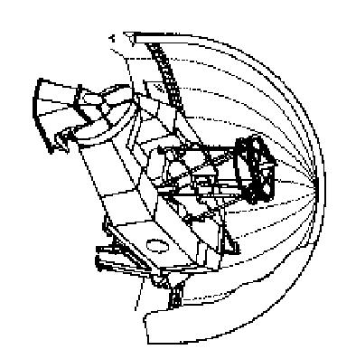
3 JPL Model (5 DOF): Background: See JPL Interoffice Memo : Dynamic Analysis of the 3M Mauna Kea Telescope, and Interoffice Memo : Preliminary Input Parameters for Servo Analysis Model. The JPL documents mentioned above, were extremely thorough in their development of an analytical model; however, there were several things that we felt we could / should improve upon. Firstly, the analytical model incorporated both the mechanical system as well as the control system into one single model. We needed to split the two systems apart in order that we would be able to replace the control portion in the future with our new digital system. The resulting mechanical portion of the model is the subject of this document. Secondly, we felt that we needed to add an extra degree of freedom to account for the fact that there were two drive motors on the IRTF, each with its own tachometer. The JPL model contained only a single motor with a single tachometer. We felt that this was a significant difference, and that we needed to model the two motor system in order to correctly determine the subtleties of the velocity loop (which ends up being the heart of the disturbance rejection system). Lastly we decided to add some random noise to the system in the form of wind loading. We felt that it was important to try to add some form of disturbance to the system in order to exercise the velocity loops of the servo. The 5 DOF Mechanical Model: A lumped mass model of the telescope was constructed with the following degrees of freedom: 1) Telescope foundation. 2) South pier, including the motor stator and gear case. 3) Motor rotor and drive gears. 4) Telescope yoke, tube, and bull gear. 5) North pier. 3
4 Attached drawing # shows the model in Fig. #1, with all of the variables defined. The 5 governing equations for the five degrees of freedom were derived and listed below the model. It should be noted that all of the degrees of freedom are rotational. In the model, the k ij s are associated with stiffness (or rotational spring coefficients) between the elements, the J i s are the mass moment of inertia of the rotational elements, the b ij s are the damping coefficients between the elements, and the Ø i s are the angular position of the element. The values used for these coefficients are taken from the JPL derivation and are listed as follows: b 01 = x 10 6 N m s J 1 = x 10 3 kg m 2 b 12 = x 10 6 N m s J 2 = 7897 kg m 2 b 23 = x 10 6 N m s J 3 = kg m 2 b 34 = x 10 6 N m s J 4 = kg m 2 b 45 = x 10 6 N m s J 5 = kg m 2 b 51 = x 10 6 N m s k 01 = 4561 x 10 6 N m k 12 = 8993 x 10 6 N m k 34 = 587 x 10 6 N m k 51 = 955 x 10 6 N m kk 1 = x 10-3 N m/volt m =.6044 x 10 6 N m s Details of how these coefficients are derived are given in the JPL documents. The 5 DOF MATLAB Model: From the differential equations, the Matlab model was created. The actual model is shown in the attached drawing # The model takes as an input, a single torque (in N m) and gives an output of position (in rad) of the telescope tube, and velocity (in rad/s) of drive motors. These are actually given relative to the south pier (J 2 ), just as the actual encoders on the telescope would produce. Model Verification: From the model, we are able to run simulations and determine where the locked rotor resonant frequencies were. It would be extremely useful if time permitted in the future, to attempt to determine the first few (lowest) natural frequencies on the actual telescope. This would be one method for confirming the assumed spring constants, and mass moments of inertia from the JPL document. 4
5 IRTF Model (6 DOF): Background: As was mentioned previously, we felt that one of the most important things for us to model was the disturbance rejection of the system, or more precisely - the effectiveness of the velocity loops. The model developed by the JPL staff contained only one motor with a single tachometer on it. The actual IRTF has two motors back-driving against each other, with an individual tachometer on each motor. We decided that we needed to add this second motor (and tachometer) to our model if we were really serious about using the model to simulate our telescope. The 6 DOF Mechanical Model: Again, a lumped mass model of the telescope was constructed, this time with the following degrees of freedom: 1) Telescope foundation. 2) South pier, including the motor stator and gear case. 3) A - motor rotor and drive gears. 4) B - motor rotor and drive gears. 5) Telescope yoke, tube, and bull gear. 6) North pier. Attached drawing # shows the model in Fig. #1, with all of the variables again defined. The 6 governing equations for the 6 degrees of freedom are derived from the model and listed below it. In the JPL 5 DOF model, the stiffness and damping constants, associated with the motor rotor and gears, were determined experimentally from a test at KPNO (see JPL documentation). These values were added into the model, and simply applied in a negative sense if the motor was driving in a negative direction (this assumes zero backlash). What this means is that we can use the exact same values in our 6 DOF model, as each motors will only apply a moment in a single direction (opposing each other to remove the backlash). The model is shown in terms of its spring and damping coefficients, and its mass moments of inertia. Once again, the values used for these coefficients are taken from the JPL derivation and are listed as follows: 5
6 b 01 = x 10 6 N m s J 1 = x 10 3 kg m 2 b 12 = x 10 6 N m s J 2 = 7897 kg m 2 b 23 = x 10 6 N m s J 3a = kg m 2 b 34 = x 10 6 N m s J 3b = kg m 2 b 45 = x 10 6 N m s J 4 = kg m 2 b 51 = x 10 6 N m s J 5 = kg m 2 k 01 = 4561 x 10 6 N m k 12 = 8993 x 10 6 N m k 34 = 587 x 10 6 N m k 51 = 955 x 10 6 N m kk 1 = x 10-3 N m/volt m =.6044 x 10 6 N m s Again, details of how these coefficients are derived are given in the JPL documents. The 6 DOF MATLAB Model: From the differential equations, the Matlab model was created. The actual model is shown in the attached drawing # The model takes as inputs, two torques (in N m) and gives as outputs, position (in rad) of the telescope tube, and the two velocities (in rad/s) of the two drive motors. These are actually given relative to the south pier (J 2 ), just as the actual encoders on the telescope would produce. Model Verification: Again, from the model, we are able to run simulations and determine where the locked rotor resonant frequencies were. It would be extremely useful if time permitted in the future, to attempt to determine the first few (lowest) natural frequencies on the actual telescope. This would be one method for confirming the assumed spring constants, and mass moments of inertia from the JPL document. 6
7 Disturbance Rejection: Wind Loading Background: Early in the TCS project, there were questions as to whether a velocity loop was really required in the servo design. Most of the literature studied, seemed to suggest that the velocity loop was imperative in order to meet the disturbance rejection requirements. We felt that in order to fully comprehend the importance of the velocity loops, we should try to add some form of disturbance to our model. In reality, one of the most significant of these disturbances is wind loading, and so we decided to add some form of wind loading to our model. It should be noted that the wind loading model used in the following calculations is by no means the most correct model. It is just a simple approximation as to what we might see at the telescope, and is really just used as a ball park approximation of a disturbance for testing our servo system s disturbance rejection ability. The weaknesses in our model will be pointed out as we develop it in the following sections. Steady State Loading: A calculation was performed to determine the steady state loading on the top end of the telescope structure, due to a wind force. Our calculation is based on empirical data and is common in any standard fluid dynamics textbook. Details of the calculation are given in drawing # and # All of the assumptions made are noted in the drawings, and the final result may be summarized as: The approximate torque applied to the telescope axis due to drag induced by a 10mph wind on the top end structure is determined to be N m. The largest assumption made in this approximation is that the top end would be exposed to a free air velocity of 10mph. This is analogous to assuming that the telescope is sitting in a large open field, exposed to the 10mph wind. In reality, our telescope is located inside our dome, and is somewhat sheltered from a much larger (typically 30mph) wind speed outside of the dome. 7

8 Wind Power Spectral Density: In reality, the wind forces that the telescope will be exposed to will be time varying and somewhat erratic. This is a result of the turbulent flow inside the dome as well as the result of vortex shedding off of the structure itself. Much of the literature found on the subject of wind loading showed PSD curves that rolled off at higher frequencies. As a result we attempted to construct a model based on a band limited white noise generator. Theoretically, the PSD curve of this signal is a constant and so we simply processed the signal with a Butterworth Low-Pass filter with the desired cutoff frequency. The signal was then given the appropriate gain factor in order to produce an RMS value identical to the steady state value determined above. The MATLAB Wind Simulation Model: The Matlab model used for the wind simulation is shown in drawing # and the scope results are shown below: The top trace is the signal passed through a 5 rad/s roll-off filter and the plot immediately below it is of the cumulative RMS value. The third trace is the signal passed through a 2 rad/s roll-off filter and the plot immediately below it is of the cumulative RMS value. 8
9 The fifth trace is the signal passed through a 0.2 rad/s roll-off filter and the plot immediately below it is of the cumulative RMS value. As can be seen, the peak to valley of the signal is approximately 3 times the RMS value, as would be expected for a normally distributed random variable. The assumption that we have made is that at the telescope, the 10mph value that we used for steady state loading is actually the RMS of what we would measure inside the dome. This may be somewhat conservative, and result in loads that are actually larger than we would see in reality. The end result is that the signal that is sent to the telescope tube in our telescope model is the signal selected above, normalized to give a RMS value of 500 N m (as shown by the final gain block in the model). The three different values selected for roll-off were chosen arbitrarily. In reality, the 5 rad/s roll-off signal would be more difficult for the servo to correct, but the 0.2 rad/s signal seemed to be a more appropriate signal to use intuitively. The model was left with all three signals in it so that the user could select which one he felt was appropriate. 9
10
11
12

13
14
15
16
Mechatronics Modeling and Analysis of Dynamic Systems Case-Study Exercise
 Mechatronics Modeling and Analysis of Dynamic Systems Case-Study Exercise Goal: This exercise is designed to take a real-world problem and apply the modeling and analysis concepts discussed in class. As
Manufacturing Equipment Control
 QUESTION 1 An electric drive spindle has the following parameters: J m = 2 1 3 kg m 2, R a = 8 Ω, K t =.5 N m/a, K v =.5 V/(rad/s), K a = 2, J s = 4 1 2 kg m 2, and K s =.3. Ignore electrical dynamics
Mechatronics Engineering. Li Wen
 Mechatronics Engineering Li Wen Bio-inspired robot-dc motor drive Unstable system Mirko Kovac,EPFL Modeling and simulation of the control system Problems 1. Why we establish mathematical model of the control
Modelling and simulation of a measurement robot
 Modellbygge och Simulering, TSRT62 Modelling and simulation of a measurement robot Denna version: 4 oktober 2017 Servo- motor Strömregulator + u + i(t) [A] r (t) [V] u(t) [V] Arm Skruvtransmission Remtransmission
Laboratory 11 Control Systems Laboratory ECE3557. State Feedback Controller for Position Control of a Flexible Joint
 Laboratory 11 State Feedback Controller for Position Control of a Flexible Joint 11.1 Objective The objective of this laboratory is to design a full state feedback controller for endpoint position control
SRV02-Series Rotary Experiment # 1. Position Control. Student Handout
 SRV02-Series Rotary Experiment # 1 Position Control Student Handout SRV02-Series Rotary Experiment # 1 Position Control Student Handout 1. Objectives The objective in this experiment is to introduce the
MASS LOADING EFFECTS FOR HEAVY EQUIPMENT AND PAYLOADS Revision F
 MASS LOADING EFFECTS FOR HEAVY EQUIPMENT AND PAYLOADS Revision F By Tom Irvine Email: tomirvine@aol.com May 19, 2011 Introduction Consider a launch vehicle with a payload. Intuitively, a realistic payload
MODELING AND HIGH-PERFORMANCE CONTROL OF ELECTRIC MACHINES
 MODELING AND HIGH-PERFORMANCE CONTROL OF ELECTRIC MACHINES JOHN CHIASSON IEEE PRESS ü t SERIES ON POWER ENGINEERING IEEE Press Series on Power Engineering Mohamed E. El-Hawary, Series Editor The Institute
ROBUST CONTROL OF A FLEXIBLE MANIPULATOR ARM: A BENCHMARK PROBLEM. Stig Moberg Jonas Öhr
 ROBUST CONTROL OF A FLEXIBLE MANIPULATOR ARM: A BENCHMARK PROBLEM Stig Moberg Jonas Öhr ABB Automation Technologies AB - Robotics, S-721 68 Västerås, Sweden stig.moberg@se.abb.com ABB AB - Corporate Research,
( ) Chapter 3: Free Vibration of the Breakwater. 3.1 Introduction
 Chapter 3: Free Vibration of the Breakwater. 3.1 Introduction") Chapter : Free Vibration of the Breakwater. Introduction Before conducting forcing analyses on the breakwater, a free vibration study is necessary. This chapter will describe the analysis conducted to
Chapter : Free Vibration of the Breakwater. Introduction Before conducting forcing analyses on the breakwater, a free vibration study is necessary. This chapter will describe the analysis conducted to
Overview of motors and motion control
 Overview of motors and motion control. Elements of a motion-control system Power upply High-level controller ow-level controller Driver Motor. Types of motors discussed here; Brushed, PM DC Motors Cheap,
2.004 Dynamics and Control II Spring 2008
 MIT OpenCourseWare http://ocw.mit.edu 2.004 Dynamics and Control II Spring 2008 For information about citing these materials or our Terms of Use, visit: http://ocw.mit.edu/terms. Massachusetts Institute
Introduction to Control (034040) lecture no. 2
 lecture no. 2") Introduction to Control (034040) lecture no. 2 Leonid Mirkin Faculty of Mechanical Engineering Technion IIT Setup: Abstract control problem to begin with y P(s) u where P is a plant u is a control signal
Introduction to Control (034040) lecture no. 2 Leonid Mirkin Faculty of Mechanical Engineering Technion IIT Setup: Abstract control problem to begin with y P(s) u where P is a plant u is a control signal
AN EXPERIMENTAL WEB TENSION CONTROL SYSTEM: SYSTEM SET-UP
 Advances in Production Engineering & Management 2 (2007) 4, 185-193 ISSN 1854-6250 Professional paper AN EXPERIMENTAL WEB TENSION CONTROL SYSTEM: SYSTEM SET-UP Giannoccaro, N.I. * ; Oishi, K. ** & Sakamoto,
a) Find the equation of motion of the system and write it in matrix form.
 Find the equation of motion of the system and write it in matrix form.") .003 Engineering Dynamics Problem Set Problem : Torsional Oscillator Two disks of radius r and r and mass m and m are mounted in series with steel shafts. The shaft between the base and m has length L
.003 Engineering Dynamics Problem Set Problem : Torsional Oscillator Two disks of radius r and r and mass m and m are mounted in series with steel shafts. The shaft between the base and m has length L
Exercise 5 - Hydraulic Turbines and Electromagnetic Systems
 Exercise 5 - Hydraulic Turbines and Electromagnetic Systems 5.1 Hydraulic Turbines Whole courses are dedicated to the analysis of gas turbines. For the aim of modeling hydraulic systems, we analyze here
Some tools and methods for determination of dynamics of hydraulic systems
 Some tools and methods for determination of dynamics of hydraulic systems A warm welcome to the course in Hydraulic servo-techniques! The purpose of the exercises given in this material is to make you
SRV02-Series Rotary Experiment # 7. Rotary Inverted Pendulum. Student Handout
 SRV02-Series Rotary Experiment # 7 Rotary Inverted Pendulum Student Handout SRV02-Series Rotary Experiment # 7 Rotary Inverted Pendulum Student Handout 1. Objectives The objective in this experiment is
Dynamics of the Otto Struve [2.1-Meter] Telescope
![Dynamics of the Otto Struve [2.1-Meter] Telescope](/thumbs/77/76406415.jpg "Dynamics of the Otto Struve [2.1-Meter] Telescope") Dynamics of the Otto Struve [2.1-Meter] Telescope Davis Varghese August 15, 2009 1.0 INTRODUCTION 1.1 Purpose of Research Project The Otto Struve [2.1-Meter] Telescope at McDonald Observatory collected
Dynamics of the Otto Struve [2.1-Meter] Telescope Davis Varghese August 15, 2009 1.0 INTRODUCTION 1.1 Purpose of Research Project The Otto Struve [2.1-Meter] Telescope at McDonald Observatory collected
Automatic Control Systems. -Lecture Note 15-
 -Lecture Note 15- Modeling of Physical Systems 5 1/52 AC Motors AC Motors Classification i) Induction Motor (Asynchronous Motor) ii) Synchronous Motor 2/52 Advantages of AC Motors i) Cost-effective ii)
Coupled Drive Apparatus Modelling and Simulation
 University of Ljubljana Faculty of Electrical Engineering Victor Centellas Gil Coupled Drive Apparatus Modelling and Simulation Diploma thesis Menthor: prof. dr. Maja Atanasijević-Kunc Ljubljana, 2015
FEEDBACK CONTROL SYSTEMS
 FEEDBAC CONTROL SYSTEMS. Control System Design. Open and Closed-Loop Control Systems 3. Why Closed-Loop Control? 4. Case Study --- Speed Control of a DC Motor 5. Steady-State Errors in Unity Feedback Control
MECH 3140 Final Project
 MECH 3140 Final Project Final presentation will be held December 7-8. The presentation will be the only deliverable for the final project and should be approximately 20-25 minutes with an additional 10
Positioning Servo Design Example
 Positioning Servo Design Example 1 Goal. The goal in this design example is to design a control system that will be used in a pick-and-place robot to move the link of a robot between two positions. Usually
Laboratory Exercise 1 DC servo
 Laboratory Exercise DC servo Per-Olof Källén ø 0,8 POWER SAT. OVL.RESET POS.RESET Moment Reference ø 0,5 ø 0,5 ø 0,5 ø 0,65 ø 0,65 Int ø 0,8 ø 0,8 Σ k Js + d ø 0,8 s ø 0 8 Off Off ø 0,8 Ext. Int. + x0,
Final Exam April 30, 2013
 Final Exam Instructions: You have 120 minutes to complete this exam. This is a closed-book, closed-notes exam. You are allowed to use a calculator during the exam. Usage of mobile phones and other electronic
The basic principle to be used in mechanical systems to derive a mathematical model is Newton s law,
 Chapter. DYNAMIC MODELING Understanding the nature of the process to be controlled is a central issue for a control engineer. Thus the engineer must construct a model of the process with whatever information
THE REACTION WHEEL PENDULUM
 THE REACTION WHEEL PENDULUM By Ana Navarro Yu-Han Sun Final Report for ECE 486, Control Systems, Fall 2013 TA: Dan Soberal 16 December 2013 Thursday 3-6pm Contents 1. Introduction... 1 1.1 Sensors (Encoders)...
Lexium integrated drives
 Presentation GBX planetary gearbox Presentation In many cases the axis controller requires the use of a planetary gearbox for adjustment of speed of rotation and torque; the accuracy required by the application
Rotary Motion Servo Plant: SRV02. Rotary Experiment #01: Modeling. SRV02 Modeling using QuaRC. Student Manual
 Rotary Motion Servo Plant: SRV02 Rotary Experiment #01: Modeling SRV02 Modeling using QuaRC Student Manual SRV02 Modeling Laboratory Student Manual Table of Contents 1. INTRODUCTION...1 2. PREREQUISITES...1
Quanser NI-ELVIS Trainer (QNET) Series: QNET Experiment #02: DC Motor Position Control. DC Motor Control Trainer (DCMCT) Student Manual
 Series: QNET Experiment #02: DC Motor Position Control. DC Motor Control Trainer (DCMCT) Student Manual") Quanser NI-ELVIS Trainer (QNET) Series: QNET Experiment #02: DC Motor Position Control DC Motor Control Trainer (DCMCT) Student Manual Table of Contents 1 Laboratory Objectives1 2 References1 3 DCMCT Plant
Quanser NI-ELVIS Trainer (QNET) Series: QNET Experiment #02: DC Motor Position Control DC Motor Control Trainer (DCMCT) Student Manual Table of Contents 1 Laboratory Objectives1 2 References1 3 DCMCT Plant
ME 3210 Mechatronics II Laboratory Lab 4: DC Motor Characteristics
 ME 3210 Mechatronics II Laboratory Lab 4: DC Motor Characteristics Introduction Often, due to budget constraints or convenience, engineers must use whatever tools are available to create new or improved
Lab 3: Model based Position Control of a Cart
 I. Objective Lab 3: Model based Position Control of a Cart The goal of this lab is to help understand the methodology to design a controller using the given plant dynamics. Specifically, we would do position
ROLLER BEARING FAILURES IN REDUCTION GEAR CAUSED BY INADEQUATE DAMPING BY ELASTIC COUPLINGS FOR LOW ORDER EXCITATIONS
 ROLLER BEARIG FAILURES I REDUCTIO GEAR CAUSED BY IADEQUATE DAMPIG BY ELASTIC COUPLIGS FOR LOW ORDER EXCITATIOS ~by Herbert Roeser, Trans Marine Propulsion Systems, Inc. Seattle Flexible couplings provide
DOUBLE ARM JUGGLING SYSTEM Progress Presentation ECSE-4962 Control Systems Design
 DOUBLE ARM JUGGLING SYSTEM Progress Presentation ECSE-4962 Control Systems Design Group Members: John Kua Trinell Ball Linda Rivera Introduction Where are we? Bulk of Design and Build Complete Testing
Final Examination Thursday May Please initial the statement below to show that you have read it
 EN40: Dynamics and Vibrations Final Examination Thursday May 0 010 Division of Engineering rown University NME: General Instructions No collaboration of any kind is permitted on this examination. You may
CHAPTER 5 SIMULATION AND TEST SETUP FOR FAULT ANALYSIS
 47 CHAPTER 5 SIMULATION AND TEST SETUP FOR FAULT ANALYSIS 5.1 INTRODUCTION This chapter describes the simulation model and experimental set up used for the fault analysis. For the simulation set up, the
Control of Electromechanical Systems
 Control of Electromechanical Systems November 3, 27 Exercise Consider the feedback control scheme of the motor speed ω in Fig., where the torque actuation includes a time constant τ A =. s and a disturbance
Varuvan Vadivelan. Institute of Technology LAB MANUAL. : 2013 : B.E. MECHANICAL ENGINEERING : III Year / V Semester. Regulation Branch Year & Semester
 Varuvan Vadivelan Institute of Technology Dharmapuri 636 703 LAB MANUAL Regulation Branch Year & Semester : 2013 : B.E. MECHANICAL ENGINEERING : III Year / V Semester ME 6511 - DYNAMICS LABORATORY GENERAL
Controlling the Inverted Pendulum
 Controlling the Inverted Pendulum Steven A. P. Quintero Department of Electrical and Computer Engineering University of California, Santa Barbara Email: squintero@umail.ucsb.edu Abstract The strategies
UNIVERSITY OF WASHINGTON Department of Aeronautics and Astronautics
 UNIVERSITY OF WASHINGTON Department of Aeronautics and Astronautics Modeling and Design of a DC Motor Control System February 21, 2003 Christopher Lum Travis Reisner Amanda Stephens Brian Hass 1 LAB EXPERIMENT
System Parameter Identification for Uncertain Two Degree of Freedom Vibration System
 System Parameter Identification for Uncertain Two Degree of Freedom Vibration System Hojong Lee and Yong Suk Kang Department of Mechanical Engineering, Virginia Tech 318 Randolph Hall, Blacksburg, VA,
Structural Dynamics Lecture 2. Outline of Lecture 2. Single-Degree-of-Freedom Systems (cont.)
") Outline of Single-Degree-of-Freedom Systems (cont.) Linear Viscous Damped Eigenvibrations. Logarithmic decrement. Response to Harmonic and Periodic Loads. 1 Single-Degreee-of-Freedom Systems (cont.). Linear
Outline of Single-Degree-of-Freedom Systems (cont.) Linear Viscous Damped Eigenvibrations. Logarithmic decrement. Response to Harmonic and Periodic Loads. 1 Single-Degreee-of-Freedom Systems (cont.). Linear
Circular motion minutes. 62 marks. theonlinephysicstutor.com. facebook.com/theonlinephysicstutor Page 1 of 22. Name: Class: Date: Time: Marks:
 Circular motion 2 Name: Class: Date: Time: 67 minutes Marks: 62 marks Comments: Page 1 of 22 1 A lead ball of mass 0.25 kg is swung round on the end of a string so that the ball moves in a horizontal circle
WORK SHEET FOR MEP311
 EXPERIMENT II-1A STUDY OF PRESSURE DISTRIBUTIONS IN LUBRICATING OIL FILMS USING MICHELL TILTING PAD APPARATUS OBJECTIVE To study generation of pressure profile along and across the thick fluid film (converging,
Rotary Motion Servo Plant: SRV02. Rotary Experiment #11: 1-DOF Torsion. 1-DOF Torsion Position Control using QuaRC. Student Manual
 Rotary Motion Servo Plant: SRV02 Rotary Experiment #11: 1-DOF Torsion 1-DOF Torsion Position Control using QuaRC Student Manual Table of Contents 1. INTRODUCTION...1 2. PREREQUISITES...1 3. OVERVIEW OF
Lab 3: Quanser Hardware and Proportional Control
 Lab 3: Quanser Hardware and Proportional Control The worst wheel of the cart makes the most noise. Benjamin Franklin 1 Objectives The goal of this lab is to: 1. familiarize you with Quanser s QuaRC tools
Backlash Estimation of a Seeker Gimbal with Two-Stage Gear Reducers
 Int J Adv Manuf Technol (2003) 21:604 611 Ownership and Copyright 2003 Springer-Verlag London Limited Backlash Estimation of a Seeker Gimbal with Two-Stage Gear Reducers J. H. Baek, Y. K. Kwak and S. H.
On Practical Applications of Active Disturbance Rejection Control
 2010 Chinese Control Conference On Practical Applications of Active Disturbance Rejection Control Qing Zheng Gannon University Zhiqiang Gao Cleveland State University Outline Ø Introduction Ø Active Disturbance
Speed Control of Torsional Drive Systems with Backlash
 Speed Control of Torsional Drive Systems with Backlash S.Thomsen, F.W. Fuchs Institute of Power Electronics and Electrical Drives Christian-Albrechts-University of Kiel, D-2443 Kiel, Germany Phone: +49
(a) Torsional spring-mass system. (b) Spring element.
 Torsional spring-mass system. (b) Spring element.") m v s T s v a (a) T a (b) T a FIGURE 2.1 (a) Torsional spring-mass system. (b) Spring element. by ky Wall friction, b Mass M k y M y r(t) Force r(t) (a) (b) FIGURE 2.2 (a) Spring-mass-damper system. (b)
m v s T s v a (a) T a (b) T a FIGURE 2.1 (a) Torsional spring-mass system. (b) Spring element. by ky Wall friction, b Mass M k y M y r(t) Force r(t) (a) (b) FIGURE 2.2 (a) Spring-mass-damper system. (b)
Lab #2: Digital Simulation of Torsional Disk Systems in LabVIEW
 Lab #2: Digital Simulation of Torsional Disk Systems in LabVIEW Objective The purpose of this lab is to increase your familiarity with LabVIEW, increase your mechanical modeling prowess, and give you simulation
Elementary Theory of DC Permanent Magnet Motors
 Much appreciation to David Cowden at Ga. Tech.: Web citation from 10/15/2004 http://www.srl.gatech.edu/education/me3110/primer/motors.htm Motors Introduction This section contains information about implementing
Theory and Practice of Rotor Dynamics Prof. Rajiv Tiwari Department of Mechanical Engineering Indian Institute of Technology Guwahati
 Theory and Practice of Rotor Dynamics Prof. Rajiv Tiwari Department of Mechanical Engineering Indian Institute of Technology Guwahati Module - 7 Instability in Rotor Systems Lecture - 2 Fluid-Film Bearings
PROJECT 1 DYNAMICS OF MACHINES 41514
 PROJECT DYNAMICS OF MACHINES 454 Theoretical and Experimental Modal Analysis and Validation of Mathematical Models in Multibody Dynamics Ilmar Ferreira Santos, Professor Dr.-Ing., Dr.Techn., Livre-Docente
DcMotor_ Model Help File
 Name of Model: DcMotor_021708 Author: Vladimir L. Chervyakov Date: 2002-10-26 Executable file name DcMotor_021708.vtm Version number: 1.0 Description This model represents a Nonlinear model of a permanent
SIMULATION OF STEADY-STATE PERFORMANCE OF THREE PHASE INDUCTION MOTOR BY MATLAB
 olume No.0, Issue No. 08, August 014 ISSN (online): 48 7550 SIMULATION OF STEADY-STATE PERFORMANCE OF THREE PHASE INDUCTION MOTOR BY MATLAB Harish Kumar Mishra 1, Dr.Anurag Tripathi 1 Research Scholar,
Dynamic Modeling of Surface Mounted Permanent Synchronous Motor for Servo motor application
 797 Dynamic Modeling of Surface Mounted Permanent Synchronous Motor for Servo motor application Ritu Tak 1, Sudhir Y Kumar 2, B.S.Rajpurohit 3 1,2 Electrical Engineering, Mody University of Science & Technology,
Wind tunnel sectional tests for the identification of flutter derivatives and vortex shedding in long span bridges
 Fluid Structure Interaction VII 51 Wind tunnel sectional tests for the identification of flutter derivatives and vortex shedding in long span bridges J. Á. Jurado, R. Sánchez & S. Hernández School of Civil
6) Motors and Encoders
 Motors and Encoders") 6) Motors and Encoders Electric motors are by far the most common component to supply mechanical input to a linear motion system. Stepper motors and servo motors are the popular choices in linear motion
6) Motors and Encoders Electric motors are by far the most common component to supply mechanical input to a linear motion system. Stepper motors and servo motors are the popular choices in linear motion
(Refer Slide Time: 00:01:30 min)
") Control Engineering Prof. M. Gopal Department of Electrical Engineering Indian Institute of Technology, Delhi Lecture - 3 Introduction to Control Problem (Contd.) Well friends, I have been giving you various
Control Engineering Prof. M. Gopal Department of Electrical Engineering Indian Institute of Technology, Delhi Lecture - 3 Introduction to Control Problem (Contd.) Well friends, I have been giving you various
TOPIC E: OSCILLATIONS SPRING 2019
 TOPIC E: OSCILLATIONS SPRING 2019 1. Introduction 1.1 Overview 1.2 Degrees of freedom 1.3 Simple harmonic motion 2. Undamped free oscillation 2.1 Generalised mass-spring system: simple harmonic motion
EE 474 Lab Part 2: Open-Loop and Closed-Loop Control (Velocity Servo)
") Contents EE 474 Lab Part 2: Open-Loop and Closed-Loop Control (Velocity Servo) 1 Introduction 1 1.1 Discovery learning in the Controls Teaching Laboratory.............. 1 1.2 A Laboratory Notebook...............................
Contents EE 474 Lab Part 2: Open-Loop and Closed-Loop Control (Velocity Servo) 1 Introduction 1 1.1 Discovery learning in the Controls Teaching Laboratory.............. 1 1.2 A Laboratory Notebook...............................
Frequency response analysis of the gear box in a lathe machine using transfer functions
 International Journal of Scientific and Research Publications, Volume 4, Issue 11, November 2014 1 Frequency response analysis of the gear box in a lathe machine using transfer functions V Suma Priya 1a,
ELEC4631 s Lecture 2: Dynamic Control Systems 7 March Overview of dynamic control systems
 ELEC4631 s Lecture 2: Dynamic Control Systems 7 March 2011 Overview of dynamic control systems Goals of Controller design Autonomous dynamic systems Linear Multi-input multi-output (MIMO) systems Bat flight
Inertia Identification and Auto-Tuning. of Induction Motor Using MRAS
 Inertia Identification and Auto-Tuning of Induction Motor Using MRAS Yujie GUO *, Lipei HUANG *, Yang QIU *, Masaharu MURAMATSU ** * Department of Electrical Engineering, Tsinghua University, Beijing,
Teaching State Variable Feedback to Technology Students Using MATLAB and SIMULINK
 Teaching State Variable Feedback to Technology Students Using MATLAB and SIMULINK Kathleen A.K. Ossman, Ph.D. University of Cincinnati Session 448 I. Introduction This paper describes a course and laboratory
PARAMETER IDENTIFICATION, MODELING, AND SIMULATION OF A CART AND PENDULUM
 PARAMETER IDENTIFICATION, MODELING, AND SIMULATION OF A CART AND PENDULUM Erin Bender Mechanical Engineering Erin.N.Bender@Rose-Hulman.edu ABSTRACT In this paper a freely rotating pendulum suspended from
Motor Info on the WWW Motorola Motors DC motor» /MOTORDCTUT.
 Motor Info on the WWW Motorola Motors DC motor» http://www.freescale.com/files/microcontrollers/doc/train_ref_material /MOTORDCTUT.html Brushless DC motor» http://www.freescale.com/files/microcontrollers/doc/train_ref_material
Linear guide drives. Synchronous shafts The use of synchronous shafts enables several linear axes to be operated with one drive.
 Linear guide drives Drive concept The linear guides are driven via the hollow shaft in the drive head. The drive head is used to directly install a motor or alternatively (in connection with a center shaft)
Rotary modules.
 Rotary modules www.comoso.com www.comoso.com Rotary modules ROTARY MODULES Series Size Page Rotary modules RM swivel unit 156 RM 08 160 RM 10 162 RM 12 164 RM 15 168 RM 21 172 RM rotor 176 RM 50 180 RM
ADMISSION TEST INDUSTRIAL AUTOMATION ENGINEERING
 UNIVERSITÀ DEGLI STUDI DI PAVIA ADMISSION TEST INDUSTRIAL AUTOMATION ENGINEERING September 26, 2016 The candidates are required to answer the following multiple choice test which includes 30 questions;
Lecture 12. Upcoming labs: Final Exam on 12/21/2015 (Monday)10:30-12:30
10:30-12:30") 289 Upcoming labs: Lecture 12 Lab 20: Internal model control (finish up) Lab 22: Force or Torque control experiments [Integrative] (2-3 sessions) Final Exam on 12/21/2015 (Monday)10:30-12:30 Today: Recap
289 Upcoming labs: Lecture 12 Lab 20: Internal model control (finish up) Lab 22: Force or Torque control experiments [Integrative] (2-3 sessions) Final Exam on 12/21/2015 (Monday)10:30-12:30 Today: Recap
Product Description. Further highlights. Outstanding features. 4 Bosch Rexroth Corporation Miniature Linear Modules R310A 2418 (2009.
 4 Bosch Rexroth orporation Miniature Linear Modules R310A 2418 (2009.05) Product Description Outstanding features Rexroth Miniature Linear Modules are precise, ready-to-install linear motion systems that
Hybrid modelling and simulation of a computer numerical control machine tool feed drive
 1 Hybrid modelling and simulation of a computer numerical control machine tool feed drive C Pislaru*,DGFordand G Holroyd Ultra Precision Engineering Centre, University of Huddersfield, UK Abstract: The
Influence of electromagnetic stiffness on coupled micro vibrations generated by solar array drive assembly
 Influence of electromagnetic stiffness on coupled micro vibrations generated by solar array drive assembly Mariyam Sattar 1, Cheng Wei 2, Awais Jalali 3 1, 2 Beihang University of Aeronautics and Astronautics,
Appendix A: Exercise Problems on Classical Feedback Control Theory (Chaps. 1 and 2)
") Appendix A: Exercise Problems on Classical Feedback Control Theory (Chaps. 1 and 2) For all calculations in this book, you can use the MathCad software or any other mathematical software that you are familiar
Appendix A: Exercise Problems on Classical Feedback Control Theory (Chaps. 1 and 2) For all calculations in this book, you can use the MathCad software or any other mathematical software that you are familiar
D DAVID PUBLISHING. Design of Torque Balancing Mechanisms. 1. Introduction. Bruno Zappa, Vittorio Lorenzi, Paolo Righettini and Roberto Strada
 Journal of Mechanics Engineering and Automation 7 (207) 32-320 doi: 0.7265/259-5275/207.06.004 D DAVID PUBLISHING Bruno Zappa, Vittorio Lorenzi, Paolo Righettini and Roberto Strada Department of Engineering
1820. Selection of torsional vibration damper based on the results of simulation
 8. Selection of torsional vibration damper based on the results of simulation Tomasz Matyja, Bogusław Łazarz Silesian University of Technology, Faculty of Transport, Gliwice, Poland Corresponding author
Motion Control. Laboratory assignment. Case study. Lectures. compliance, backlash and nonlinear friction. control strategies to improve performance
 436-459 Advanced Control and Automation Motion Control Lectures traditional CNC control architecture modelling of components dynamic response of axes effects on contouring performance control strategies
Joint Torque Control for Backlash Compensation in Two-Inertia System
 Joint Torque Control for Backlash Compensation in Two-Inertia System Shota Yamada*, Hiroshi Fujimoto** The University of Tokyo 5--5, Kashiwanoha, Kashiwa, Chiba, 227-856 Japan Phone: +8-4-736-3873*, +8-4-736-43**
SOFIA Telescope Manufacturing - Lessons Learned
 SOFIA Telescope Manufacturing - Lessons Learned Hans J. Kaercher, Senior Telescope Engineer MT Mechatronics GmbH, Mainz, Germany hans.kaercher@mt-mechatronics.de 1 Experience with Telescopes at Exposed
Analysis of the NOT Primary Mirror Dynamics
 Analysis of the NOT Primary Mirror Dynamics Graham C. Cox October 24, 2000 Introduction On the nights of 12th and 13th May 2000 observations were made using the JOSE camera system, borrowed from the ING,
T1 T e c h n i c a l S e c t i o n
 1.5 Principles of Noise Reduction A good vibration isolation system is reducing vibration transmission through structures and thus, radiation of these vibration into air, thereby reducing noise. There
MAS601 Design, Modeling & Simulation. Day 2
 MAS601 Design, Modelling and Simulation of Mechatronic Systems, Semester 2, 2017. Page: 1 MAS601 Design, Modeling & Simulation Day 2 Analysis of causality and handling of algebraic loops to improve simulation
1.053J/2.003J Dynamics and Control I Fall Final Exam 18 th December, 2007
 1.053J/2.003J Dynamics and Control I Fall 2007 Final Exam 18 th December, 2007 Important Notes: 1. You are allowed to use three letter-size sheets (two-sides each) of notes. 2. There are five (5) problems
Appendix A Prototypes Models
 Appendix A Prototypes Models This appendix describes the model of the prototypes used in Chap. 3. These mathematical models can also be found in the Student Handout by Quanser. A.1 The QUANSER SRV-02 Setup
Chapter 7: Stepper Motors. (Revision 6.0, 27/10/2014)
") Chapter 7 Stepper Motors (Revision 6.0, 7/10/014) 1. Stepping Angle Analysis The following analysis derives the formula for the stepping angle of the stepper motor. It has been reproduced and edited from
Chapter 7 Stepper Motors (Revision 6.0, 7/10/014) 1. Stepping Angle Analysis The following analysis derives the formula for the stepping angle of the stepper motor. It has been reproduced and edited from
EN40: Dynamics and Vibrations. Final Examination Wed May : 2pm-5pm
 EN40: Dynamics and Vibrations Final Examination Wed May 10 017: pm-5pm School of Engineering Brown University NAME: General Instructions No collaboration of any kind is permitted on this examination. You
Massachusetts Institute of Technology Department of Electrical Engineering and Computer Science Electric Machines
 Massachusetts Institute of Technology Department of Electrical Engineering and Computer Science 6.685 Electric Machines Problem Set 10 Issued November 11, 2013 Due November 20, 2013 Problem 1: Permanent
Approaches to the improvement of order tracking techniques for vibration based diagnostics in rotating machines
 Approaches to the improvement of order tracking techniques for vibration based diagnostics in rotating machines KeSheng Wang Supervisor : Prof. P.S. Heyns Department of Mechanical and Aeronautical Engineering
EE 410/510: Electromechanical Systems Chapter 4
 EE 410/510: Electromechanical Systems Chapter 4 Chapter 4. Direct Current Electric Machines and Motion Devices Permanent Magnet DC Electric Machines Radial Topology Simulation and Experimental Studies
Integrator Windup
 3.5.2. Integrator Windup 3.5.2.1. Definition So far we have mainly been concerned with linear behaviour, as is often the case with analysis and design of control systems. There is, however, one nonlinear
Stepping Motors. Chapter 11 L E L F L D
 Chapter 11 Stepping Motors In the synchronous motor, the combination of sinusoidally distributed windings and sinusoidally time varying current produces a smoothly rotating magnetic field. We can eliminate
Texas A & M University Department of Mechanical Engineering MEEN 364 Dynamic Systems and Controls Dr. Alexander G. Parlos
 Texas A & M University Department of Mechanical Engineering MEEN 364 Dynamic Systems and Controls Dr. Alexander G. Parlos Lecture 6: Modeling of Electromechanical Systems Principles of Motor Operation
Decoupling Identification for Serial Two-link Robot Arm with Elastic Joints
 Preprints of the 1th IFAC Symposium on System Identification Saint-Malo, France, July 6-8, 9 Decoupling Identification for Serial Two-link Robot Arm with Elastic Joints Junji Oaki, Shuichi Adachi Corporate
Equal Pitch and Unequal Pitch:
 Equal Pitch and Unequal Pitch: Equal-Pitch Multiple-Stack Stepper: For each rotor stack, there is a toothed stator segment around it, whose pitch angle is identical to that of the rotor (θs = θr). A stator
DYNAMICS OF MACHINERY 41514
 DYNAMICS OF MACHINERY 454 PROJECT : Theoretical and Experimental Modal Analysis and Validation of Mathematical Models in Multibody Dynamics Holistic Overview of the Project Steps & Their Conceptual Links
Lab 1: Dynamic Simulation Using Simulink and Matlab
 Lab 1: Dynamic Simulation Using Simulink and Matlab Objectives In this lab you will learn how to use a program called Simulink to simulate dynamic systems. Simulink runs under Matlab and uses block diagrams
Survey of Methods of Combining Velocity Profiles with Position control
 Survey of Methods of Combining Profiles with control Petter Karlsson Mälardalen University P.O. Box 883 713 Västerås, Sweden pkn91@student.mdh.se ABSTRACT In many applications where some kind of motion