CprE 281: Digital Logic
|
|
|
- Penelope Arnold
- 5 years ago
- Views:
Transcription
1 CprE 281: Digital Logic Instructor: Alexander Stoytchev
2 Design Examples CprE 281: Digital Logic Iowa State University, Ames, IA Copyright Alexander Stoytchev
3 Administrative Stuff HW3 is out It is due on Monday Sep 4pm. Please write clearly on the first page (in BLOCK CAPITAL letters) the following three things: Your First and Last Name Your Student ID Number Your Lab Section Letter Also, please Staple your pages
4 Administrative Stuff TA Office Hours: 11:00am-1:00pm on Wednesdays (Jinyuan Jia) Location: TLA (Coover Hall - first floor) 9:50am-11:50am on Thursday (Siyuan Lu) Location: TLA (Coover Hall - first floor)
5 Administrative Stuff Homework Solutions will be posted on BlackBoard
6 Quick Review
7 The Three Basic Logic Gates x x x 1 x x 1 x 2 2 x 1 x x 1 + x 2 2 NOT gate AND gate OR gate You can build any circuit using only these three gates [ Figure 2.8 from the textbook ]

8 (a) Dual-inline package V DD Gnd (b) Structure of 7404 chip Figure B.21. A 7400-series chip.
9 V DD x 1 x 2 x 3 Figure B.22. An implementation of f = x 1 x 2 + x 2 x 3. f
10 NAND Gate x 1 x 2 f
11 NOR Gate x 1 x 2 f
12 AND followed by NOT = NAND x 1 x x 1 2 x x 1 2 x 1 x x 1 2 x 2 x 2 x 1 x 2 f f x 1 x 2 f
13 NAND followed by NOT = AND x 1 x x 1 2 x x 1 2 x 1 x x 1 2 x 2 x 2 x 1 x 2 f f x 1 x 2 f
14 OR followed by NOT = NOR x x x 2 x 1 + x 2 x 2 x 1 x 2 f f x 1 x 2 f
15 NOR followed by NOT = OR x 1 x 1 + x 2 x 2 x 1 + x 2 x 1 x 1 + x 2 x 2 x 1 x 2 f f x 1 x 2 f
16 Why do we need two more gates? They can be implemented with fewer transistors. (more about this later)
17 Building a NOT Gate with NAND x x x x x 0 1 x 1 0 x x f impossible combinations Thus, the two truth tables are equal!
18 Building an AND gate with NAND gates [
19 Building an OR gate with NAND gates [
20 Implications Any Boolean function can be implemented with only NAND gates!
21 Implications Any Boolean function can be implemented with only NAND gates! The same is also true for NOR gates!
22 Another Synthesis Example
23 Truth table for a three-way light control [ Figure 2.31 from the textbook ]
24 Minterms and Maxterms (with three variables) [ Figure 2.22 from the textbook ]
25 Let s Derive the SOP form
26 Let s Derive the SOP form
27 Sum-of-products realization f x 1 x 2 x 3 [ Figure 2.32a from the textbook ]
28 Let s Derive the POS form [ Figure 2.31 from the textbook ]
29 Let s Derive the POS form
30 Product-of-sums realization x 3 x 2 x 1 f [ Figure 2.32b from the textbook ]
31 Multiplexers
32 2-1 Multiplexer (Definition) Has two inputs: x 1 and x 2 Also has another input line s If s=0, then the output is equal to x 1 If s=1, then the output is equal to x 2
33 Graphical Symbol for a 2-1 Multiplexer s x 1 x f [ Figure 2.33c from the textbook ]
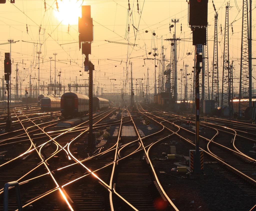
34 Analogy: Railroad Switch
35 Analogy: Railroad Switch x 1 x 2 select f

36 Analogy: Railroad Switch x 1 x 2 select f This is not a perfect analogy because the trains can go in either direction, while the multiplexer would only allow them to go from top to bottom.
37 Truth Table for a 2-1 Multiplexer [ Figure 2.33a from the textbook ]
38 Let s Derive the SOP form
39 Let s Derive the SOP form
40 Let s Derive the SOP form Where should we put the negation signs? s x 1 x 2 s x 1 x 2 s x 1 x 2 s x 1 x 2
41 Let s Derive the SOP form s x 1 x 2 s x 1 x 2 s x 1 x 2 s x 1 x 2
42 Let s Derive the SOP form s x 1 x 2 s x 1 x 2 s x 1 x 2 s x 1 x 2 f (s, x 1, x 2 ) = s x 1 x 2 + s x 1 x 2 + s x 1 x 2 + s x 1 x 2
43 Let s simplify this expression f (s, x 1, x 2 ) = s x 1 x 2 + s x 1 x 2 + s x 1 x 2 + s x 1 x 2
44 Let s simplify this expression f (s, x 1, x 2 ) = s x 1 x 2 + s x 1 x 2 + s x 1 x 2 + s x 1 x 2 f (s, x 1, x 2 ) = s x 1 (x 2 + x 2 ) + s (x 1 +x 1 )x 2
45 Let s simplify this expression f (s, x 1, x 2 ) = s x 1 x 2 + s x 1 x 2 + s x 1 x 2 + s x 1 x 2 f (s, x 1, x 2 ) = s x 1 (x 2 + x 2 ) + s (x 1 +x 1 )x 2 f (s, x 1, x 2 ) = s x 1 + s x 2
46 Circuit for 2-1 Multiplexer x 1 s s x 2 f x 1 x f (b) Circuit (c) Graphical symbol [ Figure 2.33b-c from the textbook ]
47 More Compact Truth-Table Representation s x 1 x 2 f (s, x 1, x 2 ) (a) Truth table s 0 1 f (s, x 1, x 2 ) x 1 x 2 [ Figure 2.33 from the textbook ]
48 4-1 Multiplexer (Definition) Has four inputs: w 0, w 1, w 2, w 3 Also has two select lines: s 1 and s 0 If s 1 =0 and s 0 =0, then the output f is equal to w 0 If s 1 =0 and s 0 =1, then the output f is equal to w 1 If s 1 =1 and s 0 =0, then the output f is equal to w 2 If s 1 =1 and s 0 =1, then the output f is equal to w 3
49 4-1 Multiplexer (Definition) Has four inputs: w 0, w 1, w 2, w 3 Also has two select lines: s 1 and s 0 If s 1 =0 and s 0 =0, then the output f is equal to w 0 If s 1 =0 and s 0 =1, then the output f is equal to w 1 If s 1 =1 and s 0 =0, then the output f is equal to w 2 If s 1 =1 and s 0 =1, then the output f is equal to w 3 We ll talk more about this when we get to chapter 4, but here is a quick preview.
50 Graphical Symbol and Truth Table [ Figure 4.2a-b from the textbook ]
51 The long-form truth table
52 The long-form truth table [
53 The long-form truth table [
54 The long-form truth table [
55 The long-form truth table [
56 4-1 Multiplexer (SOP circuit) [ Figure 4.2c from the textbook ]
57 Using three 2-to-1 multiplexers to build one 4-to-1 multiplexer s 1 s 0 w 0 w f w 2 w [ Figure 4.3 from the textbook ]
58 Analogy: Railroad Switches
59 Analogy: Railroad Switches w 0 w 1 w 2 w 3 s 1 f
60 Analogy: Railroad Switches w 0 w 1 w 2 w 3 s 0 these two switches are controlled together s 1 f
61 Using three 2-to-1 multiplexers to build one 4-to-1 multiplexer
62 Using three 2-to-1 multiplexers to build one 4-to-1 multiplexer
63 Using three 2-to-1 multiplexers to build one 4-to-1 multiplexer
64 Using three 2-to-1 multiplexers to build one 4-to-1 multiplexer w 0 s 1 s 0 w 1 w 2 f w 3
65 That is different from the SOP form of the 4-1 multiplexer shown below, which uses less gates
66 16-1 Multiplexer s 0 s 1 w 0 w 3 w 4 s 2 s 3 w 7 f w 8 w 11 w 12 w 15 [ Figure 4.4 from the textbook ]
67 [
68 Questions?
69 THE END
CprE 281: Digital Logic
 CprE 281: Digital Logic Instructor: Alexander Stoytchev http://www.ece.iastate.edu/~alexs/classes/ Design Examples CprE 281: Digital Logic Iowa State University, Ames, IA Copyright Alexander Stoytchev
CprE 281: Digital Logic
 CprE 281: Digital Logic Instructor: Alexander Stoytchev http://www.ece.iastate.edu/~alexs/classes/ NAND and NOR Logic Networks CprE 281: Digital Logic Iowa State University, Ames, IA Copyright Alexander
CprE 281: Digital Logic
 CprE 281: Digital Logic Instructor: Alexander Stoytchev http://www.ece.iastate.edu/~alexs/classes/ NAND and NOR Logic Networks CprE 281: Digital Logic Iowa State University, Ames, IA Copyright Alexander
CprE 281: Digital Logic
 CprE 28: Digital Logic Instructor: Alexander Stoytchev http://www.ece.iastate.edu/~alexs/classes/ Examples of Solved Problems CprE 28: Digital Logic Iowa State University, Ames, IA Copyright Alexander
CprE 281: Digital Logic
 CprE 28: Digital Logic Instructor: Alexander Stoytchev http://www.ece.iastate.edu/~alexs/classes/ Decoders and Encoders CprE 28: Digital Logic Iowa State University, Ames, IA Copyright Alexander Stoytchev
CprE 281: Digital Logic
 CprE 28: Digital Logic Instructor: Alexander Stoytchev http://www.ece.iastate.edu/~alexs/classes/ Code Converters CprE 28: Digital Logic Iowa State University, Ames, IA Copyright Alexander Stoytchev HW
CprE 281: Digital Logic
 CprE 281: Digital Logic Instructor: Alexander Stoytchev http://www.ece.iastate.edu/~alexs/classes/ Boolean Algebra CprE 281: Digital Logic Iowa State University, Ames, IA Copyright Alexander Stoytchev
CprE 281: Digital Logic
 CprE 281: Digital Logic Instructor: Alexander Stoytchev http://www.ece.iastate.edu/~alexs/classes/ Signed Numbers CprE 281: Digital Logic Iowa State University, Ames, IA Copyright Alexander Stoytchev Administrative
CprE 281: Digital Logic
 CprE 281: Digital Logic Instructor: Alexander Stoytchev http://www.ece.iastate.edu/~alexs/classes/ Fast Adders CprE 281: Digital Logic Iowa State University, Ames, IA Copyright Alexander Stoytchev HW5
CS 226: Digital Logic Design
 CS 226: Digital Logic Design 0 1 1 I S 0 1 0 S Department of Computer Science and Engineering, Indian Institute of Technology Bombay. 1 of 29 Objectives In this lecture we will introduce: 1. Logic functions
2009 Spring CS211 Digital Systems & Lab CHAPTER 2: INTRODUCTION TO LOGIC CIRCUITS
 CHAPTER 2: INTRODUCTION TO LOGIC CIRCUITS What will we learn? 2 Logic functions and circuits Boolean Algebra Logic gates and Synthesis CAD tools and VHDL Read Section 2.9 and 2.0 Terminology 3 Digital
Ex: Boolean expression for majority function F = A'BC + AB'C + ABC ' + ABC.
 Boolean Expression Forms: Sum-of-products (SOP) Write an AND term for each input combination that produces a 1 output. Write the input variable if its value is 1; write its complement otherwise. OR the
CprE 281: Digital Logic
 CprE 281: Digital Logic Instructor: Alexander Stoytchev http://www.ece.iastate.edu/~alexs/classes/ Multiplication CprE 281: Digital Logic Iowa State University, Ames, IA Copyright Alexander Stoytchev HW
Administrative Notes. Chapter 2 <9>
 Administrative Notes Note: New homework instructions starting with HW03 Homework is due at the beginning of class Homework must be organized, legible (messy is not), and stapled to be graded Chapter 2
Experiment 7: Magnitude comparators
 Module: Logic Design Lab Name:... University no:.. Group no: Lab Partner Name: Experiment 7: Magnitude comparators Mr. Mohamed El-Saied Objective: Realization of -bit comparator using logic gates. Realization
211: Computer Architecture Summer 2016
 211: Computer Architecture Summer 2016 Liu Liu Topic: Storage Project3 Digital Logic - Storage: Recap - Review: cache hit rate - Project3 - Digital Logic: - truth table => SOP - simplification: Boolean
Combinational Logic Design Principles
 Combinational Logic Design Principles Switching algebra Doru Todinca Department of Computers Politehnica University of Timisoara Outline Introduction Switching algebra Axioms of switching algebra Theorems
Slide Set 3. for ENEL 353 Fall Steve Norman, PhD, PEng. Electrical & Computer Engineering Schulich School of Engineering University of Calgary
 Slide Set 3 for ENEL 353 Fall 2016 Steve Norman, PhD, PEng Electrical & Computer Engineering Schulich School of Engineering University of Calgary Fall Term, 2016 SN s ENEL 353 Fall 2016 Slide Set 3 slide
Learning Objectives 10/7/2010. CE 411 Digital System Design. Fundamental of Logic Design. Review the basic concepts of logic circuits. Dr.
 /7/ CE 4 Digital ystem Design Dr. Arshad Aziz Fundamental of ogic Design earning Objectives Review the basic concepts of logic circuits Variables and functions Boolean algebra Minterms and materms ogic
Floating Point Representation and Digital Logic. Lecture 11 CS301
 Floating Point Representation and Digital Logic Lecture 11 CS301 Administrative Daily Review of today s lecture w Due tomorrow (10/4) at 8am Lab #3 due Friday (9/7) 1:29pm HW #5 assigned w Due Monday 10/8
CHAPTER1: Digital Logic Circuits Combination Circuits
 CS224: Computer Organization S.KHABET CHAPTER1: Digital Logic Circuits Combination Circuits 1 PRIMITIVE LOGIC GATES Each of our basic operations can be implemented in hardware using a primitive logic gate.
Boolean Algebra and Logic Simplification
 S302 Digital Logic Design Boolean Algebra and Logic Simplification Boolean Analysis of Logic ircuits, evaluating of Boolean expressions, representing the operation of Logic circuits and Boolean expressions
CprE 281: Digital Logic
 CprE 281: igital Logic Instructor: Alexander Stoytchev http://www.ece.iastate.edu/~alexs/classes/ State Minimization CprE 281: igital Logic Iowa State University, Ames, IA Copyright Alexander Stoytchev
Chapter 2 (Lect 2) Canonical and Standard Forms. Standard Form. Other Logic Operators Logic Gates. Sum of Minterms Product of Maxterms
 Canonical and Standard Forms. Standard Form. Other Logic Operators Logic Gates. Sum of Minterms Product of Maxterms") Chapter 2 (Lect 2) Canonical and Standard Forms Sum of Minterms Product of Maxterms Standard Form Sum of products Product of sums Other Logic Operators Logic Gates Basic and Multiple Inputs Positive and
Chapter 2 (Lect 2) Canonical and Standard Forms Sum of Minterms Product of Maxterms Standard Form Sum of products Product of sums Other Logic Operators Logic Gates Basic and Multiple Inputs Positive and
Unit 2 Session - 6 Combinational Logic Circuits
 Objectives Unit 2 Session - 6 Combinational Logic Circuits Draw 3- variable and 4- variable Karnaugh maps and use them to simplify Boolean expressions Understand don t Care Conditions Use the Product-of-Sums
CPE100: Digital Logic Design I
 Professor Brendan Morris, SEB 3216, brendan.morris@unlv.edu CPE100: Digital Logic Design I Midterm01 Review http://www.ee.unlv.edu/~b1morris/cpe100/ 2 Logistics Thursday Oct. 5 th In normal lecture (13:00-14:15)
CSE20: Discrete Mathematics for Computer Science. Lecture Unit 2: Boolan Functions, Logic Circuits, and Implication
 CSE20: Discrete Mathematics for Computer Science Lecture Unit 2: Boolan Functions, Logic Circuits, and Implication Disjunctive normal form Example: Let f (x, y, z) =xy z. Write this function in DNF. Minterm
This form sometimes used in logic circuit, example:
 Objectives: 1. Deriving of logical expression form truth tables. 2. Logical expression simplification methods: a. Algebraic manipulation. b. Karnaugh map (k-map). 1. Deriving of logical expression from
Introduction to Computer Engineering ECE 203
 Introduction to Computer Engineering ECE 203 Northwestern University Department of Electrical Engineering and Computer Science Teacher: Robert Dick Office: L477 Tech Email: dickrp@ece.northwestern.edu
Chapter 2: Switching Algebra and Logic Circuits
 Chapter 2: Switching Algebra and Logic Circuits Formal Foundation of Digital Design In 1854 George Boole published An investigation into the Laws of Thoughts Algebraic system with two values 0 and 1 Used
Combinatorial Logic Design Principles
 Combinatorial Logic Design Principles ECGR2181 Chapter 4 Notes Logic System Design I 4-1 Boolean algebra a.k.a. switching algebra deals with boolean values -- 0, 1 Positive-logic convention analog voltages
Lecture 6: Manipulation of Algebraic Functions, Boolean Algebra, Karnaugh Maps
 EE210: Switching Systems Lecture 6: Manipulation of Algebraic Functions, Boolean Algebra, Karnaugh Maps Prof. YingLi Tian Feb. 21/26, 2019 Department of Electrical Engineering The City College of New York
Lecture 2 Review on Digital Logic (Part 1)
") Lecture 2 Review on Digital Logic (Part 1) Xuan Silvia Zhang Washington University in St. Louis http://classes.engineering.wustl.edu/ese461/ Grading Engagement 5% Review Quiz 10% Homework 10% Labs 40%
Lecture 2 Review on Digital Logic (Part 1) Xuan Silvia Zhang Washington University in St. Louis http://classes.engineering.wustl.edu/ese461/ Grading Engagement 5% Review Quiz 10% Homework 10% Labs 40%
Chapter 2 Combinational Logic Circuits
 Logic and Computer Design Fundamentals Chapter 2 Combinational Logic Circuits Part 1 Gate Circuits and Boolean Equations Chapter 2 - Part 1 2 Chapter 2 - Part 1 3 Chapter 2 - Part 1 4 Chapter 2 - Part
Logic Design. Chapter 2: Introduction to Logic Circuits
 Logic Design Chapter 2: Introduction to Logic Circuits Introduction Logic circuits perform operation on digital signal Digital signal: signal values are restricted to a few discrete values Binary logic
L4: Karnaugh diagrams, two-, and multi-level minimization. Elena Dubrova KTH / ICT / ES
 L4: Karnaugh diagrams, two-, and multi-level minimization Elena Dubrova KTH / ICT / ES dubrova@kth.se Combinatorial system a(t) not(a(t)) A combinatorial system has no memory - its output depends therefore
Overview. Multiplexor. cs281: Introduction to Computer Systems Lab02 Basic Combinational Circuits: The Mux and the Adder
 cs281: Introduction to Computer Systems Lab02 Basic Combinational Circuits: The Mux and the Adder Overview The objective of this lab is to understand two basic combinational circuits the multiplexor and
Digital Logic Design ABC. Representing Logic Operations. Dr. Kenneth Wong. Determining output level from a diagram. Laws of Boolean Algebra
 Digital Logic Design ENGG1015 1 st Semester, 2011 Representing Logic Operations Each function can be represented equivalently in 3 ways: Truth table Boolean logic expression Schematics Truth Table Dr.
CprE 281: Digital Logic
 CprE 281: Digital Logic Instructor: Alexander Stoytchev http://www.ece.iastate.edu/~alexs/classes/ Synchronous Sequential Circuits Basic Design Steps CprE 281: Digital Logic Iowa State University, Ames,
Digital Logic. CS211 Computer Architecture. l Topics. l Transistors (Design & Types) l Logic Gates. l Combinational Circuits.
 l Logic Gates. l Combinational Circuits.") CS211 Computer Architecture Digital Logic l Topics l Transistors (Design & Types) l Logic Gates l Combinational Circuits l K-Maps Figures & Tables borrowed from:! http://www.allaboutcircuits.com/vol_4/index.html!
CS211 Computer Architecture Digital Logic l Topics l Transistors (Design & Types) l Logic Gates l Combinational Circuits l K-Maps Figures & Tables borrowed from:! http://www.allaboutcircuits.com/vol_4/index.html!
Lecture 5: NAND, NOR and XOR Gates, Simplification of Algebraic Expressions
 EE210: Switching Systems Lecture 5: NAND, NOR and XOR Gates, Simplification of Algebraic Expressions Prof. YingLi Tian Feb. 15, 2018 Department of Electrical Engineering The City College of New York The
Chapter 2: Princess Sumaya Univ. Computer Engineering Dept.
 hapter 2: Princess Sumaya Univ. omputer Engineering Dept. Basic Definitions Binary Operators AND z = x y = x y z=1 if x=1 AND y=1 OR z = x + y z=1 if x=1 OR y=1 NOT z = x = x z=1 if x=0 Boolean Algebra
Digital Circuit And Logic Design I. Lecture 4
 Digital Circuit And Logic Design I Lecture 4 Outline Combinational Logic Design Principles (2) 1. Combinational-circuit minimization 2. Karnaugh maps 3. Quine-McCluskey procedure Panupong Sornkhom, 2005/2
Functions. Computers take inputs and produce outputs, just like functions in math! Mathematical functions can be expressed in two ways:
 Boolean Algebra (1) Functions Computers take inputs and produce outputs, just like functions in math! Mathematical functions can be expressed in two ways: An expression is finite but not unique f(x,y)
XI STANDARD [ COMPUTER SCIENCE ] 5 MARKS STUDY MATERIAL.
![XI STANDARD [ COMPUTER SCIENCE ] 5 MARKS STUDY MATERIAL.](/thumbs/81/84726747.jpg "XI STANDARD [ COMPUTER SCIENCE ] 5 MARKS STUDY MATERIAL.") 2017-18 XI STANDARD [ COMPUTER SCIENCE ] 5 MARKS STUDY MATERIAL HALF ADDER 1. The circuit that performs addition within the Arithmetic and Logic Unit of the CPU are called adders. 2. A unit that adds two
2017-18 XI STANDARD [ COMPUTER SCIENCE ] 5 MARKS STUDY MATERIAL HALF ADDER 1. The circuit that performs addition within the Arithmetic and Logic Unit of the CPU are called adders. 2. A unit that adds two
Boolean algebra. Examples of these individual laws of Boolean, rules and theorems for Boolean algebra are given in the following table.
 The Laws of Boolean Boolean algebra As well as the logic symbols 0 and 1 being used to represent a digital input or output, we can also use them as constants for a permanently Open or Closed circuit or
Standard Expression Forms
 ThisLecture will cover the following points: Canonical and Standard Forms MinTerms and MaxTerms Digital Logic Families 24 March 2010 Standard Expression Forms Two standard (canonical) expression forms
Digital Circuit And Logic Design I. Lecture 3
 Digital Circuit And Logic Design I Lecture 3 Outline Combinational Logic Design Principles (). Introduction 2. Switching algebra 3. Combinational-circuit analysis 4. Combinational-circuit synthesis Panupong
Chapter 4 Optimized Implementation of Logic Functions
 Chapter 4 Optimized Implementation of Logic Functions Logic Minimization Karnaugh Maps Systematic Approach for Logic Minimization Minimization of Incompletely Specified Functions Tabular Method for Minimization
CMSC 313 Lecture 17. Focus Groups. Announcement: in-class lab Thu 10/30 Homework 3 Questions Circuits for Addition Midterm Exam returned
 Focus Groups CMSC 33 Lecture 7 Need good sample of all types of CS students Mon /7 & Thu /2, 2:3p-2:p & 6:p-7:3p Announcement: in-class lab Thu /3 Homework 3 Questions Circuits for Addition Midterm Exam
Slides for Lecture 10
 Slides for Lecture 10 ENEL 353: Digital Circuits Fall 2013 Term Steve Norman, PhD, PEng Electrical & Computer Engineering Schulich School of Engineering University of Calgary 30 September, 2013 ENEL 353
Combinational Logic Fundamentals
 Topic 3: Combinational Logic Fundamentals In this note we will study combinational logic, which is the part of digital logic that uses Boolean algebra. All the concepts presented in combinational logic
ECE 2300 Digital Logic & Computer Organization
 ECE 23 Digital Logic & Computer Organization Spring 28 Combinational Building Blocks Lecture 5: Announcements Lab 2 prelab due tomorrow HW due Friday HW 2 to be posted on Thursday Lecture 4 to be replayed
Combinational Logic. Review of Combinational Logic 1
 Combinational Logic! Switches -> Boolean algebra! Representation of Boolean functions! Logic circuit elements - logic gates! Regular logic structures! Timing behavior of combinational logic! HDLs and combinational
Chapter 2 Combinational Logic Circuits
 Logic and Computer Design Fundamentals Chapter 2 Combinational Logic Circuits Part 3 Additional Gates and Circuits Charles Kime & Thomas Kaminski 2008 Pearson Education, Inc. (Hyperlinks are active in
Numbers & Arithmetic. Hakim Weatherspoon CS 3410, Spring 2012 Computer Science Cornell University. See: P&H Chapter , 3.2, C.5 C.
 Numbers & Arithmetic Hakim Weatherspoon CS 3410, Spring 2012 Computer Science Cornell University See: P&H Chapter 2.4-2.6, 3.2, C.5 C.6 Example: Big Picture Computer System Organization and Programming
EECS Variable Logic Functions
 EECS150 Section 1 Introduction to Combinational Logic Fall 2001 2-Variable Logic Functions There are 16 possible functions of 2 input variables: in general, there are 2**(2**n) functions of n inputs X
COMPUTER ENGINEERING PROGRAM
 COMPUTER ENGINEERING PROGRAM California Polytechnic State University CPE 169 Experiment 3 Introduction to Function Reduction, Implementation, and Function Forms Learning Objectives 1. Digital Logic To
Cover Sheet for Lab Experiment #3
 The University of Toledo EECS:1100 R2 Digital Logic Design Dr. Anthony D. Johnson Cover Sheet for Lab Experiment #3 Student Names Course Section Anthony Phillips 003 Alexander Beck 003 Report turned in
Designing Information Devices and Systems II Spring 2016 Anant Sahai and Michel Maharbiz Homework 5. This homework is due February 29, 2016, at Noon.
 EECS 16 Designing Information Devices and Systems II Spring 2016 nant Sahai and Michel Maharbiz Homework 5 This homework is due February 29, 2016, at Noon. 1. Homework process and study group Who else
EEE130 Digital Electronics I Lecture #4
 EEE130 Digital Electronics I Lecture #4 - Boolean Algebra and Logic Simplification - By Dr. Shahrel A. Suandi Topics to be discussed 4-1 Boolean Operations and Expressions 4-2 Laws and Rules of Boolean
Karnaugh Maps (K-Maps)
") Karnaugh Maps (K-Maps) Boolean expressions can be minimized by combining terms P + P = P K-maps minimize equations graphically Put terms to combine close to one another B C C B B C BC BC BC BC BC BC BC
Karnaugh Maps (K-Maps) Boolean expressions can be minimized by combining terms P + P = P K-maps minimize equations graphically Put terms to combine close to one another B C C B B C BC BC BC BC BC BC BC
Slides for Lecture 19
 Slides for Lecture 19 ENEL 353: Digital Circuits Fall 2013 Term Steve Norman, PhD, PEng Electrical & Computer Engineering Schulich School of Engineering University of Calgary 23 October, 2013 ENEL 353
ELEC Digital Logic Circuits Fall 2014 Switching Algebra (Chapter 2)
") ELEC 2200-002 Digital Logic Circuits Fall 2014 Switching Algebra (Chapter 2) Vishwani D. Agrawal James J. Danaher Professor Department of Electrical and Computer Engineering Auburn University, Auburn,
ELEC 2200-002 Digital Logic Circuits Fall 2014 Switching Algebra (Chapter 2) Vishwani D. Agrawal James J. Danaher Professor Department of Electrical and Computer Engineering Auburn University, Auburn,
CPE100: Digital Logic Design I
 Chapter 2 Professor Brendan Morris, SEB 3216, brendan.morris@unlv.edu http://www.ee.unlv.edu/~b1morris/cpe100/ CPE100: Digital Logic Design I Section 1004: Dr. Morris Combinational Logic Design Chapter
Goals for Lecture. Binary Logic and Gates (MK 2.1) Binary Variables. Notation Examples. Logical Operations
 Binary Variables. Notation Examples. Logical Operations") Introduction to Electrical Engineering, II LETURE NOTES #2 Instructor: Email: Telephone: Office: ndrew. Kahng (lecture) abk@ucsd.edu 858-822-4884 office 3802 P&M lass Website: http://vlsicad.ucsd.edu/courses/ece20b/wi04/
Introduction to Electrical Engineering, II LETURE NOTES #2 Instructor: Email: Telephone: Office: ndrew. Kahng (lecture) abk@ucsd.edu 858-822-4884 office 3802 P&M lass Website: http://vlsicad.ucsd.edu/courses/ece20b/wi04/
University of Toronto Faculty of Applied Science and Engineering Department of Electrical and Computer Engineering Midterm Examination
 University of Toronto Faculty of Applied Science and Engineering Department of Electrical and Computer Engineering Midterm Eamination ECE 241F - Digital Systems Wednesday October 11, 2006, 6:00 7:30 pm
WEEK 2.1 BOOLEAN ALGEBRA
 WEEK 2.1 BOOLEAN ALGEBRA 1 Boolean Algebra Boolean algebra was introduced in 1854 by George Boole and in 1938 was shown by C. E. Shannon to be useful for manipulating Boolean logic functions. The postulates
CMSC 313 Lecture 18 Midterm Exam returned Assign Homework 3 Circuits for Addition Digital Logic Components Programmable Logic Arrays
 MS 33 Lecture 8 Midterm Exam returned Assign Homework 3 ircuits for Addition Digital Logic omponents Programmable Logic Arrays UMB, MS33, Richard hang MS 33, omputer Organization & Assembly
Simplification of Boolean Functions. Dept. of CSE, IEM, Kolkata
 Simplification of Boolean Functions Dept. of CSE, IEM, Kolkata 1 Simplification of Boolean Functions: An implementation of a Boolean Function requires the use of logic gates. A smaller number of gates,
Chapter 3 Combinational Logic Design
 Logic and Computer Design Fundamentals Chapter 3 Combinational Logic Design Part 1- Implementation Technology and Logic Design Overview Part 1-Implementation Technology and Logic Design Design Concepts
Chapter 2 Boolean Algebra and Logic Gates
 Chapter 2 Boolean Algebra and Logic Gates The most common postulates used to formulate various algebraic structures are: 1. Closure. N={1,2,3,4 }, for any a,b N we obtain a unique c N by the operation
Logic Design Combinational Circuits. Digital Computer Design
 Logic Design Combinational Circuits Digital Computer Design Topics Combinational Logic Karnaugh Maps Combinational uilding locks Timing 2 Logic Circuit logic circuit is composed of: Inputs Outputs Functional
MC9211 Computer Organization
 MC92 Computer Organization Unit : Digital Fundamentals Lesson2 : Boolean Algebra and Simplification (KSB) (MCA) (29-2/ODD) (29 - / A&B) Coverage Lesson2 Introduces the basic postulates of Boolean Algebra
ECE 545 Digital System Design with VHDL Lecture 1A. Digital Logic Refresher Part A Combinational Logic Building Blocks
 ECE 545 Digital System Design with VHDL Lecture A Digital Logic Refresher Part A Combinational Logic Building Blocks Lecture Roadmap Combinational Logic Basic Logic Review Basic Gates De Morgan s Laws
Circuits & Boolean algebra.
 Circuits & Boolean algebra http://xkcd.com/730/ CSCI 255: Introduction to Embedded Systems Keith Vertanen Copyright 2011 Digital circuits Overview How a switch works Building basic gates from switches
CSE140: Components and Design Techniques for Digital Systems. Introduction. Instructor: Mohsen Imani
 CSE4: Components and Design Techniques for Digital Systems Introduction Instructor: Mohsen Imani Slides from: Prof.Tajana Simunic Rosing & Dr.Pietro Mercati Welcome to CSE 4! Instructor: Mohsen Imani Email:
E40M. Binary Numbers. M. Horowitz, J. Plummer, R. Howe 1
 E40M Binary Numbers M. Horowitz, J. Plummer, R. Howe 1 Reading Chapter 5 in the reader A&L 5.6 M. Horowitz, J. Plummer, R. Howe 2 Useless Box Lab Project #2 Adding a computer to the Useless Box alows us
Simplifying Logic Circuits with Karnaugh Maps
 Simplifying Logic Circuits with Karnaugh Maps The circuit at the top right is the logic equivalent of the Boolean expression: f = abc + abc + abc Now, as we have seen, this expression can be simplified
Number System conversions
 Number System conversions Number Systems The system used to count discrete units is called number system. There are four systems of arithmetic which are often used in digital electronics. Decimal Number
Theorem/Law/Axioms Over (.) Over (+)
 Over (+)") material prepared by: MUKESH OHR Follow me on F : http://www.facebook.com/mukesh.sirji4u OOLEN LGER oolean lgebra is a set of rules, laws and theorems by which logical operations can be mathematically
material prepared by: MUKESH OHR Follow me on F : http://www.facebook.com/mukesh.sirji4u OOLEN LGER oolean lgebra is a set of rules, laws and theorems by which logical operations can be mathematically
ENGR 303 Introduction to Logic Design Lecture 3. Dr. Chuck Brown Engineering and Computer Information Science Folsom Lake College
 Introduction to Logic Design Lecture 3 Dr. Chuck rown Engineering and Computer Information Science Folsom Lake College Outline for Todays Lecture Logic Circuits SOP / POS oolean Theorems DeMorgan s Theorem
Combinational Logic. By : Ali Mustafa
 Combinational Logic By : Ali Mustafa Contents Adder Subtractor Multiplier Comparator Decoder Encoder Multiplexer How to Analyze any combinational circuit like this? Analysis Procedure To obtain the output
ENG2410 Digital Design Combinational Logic Circuits
 ENG240 Digital Design Combinational Logic Circuits Fall 207 S. Areibi School of Engineering University of Guelph Binary variables Binary Logic Can be 0 or (T or F, low or high) Variables named with single
II. COMBINATIONAL LOGIC DESIGN. - algebra defined on a set of 2 elements, {0, 1}, with binary operators multiply (AND), add (OR), and invert (NOT):
, add (OR), and invert (NOT):") ENGI 386 Digital Logic II. COMBINATIONAL LOGIC DESIGN Combinational Logic output of digital system is only dependent on current inputs (i.e., no memory) (a) Boolean Algebra - developed by George Boole
ENGI 386 Digital Logic II. COMBINATIONAL LOGIC DESIGN Combinational Logic output of digital system is only dependent on current inputs (i.e., no memory) (a) Boolean Algebra - developed by George Boole
Chapter 2 Boolean Algebra and Logic Gates
 Ch1: Digital Systems and Binary Numbers Ch2: Ch3: Gate-Level Minimization Ch4: Combinational Logic Ch5: Synchronous Sequential Logic Ch6: Registers and Counters Switching Theory & Logic Design Prof. Adnan
UNIT 4 MINTERM AND MAXTERM EXPANSIONS
 UNIT 4 MINTERM AND MAXTERM EXPANSIONS Spring 2 Minterm and Maxterm Expansions 2 Contents Conversion of English sentences to Boolean equations Combinational logic design using a truth table Minterm and
NAND, NOR and XOR functions properties
 Laboratory NAND, NOR and XOR functions properties. Laboratory work goals Enumeration of NAND, NOR and XOR functions properties Presentation of NAND, NOR and XOR modules Realisation of circuits with gates
CMSC 313 Lecture 16 Announcement: no office hours today. Good-bye Assembly Language Programming Overview of second half on Digital Logic DigSim Demo
 CMSC 33 Lecture 6 nnouncement: no office hours today. Good-bye ssembly Language Programming Overview of second half on Digital Logic DigSim Demo UMC, CMSC33, Richard Chang Good-bye ssembly
Boolean Algebra. The Building Blocks of Digital Logic Design. Section. Section Overview. Binary Operations and Their Representation.
 Section 3 Boolean Algebra The Building Blocks of Digital Logic Design Section Overview Binary Operations (AND, OR, NOT), Basic laws, Proof by Perfect Induction, De Morgan s Theorem, Canonical and Standard
Chapter 7 Logic Circuits
 Chapter 7 Logic Circuits Goal. Advantages of digital technology compared to analog technology. 2. Terminology of Digital Circuits. 3. Convert Numbers between Decimal, Binary and Other forms. 5. Binary
Combinational Logic Circuits Part II -Theoretical Foundations
 Combinational Logic Circuits Part II -Theoretical Foundations Overview Boolean Algebra Basic Logic Operations Basic Identities Basic Principles, Properties, and Theorems Boolean Function and Representations
EXPERIMENT #4: SIMPLIFICATION OF BOOLEAN FUNCTIONS
 EXPERIMENT #4: SIMPLIFICATION OF BOOLEAN FUNCTIONS OBJECTIVES: Simplify Boolean functions using K-map method Obtain Boolean expressions from timing diagrams Design and implement logic circuits Equipment
CMPE12 - Notes chapter 1. Digital Logic. (Textbook Chapter 3)
") CMPE12 - Notes chapter 1 Digital Logic (Textbook Chapter 3) Transistor: Building Block of Computers Microprocessors contain TONS of transistors Intel Montecito (2005): 1.72 billion Intel Pentium 4 (2000):
CMPE12 - Notes chapter 1 Digital Logic (Textbook Chapter 3) Transistor: Building Block of Computers Microprocessors contain TONS of transistors Intel Montecito (2005): 1.72 billion Intel Pentium 4 (2000):
ELCT201: DIGITAL LOGIC DESIGN
 ELCT2: DIGITAL LOGIC DESIGN Dr. Eng. Haitham Omran, haitham.omran@guc.edu.eg Dr. Eng. Wassim Alexan, wassim.joseph@guc.edu.eg Lecture 2 Following the slides of Dr. Ahmed H. Madian ذو الحجة 438 ه Winter
Computer Organization I. Lecture 13: Design of Combinational Logic Circuits
 Computer Organization I Lecture 13: Design of Combinational Logic Circuits Overview The optimization of multiple-level circuits Mapping Technology Verification Objectives To know how to optimize the multiple-level
Logic Design I (17.341) Fall Lecture Outline
 Fall Lecture Outline") Logic Design I (17.341) Fall 2011 Lecture Outline Class # 06 October 24, 2011 Dohn Bowden 1 Today s Lecture Administrative Main Logic Topic Homework 2 Course Admin 3 Administrative Admin for tonight Syllabus
Logic Design I (17.341) Fall 2011 Lecture Outline Class # 06 October 24, 2011 Dohn Bowden 1 Today s Lecture Administrative Main Logic Topic Homework 2 Course Admin 3 Administrative Admin for tonight Syllabus
BOOLEAN ALGEBRA CLASS XII. Presented By : Dinesh Patel PGT CS KV IIT Powai
 BOOLEAN ALGEBRA CLASS II Presented By : Dinesh Patel PGT CS KV IIT Powai Introduction Boolean Algebra is a set of rules and regulation which is suitable for Digital Circuits, whose answer is either True
Chapter 2 Combinational Logic Circuits
 Logic and Computer Design Fundamentals Chapter 2 Combinational Logic Circuits Part 1 Gate Circuits and Boolean Equations Charles Kime & Thomas Kaminski 2008 Pearson Education, Inc. (Hyperlinks are active