CLASS Fourth Units (Second part)
|
|
|
- Gary Clarke
- 5 years ago
- Views:
Transcription
1 CLASS Fourth Units (Second part)
2 Energy analysis of closed systems Copyright The McGraw-Hill Companies, Inc. Permission required for reproduction or display.


3 MOVING BOUNDARY WORK Moving boundary work (P dv work): The expansion and compression work in a piston-cylinder device. Quasi-equilibrium process: A process during which the system remains nearly in equilibrium at all times. W b is positive for expansion W b is negative for compression The work associated with a moving boundary is called boundary work. A gas does a differential amount of work W b as it forces the piston to move by a differential amount ds. 3
4 The boundary work done during a process depends on the path followed as well as the end states. The area under the process curve on a P-V diagram represents the boundary work. The net work done during a cycle is the difference between the work done by the system and the work done on the system. 4
5 Boundary work for a constant-volume process
6 Boundary work for a constant-pressure process
 Constant pressure process What is the boundary work for a constantvolume process? Schematic and P-V diagram for a polytropic process.")
7 Polytropic, Isothermal, and Isobaric processes Polytropic process: C, n (polytropic exponent) constants Polytropic process Polytropic and for ideal gas When n = 1 (isothermal process) Constant pressure process What is the boundary work for a constantvolume process? Schematic and P-V diagram for a polytropic process. 7

8 Boundary work for a constant-pressure process


9 ENERGY BALANCE FOR CLOSED SYSTEMS Energy balance for any system undergoing any process Energy balance in the rate form The total quantities are related to the quantities per unit time is Energy balance per unit mass basis Energy balance for a cycle Energy balance in differential form 9

10 Energy balance when sign convention is used (i.e., heat input and work output are positive; heat output and work input are negative). For a cycle E = 0, thus Q = W. Various forms of the first-law relation for closed systems when sign convention is used. The first law cannot be proven mathematically, but no process in nature is known to have violated the first law, and this should be taken as sufficient proof. 10


11 Energy balance for a constant-pressure expansion or compression process General analysis for a closed system undergoing a quasi-equilibrium constant-pressure process. Q is to the system and W is from the system. For a constant-pressure expansion or compression process: U W H b An example of constant-pressure process 11


12 SPECIFIC HEATS Specific heat at constant volume, c v : The energy required to raise the temperature of the unit mass of a substance by one degree as the volume is maintained constant. Specific heat at constant pressure, c p : The energy required to raise the temperature of the unit mass of a substance by one degree as the pressure is maintained constant. Specific heat is the energy required to raise the temperature of a unit mass of a substance by one degree in a specified way. Constantvolume and constantpressure specific heats c v and c p (values are for helium gas). 12


13 The equations in the figure are valid for any substance undergoing any process. c v and c p are properties. c v is related to the changes in internal energy and c p to the changes in enthalpy. A common unit for specific heats is kj/kg C or kj/kg K. Are these units identical? Formal definitions of c v and c p. The specific heat of a substance changes with temperature. True or False? c p is always greater than c v. 13


14 INTERNAL ENERGY, ENTHALPY, AND SPECIFIC HEATS OF IDEAL GASES Joule showed using this experimental apparatus that u=u(t) For ideal gases, u, h, c v, and c p vary with temperature only. Internal energy and enthalpy change of an ideal gas 14
15 At low pressures, all real gases approach ideal-gas behavior, and therefore their specific heats depend on temperature only. The specific heats of real gases at low pressures are called ideal-gas specific heats, or zero-pressure specific heats, and are often denoted c p0 and c v0. u and h data for a number of gases have been tabulated. These tables are obtained by choosing an arbitrary reference point and performing the integrations by treating state 1 as the reference state. Ideal-gas constantpressure specific heats for some gases (see Table A 2c for c p equations). In the preparation of ideal-gas tables, 0 K is chosen as the reference temperature. 15
16 Internal energy and enthalpy change when specific heat is taken constant at an average value (kj/kg) For small temperature intervals, the specific heats may be assumed to vary linearly with temperature. The relation u = c v T is valid for any kind of process, constantvolume or not. 16
 as a function of temperature and performing the integrations.")
17 Three ways of calculating u and h 1. By using the tabulated u and h data. This is the easiest and most accurate way when tables are readily available. 2. By using the c v or c p relations (Table A-2c) as a function of temperature and performing the integrations. This is very inconvenient for hand calculations but quite desirable for computerized calculations. The results obtained are very accurate. 3. By using average specific heats. This is very simple and certainly very convenient when property tables are not available. The results obtained are reasonably accurate if the temperature interval is not very large. Three ways of calculating u. 17
, its value is essentially constant at 1.667.")
18 Specific Heat Relations of Ideal Gases The relationship between c p, c v and R dh = c p dt and du = c v dt On a molar basis Specific heat ratio The c p of an ideal gas can be determined from a knowledge of c v and R. The specific ratio varies with temperature, but this variation is very mild. For monatomic gases (helium, argon, etc.), its value is essentially constant at Many diatomic gases, including air, have a specific heat ratio of about 1.4 at room temperature. 18
 is constant.")

19 INTERNAL ENERGY, ENTHALPY, AND SPECIFIC HEATS OF SOLIDS AND LIQUIDS Incompressible substance: A substance whose specific volume (or density) is constant. Solids and liquids are incompressible substances. The specific volumes of incompressible substances remain constant during a process. The c v and c p values of incompressible substances are identical and are denoted by c. 19
20 Internal Energy Changes Enthalpy Changes A more accurate relation than The enthalpy of a compressed liquid 20
21 Energy analysis of open systems Copyright The McGraw-Hill Companies, Inc. Permission required for reproduction or display.
22 FLOW WORK AND THE ENERGY OF A FLOWING FLUID Flow work, or flow energy: The work (or energy) required to push the mass into or out of the control volume. This work is necessary for maintaining a continuous flow through a control volume. Schematic for flow work. In the absence of acceleration, the force applied on a fluid by a piston is equal to the force applied on the piston by the fluid. 22

23 Total Energy of a Flowing Fluid h = u + Pv The flow energy is automatically taken care of by enthalpy. In fact, this is the main reason for defining the property enthalpy. The total energy consists of three parts for a nonflowing fluid and four parts for a flowing fluid. 23

24 Energy Transport by Mass When the kinetic and potential energies of a fluid stream are negligible When the properties of the mass at each inlet or exit change with time as well as over the cross section The product m i i is the energy transported into control volume by mass per unit time. 24
25 ENERGY ANALYSIS OF STEADY-FLOW SYSTEMS 2 2 V V Qnet, in Wshaft, net, in m h gz m h gz out 2 in 2 For steady flow, time rate of change of the energy content of the CV is zero. This equation states: the net rate of energy transfer to a CV by heat and work transfers during steady flow is equal to the difference between the rates of outgoing and incoming energy flows with mass.


26 ENERGY ANALYSIS OF STEADY-FLOW SYSTEMS Many engineering systems such as power plants operate under steady conditions. Under steady-flow conditions, the mass and energy contents of a control volume remain constant. Under steady-flow conditions, the fluid properties at an inlet or exit remain constant (do not change with time). 26

27 Mass and Energy balances for a steady-flow process Mass balance A water heater in steady operation. Energy balance 27

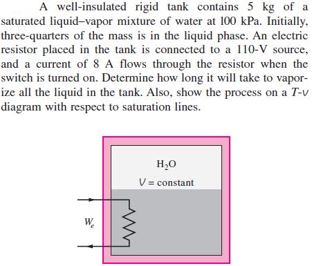
28 Energy balance relations with sign conventions (i.e., heat input and work output are positive) when kinetic and potential energy changes are negligible Some energy unit equivalents Under steady operation, shaft work and electrical work are the only forms of work a simple compressible system may involve. 28
, for example, operate nonstop for months before the system is shut down for maintenance.")
29 SOME STEADY-FLOW ENGINEERING DEVICES Many engineering devices operate essentially under the same conditions for long periods of time. The components of a steam power plant (turbines, compressors, heat exchangers, and pumps), for example, operate nonstop for months before the system is shut down for maintenance. Therefore, these devices can be conveniently analyzed as steady-flow devices. A modern land-based gas turbine used for electric power production. This is a General Electric LM5000 turbine. It has a length of 6.2 m, it weighs 12.5 tons, and produces 55.2 MW at 3600 rpm with steam injection. At very high velocities, even small changes in velocities can cause significant changes in the kinetic energy of the fluid. 29

30 Nozzles and Diffusers Nozzles and diffusers are commonly utilized in jet engines, rockets, spacecraft, and even garden hoses. A nozzle is a device that increases the velocity of a fluid at the expense of pressure. A diffuser is a device that increases the pressure of a fluid by slowing it down. The cross-sectional area of a nozzle decreases in the flow direction for subsonic flows and increases for supersonic flows. The reverse is true for diffusers. Nozzles and diffusers are shaped so that they cause large changes in fluid velocities and thus kinetic energies. Energy balance for a nozzle or diffuser: 30

31 Turbines and Compressors Energy balance for the compressor in this figure: Turbine drives the electric generator In steam, gas, or hydroelectric power plants. As the fluid passes through the turbine, work is done against the blades, which are attached to the shaft. As a result, the shaft rotates, and the turbine produces work. Compressors, as well as pumps and fans, are devices used to increase the pressure of a fluid. Work is supplied to these devices from an external source through a rotating shaft. A fan increases the pressure of a gas slightly and is mainly used to mobilize a gas. A compressor is capable of compressing the gas to very high pressures. Pumps work very much like compressors except that they handle liquids instead of gases. 31

32 Throttling valves Throttling valves are any kind of flow-restricting devices that cause a significant pressure drop in the fluid. What is the difference between a turbine and a throttling valve? The pressure drop in the fluid is often accompanied by a large drop in temperature, and for that reason throttling devices are commonly used in refrigeration and airconditioning applications. Energy balance The temperature of an ideal gas does not change during a throttling (h = constant) process since h = h(t). During a throttling process, the enthalpy of a fluid remains constant. But internal and flow energies may be converted to each other. 32

33 Mixing chambers 60 C In engineering applications, the section where the mixing process takes place is commonly referred to as a mixing chamber. 140 kpa 10 C 43 C Energy balance for the adiabatic mixing chamber in the figure is: The T-elbow of an ordinary shower serves as the mixing chamber for the hot- and the cold-water streams. 33


34 Heat exchangers Heat exchangers are devices where two moving fluid streams exchange heat without mixing. Heat exchangers are widely used in various industries, and they come in various designs. The heat transfer associated with a heat exchanger may be zero or nonzero depending on how the control volume is selected. Mass and energy balances for the adiabatic heat exchanger in the figure is: A heat exchanger can be as simple as two concentric pipes. 34


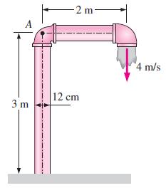
35 Pipe and duct fow The transport of liquids or gases in pipes and ducts is of great importance in many engineering applications. Flow through a pipe or a duct usually satisfies the steady-flow conditions. Pipe or duct flow may involve more than one form of work at the same time. Heat losses from a hot fluid flowing through an uninsulated pipe or duct to the cooler environment may be very significant. Energy balance for the pipe flow shown in the figure is 35

36 ENERGY ANALYSIS OF STEADY-FLOW SYSTEMS For single-stream devices, mass flow rate is constant. V V q w h h g z z 2 P V P V w gz gz u u q net, in shaft, net, in shaft, net, in net, in P V P V gz1 wpump gz2 wturbine emech, loss

37 ENERGY ANALYSIS OF STEADY-FLOW SYSTEMS Divide by g to get each term in units of length P V P V z1 hpump z2 hturbine hl 1g 2g 2g 2g Magnitude of each term is now expressed as an equivalent column height of fluid, i.e., Head
38 The Bernoulli Equation If we neglect piping losses, and have a system without pumps or turbines P V P V z1 z2 1g 2g 2g 2g This is the Bernoulli equation It can also be derived using Newton's second law of motion (see text, p. 187). 3 terms correspond to: Static, dynamic, and hydrostatic head (or pressure).

39 HGL and EGL It is often convenient to plot mechanical energy graphically using heights. Hydraulic Grade Line HGL P g z Energy Grade Line (or total energy) 2 P V EGL z g 2g

40 The Bernoulli Equation The Bernoulli equation is an approximate relation between pressure, velocity, and elevation and is valid in regions of steady, incompressible flow where net frictional forces are negligible. Equation is useful in flow regions outside of boundary layers and wakes.
41 The Bernoulli Equation Limitations on the use of the Bernoulli Equation Steady flow: d/dt = 0 Frictionless flow No shaft work: w pump =w turbine =0 Incompressible flow: = constant No heat transfer: q net,in =0 Applied along a streamline (except for irrotational flow)
42 Mechanical Energy Mechanical energy can be defined as the form of energy that can be converted to mechanical work completely and directly by an ideal mechanical device such as an ideal turbine. Flow P/, kinetic V 2 /g, and potential gz energy are the forms of mechanical energy e mech = P/ V 2 /g + gz Mechanical energy change of a fluid during incompressible flow becomes 2 2 P2 P1 V2 V1 e mech g z z In the absence of loses, e mech represents the work supplied to the fluid ( e mech >0) or extracted from the fluid ( e mech <0).

43 Copyright The McGraw-Hill Companies, Inc. Permission required for reproduction or display. example Consider a river flowing toward a lake at an average velocity of 3 m/s at a rate of 500 m 3 /s at a location 90 m above the lake surface. Determine the total mechanical energy of the river water per unit mass and the power generation potential of the entire river at that location. 3-6
44 Efficiency Transfer of e mech is usually accomplished by a rotating shaft: shaft work Pump, fan, propulsion: receives shaft work (e.g., from an electric motor) and transfers it to the fluid as mechanical energy Turbine: converts e mech of a fluid to shaft work. In the absence of irreversibilities (e.g., friction), mechanical efficiency of a device or process can be defined as E E hmech 1 E E mech, out mech, loss mech, in mech, in If h mech < 100%, losses have occurred during conversion.
45 Pump and Turbine Efficiencies In fluid systems, we are usually interested in increasing the pressure, velocity, and/or elevation of a fluid. In these cases, efficiency is better defined as the ratio of (supplied or extracted work) vs. rate of increase in mechanical energy h h pump turbine E W W E mech, fluid shaft, in shaft, out mech, fluid Overall efficiency must include motor or generator efficiency.

46 Copyright The McGraw-Hill Companies, Inc. Permission required for reproduction or display. In a hydroelectric power plant, 120 m 3 /s of water flows from an elevation of 100 m to a turbine, where electric power is generated. The overall efficiency of the turbine generator is 80 percent. Disregarding frictional losses in piping, estimate the electric power output of this plant. 3-6 Example:
47 Example: A garden hose attached with a nozzle is used to fill a 20-gal bucket. The inner diameter of the hose is 1 in and it reduces to 0.5 in at the nozzle exit. If the average velocity in the hose is 8 ft/s, determine: (a) the volume and mass flow rates of water through the hose (b) how long it will take to fill the bucket with water, and (c) the average velocity of water at the nozzle exit.
48 Example:
49 Example: Water flows through a horizontal pipe at a rate of 1 gal/s. The pipe consist of two sections of diameters 4 in and 2 in with a smooth reducing section. The pressure difference between the two pipe sections is measured by a mercury manometer. Neglecting frictional effects, determine the differential height of mercury between the two pipe sections.
 no losses and b) pipe")
50 Example: The liquid in the Figure has a s = 0,85. Estimate the flow rate from the tank for a) no losses and b) pipe losses h L = 4.5 V 2 /(2g).
51 Example: Air enters an adiabatic nozzle steadily at 300 kpa, 200 C, and 30 m/s and leaves at 100 kpa and 180 m/s. The inlet area of the nozzle is 80 cm2. Determine: (a) the mass flow rate through the nozzle, (b) the exit temperature of the air, and (c) the exit area of the nozzle
52 Example: A hot-water stream at 80 C enters a mixing chamber with a mass flow rate of 0.5 kg/s where it is mixed with a stream of cold water at 20 C. If it is desired that the mixture leave the chamber at 42 C, determine the mass flow rate of the coldwater stream. Assume all the streams are at a pressure of 250 kpa.

53 Example: An oil pump is drawing 35 kw of electric power while pumping oil with ρ=860 kg/m 3 at a rate of 0.15m 3 /s. The inlet and outlet diameters of the pipe are 8 cm and 12 cm, respectively. If the pressure rise of oil in the pump is measured to be 450kPa and the motor efficiency is 80%, determine the mechanical efficiency of the pump.
54 MOMENTUM ANALYSIS
55 NEWTON S LAWS Newton s laws: Relations between motions of bodies and the forces acting on them. Newton s first law: A body at rest remains at rest, and a body in motion remains in motion at the same velocity in a straight path when the net force acting on it is zero. Therefore, a body tends to preserve its state of inertia. Newton s second law: The acceleration of a body is proportional to the net force acting on it and is inversely proportional to its mass. Newton s third law: When a body exerts a force on a second body, the second body exerts an equal and opposite force on the first. Therefore, the direction of an exposed reaction force depends on the body taken as the system. 55


56 Linear momentum or just the momentum of the body: The product of the mass and the velocity of a body. Newton s second law is usually referred to as the linear momentum equation. Conservation of momentum principle: The momentum of a system remains constant only when the net force acting on it is zero. Linear momentum is the product of mass and velocity, and its direction is the direction of velocity. Newton s second law is also expressed as the rate of change of the momentum of a body is equal to the net force acting on it. 56
57 The conservation of angular momentum Principle: The total angular momentum of a rotating body remains constant when the net torque acting on it is zero, and thus the angular momentum of such systems is conserved. The rate of change of the angular momentum of a body is equal to the net torque acting on it. 57

58 CHOOSING A CONTROL VOLUME A control volume can be selected as any arbitrary region in space through which fluid flows, and its bounding control surface can be fixed, moving, and even deforming during flow. Many flow systems involve stationary hardware firmly fixed to a stationary surface, and such systems are best analyzed using fixed control volumes. When analyzing flow systems that are moving or deforming, it is usually more convenient to allow the control volume to move or deform. In deforming control volume, part of the control surface moves relative to other parts. 58
 and surface forces that act on the control surface (such as pressure and viscous forces and reaction forces at points of contact). Only external forces are considered in the analysis.")
59 FORCES ACTING ON A CONTROL VOLUME The forces acting on a control volume consist of body forces that act throughout the entire body of the control volume (such as gravity, electric, and magnetic forces) and surface forces that act on the control surface (such as pressure and viscous forces and reaction forces at points of contact). Only external forces are considered in the analysis. The total force acting on a control volume is composed of body forces and surface forces; body force is shown on a differential volume element, and surface force is shown on a differential surface element. 59

60 The most common body force is that of gravity, which exerts a downward force on every differential element of the control volume. Surface forces are not as simple to analyze since they consist of both normal and tangential components. Normal stresses are composed of pressure (which always acts inwardly normal) and viscous stresses. Shear stresses are composed entirely of viscous stresses. The gravitational force acting on a differential volume element of fluid is equal to its weight; the axes have been rotated so that the gravity vector acts downward in the negative z-direction. 60


61 A common simplification in the application of Newton s laws of motion is to subtract the atmospheric pressure and work with gage pressures. This is because atmospheric pressure acts in all directions, and its effect cancels out in every direction. This means we can also ignore the pressure forces at outlet sections where the fluid is discharged to the atmosphere since the discharge pressure in such cases is very near atmospheric pressure at subsonic velocities. Atmospheric pressure acts in all directions, and thus it can be ignored when performing force balances since its effect cancels out in every direction. Cross section through a faucet assembly, illustrating the importance of choosing a control volume wisely; CV B is much easier to work with than CV A. 61
62 THE LINEAR MOMENTUM EQUATION Newton s second law can be stated as the sum of all external forces acting on a system is equal to the time rate of change of linear momentum of the system. This statement is valid for a coordinate system that is at rest or moves with a constant velocity, called an inertial coordinate system or inertial reference frame. 62
63 63

 induced")
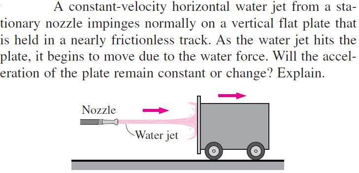
64 The momentum equation is commonly used to calculate the forces (usually on support systems or connectors) induced by the flow. 64

65 Steady flow Special Cases Mass flow rate across an inlet or outlet Momentum flow rate across a uniform inlet or outlet: In a typical engineering problem, the control volume may contain many inlets and outlets; at each inlet or outlet we define the mass flow rate and the average velocity. 65
66 Examples of inlets or outlets in which the uniform flow approximation is reasonable: (a) the well-rounded entrance to a pipe, (b) the entrance to a wind tunnel test section, and (c) a slice through a free water jet in air. 66
67 Momentum-Flux Correction Factor, The velocity across most inlets and outlets is not uniform. The control surface integral of Eq may be converted into algebraic form using a dimensionless correction factor, called the momentum-flux correction factor. (13-13) is always greater than or equal to 1. is close to 1 for turbulent flow and not very close to 1 for fully developed laminar flow. 67

68 Steady Flow The net force acting on the control volume during steady flow is equal to the difference between the rates of outgoing and incoming momentum flows. The net force acting on the control volume during steady flow is equal to the difference between the outgoing and the incoming momentum fluxes. 68


69 Steady Flow with One Inlet and One Outlet One inlet and one outlet Along x- coordinate A control volume with only one inlet and one outlet. The determination by vector addition of the reaction force on the support caused by a change of direction of water. 69

70 Flow with No External Forces In the absence of external forces, the rate of change of the momentum of a control volume is equal to the difference between the rates of incoming and outgoing momentum flow rates. The thrust needed to lift the space shuttle is generated by the rocket engines as a result of momentum change of the fuel as it is accelerated from about zero to an exit speed of about 2000 m/s after combustion. 70
71 Example:
72 Example:
73 Example:
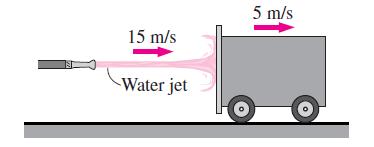
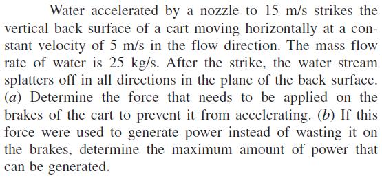
74 Example:
75 REVIEW OF ROTATIONAL MOTION AND ANGULAR MOMENTUM Rotational motion: A motion during which all points in the body move in circles about the axis of rotation. Rotational motion is described with angular quantities such as the angular distance, angular velocity, and angular acceleration. Angular velocity: The angular distance traveled per unit time. Angular acceleration: The rate of change of angular velocity. The relations between angular distance, angular velocity, and linear velocity V. 75
76 Newton s second law requires that there must be a force acting in the tangential direction to cause angular acceleration. The strength of the rotating effect, called the moment or torque, is proportional to the magnitude of the force and its distance from the axis of rotation. The perpendicular distance from the axis of rotation to the line of action of the force is called the moment arm, and the torque M acting on a point mass m at a normal distance r from the axis of rotation is expressed as Torque I is the moment of inertia of the body about the axis of rotation, which is a measure of the inertia of a body against rotation. Unlike mass, the rotational inertia of a body also depends on the distribution of the mass of the body with respect to the axis of rotation. Analogy between corresponding linear and angular quantities. 76

77 Angular momentum Angular momentum equation Angular velocity versus rpm Angular momentum of point mass m rotating at angular velocity at distance r from the axis of rotation. The relations between angular velocity, rpm, and the power transmitted through a shaft. 77
78 Rotational kinetic energy Shaft power During rotational motion, the direction of velocity changes even when its magnitude remains constant. Velocity is a vector quantity, and thus a change in direction constitutes a change in velocity with time, and thus acceleration. This is called centripetal acceleration. Centripetal acceleration is directed toward the axis of rotation (opposite direction of radial acceleration), and thus the radial acceleration is negative. Centripetal acceleration is the result of a force acting on an element of the body toward the axis of rotation, known as the centripetal force, whose magnitude is F r = mv 2 /r. Tangential and radial accelerations are perpendicular to each other, and the total linear acceleration is determined by their vector sum: 78

79 THE ANGULAR MOMENTUM EQUATION Many engineering problems involve the moment of the linear momentum of flow streams, and the rotational effects caused by them. Such problems are best analyzed by the angular momentum equation, also called the moment of momentum equation. An important class of fluid devices, called turbomachines, which include centrifugal pumps, turbines, and fans, is analyzed by the angular momentum equation. A force whose line of action passes through point O produces zero moment about point O. The determination of the direction of the moment by the right-hand rule. 79

80 Moment of momentum Moment of momentum (system) Angular momentum equation for a system Rate of change of moment of momentum 80
81 Special Cases During steady flow, the amount of angular momentum within the control volume remains constant, and thus the time rate of change of angular momentum of the contents of the control volume is zero. An approximate form of the angular momentum equation in terms of average properties at inlets and outlets: The net torque acting on the control volume during steady flow is equal to the difference between the outgoing and incoming angular momentum flow rates. scalar form of angular momentum equation 81
82 Radial-Flow Devices Radial-flow devices: Many rotary-flow devices such as centrifugal pumps and fans involve flow in the radial direction normal to the axis of rotation. Axial-flow devices are easily analyzed using the linear momentum equation. Radial-flow devices involve large changes in angular momentum of the fluid and are best analyzed with the help of the angular momentum equation. Side and frontal views of a typical centrifugal pump. 82

83 The conservation of mass equation for steady incompressible flow angular momentum equation Euler s turbine formula When An annular control volume that encloses the impeller section of a centrifugal pump. 83
84 Example:
85 Example:
CHAPTER 5 MASS AND ENERGY ANALYSIS OF CONTROL VOLUMES
 Thermodynamics: An Engineering Approach 8th Edition in SI Units Yunus A. Çengel, Michael A. Boles McGraw-Hill, 2015 CHAPTER 5 MASS AND ENERGY ANALYSIS OF CONTROL VOLUMES Lecture slides by Dr. Fawzi Elfghi
Chapter 4 ENERGY ANALYSIS OF CLOSED SYSTEMS
 Thermodynamics: An Engineering Approach Seventh Edition in SI Units Yunus A. Cengel, Michael A. Boles McGraw-Hill, 2011 Chapter 4 ENERGY ANALYSIS OF CLOSED SYSTEMS Copyright The McGraw-Hill Companies,
Chapter Four fluid flow mass, energy, Bernoulli and momentum
 4-1Conservation of Mass Principle Consider a control volume of arbitrary shape, as shown in Fig (4-1). Figure (4-1): the differential control volume and differential control volume (Total mass entering
ENERGY ANALYSIS OF CLOSED SYSTEMS
 Thermodynamics: An Engineering Approach Seventh Edition in SI Units Yunus A. Cengel, Michael A. Boles McGraw-Hill, 2011 Chapter 4 ENERGY ANALYSIS OF CLOSED SYSTEMS Mehmet Kanoglu University of Gaziantep
Chapter 5: Mass, Bernoulli, and Energy Equations
 Chapter 5: Mass, Bernoulli, and Energy Equations Introduction This chapter deals with 3 equations commonly used in fluid mechanics The mass equation is an expression of the conservation of mass principle.
Therefore, the control volume in this case can be treated as a solid body, with a net force or thrust of. bm # V
 When the mass m of the control volume remains nearly constant, the first term of the Eq. 6 8 simply becomes mass times acceleration since 39 CHAPTER 6 d(mv ) CV m dv CV CV (ma ) CV Therefore, the control
Objectives. Conservation of mass principle: Mass Equation The Bernoulli equation Conservation of energy principle: Energy equation
 Objectives Conservation of mass principle: Mass Equation The Bernoulli equation Conservation of energy principle: Energy equation Conservation of Mass Conservation of Mass Mass, like energy, is a conserved
MASS, MOMENTUM, AND ENERGY EQUATIONS
 MASS, MOMENTUM, AND ENERGY EQUATIONS This chapter deals with four equations commonly used in fluid mechanics: the mass, Bernoulli, Momentum and energy equations. The mass equation is an expression of the
Chapter 5: The First Law of Thermodynamics: Closed Systems
 Chapter 5: The First Law of Thermodynamics: Closed Systems The first law of thermodynamics can be simply stated as follows: during an interaction between a system and its surroundings, the amount of energy
Chapter 5: Mass, Bernoulli, and
 and Energy Equations 5-1 Introduction 5-2 Conservation of Mass 5-3 Mechanical Energy 5-4 General Energy Equation 5-5 Energy Analysis of Steady Flows 5-6 The Bernoulli Equation 5-1 Introduction This chapter
The First Law of Thermodynamics. By: Yidnekachew Messele
 The First Law of Thermodynamics By: Yidnekachew Messele It is the law that relates the various forms of energies for system of different types. It is simply the expression of the conservation of energy
first law of ThermodyNamics
 first law of ThermodyNamics First law of thermodynamics - Principle of conservation of energy - Energy can be neither created nor destroyed Basic statement When any closed system is taken through a cycle,
Lesson 6 Review of fundamentals: Fluid flow
 Lesson 6 Review of fundamentals: Fluid flow The specific objective of this lesson is to conduct a brief review of the fundamentals of fluid flow and present: A general equation for conservation of mass
Chapter 5. Mass and Energy Analysis of Control Volumes. by Asst. Prof. Dr.Woranee Paengjuntuek and Asst. Prof. Dr.Worarattana Pattaraprakorn
 Chapter 5 Mass and Energy Analysis of Control Volumes by Asst. Prof. Dr.Woranee Paengjuntuek and Asst. Prof. Dr.Worarattana Pattaraprakorn Reference: Cengel, Yunus A. and Michael A. Boles, Thermodynamics:
Chapter 5. Mass and Energy Analysis of Control Volumes
 Chapter 5 Mass and Energy Analysis of Control Volumes Conservation Principles for Control volumes The conservation of mass and the conservation of energy principles for open systems (or control volumes)
vector H. If O is the point about which moments are desired, the angular moment about O is given:
 The angular momentum A control volume analysis can be applied to the angular momentum, by letting B equal to angularmomentum vector H. If O is the point about which moments are desired, the angular moment
Chapter 7 The Energy Equation
 Chapter 7 The Energy Equation 7.1 Energy, Work, and Power When matter has energy, the matter can be used to do work. A fluid can have several forms of energy. For example a fluid jet has kinetic energy,
THE FIRST LAW APPLIED TO STEADY FLOW PROCESSES
 Chapter 10 THE FIRST LAW APPLIED TO STEADY FLOW PROCESSES It is not the sun to overtake the moon, nor doth the night outstrip theday.theyfloateachinanorbit. The Holy Qur-ān In many engineering applications,
Introduction to Chemical Engineering Thermodynamics. Chapter 7. KFUPM Housam Binous CHE 303
 Introduction to Chemical Engineering Thermodynamics Chapter 7 1 Thermodynamics of flow is based on mass, energy and entropy balances Fluid mechanics encompasses the above balances and conservation of momentum
COURSE NUMBER: ME 321 Fluid Mechanics I 3 credit hour. Basic Equations in fluid Dynamics
 COURSE NUMBER: ME 321 Fluid Mechanics I 3 credit hour Basic Equations in fluid Dynamics Course teacher Dr. M. Mahbubur Razzaque Professor Department of Mechanical Engineering BUET 1 Description of Fluid
Chapter 2: Basic Governing Equations
 -1 Reynolds Transport Theorem (RTT) - Continuity Equation -3 The Linear Momentum Equation -4 The First Law of Thermodynamics -5 General Equation in Conservative Form -6 General Equation in Non-Conservative
Week 8. Steady Flow Engineering Devices. GENESYS Laboratory
 Week 8. Steady Flow Engineering Devices Objectives 1. Solve energy balance problems for common steady-flow devices such as nozzles, compressors, turbines, throttling valves, mixers, heaters, and heat exchangers
Thermodynamics: An Engineering Approach Seventh Edition Yunus A. Cengel, Michael A. Boles McGraw-Hill, Chapter 7 ENTROPY
 Thermodynamics: An Engineering Approach Seventh Edition Yunus A. Cengel, Michael A. Boles McGraw-Hill, 2011 Chapter 7 ENTROPY Copyright The McGraw-Hill Companies, Inc. Permission required for reproduction
Chapter 7. Entropy. by Asst.Prof. Dr.Woranee Paengjuntuek and Asst. Prof. Dr.Worarattana Pattaraprakorn
 Chapter 7 Entropy by Asst.Prof. Dr.Woranee Paengjuntuek and Asst. Prof. Dr.Worarattana Pattaraprakorn Reference: Cengel, Yunus A. and Michael A. Boles, Thermodynamics: An Engineering Approach, 5th ed.,
Thermodynamics ENGR360-MEP112 LECTURE 7
 Thermodynamics ENGR360-MEP11 LECTURE 7 Thermodynamics ENGR360/MEP11 Objectives: 1. Conservation of mass principle.. Conservation of energy principle applied to control volumes (first law of thermodynamics).
4 Mechanics of Fluids (I)
") 1. The x and y components of velocity for a two-dimensional flow are u = 3.0 ft/s and v = 9.0x ft/s where x is in feet. Determine the equation for the streamlines and graph representative streamlines in
1. The x and y components of velocity for a two-dimensional flow are u = 3.0 ft/s and v = 9.0x ft/s where x is in feet. Determine the equation for the streamlines and graph representative streamlines in
where = rate of change of total energy of the system, = rate of heat added to the system, = rate of work done by the system
 The Energy Equation for Control Volumes Recall, the First Law of Thermodynamics: where = rate of change of total energy of the system, = rate of heat added to the system, = rate of work done by the system
ENT 254: Applied Thermodynamics
 ENT 54: Applied Thermodynamics Mr. Azizul bin Mohamad Mechanical Engineering Program School of Mechatronic Engineering Universiti Malaysia Perlis (UniMAP) azizul@unimap.edu.my 019-4747351 04-9798679 Chapter
Applied Fluid Mechanics
 Applied Fluid Mechanics 1. The Nature of Fluid and the Study of Fluid Mechanics 2. Viscosity of Fluid 3. Pressure Measurement 4. Forces Due to Static Fluid 5. Buoyancy and Stability 6. Flow of Fluid and
Chapter 17. For the most part, we have limited our consideration so COMPRESSIBLE FLOW. Objectives
 Chapter 17 COMPRESSIBLE FLOW For the most part, we have limited our consideration so far to flows for which density variations and thus compressibility effects are negligible. In this chapter we lift this
ENTROPY. Chapter 7. Mehmet Kanoglu. Thermodynamics: An Engineering Approach, 6 th Edition. Yunus A. Cengel, Michael A. Boles.
 Thermodynamics: An Engineering Approach, 6 th Edition Yunus A. Cengel, Michael A. Boles McGraw-Hill, 2008 Chapter 7 ENTROPY Mehmet Kanoglu Copyright The McGraw-Hill Companies, Inc. Permission required
Thermodynamics: An Engineering Approach Seventh Edition in SI Units Yunus A. Cengel, Michael A. Boles McGraw-Hill, 2011.
 Thermodynamics: An Engineering Approach Seventh Edition in SI Units Yunus A. Cengel, Michael A. Boles McGraw-Hill, 2011 Chapter 7 ENTROPY Mehmet Kanoglu University of Gaziantep Copyright The McGraw-Hill
BME-A PREVIOUS YEAR QUESTIONS
 BME-A PREVIOUS YEAR QUESTIONS CREDITS CHANGE ACCHA HAI TEAM UNIT-1 Introduction: Introduction to Thermodynamics, Concepts of systems, control volume, state, properties, equilibrium, quasi-static process,
5/6/ :41 PM. Chapter 6. Using Entropy. Dr. Mohammad Abuhaiba, PE
 Chapter 6 Using Entropy 1 2 Chapter Objective Means are introduced for analyzing systems from the 2 nd law perspective as they undergo processes that are not necessarily cycles. Objective: introduce entropy
Angular momentum equation
 Angular momentum equation For angular momentum equation, B =H O the angular momentum vector about point O which moments are desired. Where β is The Reynolds transport equation can be written as follows:
Introduction to Turbomachinery
 1. Coordinate System Introduction to Turbomachinery Since there are stationary and rotating blades in turbomachines, they tend to form a cylindrical form, represented in three directions; 1. Axial 2. Radial
Thermodynamics I Spring 1432/1433H (2011/2012H) Saturday, Wednesday 8:00am - 10:00am & Monday 8:00am - 9:00am MEP 261 Class ZA
 Saturday, Wednesday 8:00am - 10:00am & Monday 8:00am - 9:00am MEP 261 Class ZA") Thermodynamics I Spring 1432/1433H (2011/2012H) Saturday, Wednesday 8:00am - 10:00am & Monday 8:00am - 9:00am MEP 261 Class ZA Dr. Walid A. Aissa Associate Professor, Mech. Engg. Dept. Faculty of Engineering
Thermodynamics I Spring 1432/1433H (2011/2012H) Saturday, Wednesday 8:00am - 10:00am & Monday 8:00am - 9:00am MEP 261 Class ZA Dr. Walid A. Aissa Associate Professor, Mech. Engg. Dept. Faculty of Engineering
I. (20%) Answer the following True (T) or False (F). If false, explain why for full credit.
 Answer the following True (T) or False (F). If false, explain why for full credit.") I. (20%) Answer the following True (T) or False (F). If false, explain why for full credit. Both the Kelvin and Fahrenheit scales are absolute temperature scales. Specific volume, v, is an intensive property,
I. (20%) Answer the following True (T) or False (F). If false, explain why for full credit. Both the Kelvin and Fahrenheit scales are absolute temperature scales. Specific volume, v, is an intensive property,
Answers to questions in each section should be tied together and handed in separately.
 EGT0 ENGINEERING TRIPOS PART IA Wednesday 4 June 014 9 to 1 Paper 1 MECHANICAL ENGINEERING Answer all questions. The approximate number of marks allocated to each part of a question is indicated in the
Conservation of Momentum using Control Volumes
 Conservation of Momentum using Control Volumes Conservation of Linear Momentum Recall the conservation of linear momentum law for a system: In order to convert this for use in a control volume, use RTT
FE Fluids Review March 23, 2012 Steve Burian (Civil & Environmental Engineering)
") Topic: Fluid Properties 1. If 6 m 3 of oil weighs 47 kn, calculate its specific weight, density, and specific gravity. 2. 10.0 L of an incompressible liquid exert a force of 20 N at the earth s surface.
Topic: Fluid Properties 1. If 6 m 3 of oil weighs 47 kn, calculate its specific weight, density, and specific gravity. 2. 10.0 L of an incompressible liquid exert a force of 20 N at the earth s surface.
Chapter Two. Basic Thermodynamics, Fluid Mechanics: Definitions of Efficiency. Laith Batarseh
 Chapter Two Basic Thermodynamics, Fluid Mechanics: Definitions of Efficiency Laith Batarseh The equation of continuity Most analyses in this book are limited to one-dimensional steady flows where the velocity
CHAPTER 7 ENTROPY. Copyright Hany A. Al-Ansary and S. I. Abdel-Khalik (2014) 1
 1") CHAPTER 7 ENTROPY S. I. Abdel-Khalik (2014) 1 ENTROPY The Clausius Inequality The Clausius inequality states that for for all cycles, reversible or irreversible, engines or refrigerators: For internally-reversible
CHAPTER 7 ENTROPY S. I. Abdel-Khalik (2014) 1 ENTROPY The Clausius Inequality The Clausius inequality states that for for all cycles, reversible or irreversible, engines or refrigerators: For internally-reversible
First Law of Thermodynamics
 CH2303 Chemical Engineering Thermodynamics I Unit II First Law of Thermodynamics Dr. M. Subramanian 07-July-2011 Associate Professor Department of Chemical Engineering Sri Sivasubramaniya Nadar College
Dishwasher. Heater. Homework Solutions ME Thermodynamics I Spring HW-1 (25 points)
") HW-1 (25 points) (a) Given: 1 for writing given, find, EFD, etc., Schematic of a household piping system Find: Identify system and location on the system boundary where the system interacts with the environment
HW-1 (25 points) (a) Given: 1 for writing given, find, EFD, etc., Schematic of a household piping system Find: Identify system and location on the system boundary where the system interacts with the environment
ESO201A: Thermodynamics
 ESO201A: Thermodynamics First Semester 2015-2016 Mid-Semester Examination Instructor: Sameer Khandekar Time: 120 mins Marks: 250 Solve sub-parts of a question serially. Question #1 (60 marks): One kmol
3.8 The First Law of Thermodynamics and the Energy Equation
 CEE 3310 Control Volume Analysis, Sep 30, 2011 65 Review Conservation of angular momentum 1-D form ( r F )ext = [ˆ ] ( r v)d + ( r v) out ṁ out ( r v) in ṁ in t CV 3.8 The First Law of Thermodynamics and
Two mark questions and answers UNIT I BASIC CONCEPT AND FIRST LAW SVCET
 Two mark questions and answers UNIT I BASIC CONCEPT AND FIRST LAW 1. What do you understand by pure substance? A pure substance is defined as one that is homogeneous and invariable in chemical composition
Fluid Mechanics. du dy
 FLUID MECHANICS Technical English - I 1 th week Fluid Mechanics FLUID STATICS FLUID DYNAMICS Fluid Statics or Hydrostatics is the study of fluids at rest. The main equation required for this is Newton's
2.The lines that are tangent to the velocity vectors throughout the flow field are called steady flow lines. True or False A. True B.
 CHAPTER 03 1. Write Newton's second law of motion. YOUR ANSWER: F = ma 2.The lines that are tangent to the velocity vectors throughout the flow field are called steady flow lines. True or False 3.Streamwise
Chapter (6) Energy Equation and Its Applications
 Energy Equation and Its Applications") Chapter (6) Energy Equation and Its Applications Bernoulli Equation Bernoulli equation is one of the most useful equations in fluid mechanics and hydraulics. And it s a statement of the principle of conservation
Chapter (6) Energy Equation and Its Applications Bernoulli Equation Bernoulli equation is one of the most useful equations in fluid mechanics and hydraulics. And it s a statement of the principle of conservation
Where F1 is the force and dl1 is the infinitesimal displacement, but F1 = p1a1
 In order to force the fluid to flow across the boundary of the system against a pressure p1, work is done on the boundary of the system. The amount of work done is dw = - F1.dl1, Where F1 is the force
Chapter 6. Using Entropy
 Chapter 6 Using Entropy Learning Outcomes Demonstrate understanding of key concepts related to entropy and the second law... including entropy transfer, entropy production, and the increase in entropy
Chapter 7. Dr Ali Jawarneh. Department of Mechanical Engineering Hashemite University
 Chapter 7 ENTROPY Dr Ali Jawarneh Department of Mechanical Engineering Hashemite University Objectives Apply the second law of thermodynamics to processes. Define a new property called entropy to quantify
 CHAPTER INTRODUCTION AND BASIC PRINCIPLES. (Tutorial). Determine if the following properties of the system are intensive or extensive properties: Property Intensive Extensive Volume Density Conductivity
First Law of Thermodynamics Closed Systems
 First Law of Thermodynamics Closed Systems Content The First Law of Thermodynamics Energy Balance Energy Change of a System Mechanisms of Energy Transfer First Law of Thermodynamics in Closed Systems Moving
The Bernoulli Equation
 The Bernoulli Equation The most used and the most abused equation in fluid mechanics. Newton s Second Law: F = ma In general, most real flows are 3-D, unsteady (x, y, z, t; r,θ, z, t; etc) Let consider
Turbomachinery. Hasan Ozcan Assistant Professor. Mechanical Engineering Department Faculty of Engineering Karabuk University
 Turbomachinery Hasan Ozcan Assistant Professor Mechanical Engineering Department Faculty of Engineering Karabuk University Introduction Hasan Ozcan, Ph.D, (Assistant Professor) B.Sc :Erciyes University,
IX. COMPRESSIBLE FLOW. ρ = P
 IX. COMPRESSIBLE FLOW Compressible flow is the study of fluids flowing at speeds comparable to the local speed of sound. This occurs when fluid speeds are about 30% or more of the local acoustic velocity.
Thermodynamics INTRODUCTION AND BASIC CONCEPTS. Copyright The McGraw-Hill Companies, Inc. Permission required for reproduction or display.
 Thermodynamics INTRODUCTION AND BASIC CONCEPTS Copyright The McGraw-Hill Companies, Inc. Permission required for reproduction or display. THERMODYNAMICS AND ENERGY Thermodynamics: The science of energy.
UNIT I Basic concepts and Work & Heat Transfer
 SIDDHARTH GROUP OF INSTITUTIONS :: PUTTUR Siddharth Nagar, Narayanavanam Road 517583 QUESTION BANK (DESCRIPTIVE) Subject with Code: Engineering Thermodynamics (16ME307) Year & Sem: II-B. Tech & II-Sem
1 st Law Analysis of Control Volume (open system) Chapter 6
 Chapter 6") 1 st Law Analysis of Control Volume (open system) Chapter 6 In chapter 5, we did 1st law analysis for a control mass (closed system). In this chapter the analysis of the 1st law will be on a control volume
1 st Law Analysis of Control Volume (open system) Chapter 6 In chapter 5, we did 1st law analysis for a control mass (closed system). In this chapter the analysis of the 1st law will be on a control volume
Thermodynamics I Spring 1432/1433H (2011/2012H) Saturday, Wednesday 8:00am - 10:00am & Monday 8:00am - 9:00am MEP 261 Class ZA
 Saturday, Wednesday 8:00am - 10:00am & Monday 8:00am - 9:00am MEP 261 Class ZA") Thermodynamics I Spring 1432/1433H (2011/2012H) Saturday, Wednesday 8:00am - 10:00am & Monday 8:00am - 9:00am MEP 261 Class ZA Dr. Walid A. Aissa Associate Professor, Mech. Engg. Dept. Faculty of Engineering
Thermodynamics I Spring 1432/1433H (2011/2012H) Saturday, Wednesday 8:00am - 10:00am & Monday 8:00am - 9:00am MEP 261 Class ZA Dr. Walid A. Aissa Associate Professor, Mech. Engg. Dept. Faculty of Engineering
Lecture 1: Kinematics, ideal mechanical systems and Bernoulli s equation
 Lecture 1: Kinematics, ideal mechanical systems and Bernoulli s equation Should be able to: Understand some terms used in flow visualization and kinematics Understand Lagrangian and Eulerian frames of
Aerodynamics. Basic Aerodynamics. Continuity equation (mass conserved) Some thermodynamics. Energy equation (energy conserved)
 Some thermodynamics. Energy equation (energy conserved)") Flow with no friction (inviscid) Aerodynamics Basic Aerodynamics Continuity equation (mass conserved) Flow with friction (viscous) Momentum equation (F = ma) 1. Euler s equation 2. Bernoulli s equation
Flow with no friction (inviscid) Aerodynamics Basic Aerodynamics Continuity equation (mass conserved) Flow with friction (viscous) Momentum equation (F = ma) 1. Euler s equation 2. Bernoulli s equation
ME3560 Tentative Schedule Fall 2018
 ME3560 Tentative Schedule Fall 2018 Week Number 1 Wednesday 8/29/2018 1 Date Lecture Topics Covered Introduction to course, syllabus and class policies. Math Review. Differentiation. Prior to Lecture Read
ME3560 Tentative Schedule Spring 2019
 ME3560 Tentative Schedule Spring 2019 Week Number Date Lecture Topics Covered Prior to Lecture Read Section Assignment Prep Problems for Prep Probs. Must be Solved by 1 Monday 1/7/2019 1 Introduction to
Engineering Thermodynamics. Chapter 1. Introductory Concepts and Definition
 1.1 Introduction Chapter 1 Introductory Concepts and Definition Thermodynamics may be defined as follows : Thermodynamics is an axiomatic science which deals with the relations among heat, work and properties
PART 0 PRELUDE: REVIEW OF "UNIFIED ENGINEERING THERMODYNAMICS"
 PART 0 PRELUDE: REVIEW OF "UNIFIED ENGINEERING THERMODYNAMICS" PART 0 - PRELUDE: REVIEW OF UNIFIED ENGINEERING THERMODYNAMICS [IAW pp -, 3-41 (see IAW for detailed SB&VW references); VN Chapter 1] 01 What
AEROSPACE ENGINEERING DEPARTMENT. Second Year - Second Term ( ) Fluid Mechanics & Gas Dynamics
 Fluid Mechanics & Gas Dynamics") AEROSPACE ENGINEERING DEPARTMENT Second Year - Second Term (2008-2009) Fluid Mechanics & Gas Dynamics Similitude,Dimensional Analysis &Modeling (1) [7.2R*] Some common variables in fluid mechanics include:
AEROSPACE ENGINEERING DEPARTMENT Second Year - Second Term (2008-2009) Fluid Mechanics & Gas Dynamics Similitude,Dimensional Analysis &Modeling (1) [7.2R*] Some common variables in fluid mechanics include:
ME332 FLUID MECHANICS LABORATORY (PART II)
") ME332 FLUID MECHANICS LABORATORY (PART II) Mihir Sen Department of Aerospace and Mechanical Engineering University of Notre Dame Notre Dame, IN 46556 Version: April 2, 2002 Contents Unit 5: Momentum transfer
ME332 FLUID MECHANICS LABORATORY (PART II) Mihir Sen Department of Aerospace and Mechanical Engineering University of Notre Dame Notre Dame, IN 46556 Version: April 2, 2002 Contents Unit 5: Momentum transfer
Please welcome for any correction or misprint in the entire manuscript and your valuable suggestions kindly mail us
 Problems of Practices Of Fluid Mechanics Compressible Fluid Flow Prepared By Brij Bhooshan Asst. Professor B. S. A. College of Engg. And Technology Mathura, Uttar Pradesh, (India) Supported By: Purvi Bhooshan
Introduction. In general, gases are highly compressible and liquids have a very low compressibility. COMPRESSIBLE FLOW
 COMRESSIBLE FLOW COMRESSIBLE FLOW Introduction he compressibility of a fluid is, basically, a measure of the change in density that will be produced in the fluid by a specific change in pressure and temperature.
Chapter 4 DYNAMICS OF FLUID FLOW
 Faculty Of Engineering at Shobra nd Year Civil - 016 Chapter 4 DYNAMICS OF FLUID FLOW 4-1 Types of Energy 4- Euler s Equation 4-3 Bernoulli s Equation 4-4 Total Energy Line (TEL) and Hydraulic Grade Line
Chapter 3 Bernoulli Equation
 1 Bernoulli Equation 3.1 Flow Patterns: Streamlines, Pathlines, Streaklines 1) A streamline, is a line that is everywhere tangent to the velocity vector at a given instant. Examples of streamlines around
FE Exam Fluids Review October 23, Important Concepts
 FE Exam Fluids Review October 3, 013 mportant Concepts Density, specific volume, specific weight, specific gravity (Water 1000 kg/m^3, Air 1. kg/m^3) Meaning & Symbols? Stress, Pressure, Viscosity; Meaning
(Refer Slide Time: 4:41)
") Fluid Machines. Professor Sankar Kumar Som. Department Of Mechanical Engineering. Indian Institute Of Technology Kharagpur. Lecture-30. Basic Principle and Energy Transfer in Centrifugal Compressor Part
Fluid Machines. Professor Sankar Kumar Som. Department Of Mechanical Engineering. Indian Institute Of Technology Kharagpur. Lecture-30. Basic Principle and Energy Transfer in Centrifugal Compressor Part
ME Thermodynamics I
 Homework - Week 01 HW-01 (25 points) Given: 5 Schematic of the solar cell/solar panel Find: 5 Identify the system and the heat/work interactions associated with it. Show the direction of the interactions.
R13 SET - 1 '' ''' '' ' '''' Code No RT21033
 SET - 1 II B. Tech I Semester Supplementary Examinations, June - 2015 THERMODYNAMICS (Com. to ME, AE, AME) Time: 3 hours Max. Marks: 70 Note: 1. Question Paper consists of two parts (Part-A and Part-B)
CEE 3310 Control Volume Analysis, Oct. 10, = dt. sys
 CEE 3310 Control Volume Analysis, Oct. 10, 2018 77 3.16 Review First Law of Thermodynamics ( ) de = dt Q Ẇ sys Sign convention: Work done by the surroundings on the system < 0, example, a pump! Work done
Engineering Thermodynamics
 David Ng Summer 2017 Contents 1 July 5, 2017 3 1.1 Thermodynamics................................ 3 2 July 7, 2017 3 2.1 Properties.................................... 3 3 July 10, 2017 4 3.1 Systems.....................................
equation 4.1 INTRODUCTION
 4 The momentum equation 4.1 INTRODUCTION It is often important to determine the force produced on a solid body by fluid flowing steadily over or through it. For example, there is the force exerted on a
Thermodynamics II. Week 9
 hermodynamics II Week 9 Example Oxygen gas in a piston cylinder at 300K, 00 kpa with volume o. m 3 is compressed in a reversible adiabatic process to a final temperature of 700K. Find the final pressure
Part A: 1 pts each, 10 pts total, no partial credit.
 Part A: 1 pts each, 10 pts total, no partial credit. 1) (Correct: 1 pt/ Wrong: -3 pts). The sum of static, dynamic, and hydrostatic pressures is constant when flow is steady, irrotational, incompressible,
Non-Newtonian fluids is the fluids in which shear stress is not directly proportional to deformation rate, such as toothpaste,
 CHAPTER1: Basic Definitions, Zeroth, First, and Second Laws of Thermodynamics 1.1. Definitions What does thermodynamic mean? It is a Greeks word which means a motion of the heat. Water is a liquid substance
As Per New GTU Syllabus
 As Per New GTU Syllabus Prepared by: Mr. Bhavin J. Vegada (M.Tech Thermal Engg.) Mr. Ketan C. Agola (M.Tech. Thermal Engg.) Darshan Institute of Engineering &Technology BRIEF CONTENTS Chapter No. Title
CEE 3310 Control Volume Analysis, Oct. 7, D Steady State Head Form of the Energy Equation P. P 2g + z h f + h p h s.
 CEE 3310 Control Volume Analysis, Oct. 7, 2015 81 3.21 Review 1-D Steady State Head Form of the Energy Equation ( ) ( ) 2g + z = 2g + z h f + h p h s out where h f is the friction head loss (which combines
Chapter 7. Entropy: A Measure of Disorder
 Chapter 7 Entropy: A Measure of Disorder Entropy and the Clausius Inequality The second law of thermodynamics leads to the definition of a new property called entropy, a quantitative measure of microscopic
CHAPTER 3 BASIC EQUATIONS IN FLUID MECHANICS NOOR ALIZA AHMAD
 CHAPTER 3 BASIC EQUATIONS IN FLUID MECHANICS 1 INTRODUCTION Flow often referred as an ideal fluid. We presume that such a fluid has no viscosity. However, this is an idealized situation that does not exist.
Applied Thermodynamics for Marine Systems Prof. P. K. Das Department of Mechanical Engineering Indian Institute of Technology, Kharagpur
 Applied Thermodynamics for Marine Systems Prof. P. K. Das Department of Mechanical Engineering Indian Institute of Technology, Kharagpur Lecture No - 03 First Law of Thermodynamics (Open System) Good afternoon,
ME Thermodynamics I. Lecture Notes and Example Problems
 ME 227.3 Thermodynamics I Lecture Notes and Example Problems James D. Bugg September 2018 Department of Mechanical Engineering Introduction Part I: Lecture Notes This part contains handout versions of
Basic Fluid Mechanics
 Basic Fluid Mechanics Chapter 5: Application of Bernoulli Equation 4/16/2018 C5: Application of Bernoulli Equation 1 5.1 Introduction In this chapter we will show that the equation of motion of a particle
Modeling and Analysis of Dynamic Systems
 Modeling and Analysis of Dynamic Systems Dr. Guillaume Ducard Fall 2017 Institute for Dynamic Systems and Control ETH Zurich, Switzerland G. Ducard c 1 / 34 Outline 1 Lecture 7: Recall on Thermodynamics
Detailed Outline, M E 320 Fluid Flow, Spring Semester 2015
 Detailed Outline, M E 320 Fluid Flow, Spring Semester 2015 I. Introduction (Chapters 1 and 2) A. What is Fluid Mechanics? 1. What is a fluid? 2. What is mechanics? B. Classification of Fluid Flows 1. Viscous
Unified Quiz: Thermodynamics
 Unified Quiz: Thermodynamics October 14, 2005 Calculators allowed. No books or notes allowed. A list of equations is provided. Put your ID number on each page of the exam. Read all questions carefully.
Chapter 6: Momentum Analysis
 6-1 Introduction 6-2Newton s Law and Conservation of Momentum 6-3 Choosing a Control Volume 6-4 Forces Acting on a Control Volume 6-5Linear Momentum Equation 6-6 Angular Momentum 6-7 The Second Law of
Chapter 1: Basic Definitions, Terminologies and Concepts
 Chapter : Basic Definitions, Terminologies and Concepts ---------------------------------------. UThermodynamics:U It is a basic science that deals with: -. Energy transformation from one form to another..
Chapter 6: Momentum Analysis of Flow Systems
 Chapter 6: Momentum Analysis of Flow Systems Introduction Fluid flow problems can be analyzed using one of three basic approaches: differential, experimental, and integral (or control volume). In Chap.
ME 2322 Thermodynamics I PRE-LECTURE Lesson 23 Complete the items below Name:
 Lesson 23 1. (10 pt) Write the equation for the thermal efficiency of a Carnot heat engine below: T η = T 1 L H 2. (10 pt) Can the thermal efficiency of an actual engine ever exceed that of an equivalent
THERMODYNAMICS, FLUID AND PLANT PROCESSES. The tutorials are drawn from other subjects so the solutions are identified by the appropriate tutorial.
 THERMODYNAMICS, FLUID AND PLANT PROCESSES The tutorials are drawn from other subjects so the solutions are identified by the appropriate tutorial. THERMODYNAMICS TUTORIAL 2 THERMODYNAMIC PRINCIPLES SAE