Elastic shear buckling capacity of the longitudinally stiffened flat panels
|
|
|
- Suzan Garrison
- 5 years ago
- Views:
Transcription
1 Analysis and Design of Marine Structures Guedes Soares & Shenoi (Eds) 015 Taylor & Francis Group, London, ISBN Elastic shear buckling capacity of the longitudinally stiffened flat panels S. Kitarovic, J. Andric & K. iric Faculty of Mechanical Engineering and Naval Architecture, University of Zagreb, Zagreb, Croatia ABSTRACT: Various feasible approaches to the increase of the flat plate elastic shear buckling capacity are investigated. Based on derived theoretical envelopes of the considered approaches, stiffening parallel to the longer plate edges is identified as the most effective approach to the considered problem. An accompanying analytical formulation is approximated in a form convenient for utilization in structural analysis and design of the plated structures. All derived conclusions and proposed formulations are based on results of the numerous rationally designed numerical simulations utilizing the finite element method. 1 INTRODUCTION 1.1 General remarks During the ship exploitation, an imposed vertical shear loading is predominantly resisted by the vertically oriented parts of the hull girder structure (e.g. sides and longitudinal bulkheads). ronounced shear loading of the significant intensity can induce occurrence of the shear buckling and eventual shear collapse of the structural elements loaded in shear when acting shear load surpasses their ultimate shear load capacity. ossibility of incidence for such a hazardous event becomes even more significant if relevant structural elements have been damaged previously (e.g. by collision) and consequently suffered a notable decrease in the load capacity with respect to the undamaged condition. In this context, consideration of the shear load capacity of the hull girder structural elements can represent a relevant aspect and an important structural adequacy criterion in analysis and design of the ship structures. Occurrence of the shear buckling does not represent the ultimate limit state of the plating loaded in edge shear. Its ultimate limit state is eventually reached by a total depletion of the complete load capacity margin of the diagonal tension fields, see Bleich & Ramsey (195), i.e. by the complete plastification (yielding) of the plate material loaded in tension. Unfortunately, exact assessment of the (ultimate) shear load capacity of the hull girder plating necessitates detailed description of the still unresolved and very complex interaction of all relevant parameters of influence. This disables complete and accurate theoretical description of the shear collapse phenomena. Consequently, virtually all of the existing ultimate shear strength formulations are of the semi-empirical nature and are predominantly formulated by means of the regression analyses based on various results obtained by experimental investigations and/or numerical simulations. Concise description of the various existing formulations of the plate ultimate shear load capacity can be found in Zhang et al. (008). Since the most of the contemporary ultimate shear load capacity formulations are based on the correction of the calculated elastic shear buckling critical stress, within the framework of this paper various possible approaches to the elastic shear buckling inhibition are discussed. The most obvious one among them is to maximize the rotational restraint along the plate edges, resulting ultimately with the clamped edge restraints. However, the actual edge restraint imposed at the plate edge joints varies between the two extreme cases (simply supported and clamped). Only the worst (simply supported) case, which provides the highest margin for the increase of the plate elastic shear load capacity, is considered further in this paper. 1. Elastic shear buckling of the simply supported flat plates An isotropic, flat plate of length L, breadth B and thickness t, loaded along the all four boundaries (edges) by pure and uniformly distributed in-plane edge shear stress is considered (see Fig. 1). If the geometrical and material characteristics of the considered plate are such that elastic shear buckling occurs at the critical intensity of the imposed edge shear loading, the corresponding deflected state of the unstable equilibrium can be described by the St. Venants equation, see Timoshenko & Gere (1985), (given for the pure edge shear case), which is valid if the lateral displacements are small with respect to t: 463
 where τ cr represents the plate elastic shear buckling stress, D denotes the plate flexural rigidity, while w denotes the out-of-plane or lateral (in")
2 Figure 1. Elastic shear buckling of the simply supported (un)stiffened plate. 4 4 w w + 4 x x y + 4 w = τ crt w 4 y D x y (1) where τ cr represents the plate elastic shear buckling stress, D denotes the plate flexural rigidity, while w denotes the out-of-plane or lateral (in direction of the z-axis) displacement. Although the exact solution of (1) is not known, an approximate solution can be derived using the stationary potential energy principle and a Ritz method (lateral displacements expressed in terms of the appropriate coordinate functions which satisfy considered boundary conditions): τ cr π D = k = k Bt π E t ν B 1( 1 ) () E and ν denote Young s modulus of elasticity and oisson s ratio, respectively, while k denotes the non-dimensional coefficient dependant only on L/B: k = L L + for B 1 B L L 534. for B + 4 < 1 B (3) Although formulation of k given by (3) is widely accepted in the contemporary structural analysis and design practice, it actually represents the parabolic approximation of the more accurate values of k calculated previously by various authors, see Bleich & Ramsey (195). 1.3 late shear buckling capacity magnification It should be noted that for a given plate material, τ cr depends solely on the plate geometrical characteristics L/B and t/b, according to (). This suggests that τ cr can be increased by two distinct approaches: by decrease in the L/B value and/or by increase in the t/b value. Decrease in the L/B value can be accomplished by subdivision of the plate onto smaller and equal parts by addition of the equidistantly placed transverse (parallel with the y-axis) stiffeners, whereby t/b ratio remains unchanged. On the other hand, increase in the t/b value can be accomplished by the increase of the plate thickness and/or by subdivision of the plate onto smaller and equal parts by addition of the equidistantly placed longitudinal (parallel with x-axis) stiffeners. Yet, since the aspect ratio of the obtained plate subdivisions a/b (where a denotes length of the plating between stiffeners parallel to the stiffener orientation, while b denotes breadth of the plating between stiffeners perpendicular to the stiffener orientation, see Figure 1) is thereby increased, it seems, at the first glance, that the positive effect of this approach is somewhat attenuated. Since various possible approaches to the plate elastic shear buckling capacity magnification are identified, it would be useful to determine the most effective one among them, i.e. to identify the most gainful approach which would enable maximum increase in critical shear stress. In this respect, it is important to emphasize that the most gainful effects of the plate stiffening can be exploited only if the critical value of the acting shear load induces imminent occurrence of the local shear buckling (shear buckling of the plating between stiffeners), i.e. that occurrence of the global shear buckling (shear buckling of the whole stiffened plate) is successfully disabled. In another words, this will be accomplished only if the plating between stiffeners can be considered as a set of an independent, simply supported plates loaded in edge shear. Ability to comply with this requirement depends on the flexural rigidity of stiffener(s) employed, which must be sufficient to enable successful resistance of the stiffener(s) to the predominant vertical bending load imposed by the buckling half waves during their spread along the stiffened plate. 464
3 Based on this paradigm, originally introduced by Timoshenko, see Bleich & Ramsey (195), Figure illustrates the obtained maximum relative increases in the critical shear stress attainable by the longitudinal and/or transverse (equidistant) stiffening of the plate for various L/B ratios and number of added stiffeners N S, where τ cr S denotes elastic shear buckling stress of the stiffened plate. It is important to emphasize that the curves depicted by Figure are valid for an arbitrary plate thickness, i.e. t/b ratio. Generally, it can be noted that the transverse stiffening represents better approach for the L/B < 1 cases, while longitudinal stiffening is preferable for the L/B > 1 cases. Furthermore, it should be noted that inverse pairs of the L/B values (e.g. L/B = and L/B = 0.5) are characterized by the identical results. This is due to the inherent irrelevance of the acting edge shear load direction, which consequently induces overall symmetry of the obtained results with respect to the L/B = 1 case, which is characterized by the lowest attainable relative critical shear stress increase. For this case identical results are obtained by longitudinal and transverse stiffening, since both of those approaches result in an identical stiffened plate layout. Hence, based on the above considerations, it can be generally concluded that the plate stiffening with stiffeners parallel to the longer side of the initial plate always represents a more gainful approach, irrespective whether L/B < 1 or L/B > Existing formulations of the stiffened plate elastic shear buckling capacity The first formulation regarding the considered problem was proposed by Timoshenko, see Bleich & Ramsey (195), for a stiffened plate having one or Figure. Maximum increase in the elastic shear buckling capacity attainable by the plate stiffening. two transverse stiffeners. This pioneering theoretical work based on the energy approach was extended subsequently by many authors and a more extensive overviews of the research work regarding this problem can be found in Bleich & Ramsey (195), Hughes (1988) and Alinia (005). All of the existing formulations are based on the previously mentioned Timoshenko s paradigm and it is interesting to note that virtually all of them are derived considering stiffening parallel to the shorter side of the initial plate only, although the discussion given in Section 1.3 clearly suggests that an alternative stiffening approach is much more effective. Modeling of the considered problem.1 Design of numerical experiments In order to validate the above given theoretical considerations, as well as to provide the basis for the general formulation proposed in Section 4, close to three hundred rationally designed numerical experiments are performed employing the Finite Element Method (FEM) simulations for generation of the results for various (un)stiffened plate configurations. All considered variants are characterized by the same (isotropic) material (E = 06 Ga; ν = 0.3) and B = 300 mm. Furthermore, due to the previously mentioned symmetry of the considered problem, only variants characterized by L/B 1 are considered. All other geometrical properties fall within the (relatively wide) range determined to cover the characteristic dimensions of the ship hull girder s flat single side plating between wing and bilge tanks of the existing and variously sized bulk carriers. Unstiffened plates are analyzed in order to investigate the correspondence of the results obtained by utilization of () and by numerical simulations. For this purpose five different L/B values (1; ; 3; 6; 1) and five different t/b values (0.005; ; 0.005; ; ) are considered, resulting in a total of 5 numerical experiments. Furthermore, in order to verify the theoretically obtained envelopes (see Figure ) and their independence of t, analyses of the plates stiffened by one, two or three longitudinal or transverse stiffeners (of the infinite flexural rigidity) are performed for three different L/B values (1; ; 3) and three different t/b values (0.005; 0.005; ), resulting in a total of 54 numerical experiments. Finally, in order to generate the experimental basis for the proposed formulation, analyses of the plates stiffened by longitudinal stiffeners (of the finite flexural rigidity) are performed. In 465
4 this respect, previously mentioned Timoshenko s paradigm (which neglects torsional rigidity of stiffeners) enables arbitrary selection of the shape and scantlings of the employed stiffener profile, since only the stiffeners moment of inertia I S is relevant for its flexural rigidity. Among an infinite number of the possible stiffener profile variants characterized by the same particular I S, a flangeless (flatbar) stiffener profile is selected for the further consideration. This choice is due to the irrelevance of the higher section modulus (offered by the flanged profiles) for the considered problem and since the flatbar stiffener offers the highest possible I S = t w h w3 /1 for the particular stiffener cross sectional area, or in another words, provides attainment of the particular flexural rigidity with the least amount of the stiffener material. Furthermore, since the results (τ cr S ) are suggestively independent of t, the same value (16 mm) is used for the stiffener web thickness t w and t of all variants considered within this experimental batch and various stiffener flexural rigidities considered are attained only by variation of the stiffener web height h w. Thereby, 13 different stiffener flexural rigidities are considered for each of the three different L/B values (1; ; 3) and three different N S values (1,, 3), resulting in a total of 117 numerical experiments. Throughout this paper, particular variant can be easily identified according to the assigned designation (e.g. AR1-T16-S1 L designates the plate with L/B = 1, t = t w = 16 mm and one longitudinal stiffener).. Numerical simulations All executed numerical simulations are based on utilization of the FEM analysis of the discretized models of the considered (un)stiffened plate variants, whose bifurcation buckling load is determined by the eigenvalue analysis, as implemented within the employed FEMA/NX Nastran (010) computer program. Lanczos method is used for the eigenvalue extraction and the lowest (positive) eigenvalue is accepted as the quantitative representative of the relevant buckling mode..3 Discretized model All considered models are discretized by the twodimensional, quadrilateral, isoparametric finite elements with four nodes (CQUAD4) and six degrees of freedom (DoFs) at each node. The imposed edge shear load is applied by means of the properly oriented nodal forces along the plate edges, as illustrated by Figure 1. Their magnitude is determined according to the expressions given in Figure 1, where F n L B and F n denote the absolute values of the nodal forces applied along the L and B edges, respectively. F L and corner F B corner denote the absolute values of the components (parallel to the L and B edges, respectively) of the resultant nodal force applied at the plate corners (nodes coincident with the points 1,, 3 and 4 ), while A L and A B denote the cross sectional areas of the L and B edges, respectively. F L and F B denote the absolute values of the total forces applied along the L and B edges, respectively, while n L and n B denote the total number of nodes along the L and B edges, respectively. Indicated expressions for F nl, F nb, F L and corner FB corner are derived in order to ensure the proper in-plane deformation of the corner finite elements, i.e. to ensure that straightness of the plate edges is fully retained in the deformed state. In this respect, it can be observed that F nl /F L and/or F corner nb /F B corner ratios should be equal to 4. In order to properly simulate deformation of the simply supported (un)stiffened plate models, nodal DoF constraints are applied as described by Table 1, where 0 and 1 denote constrained and unconstrained nodal DoF, respectively. For the numerical simulations of the simply supported plates reinforced by the stiffeners of the infinite flexural rigidity, in addition to the constraints given by Table 1, vertical nodal displacements are constrained (T z = 0) for all nodes along the plate to stiffener joint (line segment 6 7 in Figure 1). In order to rationally determine an appropriate finite element mesh density for discretization of all considered FEM models, an extensive mesh convergence study is performed. For this purpose, two extreme values of L/B (1; 1) and t/b (0.005; ) are considered for both unstiffened and stiffened (by three stiffeners of the infinite flexural rigidity) plate variants, since the sensitivity of the results obtained for those cases should envelope the sensitivities characteristic for all other (un)stiffened plate variants considered by the above given plan of numerical experiments. For each of those eight (un)stiffened plate variants, ten different mesh density variants are considered, with 1, 4, 36, 48, 60, 7, 84, 96, 108 and 10 elements along the B edges. Corresponding number of elements along the L edges is unambiguously determined so as to keep the finite element aspect ratio equal to Table 1. Applied constraints of nodal DoFs. Node location Nodal DoFs: (see Figure 1) T x T y T z R x R y R z 1 ; 3 ; 3 4 ; 4 1 ; All other plate nodes
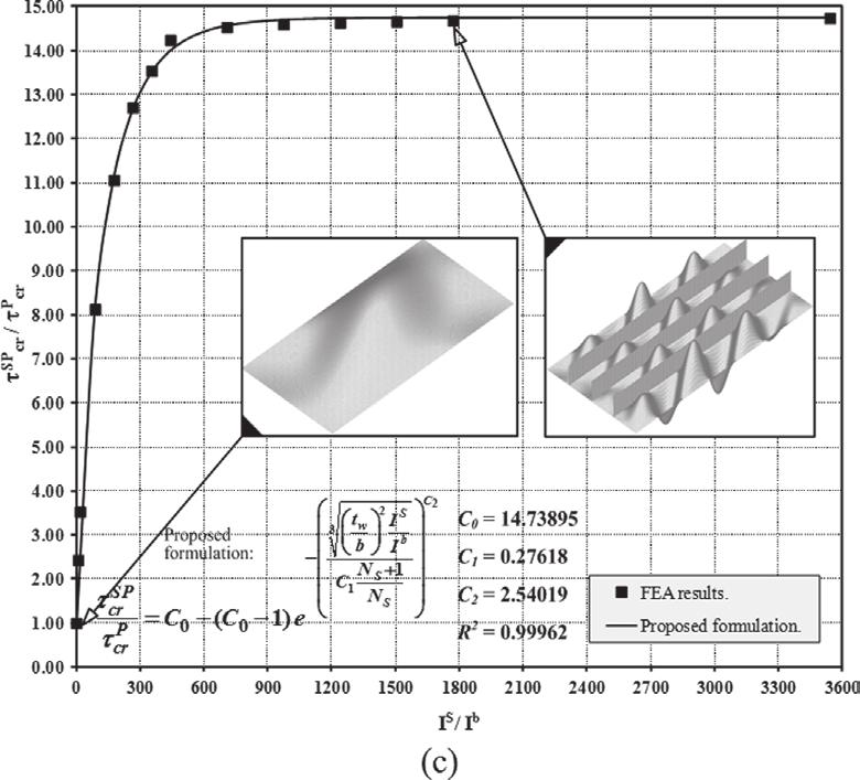
5 1 for each mesh density variant. This results in a total of 80 additional numerical experiments considered within the framework of the mesh convergence study. The results of the mesh convergence study are concisely given by Figure 3. It can be noted that the mesh density characterized by 96 elements along the B edges gives a considerable relative reduction (>35%) of the total number of DoFs N DoF, while always providing a very small relative difference (<0.15%) of the obtained results (τ cr ), all with respect to the finest mesh density. Consequently, this mesh density is used for all subsequently performed numerical simulations. 3 RESULTS Figure 4 illustrates the results obtained for the considered unstiffened plates. An excellent agreement of the results obtained by () and numerical simulations can be observed. Although an approximated relationship between those results is proposed (see Fig. 4), only a negligible error is introduced by its disregard (τ cr-fea = τ cr-analytical ). The results of the numerical simulations obtained for plates stiffened by the infinitely rigid stiffeners are given in Figure. It should be observed that the results obtained for various t/b ratios are practically coincident. Furthermore, a very good agreement with the proposed theoretical envelopes can be observed. Superimposed display of all results obtained by the numerical simulations performed for all considered plate variants reinforced by stiffeners with various (finite) flexural rigidity is given in τ cr S - A S /A space, represented by Figure 5, where A S denotes the area of the transverse cross section of the longitudinally stiffened plate, while A denotes the area of the transverse cross section of the initial (unstiffened) plate. A more detailed display of the same results is given in τ cr S - I S /I b space, represented by Figures 6 8, where I b = bt 3 /1 represents the moment of inertia of the plating between stiffeners. Figure 6 additionally indicates the results obtained by three existing formulations of the considered problem, applicable only for L/B = 1 cases among the considered ones. Figure 5 also displays the results obtained by the plate thickness increase approach in τ cr E - A E /A space, where τ cr E denotes the elastic shear buckling stress of the plate characterized by the (increased) equivalent thickness t E (see Fig. 5), while A E denotes the area of its transverse cross section. 4 elastic shear load capacity of the longitudinally stiffened, simply supported, flat plates made of isotropic material Figure 3. Results of the mesh convergence study. Results of the numerical simulations performed for nine considered plate variants reinforced by stiffeners of various (finite) flexural rigidity are used for formulation of the approximate description (surrogate model) of the considered problem. For this purpose a regression analysis based on utilization of the least squares method is performed, whereby coefficient of determination (R ) is used as a quantitative measure of the accomplished approximation quality. The crucial choice regarding the appropriate form of the approximation function is based on the similar S-shaped layout of the results obtained 467
6 Figure 4. Unstiffened plate results, obtained by FEM analyses and by utilization of (). Figure 5. Results obtained for longitudinal stiffening and for increase of the plate thickness. 468

 S")


7 Figure 6. Results for AR1-T16: a) S1 L; b) S L; c) S3 L. Figure 7. Results for AR-T16: a) S1 L; b) S L; c) S3 L. 469

8 for every considered stiffened plate variant, which can be observed in Figure 5. Although various sigmoid functions were considered for approximation of the results in τ cr S A S /A space, the best approximate fit is accomplished by utilization of the adjusted cumulative distribution function of the Weibull distribution: τ S cr A S τ cr A C 1 C0 1 = C0 S C A A 1 exp C ; C > 0 (4) C 0, C 1 and C represent the non-dimensional coefficients, whose specific values characterize every particular stiffened plate variant considered. C 0 actually represents the highest τ cr S value obtained (by numerical experiments) for each stiffened plate variant, while the corresponding values of C 1 and C are determined numerically, using a Levenberg-Marquardt algorithm within the framework of the least squares method. Calculated values of the C 0, C 1, C and R, along with the corresponding plots of (4) in τ cr S I S /I b space, are given in Figures 6 8 for each of the nine considered stiffened plate variants, respectively. In order to derive the general formulation valid for an arbitrary L/B ratio within the considered range (1 L/B 3), all values of the C 0, C 1 and C determined for the nine considered stiffened plate variants are used. Considering the number of the available results and their scatter (see Fig. 9), the second degree polynomial is selected as an adequate function for determination of the exact fit: Figure 8. Results for AR3-T16: a) S1 L; b) S L; c) S3 L. Figure 9. Graphical display of C 0, C 1 and C coefficients. 470
9 Table. Calculated values of, and ) coefficients. N S = 1 ( j = 1) N S = ( j = ) N S = 3 ( j = 3) ) ) C 0 (i = C 1 (i = 1) C (i = ) a a Ci = ij + ij ij b + ( κ ) 0 ( κ ) 1 ( κ ) b i = 0,..., ; j = 1,..., 3 (5) where, and ) represent the (nondimensional) polynomial coefficients valid for the respective stiffened plate variant. Calculated values which determine curves illustrated by Figure 9, are given in Table. It should be noted that the validity of the proposed formulation is limited on stiffening parallel to the longer side of the plate, with N S = 1,, 3, while both 1 L/B 3 and L/B 1 ranges are covered due to the previously mentioned symmetry of the considered problem (with respect to L/B = 1). However, within the L/B < 1 range, L and a should be interchanged with B and b, respectively. 5 CONCLUSIONS Accuracy of the commonly and widely accepted formulation of the elastic shear buckling capacity of the unstiffened flat plates, given by (), is verified by the results obtained by numerical simulations (see Fig. 4). Furthermore, proposed theoretical envelopes and their independence of t, derived using Timoshenko s paradigm and (), are also verified by the obtained results of the numerical simulations (see Fig. ). This confirms the proposition that longitudinal stiffening for L/B > 1 cases and transverse stiffening for L/B < 1 cases, i.e. stiffening parallel to the longer side of the plate, always represents a more effective approach to the considered problem than the stiffening parallel to the shorter side of the plate (considered by all existing formulations). Moreover, comparison of the results obtained for all considered plates reinforced by stiffeners of various (finite) flexural rigidity (see Figs. 5 8), with respect to the results obtained for the plate thickness increase approach (see Fig. 5), suggests that the proposed stiffen- ing approach always represents a more effective approach to the considered problem. Hence, it can be unconditionally concluded that the proposed stiffening approach represents the most rational course for the elastic shear load capacity magnification of the simply supported plates. Furthermore, based on the results of the rationally designed and properly configured numerical simulations, an approximate formulation for this stiffening approach is proposed (valid for L/B 3 and N S = 1,, 3). In this respect, a considerably high accuracy level of the proposed formulation, as well as its convenient mathematical nature, can contribute to its recognition as an useful additional tool in the process of analysis and/ or design of the ship structures. ACKNOWLEDGEMENTS Thanks are due to our student Antonio Mikulic for realization of the portion of the structural models and numerical simulations performed within the scope of work presented by this paper. This work has been supported in part by Croatian Science Foundation under the project References Alinia, M.M A study into optimization of stiffeners in plates subjected to shear loading. Thin-Walled Structures 43: Bleich, F. & Ramsey, L.B Buckling strength of metal structures. New York: McGraw-Hill. FEMA/NX Nastran Software Documentation. Siemens roduct Lifecycle Management Software. Hughes, O.F Ship structural design: A rationally-based, computer-aided optimization approach. Jersey City: The Society of Naval Architects and Marine Engineers. Timoshenko, S.. & Gere, J.M Theory of elastic stability. New York: McGraw-Hill. Zhang, S., Kumar,. & Rutherford, S.E Ultimate shear strength of plates and stiffened panels. Ships and Offshore Structures 3():
Stability of Simply Supported Square Plate with Concentric Cutout
 International OPEN ACCESS Journal Of Modern Engineering Research (IJMER) Stability of Simply Supported Square Plate with Concentric Cutout Jayashankarbabu B. S. 1, Dr. Karisiddappa 1 (Civil Engineering
FLEXIBILITY METHOD FOR INDETERMINATE FRAMES
 UNIT - I FLEXIBILITY METHOD FOR INDETERMINATE FRAMES 1. What is meant by indeterminate structures? Structures that do not satisfy the conditions of equilibrium are called indeterminate structure. These
Ultimate shear strength of FPSO stiffened panels after supply vessel collision
 Ultimate shear strength of FPSO stiffened panels after supply vessel collision Nicolau Antonio dos Santos Rizzo PETROBRAS Rio de Janeiro Brazil Marcelo Caire SINTEF do Brasil Rio de Janeiro Brazil Carlos
An Evaluation and Comparison of Models for Maximum Deflection of Stiffened Plates Using Finite Element Analysis
 Marine Technology, Vol. 44, No. 4, October 2007, pp. 212 225 An Evaluation and Comparison of Models for Maximum Deflection of Stiffened Plates Using Finite Element Analysis Lior Banai 1 and Omri Pedatzur
Iraq Ref. & Air. Cond. Dept/ Technical College / Kirkuk
 International Journal of Scientific & Engineering Research, Volume 6, Issue 4, April-015 1678 Study the Increasing of the Cantilever Plate Stiffness by Using s Jawdat Ali Yakoob Iesam Jondi Hasan Ass.
ULTIMATE STRENGTH OF SQUARE PLATE WITH RECTANGULAR OPENING UNDER AXIAL COMPRESSION
 Journal of Naval Architecture and Marine Engineering June, 2007 http://jname.8m.net ULTIMATE STRENGTH OF SQUARE PLATE WITH RECTANGULAR OPENING UNDER AXIAL COMPRESSION M. Suneel Kumar 1*, P. Alagusundaramoorthy
AN IMPROVED NUMERICAL MODEL FOR CALCULATING SHIP HULL FRAME TRANSVERSAL STRUCTURE
 COMPUTATIONAL MECHANICS New Trends and Applications E. Oñate and S. R. Idelsohn (Eds.) CIMNE, Barcelona, Spain 1998 AN IMPROVED NUMERICAL MODEL FOR CALCULATING SHIP HULL FRAME TRANSVERSAL STRUCTURE Oscar
Experimental Study and Numerical Simulation on Steel Plate Girders With Deep Section
 6 th International Conference on Advances in Experimental Structural Engineering 11 th International Workshop on Advanced Smart Materials and Smart Structures Technology August 1-2, 2015, University of
CHAPTER 5 PROPOSED WARPING CONSTANT
 122 CHAPTER 5 PROPOSED WARPING CONSTANT 5.1 INTRODUCTION Generally, lateral torsional buckling is a major design aspect of flexure members composed of thin-walled sections. When a thin walled section is
LINEAR AND NONLINEAR BUCKLING ANALYSIS OF STIFFENED CYLINDRICAL SUBMARINE HULL
 LINEAR AND NONLINEAR BUCKLING ANALYSIS OF STIFFENED CYLINDRICAL SUBMARINE HULL SREELATHA P.R * M.Tech. Student, Computer Aided Structural Engineering, M A College of Engineering, Kothamangalam 686 666,
An Increase in Elastic Buckling Strength of Plate Girder by the Influence of Transverse Stiffeners
 GRD Journals- Global Research and Development Journal for Engineering Volume 2 Issue 6 May 2017 ISSN: 2455-5703 An Increase in Elastic Buckling Strength of Plate Girder by the Influence of Transverse Stiffeners
Flexural-Torsional Buckling of General Cold-Formed Steel Columns with Unequal Unbraced Lengths
 Proceedings of the Annual Stability Conference Structural Stability Research Council San Antonio, Texas, March 21-24, 2017 Flexural-Torsional Buckling of General Cold-Formed Steel Columns with Unequal
Workshop 8. Lateral Buckling
 Workshop 8 Lateral Buckling cross section A transversely loaded member that is bent about its major axis may buckle sideways if its compression flange is not laterally supported. The reason buckling occurs
PLAT DAN CANGKANG (TKS 4219)
") PLAT DAN CANGKANG (TKS 4219) SESI I: PLATES Dr.Eng. Achfas Zacoeb Dept. of Civil Engineering Brawijaya University INTRODUCTION Plates are straight, plane, two-dimensional structural components of which
PLAT DAN CANGKANG (TKS 4219) SESI I: PLATES Dr.Eng. Achfas Zacoeb Dept. of Civil Engineering Brawijaya University INTRODUCTION Plates are straight, plane, two-dimensional structural components of which
DYNAMIC RESPONSE OF THIN-WALLED GIRDERS SUBJECTED TO COMBINED LOAD
 DYNAMIC RESPONSE OF THIN-WALLED GIRDERS SUBJECTED TO COMBINED LOAD P. WŁUKA, M. URBANIAK, T. KUBIAK Department of Strength of Materials, Lodz University of Technology, Stefanowskiego 1/15, 90-924 Łódź,
Bending of Simply Supported Isotropic and Composite Laminate Plates
 Bending of Simply Supported Isotropic and Composite Laminate Plates Ernesto Gutierrez-Miravete 1 Isotropic Plates Consider simply a supported rectangular plate of isotropic material (length a, width b,
Lecture 15 Strain and stress in beams
 Spring, 2019 ME 323 Mechanics of Materials Lecture 15 Strain and stress in beams Reading assignment: 6.1 6.2 News: Instructor: Prof. Marcial Gonzalez Last modified: 1/6/19 9:42:38 PM Beam theory (@ ME
Design of Steel Structures Prof. S.R.Satish Kumar and Prof. A.R.Santha Kumar. Local buckling is an extremely important facet of cold formed steel
 5.3 Local buckling Local buckling is an extremely important facet of cold formed steel sections on account of the fact that the very thin elements used will invariably buckle before yielding. Thinner the
ARTICLE IN PRESS. Thin-Walled Structures
 Thin-Walled Structures 47 (009) 4 Contents lists available at ScienceDirect Thin-Walled Structures journal homepage: www.elsevier.com/locate/tws Y-stiffened panel multi-objective optimization using genetic
MODULE C: COMPRESSION MEMBERS
 MODULE C: COMPRESSION MEMBERS This module of CIE 428 covers the following subjects Column theory Column design per AISC Effective length Torsional and flexural-torsional buckling Built-up members READING:
Longitudinal strength standard
 (1989) (Rev. 1 199) (Rev. Nov. 001) Longitudinal strength standard.1 Application This requirement applies only to steel ships of length 90 m and greater in unrestricted service. For ships having one or
INFLUENCE OF FLANGE STIFFNESS ON DUCTILITY BEHAVIOUR OF PLATE GIRDER
 International Journal of Civil Structural 6 Environmental And Infrastructure Engineering Research Vol.1, Issue.1 (2011) 1-15 TJPRC Pvt. Ltd.,. INFLUENCE OF FLANGE STIFFNESS ON DUCTILITY BEHAVIOUR OF PLATE
RULES PUBLICATION NO. 17/P ZONE STRENGTH ANALYSIS OF HULL STRUCTURE OF ROLL ON/ROLL OFF SHIP
 RULES PUBLICATION NO. 17/P ZONE STRENGTH ANALYSIS OF HULL STRUCTURE OF ROLL ON/ROLL OFF SHIP 1995 Publications P (Additional Rule Requirements), issued by Polski Rejestr Statków, complete or extend the
Nonlinear bending analysis of laminated composite stiffened plates
 Nonlinear bending analysis of laminated composite stiffened plates * S.N.Patel 1) 1) Dept. of Civi Engineering, BITS Pilani, Pilani Campus, Pilani-333031, (Raj), India 1) shuvendu@pilani.bits-pilani.ac.in
Structural Dynamics Lecture Eleven: Dynamic Response of MDOF Systems: (Chapter 11) By: H. Ahmadian
 By: H. Ahmadian") Structural Dynamics Lecture Eleven: Dynamic Response of MDOF Systems: (Chapter 11) By: H. Ahmadian ahmadian@iust.ac.ir Dynamic Response of MDOF Systems: Mode-Superposition Method Mode-Superposition Method:
Structural Dynamics Lecture Eleven: Dynamic Response of MDOF Systems: (Chapter 11) By: H. Ahmadian ahmadian@iust.ac.ir Dynamic Response of MDOF Systems: Mode-Superposition Method Mode-Superposition Method:
COMPUTATIONAL MODELING APPLIED TO THE STUDY OF THERMAL BUCKLING OF COLUMNS
 COMPUTATIONAL MODELING APPLIED TO THE STUDY OF THERMAL BUCKLING OF COLUMNS R. da S. Michaello a, D. Helbig b, L. A. O. Rocha b, M. de V. Real c, E. D. dos Santos c, and L. A. Isoldi c a Universidade Federal
Bilinear Quadrilateral (Q4): CQUAD4 in GENESIS
: CQUAD4 in GENESIS") Bilinear Quadrilateral (Q4): CQUAD4 in GENESIS The Q4 element has four nodes and eight nodal dof. The shape can be any quadrilateral; we ll concentrate on a rectangle now. The displacement field in terms
Bilinear Quadrilateral (Q4): CQUAD4 in GENESIS The Q4 element has four nodes and eight nodal dof. The shape can be any quadrilateral; we ll concentrate on a rectangle now. The displacement field in terms
UNIT- I Thin plate theory, Structural Instability:
 UNIT- I Thin plate theory, Structural Instability: Analysis of thin rectangular plates subject to bending, twisting, distributed transverse load, combined bending and in-plane loading Thin plates having
PLATE GIRDERS II. Load. Web plate Welds A Longitudinal elevation. Fig. 1 A typical Plate Girder
 16 PLATE GIRDERS II 1.0 INTRODUCTION This chapter describes the current practice for the design of plate girders adopting meaningful simplifications of the equations derived in the chapter on Plate Girders
CHAPTER THREE SYMMETRIC BENDING OF CIRCLE PLATES
 CHAPTER THREE SYMMETRIC BENDING OF CIRCLE PLATES * Governing equations in beam and plate bending ** Solution by superposition 1.1 From Beam Bending to Plate Bending 1.2 Governing Equations For Symmetric
Optimum Height of Plate Stiffener under Pressure Effect
 The st Regional Conference of Eng. Sci. NUCEJ Spatial ISSUE vol., No.3, 8 pp 459-468 Optimum Height of Plate Stiffener under Pressure Effect Mazin Victor Yousif M.Sc Production Engineering University of
Part D: Frames and Plates
 Part D: Frames and Plates Plane Frames and Thin Plates A Beam with General Boundary Conditions The Stiffness Method Thin Plates Initial Imperfections The Ritz and Finite Element Approaches A Beam with
CONSIDERATIONS ON DIMENSIONING OF GARAGE DECKS
 CONSIDERATIONS ON DIMENSIONING OF GARAGE DECKS Antonio Campanile, Masino Mandarino, Vincenzo Piscopo Department of Naval Engineering, The University Federico II, Naples SUMMAR This work deals with the
Nonlinear Buckling Prediction in ANSYS. August 2009
 Nonlinear Buckling Prediction in ANSYS August 2009 Buckling Overview Prediction of buckling of engineering structures is a challenging problem for several reasons: A real structure contains imperfections
Mechanics of Materials Primer
 Mechanics of Materials rimer Notation: A = area (net = with holes, bearing = in contact, etc...) b = total width of material at a horizontal section d = diameter of a hole D = symbol for diameter E = modulus
FINITE ELEMENT ANALYSIS OF TAPERED COMPOSITE PLATE GIRDER WITH A NON-LINEAR VARYING WEB DEPTH
 Journal of Engineering Science and Technology Vol. 12, No. 11 (2017) 2839-2854 School of Engineering, Taylor s University FINITE ELEMENT ANALYSIS OF TAPERED COMPOSITE PLATE GIRDER WITH A NON-LINEAR VARYING
PLEASURE VESSEL VIBRATION AND NOISE FINITE ELEMENT ANALYSIS
 PLEASURE VESSEL VIBRATION AND NOISE FINITE ELEMENT ANALYSIS 1 Macchiavello, Sergio *, 2 Tonelli, Angelo 1 D Appolonia S.p.A., Italy, 2 Rina Services S.p.A., Italy KEYWORDS pleasure vessel, vibration analysis,
INTERNATIONAL JOURNAL OF APPLIED ENGINEERING RESEARCH, DINDIGUL Volume 2, No 1, 2011
 Interlaminar failure analysis of FRP cross ply laminate with elliptical cutout Venkateswara Rao.S 1, Sd. Abdul Kalam 1, Srilakshmi.S 1, Bala Krishna Murthy.V 2 1 Mechanical Engineering Department, P. V.
Simulation of Geometrical Cross-Section for Practical Purposes
 Simulation of Geometrical Cross-Section for Practical Purposes Bhasker R.S. 1, Prasad R. K. 2, Kumar V. 3, Prasad P. 4 123 Department of Mechanical Engineering, R.D. Engineering College, Ghaziabad, UP,
ANALYSIS OF THE INTERACTIVE BUCKLING IN STIFFENED PLATES USING A SEMI-ANALYTICAL METHOD
 EUROSTEEL 2014, September 10-12, 2014, Naples, Italy ANALYSIS OF THE INTERACTIVE BUCKLING IN STIFFENED PLATES USING A SEMI-ANALYTICAL METHOD Pedro Salvado Ferreira a, Francisco Virtuoso b a Polytechnic
Analysis of Shear Lag Effect of Box Beam under Dead Load
 Analysis of Shear Lag Effect of Box Beam under Dead Load Qi Wang 1, a, Hongsheng Qiu 2, b 1 School of transportation, Wuhan University of Technology, 430063, Wuhan Hubei China 2 School of transportation,
PURE BENDING. If a simply supported beam carries two point loads of 10 kn as shown in the following figure, pure bending occurs at segment BC.
 BENDING STRESS The effect of a bending moment applied to a cross-section of a beam is to induce a state of stress across that section. These stresses are known as bending stresses and they act normally
Aalto University School of Engineering
 Aalto University School of Engineering Kul-4.4 Ship Structural Design (P) ecture 6 - Response of Web-frames, Girders and Grillages Kul-4.4 Ship Structures Response ecture 5: Tertiary Response: Bending
Sabah Shawkat Cabinet of Structural Engineering Walls carrying vertical loads should be designed as columns. Basically walls are designed in
 Sabah Shawkat Cabinet of Structural Engineering 17 3.6 Shear walls Walls carrying vertical loads should be designed as columns. Basically walls are designed in the same manner as columns, but there are
A Parametric Study on Lateral Torsional Buckling of European IPN and IPE Cantilevers H. Ozbasaran
 Vol:8, No:7, 214 A Parametric Study on Lateral Torsional Buckling of European IPN and IPE Cantilevers H. Ozbasaran Abstract IPN and IPE sections, which are commonly used European I shapes, are widely used
CHAPTER 14 BUCKLING ANALYSIS OF 1D AND 2D STRUCTURES
 CHAPTER 14 BUCKLING ANALYSIS OF 1D AND 2D STRUCTURES 14.1 GENERAL REMARKS In structures where dominant loading is usually static, the most common cause of the collapse is a buckling failure. Buckling may
CHAPTER 5. Beam Theory
 CHPTER 5. Beam Theory SangJoon Shin School of Mechanical and erospace Engineering Seoul National University ctive eroelasticity and Rotorcraft Lab. 5. The Euler-Bernoulli assumptions One of its dimensions
Effect of Mass Matrix Formulation Schemes on Dynamics of Structures
 Effect of Mass Matrix Formulation Schemes on Dynamics of Structures Swapan Kumar Nandi Tata Consultancy Services GEDC, 185 LR, Chennai 600086, India Sudeep Bosu Tata Consultancy Services GEDC, 185 LR,
INFLUENCE OF WEB THICKNESS REDUCTION IN THE SHEAR RESISTANCE OF NON-PRISMATIC TAPERED PLATE GIRDERS
 INFLUENCE OF WEB THICKNESS REDUCTION IN THE SHEAR RESISTANCE OF NON-PRISMATIC TAPERED PLATE GIRDERS Paulo J. S. Cruz 1, Lúcio Lourenço 1, Hélder Quintela 2 and Manuel F. Santos 2 1 Department of Civil
Ultimate uniaxial compressive strength of stiffened panel with opening under lateral pressure
 csnak, 015 Int. J. Nav. Archit. Ocean Eng. (015) 7:399~408 http://dx.doi.org/10.1515/ijnaoe-015-008 pissn: 09-678, eissn: 09-6790 Ultimate uniaxial compressive strength of stiffened panel with opening
The 10 th international Energy Conference (IEC 2014)
") Ultimate Limit State Assessments of Steel Plates for Spar-Type Floating Offshore Wind Turbines 1. Sajad Rahmdel 1) 2. Hyerin Kwon 2) 3. Seonghun Park 3) 1), 2), 3) School of Mechanical Engineering, Pusan
Ultimate Limit State Assessments of Steel Plates for Spar-Type Floating Offshore Wind Turbines 1. Sajad Rahmdel 1) 2. Hyerin Kwon 2) 3. Seonghun Park 3) 1), 2), 3) School of Mechanical Engineering, Pusan
2. (a) Explain different types of wing structures. (b) Explain the advantages and disadvantages of different materials used for aircraft
 Explain different types of wing structures. (b) Explain the advantages and disadvantages of different materials used for aircraft") Code No: 07A62102 R07 Set No. 2 III B.Tech II Semester Regular/Supplementary Examinations,May 2010 Aerospace Vehicle Structures -II Aeronautical Engineering Time: 3 hours Max Marks: 80 Answer any FIVE
Code No: 07A62102 R07 Set No. 2 III B.Tech II Semester Regular/Supplementary Examinations,May 2010 Aerospace Vehicle Structures -II Aeronautical Engineering Time: 3 hours Max Marks: 80 Answer any FIVE
Accordingly, the nominal section strength [resistance] for initiation of yielding is calculated by using Equation C-C3.1.
![Accordingly, the nominal section strength [resistance] for initiation of yielding is calculated by using Equation C-C3.1.](/thumbs/89/98617066.jpg "Accordingly, the nominal section strength [resistance] for initiation of yielding is calculated by using Equation C-C3.1.") C3 Flexural Members C3.1 Bending The nominal flexural strength [moment resistance], Mn, shall be the smallest of the values calculated for the limit states of yielding, lateral-torsional buckling and distortional
C3 Flexural Members C3.1 Bending The nominal flexural strength [moment resistance], Mn, shall be the smallest of the values calculated for the limit states of yielding, lateral-torsional buckling and distortional
3. Stability of built-up members in compression
 3. Stability of built-up members in compression 3.1 Definitions Build-up members, made out by coupling two or more simple profiles for obtaining stronger and stiffer section are very common in steel structures,
A METHOD OF LOAD INCREMENTS FOR THE DETERMINATION OF SECOND-ORDER LIMIT LOAD AND COLLAPSE SAFETY OF REINFORCED CONCRETE FRAMED STRUCTURES
 A METHOD OF LOAD INCREMENTS FOR THE DETERMINATION OF SECOND-ORDER LIMIT LOAD AND COLLAPSE SAFETY OF REINFORCED CONCRETE FRAMED STRUCTURES Konuralp Girgin (Ph.D. Thesis, Institute of Science and Technology,
ASSESSMENT OF STRESS CONCENTRATIONS IN LARGE CONTAINER SHIPS USING BEAM HYDROELASTIC MODEL
 ASSESSMENT OF STRESS CONCENTRATIONS IN LARGE CONTAINER SHIPS USING BEAM HYDROELASTIC MODEL Ivo Senjanović, Nikola Vladimir Faculty of Mechanical Engineering and Naval Architecture, University of Zagreb,
JEPPIAAR ENGINEERING COLLEGE
 JEPPIAAR ENGINEERING COLLEGE Jeppiaar Nagar, Rajiv Gandhi Salai 600 119 DEPARTMENT OFMECHANICAL ENGINEERING QUESTION BANK VI SEMESTER ME6603 FINITE ELEMENT ANALYSIS Regulation 013 SUBJECT YEAR /SEM: III
For an imposed stress history consisting of a rapidly applied step-function jump in
 Problem 2 (20 points) MASSACHUSETTS INSTITUTE OF TECHNOLOGY DEPARTMENT OF MECHANICAL ENGINEERING CAMBRIDGE, MASSACHUSETTS 0239 2.002 MECHANICS AND MATERIALS II SOLUTION for QUIZ NO. October 5, 2003 For
Design of Steel Structures Prof. Damodar Maity Department of Civil Engineering Indian Institute of Technology, Guwahati
 Design of Steel Structures Prof. Damodar Maity Department of Civil Engineering Indian Institute of Technology, Guwahati Module 7 Gantry Girders and Plate Girders Lecture - 3 Introduction to Plate girders
LATERAL STABILITY OF BEAMS WITH ELASTIC END RESTRAINTS
 LATERAL STABILITY OF BEAMS WITH ELASTIC END RESTRAINTS By John J. Zahn, 1 M. ASCE ABSTRACT: In the analysis of the lateral buckling of simply supported beams, the ends are assumed to be rigidly restrained
Mechanics of Solids notes
 Mechanics of Solids notes 1 UNIT II Pure Bending Loading restrictions: As we are aware of the fact internal reactions developed on any cross-section of a beam may consists of a resultant normal force,
NONLINEAR LOCAL BENDING RESPONSE AND BULGING FACTORS FOR LONGITUDINAL AND CIRCUMFERENTIAL CRACKS IN PRESSURIZED CYLINDRICAL SHELLS
 NONINEAR OA BENDING RESPONSE AND BUGING FATORS FOR ONGITUDINA AND IRUMFERENTIA RAKS IN PRESSURIZED YINDRIA SHES Richard D. Young, * heryl A. Rose, * and James H. Starnes, Jr. NASA angley Research enter
UNIVERSITY OF SASKATCHEWAN ME MECHANICS OF MATERIALS I FINAL EXAM DECEMBER 13, 2008 Professor A. Dolovich
 UNIVERSITY OF SASKATCHEWAN ME 313.3 MECHANICS OF MATERIALS I FINAL EXAM DECEMBER 13, 2008 Professor A. Dolovich A CLOSED BOOK EXAMINATION TIME: 3 HOURS For Marker s Use Only LAST NAME (printed): FIRST
Upper and Lower Connections of Side Frame of Single Side Bulk Carrier
 Upper and Lower Connections of Side Frame of Single Side Bulk Carrier Lloyd Register Asia Yokohama Design Support Office 16 January 008 Contents 1. Detail FE Structural Analysis. Technical Background to
7 Vlasov torsion theory
 7 Vlasov torsion theory P.C.J. Hoogenboom, October 006 Restrained Warping The typical torsion stresses according to De Saint Venant only occur if warping can take place freely (Fig. 1). In engineering
Materials: engineering, science, processing and design, 2nd edition Copyright (c)2010 Michael Ashby, Hugh Shercliff, David Cebon.
2010 Michael Ashby, Hugh Shercliff, David Cebon.") Modes of Loading (1) tension (a) (2) compression (b) (3) bending (c) (4) torsion (d) and combinations of them (e) Figure 4.2 1 Standard Solution to Elastic Problems Three common modes of loading: (a) tie
Modes of Loading (1) tension (a) (2) compression (b) (3) bending (c) (4) torsion (d) and combinations of them (e) Figure 4.2 1 Standard Solution to Elastic Problems Three common modes of loading: (a) tie
A HIGHER-ORDER BEAM THEORY FOR COMPOSITE BOX BEAMS
 A HIGHER-ORDER BEAM THEORY FOR COMPOSITE BOX BEAMS A. Kroker, W. Becker TU Darmstadt, Department of Mechanical Engineering, Chair of Structural Mechanics Hochschulstr. 1, D-64289 Darmstadt, Germany kroker@mechanik.tu-darmstadt.de,
A *69>H>N6 #DJGC6A DG C<>C::G>C<,8>:C8:H /DA 'D 2:6G - ( - ) +"' ( + -"( (' (& -+" % '('%"' +"-2 ( -!"',- % )% -.C>K:GH>IN D; AF69>HH>6,-+
 +' ( + -( (' (& -+ % '('%' +-2 ( -!',- % )% -.C>K:GH>IN D; AF69>HH>6,-+") The primary objective is to determine whether the structural efficiency of plates can be improved with variable thickness The large displacement analysis of steel plate with variable thickness at direction
The primary objective is to determine whether the structural efficiency of plates can be improved with variable thickness The large displacement analysis of steel plate with variable thickness at direction
Analytical Strip Method for Thin Isotropic Cylindrical Shells
 IOSR Journal of Mechanical and Civil Engineering (IOSR-JMCE) e-issn: 2278-1684,p-ISSN: 2320-334X, Volume 14, Issue 4 Ver. III (Jul. Aug. 2017), PP 24-38 www.iosrjournals.org Analytical Strip Method for
Stress concentration factor in plates with transverse butt-weld misalignment
 Journal of Constructional Steel Research 52 (1999) 159 170 www.elsevier.com/locate/jcsr Stress concentration factor in plates with transverse butt-weld misalignment Weicheng Cui a,*, Zhengquan Wan b, Alaa
Elastic buckling of web plates in I-girders under patch and wheel loading
 Engineering Structures 27 (2005) 1528 156 www.elsevier.com/locate/engstruct Elastic buckling of web plates in I-girders under patch and wheel loading T. Ren, G.S. Tong Department of Civil Engineering,
RULES PUBLICATION NO. 18/P ZONE STRENGTH ANALYSIS OF BULK CARRIER HULL STRUCTURE
 RULES PUBLICATION NO. 18/P ZONE STRENGTH ANALYSIS OF BULK CARRIER HULL STRUCTURE 1995 Publications P (Additional Rule Requirements), issued by Polski Rejestr Statków, complete or extend the Rules and are
Torsion and Shear Stresses in Ships
 Torsion and Shear Stresses in Ships Mohamed Shama Torsion and Shear Stresses in Ships 123 Mohamed Shama Faculty of Engineering Alexandria University Alexandria 21544 Egypt e-mail: mafshama@yahoo.com ISBN
7.6 Stress in symmetrical elastic beam transmitting both shear force and bending moment
 7.6 Stress in symmetrical elastic beam transmitting both shear force and bending moment à It is more difficult to obtain an exact solution to this problem since the presence of the shear force means that
GLOBAL AND LOCAL LINEAR BUCKLING BEHAVIOR OF A CHIRAL CELLULAR STRUCTURE
 GLOBAL AND LOCAL LINEAR BUCKLING BEHAVIOR OF A CHIRAL CELLULAR STRUCTURE Alessandro Spadoni, Massimo Ruzzene School of Aerospace Engineering Georgia Institute of Technology Atlanta, GA 30332 Fabrizio Scarpa
Dynamic and buckling analysis of FRP portal frames using a locking-free finite element
 Fourth International Conference on FRP Composites in Civil Engineering (CICE8) 22-24July 8, Zurich, Switzerland Dynamic and buckling analysis of FRP portal frames using a locking-free finite element F.
SKIN-STRINGER DEBONDING AND DELAMINATION ANALYSIS IN COMPOSITE STIFFENED SHELLS
 SKIN-STRINER DEBONDIN AND DELAMINATION ANALYSIS IN COMPOSITE STIFFENED SHELLS R. Rikards, K. Kalnins & O. Ozolinsh Institute of Materials and Structures, Riga Technical University, Riga 1658, Latvia ABSTRACT
Automatic Buckling Checks on Stiffened Panels Based on Finite Element Results
 Delft University of Technology Faculty of Civil Engineering & Geosciences Department of Structural Mechanics Automatic Buckling Checks on Stiffened Panels Based on Finite Element Results Master Thesis
PLATE AND BOX GIRDER STIFFENER DESIGN IN VIEW OF EUROCODE 3 PART 1.5
 PLATE AD BOX GIRDER STIFFEER DESIG I VIEW OF EUROCODE 3 PART 1.5 Darko Beg Professor University of Ljubljana, Faculty of Civil and Geodetic Engineering Ljubljana, Slovenia Email: dbeg@fgg.uni-lj.si 1.
Unit 15 Shearing and Torsion (and Bending) of Shell Beams
 of Shell Beams") Unit 15 Shearing and Torsion (and Bending) of Shell Beams Readings: Rivello Ch. 9, section 8.7 (again), section 7.6 T & G 126, 127 Paul A. Lagace, Ph.D. Professor of Aeronautics & Astronautics and Engineering
Unit 15 Shearing and Torsion (and Bending) of Shell Beams Readings: Rivello Ch. 9, section 8.7 (again), section 7.6 T & G 126, 127 Paul A. Lagace, Ph.D. Professor of Aeronautics & Astronautics and Engineering
7 TRANSVERSE SHEAR transverse shear stress longitudinal shear stresses
 7 TRANSVERSE SHEAR Before we develop a relationship that describes the shear-stress distribution over the cross section of a beam, we will make some preliminary remarks regarding the way shear acts within
Design of Beams (Unit - 8)
") Design of Beams (Unit - 8) Contents Introduction Beam types Lateral stability of beams Factors affecting lateral stability Behaviour of simple and built - up beams in bending (Without vertical stiffeners)
Design of Beams (Unit - 8) Contents Introduction Beam types Lateral stability of beams Factors affecting lateral stability Behaviour of simple and built - up beams in bending (Without vertical stiffeners)
Equivalent Uniform Moment Factor for Lateral Torsional Buckling of Steel Beams
 University of Alberta Department of Civil & Environmental Engineering Master of Engineering Report in Structural Engineering Equivalent Uniform Moment Factor for Lateral Torsional Buckling of Steel Beams
Aim of the study Experimental determination of mechanical parameters Local buckling (wrinkling) Failure maps Optimization of sandwich panels
 Failure maps Optimization of sandwich panels") METNET Workshop October 11-12, 2009, Poznań, Poland Experimental and numerical analysis of sandwich metal panels Zbigniew Pozorski, Monika Chuda-Kowalska, Robert Studziński, Andrzej Garstecki Poznan University
METNET Workshop October 11-12, 2009, Poznań, Poland Experimental and numerical analysis of sandwich metal panels Zbigniew Pozorski, Monika Chuda-Kowalska, Robert Studziński, Andrzej Garstecki Poznan University
COPYRIGHTED MATERIAL. Index
 Index A Admissible function, 163 Amplification factor, 36 Amplitude, 1, 22 Amplitude-modulated carrier, 630 Amplitude ratio, 36 Antinodes, 612 Approximate analytical methods, 647 Assumed modes method,
Optimization of Thin-Walled Beams Subjected to Bending in Respect of Local Stability and Strenght
 Mechanics and Mechanical Engineering Vol. 11, No 1 (2007) 37 48 c Technical University of Lodz Optimization of Thin-Walled Beams Subjected to Bending in Respect of Local Stability and Strenght Tadeusz
POST-BUCKLING CAPACITY OF BI-AXIALLY LOADED RECTANGULAR STEEL PLATES
 POST-BUCKLING CAPACITY OF BI-AXIALLY LOADED RECTANGULAR STEEL PLATES Jeppe Jönsson a and Tommi H. Bondum b a,b DTU Civil Engineering, Technical University of Denmark Abstract: Results from a detailed numerical
Laboratory 4 Topic: Buckling
 Laboratory 4 Topic: Buckling Objectives: To record the load-deflection response of a clamped-clamped column. To identify, from the recorded response, the collapse load of the column. Introduction: Buckling
Chapter 3. Load and Stress Analysis
 Chapter 3 Load and Stress Analysis 2 Shear Force and Bending Moments in Beams Internal shear force V & bending moment M must ensure equilibrium Fig. 3 2 Sign Conventions for Bending and Shear Fig. 3 3
TRIALS WITH A SIMPLIFIED METHOD FOR BUCKLING AND ULTIMATE STRENGTH ANALYSIS OF COMPOSITE PLATES
 DEPT. OF MATH., UNIVERSITY OF OSLO RESEARCH REPORT IN MECHANICS, No. 1 ISSN 0801-9940 December 2012 TRIALS WITH A SIMPLIFIED METHOD FOR BUCKLING AND ULTIMATE STRENGTH ANALYSIS OF COMPOSITE PLATES by Qiao
Using MATLAB and. Abaqus. Finite Element Analysis. Introduction to. Amar Khennane. Taylor & Francis Croup. Taylor & Francis Croup,
 Introduction to Finite Element Analysis Using MATLAB and Abaqus Amar Khennane Taylor & Francis Croup Boca Raton London New York CRC Press is an imprint of the Taylor & Francis Croup, an informa business
Consider an elastic spring as shown in the Fig.2.4. When the spring is slowly
 .3 Strain Energy Consider an elastic spring as shown in the Fig..4. When the spring is slowly pulled, it deflects by a small amount u 1. When the load is removed from the spring, it goes back to the original
BUCKLING MODE CLASSIFICATION OF MEMBERS WITH OPEN THIN-WALLED CROSS-SECTIONS
 CIMS 4 Fourth International Conference on Coupled Instabilities in Metal Structures Rome, Italy, 27-29 September, 24 BUCKLING MODE CLASSIFICATION OF MEMBERS WITH OPEN THIN-WALLED CROSS-SECTIONS S. ÁDÁNY,
PREDICTION OF BUCKLING AND POSTBUCKLING BEHAVIOUR OF COMPOSITE SHIP PANELS
 FONDATĂ 1976 THE ANNALS OF DUNAREA DE JOS UNIVERSITY OF GALATI. FASCICLE IX. METALLURGY AND MATERIALS SCIENCE N 0. 007, ISSN 15 08X PREDICTION OF BUCKLING AND POSTBUCKLING BEHAVIOUR OF COMPOSITE SHIP PANELS
TORSION INCLUDING WARPING OF OPEN SECTIONS (I, C, Z, T AND L SHAPES)
") Page1 TORSION INCLUDING WARPING OF OPEN SECTIONS (I, C, Z, T AND L SHAPES) Restrained warping for the torsion of thin-wall open sections is not included in most commonly used frame analysis programs. Almost
Page1 TORSION INCLUDING WARPING OF OPEN SECTIONS (I, C, Z, T AND L SHAPES) Restrained warping for the torsion of thin-wall open sections is not included in most commonly used frame analysis programs. Almost
The problem of isotropic rectangular plate with four clamped edges
 Sādhanā Vol. 32, Part 3, June 2007, pp. 181 186. Printed in India The problem of isotropic rectangular plate with four clamped edges C ERDEM İMRAK and ISMAIL GERDEMELI Istanbul Technical University, Faculty
Research Collection. Numerical analysis on the fire behaviour of steel plate girders. Conference Paper. ETH Library
 Research Collection Conference Paper Numerical analysis on the fire behaviour of steel plate girders Author(s): Scandella, Claudio; Knobloch, Markus; Fontana, Mario Publication Date: 14 Permanent Link:
Table of Contents. Preface... 13
 Table of Contents Preface... 13 Chapter 1. Vibrations of Continuous Elastic Solid Media... 17 1.1. Objective of the chapter... 17 1.2. Equations of motion and boundary conditions of continuous media...
Parametric study on the transverse and longitudinal moments of trough type folded plate roofs using ANSYS
 American Journal of Engineering Research (AJER) e-issn : 2320-0847 p-issn : 2320-0936 Volume-4 pp-22-28 www.ajer.org Research Paper Open Access Parametric study on the transverse and longitudinal moments
INSTITUTE OF AERONAUTICAL ENGINEERING (Autonomous) Dundigal, Hyderabad
 Dundigal, Hyderabad") NSTTUTE OF AERONAUTCAL ENGNEERNG (Autonomous) Dundigal, Hyderabad - 00 043 AERONAUTCAL ENGNEERNG TUTORAL QUESTON BANK Course Name : ARCRAFT VEHCLES STRUCTURES Course Code : A2109 Class : B. Tech Semester
NSTTUTE OF AERONAUTCAL ENGNEERNG (Autonomous) Dundigal, Hyderabad - 00 043 AERONAUTCAL ENGNEERNG TUTORAL QUESTON BANK Course Name : ARCRAFT VEHCLES STRUCTURES Course Code : A2109 Class : B. Tech Semester