MECHANICS OF MATERIALS
|
|
|
- Austin Oliver
- 5 years ago
- Views:
Transcription
1 Third E CHAPTER 6 Shearing MECHANCS OF MATERALS Ferdinand P. Beer E. Russell Johnston, Jr. John T. DeWolf Lecture Notes: J. Walt Oler Texas Tech University Stresses in Beams and Thin- Walled Members
2 Shearing Stresses in Beams and Thin-Walled Members ntroduction Shear on the Horizontal Face of a Beam Element Example 6.01 Determination of the Shearing Stress in a Beam Shearing Stresses t xy in Common Types of Beams Further Discussion of the Distribution of Stresses in a... Sample Problem 6.2 Longitudinal Shear on a Beam Element of Arbitrary Shape Example 6.04 Shearing Stresses in Thin-Walled Members Plastic Deformations Sample Problem 6. Unsymmetric Loading of Thin-Walled Members Example 6.05 Example
3 ntroduction 6 -
4 ntroduction 6-4


5 Shear on the Horizontal Face of a Beam Element Consider prismatic beam For equilibrium of beam element F 0 H da H Note, Q M D x M M D y da A C M C dm dx A y da A D D x V x Substituting, H x H q x shear flow 6-5
6 Shear on the Horizontal Face of a Beam Element Shear flow, q where Q H x shear first moment of y da A y A A' 2 da flow area above second moment of full crosssection Same result found for lower area H q x Q Q 0 H H q first moment with respect to neutral axis y 1 6-6

7 Example 6.01 SOLUTON: Determine the horizontal force per unit length or shear flow q on the lower surface of the upper plank. Calculate the corresponding shear force in each nail. A beam is made of three planks, nailed together. Knowing that the spacing between nails is 25 mm and that the vertical shear in the beam is V = 500 N, determine the shear force in each nail. 6-7
8 Example 6.01 Q m m m [ Ay m m m m m m m m 6 m 4 2 ] SOLUTON: Determine the horizontal force per unit length or shear flow q on the lower surface of the upper plank. 6 (500N)(12010 q m 704 N m Calculate the corresponding shear force in each nail for a nail spacing of 25 mm. 4 m F ( 0.025m) q (0.025m)( 704 N F 92.6N ) m 6-8


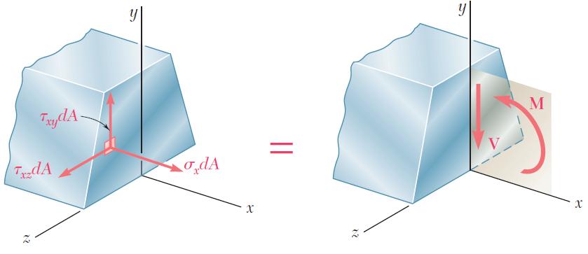
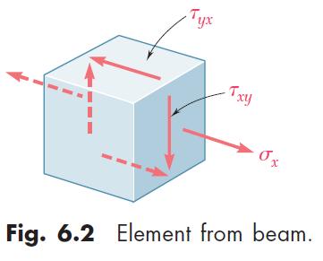
9 Determination of the Shearing Stress in a Beam The average shearing stress on the horizontal face of the element is obtained by dividing the shearing force on the element by the area of the face. t ave H A t q x A x t x On the upper and lower surfaces of the beam, t yx = 0. t follows that t xy = 0 on the upper and lower edges of the transverse sections. f the width of the beam is comparable or large relative to its depth, the shearing stresses at D 1 and D 2 are significantly higher than at D. 6-9

 beams t ave t max t V A web")
10 Shearing Stresses t xy in Common Types of Beams For a narrow rectangular beam, t t xy max b V 2 A V 1 2 A y c 2 2 For American Standard (S-beam) and wide-flange (W-beam) beams t ave t max t V A web 6-10
11 Sample Problem 6.2 SOLUTON: Develop shear and bending moment diagrams. dentify the maximums. A timber beam is to support the three concentrated loads shown. Knowing that for the grade of timber used, all 1800psi t 120psi all determine the minimum required depth d of the beam. Determine the beam depth based on allowable normal stress. Determine the beam depth based on allowable shear stress. Required beam depth is equal to the larger of the two depths found. 6-11

12 Sample Problem 6.2 SOLUTON: Develop shear and bending moment diagrams. dentify the maximums. V M max max kips 7.5kip ft 90kip in 6-12
13 Sample Problem 6.2 S 1 12 c 1 6 bd 1 6 bd.5in. 2 d in. d 2 Determine the beam depth based on allowable normal stress. all M S 1800 psi max 9010 d 9.26in. 0.58in. lb in. Determine the beam depth based on allowable shear stress. V t max all 2 A 000lb 120 psi 2.5in. d d 10.71in. d 2 Required beam depth is equal to the larger of the two. d 10.71in. 6-1

14 Example 6.04 SOLUTON: Determine the shear force per unit length along each edge of the upper plank. Based on the spacing between nails, determine the shear force in each nail. A square box beam is constructed from four planks as shown. Knowing that the spacing between nails is 1.5 in. and the beam is subjected to a vertical shear of magnitude V = 600 lb, determine the shearing force in each nail. 6-14
15 Example 6.04 SOLUTON: For the upper plank, Q Ay 4.22in 0.75in. in in. For the overall beam cross-section, in 1 in 27.42in 4 12 Determine the shear force per unit length along each edge of the upper plank. q f 600lb 4.22in 27.42in q lb in edge force per unit length 4 lb 92. in Based on the spacing between nails, determine the shear force in each nail. F lb f in in F 80.8lb 6-15


16 Shearing Stresses in Thin-Walled Members Consider a segment of a wide-flange beam subjected to the vertical shear V. The longitudinal shear force on the element is H t zx t xz x The corresponding shear stress is NOTE: t xy 0 t xz 0 H t x t Previously found a similar expression for the shearing stress in the web t xy t in the flanges in the web 6-16
17 Shearing Stresses in Thin-Walled Members The variation of shear flow across the section depends only on the variation of the first moment. q t For a box beam, q grows smoothly from zero at A to a maximum at C and C and then decreases back to zero at E. The sense of q in the horizontal portions of the section may be deduced from the sense in the vertical portions or the sense of the shear V. 6-17

18 Shearing Stresses in Thin-Walled Members For a wide-flange beam, the shear flow increases symmetrically from zero at A and A, reaches a maximum at C and the decreases to zero at E and E. The continuity of the variation in q and the merging of q from section branches suggests an analogy to fluid flow. 6-18
19 Sample Problem 6. SOLUTON: For the shaded area, Q 4.1in 0.770in 4.815in 15.98in Knowing that the vertical shear is 50 kips in a W10x68 rolled-steel beam, determine the horizontal shearing stress in the top flange at the point a. The shear stress at a, t t t 2.6ksi 50kips 15.98in 4 94in 0.770in 6-19
MECHANICS OF MATERIALS
 CHAPTER 6 MECHANCS OF MATERALS Ferdinand P. Beer E. Russell Johnston, Jr. John T. DeWolf David F. Mazurek Lecture Notes: J. Walt Oler Texas Tech University Shearing Stresses in Beams and Thin- Walled Members
MECHANICS OF MATERIALS
 CHAPTER MECHANCS OF MATERALS Ferdinand P. Beer E. Russell Johnston, Jr. John T. DeWolf Lecture Notes: J. Walt Oler Texas Tech University Shearing Stresses in Beams and Thin- Walled Members 006 The McGraw-Hill
MECHANICS OF MATERIALS
 009 The McGraw-Hill Companies, nc. All rights reserved. Fifth S E CHAPTER 6 MECHANCS OF MATERALS Ferdinand P. Beer E. Russell Johnston, Jr. John T. DeWolf David F. Mazurek Lecture Notes: J. Walt Oler Texas
MECHANICS OF MATERIALS
 2009 The McGraw-Hill Companies, Inc. All rights reserved. Fifth SI Edition CHAPTER 6 MECHANICS OF MATERIALS Ferdinand P. Beer E. Russell Johnston, Jr. John T. DeWolf David F. Mazurek Lecture Notes: J.
Mechanics of Solids I. Transverse Loading
 Mechanics of Solids I Transverse Loading Introduction o Transverse loading applied to a beam results in normal and shearing stresses in transverse sections. o Distribution of normal and shearing stresses
EMA 3702 Mechanics & Materials Science (Mechanics of Materials) Chapter 6 Shearing Stress in Beams & Thin-Walled Members
 Chapter 6 Shearing Stress in Beams & Thin-Walled Members") EMA 3702 Mechanics & Materials Science (Mechanics of Materials) Chapter 6 Shearing Stress in Beams & Thin-Walled Members Beams Bending & Shearing EMA 3702 Mechanics & Materials Science Zhe Cheng (2018)
EMA 3702 Mechanics & Materials Science (Mechanics of Materials) Chapter 6 Shearing Stress in Beams & Thin-Walled Members Beams Bending & Shearing EMA 3702 Mechanics & Materials Science Zhe Cheng (2018)
MECHANICS OF MATERIALS
 CHTER MECHNICS OF MTERILS 10 Ferdinand. Beer E. Russell Johnston, Jr. Columns John T. DeWolf cture Notes: J. Walt Oler Texas Tech University 006 The McGraw-Hill Companies, Inc. ll rights reserved. Columns
7 TRANSVERSE SHEAR transverse shear stress longitudinal shear stresses
 7 TRANSVERSE SHEAR Before we develop a relationship that describes the shear-stress distribution over the cross section of a beam, we will make some preliminary remarks regarding the way shear acts within
MECHANICS OF MATERIALS
 Third E CHAPTER 2 Stress MECHANICS OF MATERIALS Ferdinand P. Beer E. Russell Johnston, Jr. John T. DeWolf Lecture Notes: J. Walt Oler Texas Tech University and Strain Axial Loading Contents Stress & Strain:
MECHANICS OF MATERIALS
 Third E CHAPTER 1 Introduction MECHANICS OF MATERIALS Ferdinand P. Beer E. Russell Johnston, Jr. John T. DeWolf Lecture Notes: J. Walt Oler Texas Tech University Concept of Stress Contents Concept of Stress
CHAPTER 6: Shearing Stresses in Beams
 (130) CHAPTER 6: Shearing Stresses in Beams When a beam is in pure bending, the only stress resultants are the bending moments and the only stresses are the normal stresses acting on the cross sections.
MECHANICS OF MATERIALS
 00 The cgraw-hill Copanies, Inc. All rights reserved. Third E CHAPTER 8 Principle ECHANICS OF ATERIALS Ferdinand P. Beer E. Russell Johnston, Jr. John T. DeWolf Lecture Notes: J. Walt Oler Texas Tech University
MECHANICS OF MATERIALS
 00 The McGraw-Hill Copanies, Inc. All rights reserved. T Edition CHAPTER MECHANICS OF MATERIALS Ferdinand P. Beer E. Russell Johnston, Jr. John T. DeWolf Lecture Notes: J. Walt Oler Texas Tech University
[8] Bending and Shear Loading of Beams
![[8] Bending and Shear Loading of Beams](/thumbs/92/110949676.jpg "[8] Bending and Shear Loading of Beams") [8] Bending and Shear Loading of Beams Page 1 of 28 [8] Bending and Shear Loading of Beams [8.1] Bending of Beams (will not be covered in class) [8.2] Bending Strain and Stress [8.3] Shear in Straight
[8] Bending and Shear Loading of Beams Page 1 of 28 [8] Bending and Shear Loading of Beams [8.1] Bending of Beams (will not be covered in class) [8.2] Bending Strain and Stress [8.3] Shear in Straight
Stress Analysis Lecture 4 ME 276 Spring Dr./ Ahmed Mohamed Nagib Elmekawy
 Stress Analysis Lecture 4 ME 76 Spring 017-018 Dr./ Ahmed Mohamed Nagib Elmekawy Shear and Moment Diagrams Beam Sign Convention The positive directions are as follows: The internal shear force causes a
MECHANICS OF MATERIALS
 Third CHTR Stress MCHNICS OF MTRIS Ferdinand. Beer. Russell Johnston, Jr. John T. DeWolf ecture Notes: J. Walt Oler Texas Tech University and Strain xial oading Contents Stress & Strain: xial oading Normal
MECHANICS OF MATERIALS
 STATICS AND MECHANICS OF MATERIALS Ferdinand P. Beer E. Russell Johnston, Jr, John T. DeWolf David E Mazurek \Cawect Mc / iur/» Craw SugomcT Hilt Introduction 1 1.1 What is Mechanics? 2 1.2 Fundamental
STATICS. Moments of Inertia VECTOR MECHANICS FOR ENGINEERS: Ninth Edition CHAPTER. Ferdinand P. Beer E. Russell Johnston, Jr.
 N E 9 Distributed CHAPTER VECTOR MECHANCS FOR ENGNEERS: STATCS Ferdinand P. Beer E. Russell Johnston, Jr. Lecture Notes: J. Walt Oler Teas Tech Universit Forces: Moments of nertia Contents ntroduction
This procedure covers the determination of the moment of inertia about the neutral axis.
 327 Sample Problems Problem 16.1 The moment of inertia about the neutral axis for the T-beam shown is most nearly (A) 36 in 4 (C) 236 in 4 (B) 136 in 4 (D) 736 in 4 This procedure covers the determination
BEAMS: SHEARING STRESS
 LECTURE Third Edition BEAMS: SHEARNG STRESS A. J. Clark Shool of Engineering Department of Civil and Environmental Engineering 14 Chapter 6.1 6.4 b Dr. brahim A. Assakkaf SPRNG 200 ENES 220 Mehanis of
MECHANICS OF MATERIALS
 009 The McGraw-Hill Companies, Inc. All rights reserved. Fifth SI Edition CHAPTER 7 MECHANICS OF MATERIALS Ferdinand P. Beer E. Russell Johnston, Jr. John T. DeWolf David F. Mazurek Transformations of
Homework 6.1 P = 1000 N. δ δ δ. 4 cm 4 cm 4 cm. 10 cm
 Homework 6.1 Three thick and wide boards are connected together by two parallel rows of uniformly distributed nails separated by longitude distance δ to form a beam that is subject to constant vertical
MECHANICS OF MATERIALS
 Third CHTR Stress MCHNICS OF MTRIS Ferdinand. Beer. Russell Johnston, Jr. John T. DeWolf ecture Notes: J. Walt Oler Texas Tech University and Strain xial oading Contents Stress & Strain: xial oading Normal
STATICS. Moments of Inertia VECTOR MECHANICS FOR ENGINEERS: Seventh Edition CHAPTER. Ferdinand P. Beer
 00 The McGraw-Hill Companies, nc. All rights reserved. Seventh E CHAPTER VECTOR MECHANCS FOR ENGNEERS: 9 STATCS Ferdinand P. Beer E. Russell Johnston, Jr. Distributed Forces: Lecture Notes: J. Walt Oler
Chapter Objectives. Copyright 2011 Pearson Education South Asia Pte Ltd
 Chapter Objectives To generalize the procedure by formulating equations that can be plotted so that they describe the internal shear and moment throughout a member. To use the relations between distributed
5. What is the moment of inertia about the x - x axis of the rectangular beam shown?
 1 of 5 Continuing Education Course #274 What Every Engineer Should Know About Structures Part D - Bending Strength Of Materials NOTE: The following question was revised on 15 August 2018 1. The moment
MECHANICS OF MATERIALS
 CHAPTER MECHANICS OF MATERIALS Ferdinand P. Beer E. Russell Johnston, Jr. John T. DeWolf Lecture Notes: J. Walt Oler Teas Tech Universit Transformations of Stress and Strain 006 The McGraw-Hill Companies,
STATICS. Distributed Forces: Moments of Inertia VECTOR MECHANICS FOR ENGINEERS: Eighth Edition CHAPTER. Ferdinand P. Beer E. Russell Johnston, Jr.
 007 The McGraw-Hill Companies, nc. All rights reserved. Eighth E CHAPTER 9 VECTOR MECHANCS FOR ENGNEERS: STATCS Ferdinand P. Beer E. Russell Johnston, Jr. Lecture Notes: J. Walt Oler Texas Tech University
MECHANICS OF MATERIALS
 2009 The McGraw-Hill Companies, Inc. All rights reserved. Fifth SI Edition CHAPTER 3 MECHANICS OF MATERIALS Ferdinand P. Beer E. Russell Johnston, Jr. John T. DeWolf David F. Mazurek Torsion Lecture Notes:
Symmetric Bending of Beams
 Symmetric Bending of Beams beam is any long structural member on which loads act perpendicular to the longitudinal axis. Learning objectives Understand the theory, its limitations and its applications
Shear Stress. Horizontal Shear in Beams. Average Shear Stress Across the Width. Maximum Transverse Shear Stress. = b h
 Shear Stre Due to the preence of the hear force in beam and the fact that t xy = t yx a horizontal hear force exit in the beam that tend to force the beam fiber to lide. Horizontal Shear in Beam The horizontal
7.6 Stress in symmetrical elastic beam transmitting both shear force and bending moment
 7.6 Stress in symmetrical elastic beam transmitting both shear force and bending moment à It is more difficult to obtain an exact solution to this problem since the presence of the shear force means that
MECHANICS OF MATERIALS
 00 The McGraw-Hill Companies, Inc. All rights reserved. T Edition CHAPTER MECHANICS OF MATERIALS Ferdinand P. Beer E. Russell Johnston, Jr. John T. DeWolf Lecture Notes: J. Walt Oler Teas Tech Universit
MECHANICS OF MATERIALS. Analysis of Beams for Bending
 MECHANICS OF MATERIALS Analysis of Beams for Bending By NUR FARHAYU ARIFFIN Faculty of Civil Engineering & Earth Resources Chapter Description Expected Outcomes Define the elastic deformation of an axially
CHAPTER 4. Stresses in Beams
 CHAPTER 4 Stresses in Beams Problem 1. A rolled steel joint (RSJ) of -section has top and bottom flanges 150 mm 5 mm and web of size 00 mm 1 mm. t is used as a simply supported beam over a span of 4 m
Homework No. 1 MAE/CE 459/559 John A. Gilbert, Ph.D. Fall 2004
 Homework No. 1 MAE/CE 459/559 John A. Gilbert, Ph.D. 1. A beam is loaded as shown. The dimensions of the cross section appear in the insert. the figure. Draw a complete free body diagram showing an equivalent
Beam Bending Stresses and Shear Stress
 Beam Bending Stresses and Shear Stress Notation: A = name or area Aweb = area o the web o a wide lange section b = width o a rectangle = total width o material at a horizontal section c = largest distance
Chapter 7: Internal Forces
 Chapter 7: Internal Forces Chapter Objectives To show how to use the method of sections for determining the internal loadings in a member. To generalize this procedure by formulating equations that can
MECHANICS OF MATERIALS
 Fifth SI Edition CHTER 1 MECHNICS OF MTERILS Ferdinand. Beer E. Russell Johnston, Jr. John T. DeWolf David F. Mazurek Introduction Concept of Stress Lecture Notes: J. Walt Oler Teas Tech University Contents
CHAPTER -6- BENDING Part -1-
 Ishik University / Sulaimani Civil Engineering Department Mechanics of Materials CE 211 CHAPTER -6- BENDING Part -1-1 CHAPTER -6- Bending Outlines of this chapter: 6.1. Chapter Objectives 6.2. Shear and
MECE 3321 MECHANICS OF SOLIDS CHAPTER 1
 MECE 3321 MECHANICS O SOLIDS CHAPTER 1 Samantha Ramirez, MSE WHAT IS MECHANICS O MATERIALS? Rigid Bodies Statics Dynamics Mechanics Deformable Bodies Solids/Mech. Of Materials luids 1 WHAT IS MECHANICS
IDE 110 Mechanics of Materials Spring 2006 Final Examination FOR GRADING ONLY
 Spring 2006 Final Examination STUDENT S NAME (please print) STUDENT S SIGNATURE STUDENT NUMBER IDE 110 CLASS SECTION INSTRUCTOR S NAME Do not turn this page until instructed to start. Write your name on
Chapter 7: Bending and Shear in Simple Beams
 Chapter 7: Bending and Shear in Simple Beams Introduction A beam is a long, slender structural member that resists loads that are generally applied transverse (perpendicular) to its longitudinal axis.
= 50 ksi. The maximum beam deflection Δ max is not = R B. = 30 kips. Notes for Strength of Materials, ET 200
 Notes for Strength of Materials, ET 00 Steel Six Easy Steps Steel beam design is about selecting the lightest steel beam that will support the load without exceeding the bending strength or shear strength
MECHANICS OF MATERIALS
 GE SI CHAPTER 3 MECHANICS OF MATERIALS Ferdinand P. Beer E. Russell Johnston, Jr. John T. DeWolf David F. Mazurek Torsion Lecture Notes: J. Walt Oler Texas Tech University Torsional Loads on Circular Shafts
6. Bending CHAPTER OBJECTIVES
 CHAPTER OBJECTIVES Determine stress in members caused by bending Discuss how to establish shear and moment diagrams for a beam or shaft Determine largest shear and moment in a member, and specify where
CHAPTER 4: BENDING OF BEAMS
 (74) CHAPTER 4: BENDING OF BEAMS This chapter will be devoted to the analysis of prismatic members subjected to equal and opposite couples M and M' acting in the same longitudinal plane. Such members are
MECE 3321: Mechanics of Solids Chapter 6
 MECE 3321: Mechanics of Solids Chapter 6 Samantha Ramirez Beams Beams are long straight members that carry loads perpendicular to their longitudinal axis Beams are classified by the way they are supported
Solution: The moment of inertia for the cross-section is: ANS: ANS: Problem 15.6 The material of the beam in Problem
 Problem 15.4 The beam consists of material with modulus of elasticity E 14x10 6 psi and is subjected to couples M 150, 000 in lb at its ends. (a) What is the resulting radius of curvature of the neutral
Mechanics of Materials
 Mechanics of Materials 2. Introduction Dr. Rami Zakaria References: 1. Engineering Mechanics: Statics, R.C. Hibbeler, 12 th ed, Pearson 2. Mechanics of Materials: R.C. Hibbeler, 9 th ed, Pearson 3. Mechanics
Steel Cross Sections. Structural Steel Design
 Steel Cross Sections Structural Steel Design PROPERTIES OF SECTIONS Perhaps the most important properties of a beam are the depth and shape of its cross section. There are many to choose from, and there
 UNIT III DEFLECTION OF BEAMS 1. What are the methods for finding out the slope and deflection at a section? The important methods used for finding out the slope and deflection at a section in a loaded
Strength of Materials Prof. Dr. Suraj Prakash Harsha Mechanical and Industrial Engineering Department Indian Institute of Technology, Roorkee
 Strength of Materials Prof. Dr. Suraj Prakash Harsha Mechanical and Industrial Engineering Department Indian Institute of Technology, Roorkee Lecture - 28 Hi, this is Dr. S. P. Harsha from Mechanical and
MECHANICS OF MATERIALS Sample Problem 4.2
 Sample Problem 4. SOLUTON: Based on the cross section geometry, calculate the location of the section centroid and moment of inertia. ya ( + Y Ad ) A A cast-iron machine part is acted upon by a kn-m couple.
Mechanics of Solids notes
 Mechanics of Solids notes 1 UNIT II Pure Bending Loading restrictions: As we are aware of the fact internal reactions developed on any cross-section of a beam may consists of a resultant normal force,
Beams III -- Shear Stress: 1
 Beams III -- Shear Stress: 1 Internal Shear Force Shear Stress Formula for Beams The First Area Moment, Q Shear Stresses in Beam Flanges Shear Distribution on an I Beam 1 2 In this stack we will derive
Mechanics in Energy Resources Engineering - Chapter 5 Stresses in Beams (Basic topics)
") Week 7, 14 March Mechanics in Energy Resources Engineering - Chapter 5 Stresses in Beams (Basic topics) Ki-Bok Min, PhD Assistant Professor Energy Resources Engineering i Seoul National University Shear
Week 7, 14 March Mechanics in Energy Resources Engineering - Chapter 5 Stresses in Beams (Basic topics) Ki-Bok Min, PhD Assistant Professor Energy Resources Engineering i Seoul National University Shear
Montgomery County Community College EGR 213 Mechanics of Materials 3-2-2
 Montgomery County Community College EGR 213 Mechanics of Materials 3-2-2 COURSE DESCRIPTION: This course covers the deformation of beams and shafts using energy methods and structural analysis, the analysis
M5 Simple Beam Theory (continued)
") M5 Simple Beam Theory (continued) Reading: Crandall, Dahl and Lardner 7.-7.6 In the previous lecture we had reached the point of obtaining 5 equations, 5 unknowns by application of equations of elasticity
M5 Simple Beam Theory (continued) Reading: Crandall, Dahl and Lardner 7.-7.6 In the previous lecture we had reached the point of obtaining 5 equations, 5 unknowns by application of equations of elasticity
[5] Stress and Strain
![[5] Stress and Strain](/thumbs/95/123344550.jpg "[5] Stress and Strain") [5] Stress and Strain Page 1 of 34 [5] Stress and Strain [5.1] Internal Stress of Solids [5.2] Design of Simple Connections (will not be covered in class) [5.3] Deformation and Strain [5.4] Hooke s Law
[5] Stress and Strain Page 1 of 34 [5] Stress and Strain [5.1] Internal Stress of Solids [5.2] Design of Simple Connections (will not be covered in class) [5.3] Deformation and Strain [5.4] Hooke s Law
Equilibrium. Rigid Bodies VECTOR MECHANICS FOR ENGINEERS: STATICS. Eighth Edition CHAPTER. Ferdinand P. Beer E. Russell Johnston, Jr.
 Eighth E 4 Equilibrium CHAPTER VECTOR MECHANICS FOR ENGINEERS: STATICS Ferdinand P. Beer E. Russell Johnston, Jr. Lecture Notes: J. Walt Oler Texas Tech University of Rigid Bodies Contents Introduction
STATICS. Bodies VECTOR MECHANICS FOR ENGINEERS: Ninth Edition CHAPTER. Ferdinand P. Beer E. Russell Johnston, Jr.
 N E 4 Equilibrium CHAPTER VECTOR MECHANICS FOR ENGINEERS: STATICS Ferdinand P. Beer E. Russell Johnston, Jr. Lecture Notes: J. Walt Oler Texas Tech University of Rigid Bodies 2010 The McGraw-Hill Companies,
Design of Reinforced Concrete Beam for Shear
 Lecture 06 Design of Reinforced Concrete Beam for Shear By: Civil Engineering Department UET Peshawar drqaisarali@uetpeshawar.edu.pk Topics Addressed Shear Stresses in Rectangular Beams Diagonal Tension
STATICS. Introduction Lecture Notes: J. Walt Oler Texas Tech University. Vector Mechanics for Engineers: Statics VECTOR MECHANICS FOR ENGINEERS:
 CHAPTER VECTOR MECHANICS FOR ENGINEERS: STATICS 1 Ferdinand P. Beer E. Russell Johnston, Jr. Introduction Lecture Notes: J. Walt Oler Texas Tech University Contents What is Mechanics? Fundamental Concepts
EMA 3702 Mechanics & Materials Science (Mechanics of Materials) Chapter 5 Beams for Bending
 Chapter 5 Beams for Bending") MA 3702 Mechanics & Materials Science (Mechanics of Materials) Chapter 5 Beams for Bending Introduction esign of beams for mechanical or civil/structural applications Transverse loading in most cases for
MA 3702 Mechanics & Materials Science (Mechanics of Materials) Chapter 5 Beams for Bending Introduction esign of beams for mechanical or civil/structural applications Transverse loading in most cases for
Use Hooke s Law (as it applies in the uniaxial direction),
,") 0.6 STRSS-STRAIN RLATIONSHIP Use the principle of superposition Use Poisson s ratio, v lateral longitudinal Use Hooke s Law (as it applies in the uniaxial direction), x x v y z, y y vx z, z z vx y Copyright
0.6 STRSS-STRAIN RLATIONSHIP Use the principle of superposition Use Poisson s ratio, v lateral longitudinal Use Hooke s Law (as it applies in the uniaxial direction), x x v y z, y y vx z, z z vx y Copyright
Samantha Ramirez, MSE
 Samantha Ramirez, MSE Centroids The centroid of an area refers to the point that defines the geometric center for the area. In cases where the area has an axis of symmetry, the centroid will lie along
Chapter 12 Plate Bending Elements. Chapter 12 Plate Bending Elements
 CIVL 7/8117 Chapter 12 - Plate Bending Elements 1/34 Chapter 12 Plate Bending Elements Learning Objectives To introduce basic concepts of plate bending. To derive a common plate bending element stiffness
Problem d d d B C E D. 0.8d. Additional lecturebook examples 29 ME 323
 Problem 9.1 Two beam segments, AC and CD, are connected together at C by a frictionless pin. Segment CD is cantilevered from a rigid support at D, and segment AC has a roller support at A. a) Determine
By Dr. Mohammed Ramidh
 Engineering Materials Design Lecture.6 the design of beams By Dr. Mohammed Ramidh 6.1 INTRODUCTION Finding the shear forces and bending moments is an essential step in the design of any beam. we usually
NAME: Given Formulae: Law of Cosines: Law of Sines:
 NME: Given Formulae: Law of Cosines: EXM 3 PST PROBLEMS (LESSONS 21 TO 28) 100 points Thursday, November 16, 2017, 7pm to 9:30, Room 200 You are allowed to use a calculator and drawing equipment, only.
2. Rigid bar ABC supports a weight of W = 50 kn. Bar ABC is pinned at A and supported at B by rod (1). What is the axial force in rod (1)?
. What is the axial force in rod (1)?") IDE 110 S08 Test 1 Name: 1. Determine the internal axial forces in segments (1), (2) and (3). (a) N 1 = kn (b) N 2 = kn (c) N 3 = kn 2. Rigid bar ABC supports a weight of W = 50 kn. Bar ABC is pinned at
IDE 110 S08 Test 1 Name: 1. Determine the internal axial forces in segments (1), (2) and (3). (a) N 1 = kn (b) N 2 = kn (c) N 3 = kn 2. Rigid bar ABC supports a weight of W = 50 kn. Bar ABC is pinned at
Method of Virtual Work Frame Deflection Example Steven Vukazich San Jose State University
 Method of Virtual Work Frame Deflection xample Steven Vukazich San Jose State University Frame Deflection xample 9 k k D 4 ft θ " # The statically determinate frame from our previous internal force diagram
Design of Reinforced Concrete Beam for Shear
 Lecture 06 Design of Reinforced Concrete Beam for Shear By: Prof Dr. Qaisar Ali Civil Engineering Department UET Peshawar drqaisarali@uetpeshawar.edu.pk 1 Topics Addressed Shear Stresses in Rectangular
ARC 341 Structural Analysis II. Lecture 10: MM1.3 MM1.13
 ARC241 Structural Analysis I Lecture 10: MM1.3 MM1.13 MM1.4) Analysis and Design MM1.5) Axial Loading; Normal Stress MM1.6) Shearing Stress MM1.7) Bearing Stress in Connections MM1.9) Method of Problem
Chapter 3. Load and Stress Analysis
 Chapter 3 Load and Stress Analysis 2 Shear Force and Bending Moments in Beams Internal shear force V & bending moment M must ensure equilibrium Fig. 3 2 Sign Conventions for Bending and Shear Fig. 3 3
EMA 3702 Mechanics & Materials Science (Mechanics of Materials) Chapter 4 Pure Bending
 Chapter 4 Pure Bending") EA 3702 echanics & aterials Science (echanics of aterials) Chapter 4 Pure Bending Pure Bending Ch 2 Aial Loading & Parallel Loading: uniform normal stress and shearing stress distribution Ch 3 Torsion:
EA 3702 echanics & aterials Science (echanics of aterials) Chapter 4 Pure Bending Pure Bending Ch 2 Aial Loading & Parallel Loading: uniform normal stress and shearing stress distribution Ch 3 Torsion:
Chapter 8: Bending and Shear Stresses in Beams
 Chapter 8: Bending and Shear Stresses in Beams Introduction One of the earliest studies concerned with the strength and deflection of beams was conducted by Galileo Galilei. Galileo was the first to discuss
MOMENTS OF INERTIA FOR AREAS, RADIUS OF GYRATION OF AN AREA, & MOMENTS OF INTERTIA BY INTEGRATION
 MOMENTS OF INERTIA FOR AREAS, RADIUS OF GYRATION OF AN AREA, & MOMENTS OF INTERTIA BY INTEGRATION Today s Objectives: Students will be able to: a) Define the moments of inertia (MoI) for an area. b) Determine
UNIT- I Thin plate theory, Structural Instability:
 UNIT- I Thin plate theory, Structural Instability: Analysis of thin rectangular plates subject to bending, twisting, distributed transverse load, combined bending and in-plane loading Thin plates having
Supplement: Statically Indeterminate Frames
 : Statically Indeterminate Frames Approximate Analysis - In this supplement, we consider another approximate method of solving statically indeterminate frames subjected to lateral loads known as the. Like
Shear Stress Example: 1 (3/30/00)
") Shear Stress Example: 1 (3/30/00) Shear Stress Example Determine the largest shear stress for the beam shown. Given the 7' beam with the cross-section shown above left, what is the largest shear stress
Shear Stress Example: 1 (3/30/00) Shear Stress Example Determine the largest shear stress for the beam shown. Given the 7' beam with the cross-section shown above left, what is the largest shear stress
Chapter 5 Structural Elements: The truss & beam elements
 Institute of Structural Engineering Page 1 Chapter 5 Structural Elements: The truss & beam elements Institute of Structural Engineering Page 2 Chapter Goals Learn how to formulate the Finite Element Equations
AREAS, RADIUS OF GYRATION
 Chapter 10 MOMENTS of INERTIA for AREAS, RADIUS OF GYRATION Today s Objectives: Students will be able to: a) Define the moments of inertia (MoI) for an area. b) Determine the MoI for an area by integration.
4.MECHANICAL PROPERTIES OF MATERIALS
 4.MECHANICAL PROPERTIES OF MATERIALS The diagram representing the relation between stress and strain in a given material is an important characteristic of the material. To obtain the stress-strain diagram
Jeff Brown Hope College, Department of Engineering, 27 Graves Pl., Holland, Michigan, USA UNESCO EOLSS
 MECHANICS OF MATERIALS Jeff Brown Hope College, Department of Engineering, 27 Graves Pl., Holland, Michigan, USA Keywords: Solid mechanics, stress, strain, yield strength Contents 1. Introduction 2. Stress
MECHANICS OF MATERIALS. Prepared by Engr. John Paul Timola
 MECHANICS OF MATERIALS Prepared by Engr. John Paul Timola Mechanics of materials branch of mechanics that studies the internal effects of stress and strain in a solid body. stress is associated with the
Comb resonator design (2)
") Lecture 6: Comb resonator design () -Intro Intro. to Mechanics of Materials School of Electrical l Engineering i and Computer Science, Seoul National University Nano/Micro Systems & Controls Laboratory
Lecture 6: Comb resonator design () -Intro Intro. to Mechanics of Materials School of Electrical l Engineering i and Computer Science, Seoul National University Nano/Micro Systems & Controls Laboratory
ES120 Spring 2018 Section 7 Notes
 ES120 Spring 2018 Section 7 Notes Matheus Fernandes March 29, 2018 Problem 1: For the beam and loading shown, (a) determine the equations of the shear and bending-moment curves, (b) draw the shear and
Interaction Diagram Dumbbell Concrete Shear Wall Unsymmetrical Boundary Elements
 Interaction Diagram Dumbbell Concrete Shear Wall Unsymmetrical Boundary Elements Interaction Diagram - Dumbbell Concrete Shear Wall Unsymmetrical Boundary Elements Investigate the capacity for the irregular
Physical Science and Engineering. Course Information. Course Number: ME 100
 Physical Science and Engineering Course Number: ME 100 Course Title: Course Information Basic Principles of Mechanics Academic Semester: Fall Academic Year: 2016-2017 Semester Start Date: 8/21/2016 Semester
6.5 Cables: Concentrated Loads
 6.5 ables: oncentrated Loads 6.5 ables: oncentrated Loads Procedures and Strategies, page 1 of 3 Procedures and Strategies for Solving Problems Involving ables With oncentrated Loads 1. Pass sections through
Properties of Sections
 ARCH 314 Structures I Test Primer Questions Dr.-Ing. Peter von Buelow Properties of Sections 1. Select all that apply to the characteristics of the Center of Gravity: A) 1. The point about which the body
Advanced Structural Analysis EGF Section Properties and Bending
 Advanced Structural Analysis EGF316 3. Section Properties and Bending 3.1 Loads in beams When we analyse beams, we need to consider various types of loads acting on them, for example, axial forces, shear
Stress Transformation Equations: u = +135 (Fig. a) s x = 80 MPa s y = 0 t xy = 45 MPa. we obtain, cos u + t xy sin 2u. s x = s x + s y.
 s x = 80 MPa s y = 0 t xy = 45 MPa. we obtain, cos u + t xy sin 2u. s x = s x + s y.") 014 Pearson Education, Inc., Upper Saddle River, NJ. All rights reserved. This material is protected under all copyright laws as they currently 9 7. Determine the normal stress and shear stress acting
014 Pearson Education, Inc., Upper Saddle River, NJ. All rights reserved. This material is protected under all copyright laws as they currently 9 7. Determine the normal stress and shear stress acting
Chapter 7 FORCES IN BEAMS AND CABLES
 hapter 7 FORES IN BEAMS AN ABLES onsider a straight two-force member AB subjected at A and B to equal and opposite forces F and -F directed along AB. utting the member AB at and drawing the free-body B
COLUMNS: BUCKLING (DIFFERENT ENDS)
") COLUMNS: BUCKLING (DIFFERENT ENDS) Buckling of Long Straight Columns Example 4 Slide No. 1 A simple pin-connected truss is loaded and supported as shown in Fig. 1. All members of the truss are WT10 43
COLUMNS: BUCKLING (DIFFERENT ENDS) Buckling of Long Straight Columns Example 4 Slide No. 1 A simple pin-connected truss is loaded and supported as shown in Fig. 1. All members of the truss are WT10 43
BENCHMARK LINEAR FINITE ELEMENT ANALYSIS OF LATERALLY LOADED SINGLE PILE USING OPENSEES & COMPARISON WITH ANALYTICAL SOLUTION
 BENCHMARK LINEAR FINITE ELEMENT ANALYSIS OF LATERALLY LOADED SINGLE PILE USING OPENSEES & COMPARISON WITH ANALYTICAL SOLUTION Ahmed Elgamal and Jinchi Lu October 07 Introduction In this study: I) The response
SHEAR STRESS DISTRIBUTION
 T,, CHAPTER 7 SHEAR STRESS DSTRBUTON Summary The shear stress in a beam at any transverse cross-section in its length, and at a point a vertical distance y from the neutral axis, resulting from bending
Determine the resultant internal loadings acting on the cross section at C of the beam shown in Fig. 1 4a.
 E X M P L E 1.1 Determine the resultant internal loadings acting on the cross section at of the beam shown in Fig. 1 a. 70 N/m m 6 m Fig. 1 Support Reactions. This problem can be solved in the most direct