BASIC EQUATION. Rotational speed. u = linear velocity in m/s r = radius in m ω = angular velocity in rad/s D = diameter in m N = rotation per minute
|
|
|
- Polly Arnold
- 5 years ago
- Views:
Transcription

1 CENTRIFUGAL PUMP
2 BASIC EQUATION Rotational speed u = rω = πdn 60 u = linear velocity in m/s r = radius in m ω = angular velocity in rad/s D = diameter in m N = rotation per minute Power Power = F V = P A V = ρgh AV = ρgh Q Work Power = ρgq h Work = Torque Angular velocity Work = Force Distance
3 TURBOMACHINES Turbomachines are the commonly employed devices that either supply or extract energy from a flowing fluid by means of rotating propellers or vanes. PUMP: Pump adds energy to a system, with the result that the pressure is increased. It also causes flow to occur or it increases the rate of flow. TURBINE: A turbine extracts energy from a system and converts it to some other useful form, typically, to electric power. Hydroturbine: is a machine that generates power from high-pressure water; relatively large conduits or tunnels deliver fluid to closed turbines in order to generate power. Another example: steam turbine and air turbine.
4 PUMP CLASSIFICATION
 Housing or casing: which directs the liquid into the impeller region and transports it away under a high pressure. The impeller is mounted on a shaft and is often driven by an electric motor.")
5 CENTRIFUGAL PUMP A centrifugal pump consists of two principal parts: (1) Impeller: which imparts a rotary motion to the liquid. (2) Housing or casing: which directs the liquid into the impeller region and transports it away under a high pressure. The impeller is mounted on a shaft and is often driven by an electric motor. The casing includes the suction and discharge nozzles and houses the impeller assembly. The portion of the casing surrounding the impeller is termed the volute. Liquid enters through the suction nozzle to the impeller eye and travels along the shroud, developing a rotary motion due to the impeller vanes.


6 It leaves the volute casing peripherally at a higher pressure through the discharging nozzle. Some single-suction impellers are open, with the front shroud removed. Double-suction impellers have liquid entering from both sides.
7
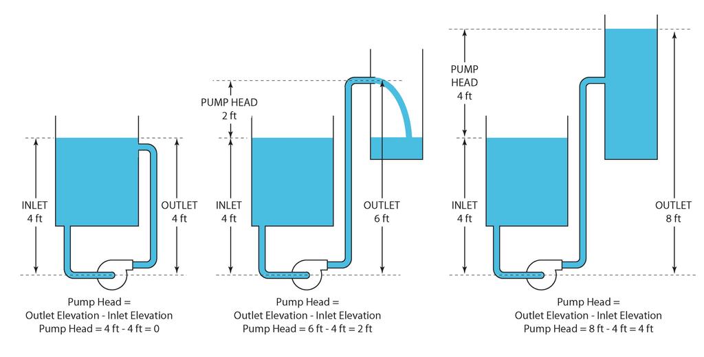
8 HEAD OF PUMP (Manometric head) This is defined by British Standards as the sum of the actual lift (H) + the friction losses in the pipes (hf)+ the discharge velocity head. H s = H + h t + V u v 2g = P v P x ρg + V v v v V x 2g However, for special pumps allowance must also be made for the velocity of flow towards the suction intake and any pressure differences at the water surfaces in the supply and receiving tanks. Commonly the suction and delivery pipes are of equal diameter. In which case: H s = P v P x ρg
9
10
11 VELOCITY TRIANGLE
12 Legend: At inlet (1) u x = r x ω = Tangetial velocity of impeller v x = Absolute velocity at α x to tangent v }x = v x u x = Relataive velocity to impeller blade Component velocity for v x : v ~x = Whirl velocity v tx = Radial flow velocity β x = Inlet blade angle At outlet (2) u v = r v ω = Tangetial velocity of impeller v v = Absolute velocity at α v to tangent v }v = v v u v = Relataive velocity to impeller blade Component velocity for v v : v ~v = Whirl velocity v tv = Radial flow velocity β v = Inlet blade angle
13

14 BLADE TYPE 1. Forward blade 2. Radial blade 3. Backward blade FORWARD BLADE

15 RADIAL BLADE

16 BACKWARD BLADE
17 THE EFFECT OF BLADE TYPE Centrifugal pumps do not always have backward curved vanes. But when they do, it is mostly for fluids in the incompressible regime of operation such as water. For compressible operation of fluids such as air, forward curve-vaned centrifugal pumps are used. The net ideal head developed by a centrifugal pump is given by: H uƒ = A BQ Q = volume flow rate at the impeller outlet A, B = constant for a given impeller running at a given speed Additionally, B cot β v.
18 Do note that the value of the actual head developed by the pump will be lower than this ideal value owing to shocks Hˆ Š Œ = K x Q u Q v Q u = design volume flow rate Q = actual volume flow rate Friction can be calculated by: h t = K v Q v which together constitute hydraulic losses.
19 The power required to drive the pump to provide a given flow-rate is given as: P = ρgq H uƒ The representative curves are given below.
20 As is evident from the power-discharge characteristics of the radial and forward vaned centrifugal pump, the power requirement increases monotonically with an increase in discharge. Hence, if the pump motor is rated for maximum power, then it will remain under-utilized for most of the operating time, and result in an increased cost due to its higher rating. On the other hand, if a motor is rated at the design point, and due to some reason the flow-rate exceeds the design flow rate, then the power requirement will shoot up (in case of forward and radial vanes only), causing overloading and motor failure. However, for backward curve-vaned centrifugal pumps, if the flow-rate exceeds the design flow rate (occurs quite close to the maxima of the power-discharge curve), then contrary to the earlier case, the power requirement drops down as evident from the curves. This enables the motor which is rated at the design power to handle the entire range of flow-rates without any problems. The actual design point is located corresponding to the flowrate at which maximum efficiency occurs.
21 EULER HEAD Torque = kadar perubahan momentum sudut Momentum sudut = (jisim) (halaju tangen) (jejari) Momentum sudut masuk = mv ~x r x Momentum sudut keluar = mv ~v r v m = kadar jisim mengalir sesaat Kadar perubahan momentum sudut: T = mv ~v r v mv ~x r x m = ρav = ρq T = ρq v ~v r v v ~x r x Diketahui power ialah: P = Tω P = ρq v ~v r v v ~x r x ω Diketahui: u = rω u x = r x ω u v = r v ω r x = and r v =
22 Diketahui power ialah: P = ρq v ~v r v v ~x r x ω u v = ρq v ~v ω v u v ~x ω ω = ρq v ~v u v v ~x u x Power juga boleh ditulis sebagai: P = ρgq h Jika power adalah maksimum, nilai h ialah nilai maksimum, iaitu niai power dalam keadaan tiada kehilangan tenaga (losses, friction, etc). Nilai h boleh ditulis sebagai H (Euler head) P = ρgq H = ρq v ~v u v v ~x u x H = 1 g v ~vu v v ~x u x Ia kenali sebagai Euler head (turus Euler). Unitnya dalam meter (m). Ia adalah turus ideal yang dihasilkan oleh impeller (pendesak) dalam system pam.
23 PUMP EFFICIENCY (kecekapan pam) Manometric efficiency η s Š = Kuasa air yang dihasilkan Kuasa impeller = ρgq H s ρgq H = ρgq ρgq H s 1 g v ~vu v v ~x u x η s Š = gh s v ~v u v v ~x u x Mechanical efficiency η sƒ = Kuasa impeller Kuasa yang diberikan kepada syaf η sƒ = 1 g v ~vu v v ~x u x P š
24 Overall efficiency η Š = Kuasa air yang dihasilkan Kuasa yang diberikan kepada syaf η Š = ρgq H s P š
BASIC EQUATION. Rotational speed = = ABC 60
 CENTRIFUGAL PUMP BASIC EQUATION Rotational speed = =?@ = ABC 60 = = linear velocity in m/s? = radius in m @ = angular velocity in rad/s B = diameter in m C = rotation per minute Power OPQR? = S U = O V
Chapter Four Hydraulic Machines
 Contents 1- Introduction. - Pumps. Chapter Four Hydraulic Machines (لفرع الميكانيك العام فقط ( Turbines. -3 4- Cavitation in hydraulic machines. 5- Examples. 6- Problems; sheet No. 4 (Pumps) 7- Problems;
Chapter Four Hydraulic Machines
 Contents 1- Introduction. 2- Pumps. Chapter Four Hydraulic Machines (لفرع الميكانيك العام فقط ( Turbines. -3 4- Cavitation in hydraulic machines. 5- Examples. 6- Problems; sheet No. 4 (Pumps) 7- Problems;
CHAPTER TWO CENTRIFUGAL PUMPS 2.1 Energy Transfer In Turbo Machines
 7 CHAPTER TWO CENTRIFUGAL PUMPS 21 Energy Transfer In Turbo Machines Fig21 Now consider a turbomachine (pump or turbine) the total head (H) supplied by it is The power delivered to/by the fluid simply
Theory of turbo machine Effect of Blade Configuration on Characteristics of Centrifugal machines. Unit 2 (Potters & Wiggert Sec
 Theory of turbo machine Effect of Blade Configuration on Characteristics of Centrifugal machines Unit (Potters & Wiggert Sec. 1..1, &-607) Expression relating Q, H, P developed by Rotary machines Rotary
Department of Civil and Environmental Engineering CVNG 1001: Mechanics of Fluids
 INTRODUCTION Hydrodynamic Machines A hydromachine is a device used either for extracting energy from a fluid or to add energy to a fluid. There are many types of hydromachines and Figure 1 below illustrates
Introduction to Fluid Machines (Lectures 49 to 53)
") Introduction to Fluid Machines (Lectures 49 to 5) Q. Choose the crect answer (i) (ii) (iii) (iv) A hydraulic turbine rotates at N rpm operating under a net head H and having a discharge Q while developing
Introduction to Fluid Machines (Lectures 49 to 5) Q. Choose the crect answer (i) (ii) (iii) (iv) A hydraulic turbine rotates at N rpm operating under a net head H and having a discharge Q while developing
ENERGY TRANSFER BETWEEN FLUID AND ROTOR. Dr. Ir. Harinaldi, M.Eng Mechanical Engineering Department Faculty of Engineering University of Indonesia
 ENERGY TRANSFER BETWEEN FLUID AND ROTOR Dr. Ir. Harinaldi, M.Eng Mechanical Engineering Department Faculty of Engineering University of Indonesia Basic Laws and Equations Continuity Equation m m ρ mass
CHAPTER EIGHT P U M P I N G O F L I Q U I D S
 CHAPTER EIGHT P U M P I N G O F L I Q U I D S Pupmps are devices for supplying energy or head to a flowing liquid in order to overcome head losses due to friction and also if necessary, to raise liquid
Specific Static rotor work ( P P )
") The specific Static Rotor ork p 1 ρ Specific Static rotor work ( P P ) here P, P static pressures at points, (P P ) static pressure difference of the rotor ρ density, in case of a compressible medium average
The specific Static Rotor ork p 1 ρ Specific Static rotor work ( P P ) here P, P static pressures at points, (P P ) static pressure difference of the rotor ρ density, in case of a compressible medium average
Introduction to Turbomachinery
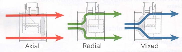
 1. Coordinate System Introduction to Turbomachinery Since there are stationary and rotating blades in turbomachines, they tend to form a cylindrical form, represented in three directions; 1. Axial 2. Radial
Centrifugal Machines Table of Contents
 NLNG Course 017 Table of Contents 1 Introduction and Basic Principles... 1.1 Hydraulic Machines... 1.... 1.3 Pump Geometry... 1.4 Pump Blade Geometry...3 1.5 Diffusers...5 1.6 Pump Losses...6 1.7 Example
(Refer Slide Time: 4:41)
") Fluid Machines. Professor Sankar Kumar Som. Department Of Mechanical Engineering. Indian Institute Of Technology Kharagpur. Lecture-30. Basic Principle and Energy Transfer in Centrifugal Compressor Part
Fluid Machines. Professor Sankar Kumar Som. Department Of Mechanical Engineering. Indian Institute Of Technology Kharagpur. Lecture-30. Basic Principle and Energy Transfer in Centrifugal Compressor Part
ME 316: Thermofluids Laboratory
 ME 316 Thermofluid Laboratory 6.1 KING FAHD UNIVERSITY OF PETROLEUM & MINERALS ME 316: Thermofluids Laboratory PELTON IMPULSE TURBINE 1) OBJECTIVES a) To introduce the operational principle of an impulse
Introduction to Fluid Machines, and Compressible Flow Prof. S. K. Som Department of Mechanical Engineering Indian Institute of Technology, Kharagpur
 Introduction to Fluid Machines, and Compressible Flow Prof. S. K. Som Department of Mechanical Engineering Indian Institute of Technology, Kharagpur Lecture - 09 Introduction to Reaction Type of Hydraulic
Introduction to Fluid Machines and Compressible Flow Prof. S. K. Som Department of Mechanical Engineering Indian Institute of Technology, Kharagpur
 Introduction to Fluid Machines and Compressible Flow Prof. S. K. Som Department of Mechanical Engineering Indian Institute of Technology, Kharagpur Lecture - 1 Introduction to Fluid Machines Well, good
Conservation of Angular Momentum
 10 March 2017 Conservation of ngular Momentum Lecture 23 In the last class, we discussed about the conservation of angular momentum principle. Using RTT, the angular momentum principle was given as DHo
Design of Monoblock Centrifugal Pump Impeller
 Design of Monoblock Centrifugal Pump Impeller Authors Mr. Chetan Kallappa Tambake 1, Prof. P. V. Salunke 1 Department of Mechanical Engineering, Walchand Institute of Technology, Ashok Chowk, Solapur-413006,
CE 6403 APPLIED HYDRAULIC ENGINEERING UNIT - V PUMPS
 CE 6403 APPLIED HYDRAULIC ENGINEERING UNIT - V PUMPS Centrifugal pups - Miniu speed to start the pup - NPSH - Cavitations in pups Operating characteristics - Multistage pups - Reciprocating pups - Negative
IJREAS Volume 2, Issue 2 (February 2012) ISSN:
 ISSN:") DESIGN AND CFD ANALYSIS OF SINGLE STAGE, END SUCTION, RADIAL FLOW CENTRIFUGAL PUMP FOR MINE DEWATERING APPLICATION Swapnil Urankar * Dr. H S Shivashankar ** Sourabh Gupta *** ABSTRACT Heavy centrifugal
DESIGN AND CFD ANALYSIS OF SINGLE STAGE, END SUCTION, RADIAL FLOW CENTRIFUGAL PUMP FOR MINE DEWATERING APPLICATION Swapnil Urankar * Dr. H S Shivashankar ** Sourabh Gupta *** ABSTRACT Heavy centrifugal
SUMMER 14 EXAMINATION
 Important Instructions to examiners: 1) The answers should be examined by key words and not as word-to-word as given in the model answer scheme. 2) The model answer and the answer written by candidate
by Dr. Shibayan Sarkar Department of Mechanical Engineering
 Lecture on Pump by Dr. Shibayan Sarkar Department of Mechanical Engineering Indian School of Mines Dhanbad WHAT IS PUMP? A hydrodynamic pump machine is a device which converts the mechanical energy held
Introduction to Fluid Machines and Compressible Flow Prof. S. K. Som Department of Mechanical Engineering Indian Institute of Technology, Kharagpur
 Introduction to Fluid Machines and Compressible Flow Prof. S. K. Som Department of Mechanical Engineering Indian Institute of Technology, Kharagpur Lecture - 21 Centrifugal Compressor Part I Good morning
Dr. S. Ramachandran Prof. R. Devaraj. Mr. YVS. Karthick AIR WALK PUBLICATIONS
 Fluid Machinery As per Revised Syllabus of Leading Universities including APJ ABDUL KALAM TECHNOLOGICAL UNIVERSITY Dr. S. Ramachandran Prof. R. Devaraj Professors School of Mechanical Engineering Sathyabama
M E 320 Professor John M. Cimbala Lecture 23
 M E 320 Professor John M. Cimbala Lecture 23 Today, we will: Discuss diffusers and do an example problem Begin discussing pumps, and how they are analyzed in pipe flow systems D. Diffusers 1. Introduction.
Contents. 2 Basic Components Aerofoils Force Generation Performance Parameters xvii
 Contents 1 Working Principles... 1 1.1 Definition of a Turbomachine... 1 1.2 Examples of Axial Turbomachines... 2 1.2.1 Axial Hydraulic Turbine... 2 1.2.2 Axial Pump... 4 1.3 Mean Line Analysis... 5 1.4
PIPE FLOW. The Energy Equation. The first law of thermodynamics for a system is, in words = +
 The Energy Equation PIPE FLOW The first law of thermodynamics for a system is, in words Time rate of increase of the total storage energy of the t Net time rate of energy addition by heat transfer into
Introduction to Fluid Machines and Compressible Flow Prof. S.K Som Department of Mechanical Engineering Indian Institute of Technology, Kharagpur
 Introduction to Fluid Machines and Compressible Flow Prof. S.K Som Department of Mechanical Engineering Indian Institute of Technology, Kharagpur Lecture No. # 24 Axial Flow Compressor Part I Good morning
Pumping Stations Design For Infrastructure Master Program Engineering Faculty-IUG
 umping Stations Design For Infrastructure Master rogram Engineering Faculty-IUG Lecture : umping Hydraulics Dr. Fahid Rabah Water and environment Engineering frabah@iugaza.edu The main items that will
mywbut.com Hydraulic Turbines
 Hydraulic Turbines Hydro-electric power accounts for up to 0% of the world s electrical generation. Hydraulic turbines come in a variety of shapes determined by the available head and a number of sizes
Chapter Four fluid flow mass, energy, Bernoulli and momentum
 4-1Conservation of Mass Principle Consider a control volume of arbitrary shape, as shown in Fig (4-1). Figure (4-1): the differential control volume and differential control volume (Total mass entering
UNIFIED DESIGN AND COMPARATIVE PERFORMANCE EVALUATION OF FORWARD AND BACKWARD CURVED RADIAL TIPPED CENTRIFUGAL FAN
 Proceedings of the International Conference on Mechanical Engineering 3 (ICME3) 6-8 December 3, Dhaka, Bangladesh ICME3-FL- UNIFIED DESIGN AND COMPARATIVE PERFORMANCE EVALUATION OF FORWARD AND BACKWARD
3 Energy Exchange in Turbomachines
 3 Energy Exchange in Turbomachines Problem 1 The solved and unsolved examples of this chapter are meant to illustrate the various forms of velocity triangles and the variety of the turbomachines. In addition,
Department of Energy Fundamentals Handbook. THERMODYNAMICS, HEAT TRANSFER, AND FLUID FLOW, Module 3 Fluid Flow
 Department of Energy Fundamentals Handbook THERMODYNAMICS, HEAT TRANSFER, AND FLUID FLOW, Module 3 REFERENCES REFERENCES Streeter, Victor L., Fluid Mechanics, 5th Edition, McGraw-Hill, New York, ISBN 07-062191-9.
Chapter 7. Introduction to Fluid Machinery
 Chapter 7 Introduction to Fluid Machinery 1 Classification of Fluid Machines Positive diplacement machines (static type) Turbomachines (dynamic type) Turbines: extract energy to the flow :the fluid does
In this lecture... Centrifugal compressors Thermodynamics of centrifugal compressors Components of a centrifugal compressor
 Lect- 3 In this lecture... Centrifugal compressors Thermodynamics of centrifugal compressors Components of a centrifugal compressor Centrifugal compressors Centrifugal compressors were used in the first
Institute of Aeronautical Engineering
 Institute of Aeronautical Engineering Hydraulics & Hydraulic Machinery (ACE011) R16 B.Tech III Year V Semester Prepared by Dr. G. Venkata Ramana Professor& HOD Civil Engineering 1 Unit I OPEN CHANNEL FLOW
BERNOULLI EQUATION. The motion of a fluid is usually extremely complex.
 Chapter 5 Fluid in Motion The Bernoulli Equation BERNOULLI EQUATION The motion of a fluid is usually extremely complex. The study of a fluid at rest, or in relative equilibrium, was simplified by the absence
Numerical Study of the Semi-Open Centrifugal Pump Impeller Side Clearance A. Farid Ayad *, H. M. Abdalla,A. S. Abo El-Azm Egyptian Armed Forces, Egypt
 16 th International Conference on AEROSPACE SCIENCES & AVIATION TECHNOLOGY, ASAT - 16 May 26-28, 2015, E-Mail: asat@mtc.edu.eg Military Technical College, Kobry Elkobbah, Cairo, Egypt Tel : +(202) 24025292
SOE2156: Fluids Lecture 4
 Turbo SOE2156: s Lecture 4 machine { a device exchanging energy (work) between a uid and a mechanical system. In particular : a turbomachine is a device using a rotating mechanical system. The ow of energy
nozzle which is fitted to a pipe through which the liquid is flowing under pressure.
 Impact of Jets 1. The liquid comes out in the form of a jet from the outlet of a nozzle which is fitted to a pipe through which the liquid is flowing under pressure. The following cases of the impact of
Introduction to Fluid Machines and Compressible Flow Prof. S. K. Som Department of Mechanical Engineering Indian Institute of Technology, Kharagpur
 Introduction to Fluid Machines and Compressible Flow Prof. S. K. Som Department of Mechanical Engineering Indian Institute of Technology, Kharagpur Lecture - 07 Analysis of Force on the Bucket of Pelton
ENGINEERING FLUID MECHANICS. CHAPTER 1 Properties of Fluids
 CHAPTER 1 Properties of Fluids ENGINEERING FLUID MECHANICS 1.1 Introduction 1.2 Development of Fluid Mechanics 1.3 Units of Measurement (SI units) 1.4 Mass, Density, Specific Weight, Specific Volume, Specific
Dynamic centrifugal compressor model for system simulation
 Journal of Power Sources xxx (2005) xxx xxx Dynamic centrifugal compressor model for system simulation Wei Jiang, Jamil Khan, Roger A. Dougal Department of Mechanical Engineering, University of South Carolina,
Contents. 1 Introduction to Gas-Turbine Engines Overview of Turbomachinery Nomenclature...9
 Preface page xv 1 Introduction to Gas-Turbine Engines...1 Definition 1 Advantages of Gas-Turbine Engines 1 Applications of Gas-Turbine Engines 3 The Gas Generator 3 Air Intake and Inlet Flow Passage 3
COMPUTER AIDED DESIGN OF RADIAL TIPPED CENTRIFUGAL BLOWERS AND FANS
 4 th International Conference on Mechanical Engineering, December 26-28, 21, Dhaka, Bangladesh/pp. IV 55-6 COMPUTER AIDED DESIGN OF RADIAL TIPPED CENTRIFUGAL BLOWERS AND FANS Nitin N. Vibhakar* and S.
9. Pumps (compressors & turbines) Partly based on Chapter 10 of the De Nevers textbook.
 Partly based on Chapter 10 of the De Nevers textbook.") Lecture Notes CHE 31 Fluid Mechanics (Fall 010) 9. Pumps (compressors & turbines) Partly based on Chapter 10 of the De Nevers textbook. Basics (pressure head, efficiency, working point, stability) Pumps
Lecture Notes CHE 31 Fluid Mechanics (Fall 010) 9. Pumps (compressors & turbines) Partly based on Chapter 10 of the De Nevers textbook. Basics (pressure head, efficiency, working point, stability) Pumps
Principles of Turbomachinery
 Principles of Turbomachinery To J. M. T. Principles of Turbomachinery R. K. Turton Lecturer in Mechanical Engineering Loughborough University of Technology London New York E. & F. N. Spon ISBN 978-94-010-9691-1
International Journal of Research in Advent Technology Available Online at:
 A COMPUTER PROGRAMMED DESIGN OPTIMISATION AND ANALYSIS OF COMPRESSOR IMPELLER G. Naga Malleshwar Rao 1, Dr. S.L.V. Prasad 2, Dr. S. Sudhakarbabu 3 1, 2 Professor of Mechanical Engineering, Shri Shirdi
THEORETICAL MODEL FOR PREDICTING AXIAL FANS/BLOWERS PERFORMANCE CHARACTERISTICS
 International Journal of Mechanical And Production Engineering, ISSN: 30-09, Volume- 3, Issue-, Feb.-015 THEORETICAL MODEL FOR PREDICTING AXIAL FANS/BLOWERS PERFORMANCE CHARACTERISTICS OMBOR PEREOWEI GARRICK
Optimizing Centrifugal Pump Performance by Different Blade Configuration Patterns
 American Journal of Mechanical and Industrial Engineering 2018; 3(1): 1-14 http://www.sciencepublishinggroup.com/j/ajmie doi: 10.11648/j.ajmie.20180301.11 ISSN: 2575-6079 (Print); ISSN: 2575-6060 (Online)
Theory of turbo machinery / Turbomaskinernas teori. Dixon, chapter 7. Centrifugal Pumps, Fans and Compressors
 Theory of turbo machinery / Turbomaskinernas teori Dixon, chapter 7 Centrifugal Pumps, Fans and Compressors And to thy speed add wings. (MILTON, Paradise Lost.) What do radial machines look like? Swept
Objectives. Conservation of mass principle: Mass Equation The Bernoulli equation Conservation of energy principle: Energy equation
 Objectives Conservation of mass principle: Mass Equation The Bernoulli equation Conservation of energy principle: Energy equation Conservation of Mass Conservation of Mass Mass, like energy, is a conserved
Applied Fluid Mechanics
 Applied Fluid Mechanics 1. The Nature of Fluid and the Study of Fluid Mechanics 2. Viscosity of Fluid 3. Pressure Measurement 4. Forces Due to Static Fluid 5. Buoyancy and Stability 6. Flow of Fluid and
Fluid Mechanics Answer Key of Objective & Conventional Questions
 019 MPROVEMENT Mechanical Engineering Fluid Mechanics Answer Key of Objective & Conventional Questions 1 Fluid Properties 1. (c). (b) 3. (c) 4. (576) 5. (3.61)(3.50 to 3.75) 6. (0.058)(0.05 to 0.06) 7.
ME332 FLUID MECHANICS LABORATORY (PART II)
") ME332 FLUID MECHANICS LABORATORY (PART II) Mihir Sen Department of Aerospace and Mechanical Engineering University of Notre Dame Notre Dame, IN 46556 Version: April 2, 2002 Contents Unit 5: Momentum transfer
ME332 FLUID MECHANICS LABORATORY (PART II) Mihir Sen Department of Aerospace and Mechanical Engineering University of Notre Dame Notre Dame, IN 46556 Version: April 2, 2002 Contents Unit 5: Momentum transfer
HYDRAULIC TURBINES. Hydraulics and Hydraulic Machines
 HYDRAULIC TURBINES Introduction: The device which converts h ydraulic energy into mechanical energy or vice versa is known as Hydraulic Machines. The h ydraulic machines which convert h ydraulic energy
Chapter 7 The Energy Equation
 Chapter 7 The Energy Equation 7.1 Energy, Work, and Power When matter has energy, the matter can be used to do work. A fluid can have several forms of energy. For example a fluid jet has kinetic energy,
BUCKINGHAM PI THEOREM
 BUCKINGHAM PI THEOREM Dimensional Analysis It is used to determine the equation is right or wrong. The calculation is depends on the unit or dimensional conditions of the equations. For example; F=ma F=MLT
Fluid Structural Analysis of Centrifugal FAN Using FEA
 Fluid Structural Analysis of Centrifugal FAN Using FEA Uppada Umamaheswara Rao M.Tech (Machine Design) Malla Reddy College of Engineering and Technology, JNTU, Hyderabad, Telangana, India. ABSTRACT In
CLASS Fourth Units (Second part)
") CLASS Fourth Units (Second part) Energy analysis of closed systems Copyright The McGraw-Hill Companies, Inc. Permission required for reproduction or display. MOVING BOUNDARY WORK Moving boundary work (P
CLASS Fourth Units (Second part) Energy analysis of closed systems Copyright The McGraw-Hill Companies, Inc. Permission required for reproduction or display. MOVING BOUNDARY WORK Moving boundary work (P
To investigate the performance of the Pelton Wheel turbine with different range of flow rates and rotational speeds.
 Experiment No. 1 PELTON WHEEL TURBINE Objective To investigate the performance of the Pelton Wheel turbine with different range of flow rates and rotational speeds. Summary of theory Pelton Wheel turbine
An improved theory for regenerative pump performance
 213 An improved theory for regenerative pump performance T Meakhail and S O Park Department of Aerospace Engineering, Korea Advanced Institute of Science and Technology, Taejon, Republic of Korea The manuscript
Introduction to Chemical Engineering Thermodynamics. Chapter 7. KFUPM Housam Binous CHE 303
 Introduction to Chemical Engineering Thermodynamics Chapter 7 1 Thermodynamics of flow is based on mass, energy and entropy balances Fluid mechanics encompasses the above balances and conservation of momentum
ASSESSMENT OF DESIGN METHODOLOGY AND THREE DIMENSIONAL NUMERICAL (CFD) ANALYSIS OF CENTRIFUGAL BLOWER
 ANALYSIS OF CENTRIFUGAL BLOWER") ASSESSMENT OF DESIGN METHODOLOGY AND THREE DIMENSIONAL NUMERICAL (CFD) ANALYSIS OF CENTRIFUGAL BLOWER D. R. Chaudhari 1, H. N. Patel 2 1,2 Mechanical Department, Government Engineering College Dahod, (India)
ASSESSMENT OF DESIGN METHODOLOGY AND THREE DIMENSIONAL NUMERICAL (CFD) ANALYSIS OF CENTRIFUGAL BLOWER D. R. Chaudhari 1, H. N. Patel 2 1,2 Mechanical Department, Government Engineering College Dahod, (India)
Mass of fluid leaving per unit time
 5 ENERGY EQUATION OF FLUID MOTION 5.1 Eulerian Approach & Control Volume In order to develop the equations that describe a flow, it is assumed that fluids are subject to certain fundamental laws of physics.
A fluid machine is a device either for converting the energy held by a fluid into mechanical energy or vice versa.
 FLUID MACHINE A fluid machine is a device either for converting the energy held by a fluid into mechanical energy or vice versa. Fluid machine may be divided into two groups; 1. Positive displacement group
MECA-H-402: Turbomachinery course Axial compressors
 MECA-H-40: Turbomachinery course Axial compressors Pr. Patrick Hendrick Aero-Thermo-Mecanics Year 013-014 Contents List of figures iii 1 Axial compressors 1 1.1 Introduction...............................
Lecture on Francis Turbine. by Dr. Shibayan Sarkar Department of Mechanical Engg Indian Institute of Technology (ISM), Dhanbad
, Dhanbad") Lecture on Francis Turbine by Dr. Shibayan Sarkar Department of Mechanical Engg Indian Institute of Technology (ISM), Dhanbad Turbines: Francis (1849) di, Qo Ri ɵ Ra Stay ring Spiral casing π Q = v d 4
Lecture on Francis Turbine by Dr. Shibayan Sarkar Department of Mechanical Engg Indian Institute of Technology (ISM), Dhanbad Turbines: Francis (1849) di, Qo Ri ɵ Ra Stay ring Spiral casing π Q = v d 4
CIVE HYDRAULIC ENGINEERING PART II Pierre Julien Colorado State University
 1 CIVE 401 - HYDRAULIC ENGINEERING PART II Pierre Julien Colorado State University Problems with and are considered moderate and those with are the longest and most difficult. In 2018 solve the problems
CONTENTS CHAPTER (II) DIMENSIONAL ANALYSIS AND SIMILITUDE OF TURBOMACHINES
 DIMENSIONAL ANALYSIS AND SIMILITUDE OF TURBOMACHINES") CONTENTS CHAPTER (I) BASIC THEORY Historical Review.............. General Introduction............ 4. Velocity Diagram.............. 5.3 Momentum Transfer Principles........ 6.4 Energy Equation..............
CONTENTS CHAPTER (I) BASIC THEORY Historical Review.............. General Introduction............ 4. Velocity Diagram.............. 5.3 Momentum Transfer Principles........ 6.4 Energy Equation..............
BME-A PREVIOUS YEAR QUESTIONS
 BME-A PREVIOUS YEAR QUESTIONS CREDITS CHANGE ACCHA HAI TEAM UNIT-1 Introduction: Introduction to Thermodynamics, Concepts of systems, control volume, state, properties, equilibrium, quasi-static process,
ISO 9906 INTERNATIONAL STANDARD. Rotodynamic pumps Hydraulic performance acceptance tests Grades 1 and 2
 INTERNATIONAL STANDARD ISO 9906 First edition 1999-1-15 Rotodynamic pumps Hydraulic performance acceptance tests Grades 1 and Pompes rotodynamiques Essais de fonctionnement hydraulique pour la réception
 Ventilation 5 Fans Vladimír Zmrhal (room no. 814) http://users.fs.cvut.cz/~zmrhavla/index.htm Dpt. Of Environmental Engineering 1 Introduction Fans air pump that creates a pressure difference and causes
DESIGN AND CFD ANALYSIS OF A CENTRIFUGAL PUMP
 DESIGN AND CFD ANALYSIS OF A CENTRIFUGAL PUMP 1 CH.YADAGIRI, 2 P.VIJAYANAND 1 Pg Scholar, Department of MECH, Holymary Institute of Technology, Ranga Reddy, Telangana, India. 2 Assistant Professor, Department
Basic Fluid Mechanics
 Basic Fluid Mechanics Chapter 5: Application of Bernoulli Equation 4/16/2018 C5: Application of Bernoulli Equation 1 5.1 Introduction In this chapter we will show that the equation of motion of a particle
ANNAI MATHAMMAL SHEELA ENGINEERING COLLEGE, NAMAKKAL DEPARTMENT OF MECHANICAL ENGINEERING COLLEGE CE6451 FLUID MECHANICS AND MACHINERY
 ANNAI MATHAMMAL SHEELA ENGINEERING COLLEGE, NAMAKKAL DEPARTMENT OF MECHANICAL ENGINEERING COLLEGE CE6451 FLUID MECHANICS AND MACHINERY 1 UNIT I : INTRODUCTION TWO MARKS 1. Define density or mass density.
Hydraulic Turbines. Table 6.1 Parameters of hydraulic turbines. Power P (kw) Speed N (rpm)
 Speed N (rpm)") 6 Hydraulic Turbines Problem 1 There are 10 solved examples and 7 exercise problems (exclude Problems 1, 2, and 10) in this chapter. Prepare a table to mention the values of all the parameters, such as
6 Hydraulic Turbines Problem 1 There are 10 solved examples and 7 exercise problems (exclude Problems 1, 2, and 10) in this chapter. Prepare a table to mention the values of all the parameters, such as
Design optimization of a centrifugal pump impeller and volute using computational fluid dynamics
 IOP Conference Series: Earth and Environmental Science Design optimization of a centrifugal pump impeller and volute using computational fluid dynamics To cite this article: J H Kim et al 2012 IOP Conf.
Bernoulli s equation may be developed as a special form of the momentum or energy equation.
 BERNOULLI S EQUATION Bernoulli equation may be developed a a pecial form of the momentum or energy equation. Here, we will develop it a pecial cae of momentum equation. Conider a teady incompreible flow
CHAPTER 3 BASIC EQUATIONS IN FLUID MECHANICS NOOR ALIZA AHMAD
 CHAPTER 3 BASIC EQUATIONS IN FLUID MECHANICS 1 INTRODUCTION Flow often referred as an ideal fluid. We presume that such a fluid has no viscosity. However, this is an idealized situation that does not exist.
Two mark questions and answers UNIT I BASIC CONCEPT AND FIRST LAW SVCET
 Two mark questions and answers UNIT I BASIC CONCEPT AND FIRST LAW 1. What do you understand by pure substance? A pure substance is defined as one that is homogeneous and invariable in chemical composition
CALIFORNIA POLYTECHNIC STATE UNIVERSITY Mechanical Engineering Department ME 347, Fluid Mechanics II, Winter 2018
 CALIFORNIA POLYTECHNIC STATE UNIVERSITY Mechanical Engineering Department ME 347, Fluid Mechanics II, Winter 2018 Date Day Subject Read HW Sept. 21 F Introduction 1, 2 24 M Finite control volume analysis
Chapter 4. Turbomachinery. 4.1 Introduction. 4.2 Pumps
 Chapter 4 Turbomachinery 4.1 Introduction In this chapter we will examine the performance characteristics of turbomachinery. The word turbo implies a spinning action is involved. In turbomachinery, a blade
1) Specific Gravity It is the ratio of specific weight of fluid to the specific weight of water.
 Specific Gravity It is the ratio of specific weight of fluid to the specific weight of water.") Important Instructions to examiners: 1) The answers should be examined by key words and not as word-to-word as given in the model answer scheme. 2) The model answer and the answer written by candidate
Important Instructions to examiners: 1) The answers should be examined by key words and not as word-to-word as given in the model answer scheme. 2) The model answer and the answer written by candidate
Turbomachinery. Hasan Ozcan Assistant Professor. Mechanical Engineering Department Faculty of Engineering Karabuk University
 Turbomachinery Hasan Ozcan Assistant Professor Mechanical Engineering Department Faculty of Engineering Karabuk University Introduction Hasan Ozcan, Ph.D, (Assistant Professor) B.Sc :Erciyes University,
Prof. Dr.-Ing. F.-K. Benra. ISE Bachelor Course
 University Duisburg-Essen Campus Duisburg Faculty of Engineering Science Examination: Fluid Machines Examiner: Prof. Dr.-Ing. F.-K. Benra Date of examination: 07.08.2006 Handling time: 120 Minutes ISE
TWO MARKS QUESTIONS AND ANSWERS
 1 SCAD ENGINEERING COLLEGE, CHERANMAHADEVI- 627414 DEPARTMENT OF MECHANICAL ENGINEERING 64fds CE 6451 FLUID MECHANICS AND MACHINERY TWO MARKS QUESTIONS AND ANSWERS 2 UNIT I: INTRODUCTION 1. Define density
Chapter (6) Energy Equation and Its Applications
 Energy Equation and Its Applications") Chapter (6) Energy Equation and Its Applications Bernoulli Equation Bernoulli equation is one of the most useful equations in fluid mechanics and hydraulics. And it s a statement of the principle of conservation
Chapter (6) Energy Equation and Its Applications Bernoulli Equation Bernoulli equation is one of the most useful equations in fluid mechanics and hydraulics. And it s a statement of the principle of conservation
Prof. Dr.-Ing. F.-K. Benra. ISE Bachelor Course
 University Duisburg-Essen Campus Duisburg Faculty of Engineering Science Department of Mechanical Engineering Name Matr.- Nr. Examination: Fluid Machines Examiner: Prof. Dr.-Ing. F.-K. Benra Date of examination:
Angular momentum equation
 Angular momentum equation For angular momentum equation, B =H O the angular momentum vector about point O which moments are desired. Where β is The Reynolds transport equation can be written as follows:
4 Mechanics of Fluids (I)
") 1. The x and y components of velocity for a two-dimensional flow are u = 3.0 ft/s and v = 9.0x ft/s where x is in feet. Determine the equation for the streamlines and graph representative streamlines in
1. The x and y components of velocity for a two-dimensional flow are u = 3.0 ft/s and v = 9.0x ft/s where x is in feet. Determine the equation for the streamlines and graph representative streamlines in
vector H. If O is the point about which moments are desired, the angular moment about O is given:
 The angular momentum A control volume analysis can be applied to the angular momentum, by letting B equal to angularmomentum vector H. If O is the point about which moments are desired, the angular moment
CENTRIFUGAL PUMP SELECTION, SIZING, AND INTERPRETATION OF PERFORMANCE CURVES
 CENTRIFUGAL PUMP SELECTION, SIZING, AND INTERPRETATION OF PERFORMANCE CURVES 4.0 PUMP CLASSES Pumps may be classified in two general types, dynamic and positive displacement. Positive displacement pumps
OPEN CHANNELS (OPEN CHANNEL FLOW AND HYDRAULIC MACHINERY)
") OPEN CHANNELS (OPEN CHANNEL FLOW AND HYDRAULIC MACHINERY) UNIT I IARE Dr.G. Venkata Ramana Professor& HOD Civil Engineering Learning Objectives 1. Types of Channels 2. Types of Flows 3. Velocity Distribution
OPEN CHANNELS (OPEN CHANNEL FLOW AND HYDRAULIC MACHINERY) UNIT I IARE Dr.G. Venkata Ramana Professor& HOD Civil Engineering Learning Objectives 1. Types of Channels 2. Types of Flows 3. Velocity Distribution
INSTITUTE OF AERONAUTICAL ENGINEERING
 LECTURE NOTES ON Hydraulics and Hydraulic Machines Department of Civil Engineering INSTITUTE OF AERONAUTICAL ENGINEERING Dundigal 500 043, Hyderabad mechanis m COURTESY IARE Governors for Turbines Pendulum
CHAPTER 12 Turbomachinery
 CAER urbomachinery Chapter / urbomachinery 800 / 0 8 8 rad /s, u r 8 8 0 0 m /s, u r 8 8 0 0 8 m /s, rbv, but V u since, n n 0 0 0 0 0 0 m / s V V 0 0 m /s, rb 0 0 0 Vn u 0 8 6 77 m /s, tan tan 0 n t V
Interaction of impeller and guide vane in a seriesdesigned
 IOP Conference Series: Earth and Environmental Science Interaction of impeller and guide vane in a seriesdesigned axial-flow pump To cite this article: S Kim et al 212 IOP Conf. Ser.: Earth Environ. Sci.
PumpTech Customer Education
 PumpTech Customer Education http://www.pumptechnw.com Bellevue Moses Lake Canby PumpTech Product Lines UL Listed Packaged Systems Two full time Mechanical Engineers Licensed in OR, WA & ID SolidWorks &