Preliminary Topics in EM
|
|
|
- Tiffany Lloyd
- 5 years ago
- Views:
Transcription

1 ECE 53 1 st Century Electromagnetics Instructor: Office: Phone: E Mail: Dr. Raymond C. Rumpf A 337 (915) rcrumpf@utep.edu Lecture #1 Preliminary Topics in EM Lecture 1 1 Lecture Outline Maxwell s equations Wave vectors and polarization Scattering at an interface Scattering from multiple interfaces Phase, group, and energy velocity Bonus Topics Lenses Gaussian beams Lecture 1 1
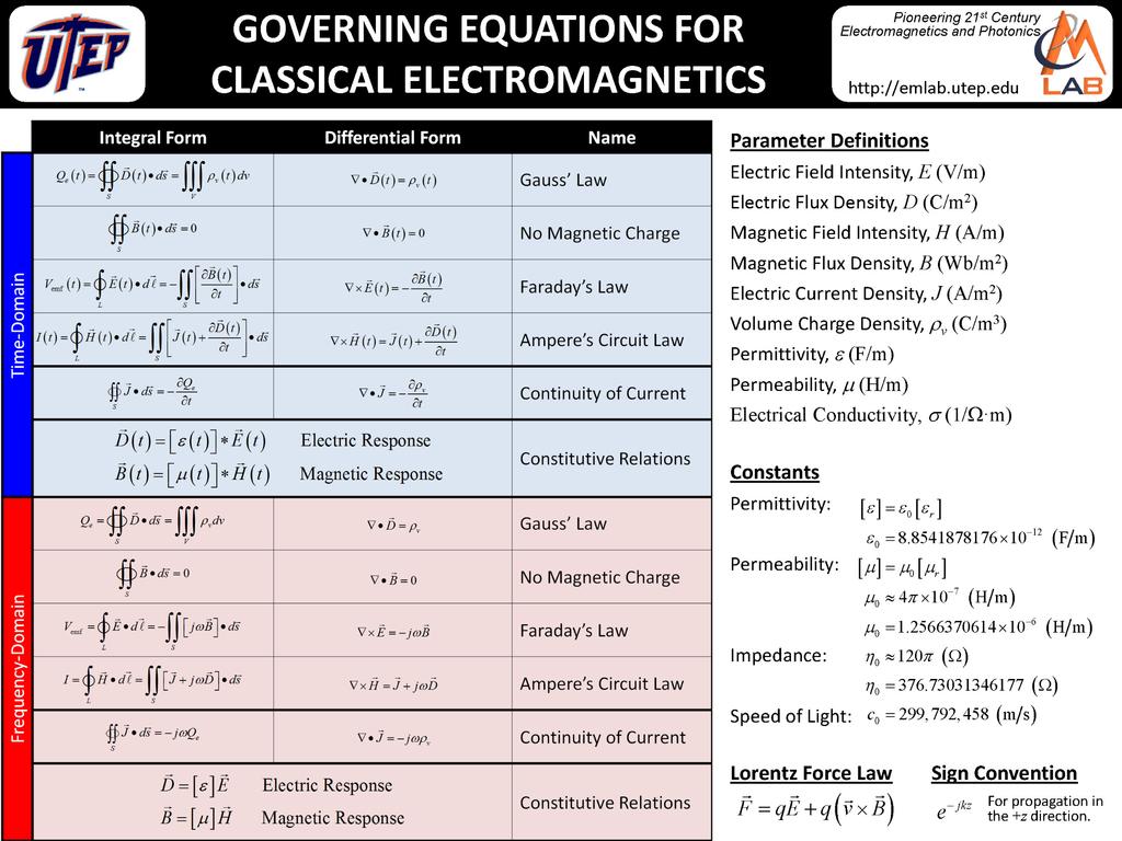
2 Maxwell s Equations Maxwell s Equations
3 All Together Now Divergence Equations B 0 D v Curl Equations D H J t B E t What produces fields Constitutive Relations Dt t Et B t t H t means convolution means tensor How fields interact with materials Lecture 1 Slide 5 Physical Boundary Conditions and 1 1 and Tangential components of E and H are continuous across aninterface. E1,T E,T H1,T H,T Fields normal to the interface are discontinuous across an interface. Note: Normal components of D and B are continuous across the interface. Tangential component of the wave vector is continuous across an interface. 1E1,N 1H1,N E,N H,N k1,t k,t These are more complicated boundary conditions, physically and analytically. Lecture 1 Slide 6 3
.")
4 Wave Vectors and Polarization Wave Vector k A wave vector conveys two pieces of information at the same time. First, its orientation describes the direction of the wave. It is perpendicular to the wave front. Second, its magnitude conveys the spatial period of the wave. It is divided by the spatial period of the wave (wavelength). E r E jk r exp 0 r xxˆ yyˆzzˆ position vector n k 0 k k xˆk yˆk zˆ If the frequency of the wave is known and constant, and x y z it usually is, the magnitude of the k vector conveys the Lecture 1 refractive index of the material the wave is in. Slide 8 k 4
5 The Complex Wave Vector A wave travelling the +z direction can be written in terms of the wave number k as E z E e 0 jkz k k jk Substituting this back into the wave solution yields jk jk z jkz kz E z E0e E0e e oscillation growth/decay Lecture 1 Slide 9 and A wave travelling the +z direction can also be written in terms of a propagation constant and an attenuation coefficient as z j z E z E0 e e growth/decay oscillation We now have physical meaning to the real and imaginary parts of the wave vector. k j k = Re[k] phase term k = Im[k] attenuation term n 0 Lecture 1 Slide 10 5
 Lecture 1 Slide 11 What is Polarization?")
6 1D Waves with Complex k Purely Real k Purely Imaginary k Complex k Uniform amplitude Oscillations move power Considered to be a propagating wave Decaying amplitude No oscillations, no flow of power Considered to be evanescent Decaying amplitude Oscillations move power Considered to be a propagating wave (not evanescent) Lecture 1 Slide 11 What is Polarization? Polarization refers to the orientation of the electric field relative to the direction of the wave. Linear Polarization (LP) Circular Polarization (CP) Left Hand Circular Polarization (LCP) To determine the handedness of CP, imagine watching the electric field in a plane while the wave is coming at you. Which way does it rotate? Lecture 1 Slide 1 6


7 Handedness Convention As Viewed From Source Polarization is taken as the time varying electric field view with the wave moving away from you. Primarily used in engineering and quantum physics. As Viewed From Receiver Polarization is taken as the time varying electric field view with the wave coming toward you. Primarily used in optics and physics. source RCP source RCP receiver receiver source LCP source LCP receiver receiver Lecture 1 Slide 13 Linear Polarization A wave travelling in the +z direction is said to be linearly polarized if: z E x, y, z Pe jk z P sin xˆ cos yˆ P is called the polarization vector. For an arbitrary wave, â E r P a b aˆ bˆ k jk r Pe sin ˆ cos ˆ All components of P have equal phase. ˆb k k Lecture 1 Slide 14 7

8 Circular Polarization A wave travelling in the +z direction is said to be linearly polarized if: z E x, y, z Pe jk z P x jy ˆ ˆ P is called the polarization vector. For an arbitrary wave, jk r Er Pe Paˆ jbˆ aˆ bˆ k The two components of P have equal amplitude and are 90 out of phase. LCP j j RCP k k Lecture 1 Slide 15 Summary In general, a wave travelling in the +z direction can be written as j j x y j z Ex, y, ze ˆ ˆ xe x Eye ye 1 j j x y j z Hx, y, z E ˆ ˆ xe x Eye ye LP x LP y RCP LCP Elliptical E x and E y E y = 0 E x = 0 E x =E y =E R E x =E y =E L E y = E R E L RH: E R >E L E x = E R + E L LH: E R <E L x y 0 0 -/ +/ Lecture 1 Slide 16 8

9 LP x + LP y = LP 45 A linearly polarized wave can always be decomposed as the sum of two orthogonal linearly polarized waves that are in phase. Lecture 1 Slide 17 LP x + jlp y = CP A circularly polarized wave is the sum of two linearly polarized waves that are 90 out of phase. Lecture 1 Slide 18 9


10 RCP + LCP = LP A linearly polarized wave can be expressed as the sum of a LCP wave and a RCP wave. The phase between the two CP waves determines the tilt of the LP. Lecture 1 Slide 19 Why is Polarization Important? Different polarizations can behave differently in a device Orthogonal polarizations will not interfere with each other Polarization becomes critical when analyzing devices on the scale of a wavelength Focusing properties are different Reflection/transmission can be different Frequency of resonators Cutoff conditions for filters, waveguides, etc. Lecture 1 Slide 0 10


11 Poincaré Sphere The polarization of a wave can be mapped to a unique point on the Poincaré sphere. Points on opposite sides of the sphere are orthogonal. See Balanis, Chap LP RCP 90 LP 0 LP +45 LP Lecture 1 Slide 1 LCP TE and TM We use the labels TE and TM when we are describing the orientation of a linearly polarized wave relative to a device. TE/perpendicular/s the electric field is polarized perpendicular to the plane of incidence. TM/parallel/p the electric field is polarized parallel to the plane of incidence. Lecture 1 Slide 11
12 CAUTION: Another Place You Will See TE and TM Labels The labels TE and TM are also used to describe modes in homogeneous metallic waveguides. There really is no comparing TE and TM waveguide modes to TE and TM plane waves incident on a interface. It is a completely different concept. TE 10 TE 01 TE 0 TE 30 TE 11 TM 11 TE 1 TM 1 Lecture 1 Slide 3 Scattering at an Interface 1

13 Reflection, Transmission and Refraction at an Interface Angles inc ref 1 n sin n sin 1 1 Snell s Law Lecture 1 n, 1 1 n, TE Polarization r t 1r TE TE TE cos11cos cos cos 1 1 cos1 cos cos t 1 1 TE TM Polarization r t 1r TM TM TM cos 1cos1 cos cos 1 1 cos1 cos cos 1 1 cos t cos TM 1 Slide 5 Simplifications at Normal Incidence For normal incidence, we have inc ref 1 0 In isotropic materials, the different polarizations reflect and transmit the same. 1 r rt E rtm 1 t tte ttm 1 R r n T n 1 t It really does not make sense to talk about TE and TM for normal incidence because there is no plane of incidence from which to define it. All polarizations scatter the same. 1r t This is NOT conservation of energy because these are field amplitude quantities, not power quantities. Lecture 1 Slide 6 13
14 The Critical Angle (Total Reflection) Above the critical angle c, reflection is 100% r r TE TM cosc 1cos 1 cos cos c 1 cos 1cosc cos cos 1 c 1 This will happen when cos( ) is imaginary. These conditions are derived from Snell s Law. n1 cos 1sin 1 sin c n n sin 1 1 c n1 n cos sin n n 1 1 c n sin c 1 sin n n sin n sin 1 c 1 c n1 Lecture 1 Slide 7 Brewster s Angle (Total Transmission) TE Polarization cosb 1cos rte 0 cos cos B 1 sin 1 1 B We see that as long as 1 = then there is no Brewster s angle. Generally, most materials have a very week magnetic response and there is no Brewster s angle for TE polarized waves. TM Polarization cos 1cos1 rtm 0 cos cos 1 1 sin 1 1 B We see that if 1 = then there is no Brewster s angle. For materials with no magnetic response, the Brewster s angle equation reduces to tan Lecture 1 n This is the most well known equation. B 1 1 n1 Slide 8 14
15 Notes on a Single Interface It is a change in impedance that causes reflections Snell s Law quantifies the angle of transmission Angle of transmission and reflection does not depend on polarization. The Fresnell equations quantify the amount of reflection and transmission Amount of reflection and transmission depends on the polarization For incident angles greater than the critical angle, a wave will be completely reflected regardless of its polarization. When a wave is incident at the Brewster s angle, a particular polarization will be completely transmitted. Lecture 1 Slide 9 Validity of Law of Reflection and Snell s Law There are no plane wave sources. Beam sources are more realistic. A beam can be decomposed into a plane wave spectrum. The Fresnel equations predict that each of the component plane wave will reflect and transmit with a different amplitude depending on its angle and polarization. This means that the amplitude profile of a beam will be modified after reflection and transmission. ref??? inc If the amplitude profile is modified, then the beam will propagate and diffract differently.??? n sin n sin 1 1 This ultimately means the reflected and transmitted beams will propagate at different angles than the law of reflection and Snell s law predict. Lecture


16 More Accurate Picture of Reflection and Transmission temporarily a surface wave Lecture 1 31 Simulation Example A Gaussian beam 5 0 wide is incident from air onto glass with n = 1.5. theoretical modeled inc ref trn inc ref trn inc ref trn 60?? Lecture

17 Scattering from Multiple Interfaces Reflection and Transmission from a Slab incident n ref, ref n, n trn, trn These add together to be the total reflection. These add together to be the total transmission. r re r 1 jk0nl 1 jk0nl rre 1 trn r r ref 1 ref Lecture 1 trn L For small reflections, r r re 1 jk0nl Slide 34 17


18 The Fabry-Perot Cavity Linear Response Low Finesse R R 4% 1 L 5 T R R T FP FP R1R 1 A RR 1 1 A cos 1RR RR cos TT 1 1 RR RR cos Linear Response High Finesse R R 67% 1 L 5 R T R reflectance at first interface 1 R reflectance at second interface T 1R transmittance at first interface 1 1 T 1R transmittance at second interface A power loss through cavity round trip phase shift in the cavity Lecture 1 For small reflections, R T FP FP R 1 cos 1R 1cos Slide 35 Anti-Reflection Coatings n1, 1 n, n, ar ar n1, 1 n, L Lecture 1 General Case ar 1 0 L 4n ar n nn ar 1 0 L 4n ar No magnetic response Slide 36 18
19 Bragg Gratings LH n H L L nl LH n H LL nl LH n H A Bragg grating is typically composed of alternating layers of high and low refractive index. Each layer is /4 thick. Higher index contrast provides wider stop band. More layers improves suppression in the stop band. LL nl L H n H LL nl B LL 4nL B LH 4n Bragg center wavelength B H stop band B Lecture 1 Slide 37 Multilayer Filters in d 1 d d3 d d5 4 d d For small reflection coefficients, the overall reflection coefficient can be written as e e e j j4 jm in 0 1 M where i is the reflection coefficient at the i th interface. Z i Z Z Z i1 i i1 i i1 i i1 i d d We can design any filter response we want by appropriate selection of s and incorporating enough segments. The design process is essentially the same as for designing digital filters. 1 1 M M Lecture 1 Slide 38 19
 and the wave number k (number of oscillations per unit distance).")
20 Phase, Group, and Energy Velocity Phase Velocity The phase velocity of a wave is the speed at which the phase of a single frequency wave propagates through space. It is defined in terms of the angular frequency (number of oscillations per unit time) and the wave number k (number of oscillations per unit distance). v p k Lecture
21 Derivation of Phase Velocity We start with the expression for a wave travelling in the x direction. ; sin E zt kx t kx t 0 kx t x t k x vp t k Wave moves at a speed that keeps the argument of the sine function constant. We set the argument equal to zero and rearrange the terms. This has units of distance/time, which is velocity. We derived this from the phase of the wave sin(). Lecture 1 41 Phase Refractive Index We can characterize a medium by it phase refractive index n p. This is the factor describing how much slower than the speed of light that the phase is propagating. v p c n 0 p Lecture 1 4 1

22 Phase Velocity Can Approach Infinity in a Waveguide (1 of ) A low order mode can be thought of as the sum of two plane waves at small angles relative to the longitudinal direction of the waveguide. Phase propagates slowly. Lecture 1 43 Phase Velocity Can Approach Infinity in a Waveguide ( of ) A high order mode can be thought of as the sum of two plane waves at large angles relative to the longitudinal direction of the waveguide. Phase propagates quickly. Lecture 1 44

23 Group Velocity The group velocity is the speed and direction in which the envelope of the wave s amplitude propagates. It is defined as Here, the wave appears to be very fast, but the overall package of energy propagate slowly. v g k Lecture 1 45 Group Refractive Index We can characterize a medium by it group refractive index n g. This is the factor describing how much slower than the speed of light that the envelop of the wave is propagating. v g c n 0 g Lecture
24 Phase Vs. Group Velocity By their definitions, the phase velocity applies only to a wave at a single frequency. The group velocity applies to a packet of waves covering some spectrum. The phase and group velocities are often the same, but they can be different. Lecture 1 47 Derivation of Group Velocity (1 of 7) By definition, group velocity applies to a wave composed of more than one frequency. A wave composed of two frequencies can be written as ; sin sin E zt kx 1 1t kx t Wave 1 Wave Lecture
25 Derivation of Group Velocity ( of 7) Using the following identity from trigonometry, A B AB sin Asin Bsin cos we get ; sin 1 1 sin kx tkxt kx tkxt E z t k x t k x t sin cos k k1 1 k k1 1 sin x t cos x t Lecture 1 49 Derivation of Group Velocity (3 of 7) The last equation can be written in terms of the center frequency c and the bandwidth. ; sin cos E z t k x t k x t c c k k1 k k1 kc k 1 1 c Lecture
26 Derivation of Group Velocity (4 of 7) We interpret this as a sine wave at frequency c and wave number k c that is modulated by a cosine function. ; sin cos E zt kx t k x t c c Lecture 1 51 Derivation of Group Velocity (5 of 7) We have identified the cos(kx - t) term as the envelope. How quickly does this move? It moves at a speed that keeps the argument of the cosine function constant. kx t constant Lecture 1 5 6
27 Derivation of Group Velocity (6 of 7) To derive a velocity term (dx/dt), we differentiate this equation. kx t 0 kdx dt 0 The equation can now be manipulated to derive a quantity with units of velocity. kdx dt 0 kdx dt dx dt k v dx dt k Lecture 1 53 Derivation of Group Velocity (7 of 7) We now take the limit as the deltas become very small. v g lim 0 k0 k d dk The equivalent equation in more than one dimension is v g k k k dispersion relation Lecture
28 Ordinary Materials In an ordinary material, the dispersion relation is c0 n k The phase velocity is c0 vp n The group velocity is v g d c0 dk n or c k n 0 k We see that the phase velocity and group velocity are equal. When are they not equal? Lecture 1 55 Dispersive Materials (1 of ) In a dispersive material, the refractive index n can be different at different frequencies. We differentiate the dispersion relation as follows. n c0k dn nd c dk We rearrange the terms to arrive at c0 dn d n n dk dk 0 This is group velocity, v g This is phase velocity, v p Lecture
29 Dispersive Materials ( of ) We now have an expression relating group and phase velocity. v p dn v ndk g Solving this for group velocity yields dn k dn vg vp vp1 ndk ndk k We see it is the dn/dk term that is responsible for v g v p. Any time the refractive index n is not constant, the medium is said to have dispersion and the group velocity will deviate from the phase velocity. Lecture 1 57 v p Phase and Group Refractive Indices From the previous equations we can write the phase refractive index n p and group refractive index n g as n p kc0 n g dn p np d dnp np 0 d 0 Lecture
30 Summary of Phase, Group and Energy Velocity Phase Velocity Phase velocity describes the speed and direction of the phase of a wave. v ˆ p s c 0 np k v Group Velocity Group velocity describes the speed and direction of the envelope of a pulse. c0 vg k k ng vg v v no dispersion g p Energy Velocity Energy velocity describes the speed and direction of the energy. P c0 ve ne U ve v v p linear materials Lecture 1 e g Slide 59 k y ŝ k v g v p k x Lenses Lecture 1 Slide 60 30


31 Lenses Lenses are structures that focus electromagnetic waves. Lenses are also used to collimate a beam or diverge a beam. Optical Lens Microwave Lens W. Chalodhorn, D. R. Deboer, Use of Microwave Lenses in Phase Retrieval Microwave Holography of Reflector Antennas, IEEE Trans. Ant. Prop., vol. 50, no. 9, pp , 00. Lecture 1 Slide 61 Ray Tracing Ray tracing is a graphical technique to determine the direction of a beam that passes through the lens. Lecture 1 Slide 6 31
32 Ray Tracing Definitions Thin lens focal plane focal plane focal point optical axis focal point Lecture 1 Slide 63 Ray Tracing: Rule #1 The direction of a ray passing through the center of the lens remains unchanged. Lecture 1 Slide 64 3
33 Ray Tracing: Rule # A ray parallel to the optical axis will pass through the focal point. Lecture 1 Slide 65 Ray Tracing: Rule #3 An arbitrary ray will pass through the focal plane at the same point as a parallel ray passing through the center of the lens. Lecture 1 Slide 66 33


34 Lens s Makers Formula The focal length of a thin lens is approximately 1 nl ens n F n0 R1 R R R 1 F F Lecture 1 Slide 67 Death Rays From a Skyscraper The curved glass on a skyscraper in London acts like a lens. In late August / early September, the sun is at just the right angle to focus light down onto the street. Here, it melted part of an expensive Jaguar. 0 Fenchurch Street, London. Lecture 1 Slide 68 34
35 Gaussian Beams Lecture 1 Slide 69 Ray Matrix A ray matrix relates the height and slope of the input and output rays of an optical system. x, y h A Bh1 C D 1 Ray Matrix h 1 h 1 z Optical System Lecture
36 Common Ray Matrices Unperturbed Distance Thin Lens 1 d f 1 d z f f z 1 1 Lecture 1 71 Combining Ray Matrices Ray matrices are combined using standard matrix multiplication. A C B D A B C D = A C B D A3 B3 A BA1 B1 C3 D 3 C D C1 D 1 Note the order of these matrices. Distance Distance 1 d1 d1 1 d1 d d 1 d Lens Distance 1 d d f d f 1 1 f 1 d z f f z 1 1 Lecture
37 The Gaussian Beam Equation w 0 r 1 z kr Ex, y, z E0 exp exp j kz tan exp j wz w z z0 Rz amplitude amplitude profile longitudinal phase radial phase w z R z z 0 w0 1 z0 nw 0 0 z z0 z1 z Beam width (radius) Radius of curvature Division between near field and far field. Beam diverges linearly for z > z 0. w z z 0 0 w0 minimum spot size r distance from z-axis r x y Lecture 1 73 Geometry of the Gaussian Beam far field near field x, y x, y far field w z w 1 e 0 z 0 z 0 w 0 z planar wavefront Gaussian beam has circular wavefront planar wavefront Lecture
38 ABCD Law The ABCD law allows us to carry radius of curvature R and beam width w through a system s ray matrix. The ABCD law is q z 1 1 Aq1 z B 1 C D q1 z or Cq z D q z A B q z Here the beam parameters R(z) and w(z) are combined into the complex beam parameter q(z) j q z R z nw z w w1 Lecture 1 75 A C B D R R1 q1 q 38
Electromagnetic Waves & Polarization
 Course Instructor Dr. Raymond C. Rumpf Office: A 337 Phone: (915) 747 6958 E Mail: rcrumpf@utep.edu EE 4347 Applied Electromagnetics Topic 3a Electromagnetic Waves & Polarization Electromagnetic These
EE 5337 Computational Electromagnetics. Preliminary Topics
 Instructor Dr. Raymond Rumpf (915) 747 6958 rcrumpf@utep.edu EE 5337 Computational Electromagnetics Lecture #3 Preliminary Topics Lecture 3These notes may contain copyrighted material obtained under fair
Lecture Outline. Scattering From a Dielectric Slab Anti Reflection Layer Bragg Gratings 8/9/2018. EE 4347 Applied Electromagnetics.
 Course Instructor Dr. Raymond C. Rumpf Office: A 337 Phone: (95) 747 6958 E Mail: rcrumpf@utep.edu EE 4347 Applied Electromagnetics Topic 3k Multiple Scattering Multiple These Scattering notes may contain
Lecture Outline. Scattering at an Interface Sunrises & Sunsets Rainbows Polarized Sunglasses 8/9/2018. EE 4347 Applied Electromagnetics.
 Course Instructor Dr. Raymond C. Rumpf Office: A 337 Phone: (915) 747 6958 E Mail: rcrumpf@utep.edu EE 4347 Applied Electromagnetics Topic 3i Scattering at an Interface: Examples Examples These notes may
Electromagnetic fields and waves
 Electromagnetic fields and waves Maxwell s rainbow Outline Maxwell s equations Plane waves Pulses and group velocity Polarization of light Transmission and reflection at an interface Macroscopic Maxwell
Electromagnetic Properties of Materials Part 2
 ECE 5322 21 st Century Electromagnetics Instructor: Office: Phone: E Mail: Dr. Raymond C. Rumpf A 337 (915) 747 6958 rcrumpf@utep.edu Lecture #3 Electromagnetic Properties of Materials Part 2 Nonlinear
EE485 Introduction to Photonics
 Pattern formed by fluorescence of quantum dots EE485 Introduction to Photonics Photon and Laser Basics 1. Photon properties 2. Laser basics 3. Characteristics of laser beams Reading: Pedrotti 3, Sec. 1.2,
: Imaging Systems Laboratory II. Laboratory 6: The Polarization of Light April 16 & 18, 2002
 151-232: Imaging Systems Laboratory II Laboratory 6: The Polarization of Light April 16 & 18, 22 Abstract. In this lab, we will investigate linear and circular polarization of light. Linearly polarized
Phys 531 Lecture 27 6 December 2005
 Phys 531 Lecture 27 6 December 2005 Final Review Last time: introduction to quantum field theory Like QM, but field is quantum variable rather than x, p for particle Understand photons, noise, weird quantum
16. More About Polarization
 16. More About Polarization Polarization control Wave plates Circular polarizers Reflection & polarization Scattering & polarization Birefringent materials have more than one refractive index A special
Course Secretary: Christine Berber O3.095, phone x-6351,
 IMPRS: Ultrafast Source Technologies Franz X. Kärtner (Umit Demirbas) & Thorsten Uphues, Bldg. 99, O3.097 & Room 6/3 Email & phone: franz.kaertner@cfel.de, 040 8998 6350 thorsten.uphues@cfel.de, 040 8998
Lecture Outline. Maxwell s Equations Predict Waves Derivation of the Wave Equation Solution to the Wave Equation 8/7/2018
 Course Instructor Dr. Raymond C. Rumpf Office: A 337 Phone: (915) 747 6958 E Mail: rcrumpf@utep.edu EE 4347 Applied Electromagnetics Topic 3a Electromagnetic Waves Electromagnetic These notes Waves may
Electromagnetic Theory for Microwaves and Optoelectronics
 Keqian Zhang Dejie Li Electromagnetic Theory for Microwaves and Optoelectronics Second Edition With 280 Figures and 13 Tables 4u Springer Basic Electromagnetic Theory 1 1.1 Maxwell's Equations 1 1.1.1
Chapter 2 Basic Optics
 Chapter Basic Optics.1 Introduction In this chapter we will discuss the basic concepts associated with polarization, diffraction, and interference of a light wave. The concepts developed in this chapter
Waves & Oscillations
 Physics 42200 Waves & Oscillations Lecture 32 Electromagnetic Waves Spring 2016 Semester Matthew Jones Electromagnetism Geometric optics overlooks the wave nature of light. Light inconsistent with longitudinal
Gaussian Beam Optics, Ray Tracing, and Cavities
 Gaussian Beam Optics, Ray Tracing, and Cavities Revised: /4/14 1:01 PM /4/14 014, Henry Zmuda Set 1 Gaussian Beams and Optical Cavities 1 I. Gaussian Beams (Text Chapter 3) /4/14 014, Henry Zmuda Set 1
21. Propagation of Gaussian beams
 1. Propagation of Gaussian beams How to propagate a Gaussian beam Rayleigh range and confocal parameter Transmission through a circular aperture Focusing a Gaussian beam Depth of field Gaussian beams and
S. Blair September 27,
 S. Blair September 7, 010 54 4.3. Optical Resonators With Spherical Mirrors Laser resonators have the same characteristics as Fabry-Perot etalons. A laser resonator supports longitudinal modes of a discrete
Waves. Daniel S. Weile. ELEG 648 Waves. Department of Electrical and Computer Engineering University of Delaware. Plane Waves Reflection of Waves
 Waves Daniel S. Weile Department of Electrical and Computer Engineering University of Delaware ELEG 648 Waves Outline Outline Introduction Let s start by introducing simple solutions to Maxwell s equations
1 ESO's Compact Laser Guide Star Unit Ottobeuren, Germany Beam optics!
 1 ESO's Compact Laser Guide Star Unit Ottobeuren, Germany www.eso.org Introduction Characteristics Beam optics! ABCD matrices 2 Background! A paraxial wave has wavefronts whose normals are paraxial rays.!!
REFLECTION AND REFRACTION OF PLANE EM WAVES
 REFLECTION AND REFRACTION OF PLANE EM WAVES When an electromagnetic wave hits a boundary between different materials, some of the wave s energy is reflected back while the rest continues on through the
Summary of Beam Optics
 Summary of Beam Optics Gaussian beams, waves with limited spatial extension perpendicular to propagation direction, Gaussian beam is solution of paraxial Helmholtz equation, Gaussian beam has parabolic
The science of light. P. Ewart
 The science of light P. Ewart Oxford Physics: Second Year, Optics Parallel reflecting surfaces t images source Extended source path difference xcos 2t=x Fringes localized at infinity Circular fringe constant
Polarization Mode Dispersion
 Unit-7: Polarization Mode Dispersion https://sites.google.com/a/faculty.muet.edu.pk/abdullatif Department of Telecommunication, MUET UET Jamshoro 1 Goos Hänchen Shift The Goos-Hänchen effect is a phenomenon
EM waves and interference. Review of EM wave equation and plane waves Energy and intensity in EM waves Interference
 EM waves and interference Review of EM wave equation and plane waves Energy and intensity in EM waves Interference Maxwell's Equations to wave eqn The induced polarization, P, contains the effect of the
Electromagnetic Theory for Microwaves and Optoelectronics
 Keqian Zhang Dejie Li Electromagnetic Theory for Microwaves and Optoelectronics Translated by authors With 259 Figures Springer Contents 1 Basic Electromagnetic Theory 1 1.1 Maxwell's Equations 1 1.1.1
1 The formation and analysis of optical waveguides
 1 The formation and analysis of optical waveguides 1.1 Introduction to optical waveguides Optical waveguides are made from material structures that have a core region which has a higher index of refraction
Lecture 36 Date:
 Lecture 36 Date: 5.04.04 Reflection of Plane Wave at Oblique Incidence (Snells Law, Brewster s Angle, Parallel Polarization, Perpendicular Polarization etc.) Introduction to RF/Microwave Introduction One
IMPRS: Ultrafast Source Technologies
 IMPRS: Ultrafast Source Technologies Fran X. Kärtner & Thorsten Uphues, Bldg. 99, O3.097 & Room 6/3 Email & phone: fran.kaertner@cfel.de, 040 8998 6350 Thorsten.Uphues@cfel.de, 040 8998 706 Lectures: Tuesday
34. Even more Interference Effects
 34. Even more Interference Effects The Fabry-Perot interferometer Thin-film interference Anti-reflection coatings Single- and multi-layer Advanced topic: Photonic crystals Natural and artificial periodic
PRINCIPLES OF PHYSICAL OPTICS
 PRINCIPLES OF PHYSICAL OPTICS C. A. Bennett University of North Carolina At Asheville WILEY- INTERSCIENCE A JOHN WILEY & SONS, INC., PUBLICATION CONTENTS Preface 1 The Physics of Waves 1 1.1 Introduction
Laser Optics-II. ME 677: Laser Material Processing Instructor: Ramesh Singh 1
 Laser Optics-II 1 Outline Absorption Modes Irradiance Reflectivity/Absorption Absorption coefficient will vary with the same effects as the reflectivity For opaque materials: reflectivity = 1 - absorptivity
Topic 4: Waves 4.3 Wave characteristics
 Guidance: Students will be expected to calculate the resultant of two waves or pulses both graphically and algebraically Methods of polarization will be restricted to the use of polarizing filters and
Lecture Outline. Dispersion Relation Electromagnetic Wave Polarization 8/7/2018. EE 4347 Applied Electromagnetics. Topic 3c
 Course Instructor Dr. Rymond C. Rumpf Office: A 337 Phone: (915) 747 6958 E Mil: rcrumpf@utep.edu EE 4347 Applied Electromgnetics Topic 3c Wve Dispersion & Polriztion Wve Dispersion These notes & Polriztion
Edward S. Rogers Sr. Department of Electrical and Computer Engineering. ECE318S Fundamentals of Optics. Final Exam. April 16, 2007.
 Edward S. Rogers Sr. Department of Electrical and Computer Engineering ECE318S Fundamentals of Optics Final Exam April 16, 2007 Exam Type: D (Close-book + two double-sided aid sheets + a non-programmable
Optics for Engineers Chapter 9
 Optics for Engineers Chapter 9 Charles A. DiMarzio Northeastern University Nov. 202 Gaussian Beams Applications Many Laser Beams Minimum Uncertainty Simple Equations Good Approximation Extensible (e.g.
ECE 484 Semiconductor Lasers
 ECE 484 Semiconductor Lasers Dr. Lukas Chrostowski Department of Electrical and Computer Engineering University of British Columbia January, 2013 Module Learning Objectives: Understand the importance of
EITN90 Radar and Remote Sensing Lecture 5: Target Reflectivity
 EITN90 Radar and Remote Sensing Lecture 5: Target Reflectivity Daniel Sjöberg Department of Electrical and Information Technology Spring 2018 Outline 1 Basic reflection physics 2 Radar cross section definition
Optics for Engineers Chapter 9
 Optics for Engineers Chapter 9 Charles A. DiMarzio Northeastern University Mar. 204 Gaussian Beams Applications Many Laser Beams Minimum Uncertainty Simple Equations Good Approximation Extensible (e.g.
Electromagnetic Waves Across Interfaces
 Lecture 1: Foundations of Optics Outline 1 Electromagnetic Waves 2 Material Properties 3 Electromagnetic Waves Across Interfaces 4 Fresnel Equations 5 Brewster Angle 6 Total Internal Reflection Christoph
Wavepackets. Outline. - Review: Reflection & Refraction - Superposition of Plane Waves - Wavepackets - ΔΔk Δx Relations
 Wavepackets Outline - Review: Reflection & Refraction - Superposition of Plane Waves - Wavepackets - ΔΔk Δx Relations 1 Sample Midterm (one of these would be Student X s Problem) Q1: Midterm 1 re-mix (Ex:
Optics, Optoelectronics and Photonics
 Optics, Optoelectronics and Photonics Engineering Principles and Applications Alan Billings Emeritus Professor, University of Western Australia New York London Toronto Sydney Tokyo Singapore v Contents
Polarizers and Retarders
 Phys 531 Lecture 20 11 November 2004 Polarizers and Retarders Last time, discussed basics of polarization Linear, circular, elliptical states Describe by polarization vector ĵ Today: Describe elements
Chapter 1 - The Nature of Light
 David J. Starling Penn State Hazleton PHYS 214 Electromagnetic radiation comes in many forms, differing only in wavelength, frequency or energy. Electromagnetic radiation comes in many forms, differing
POLARIZATION OF LIGHT
 POLARIZATION OF LIGHT OVERALL GOALS The Polarization of Light lab strongly emphasizes connecting mathematical formalism with measurable results. It is not your job to understand every aspect of the theory,
Radio Propagation Channels Exercise 2 with solutions. Polarization / Wave Vector
 /8 Polarization / Wave Vector Assume the following three magnetic fields of homogeneous, plane waves H (t) H A cos (ωt kz) e x H A sin (ωt kz) e y () H 2 (t) H A cos (ωt kz) e x + H A sin (ωt kz) e y (2)
Fourier Approach to Wave Propagation
 Phys 531 Lecture 15 13 October 005 Fourier Approach to Wave Propagation Last time, reviewed Fourier transform Write any function of space/time = sum of harmonic functions e i(k r ωt) Actual waves: harmonic
The individual electric and magnetic waves are in phase. The fields peak at the same position at the same time.
 1 Part 3: Otics 3.1: Electromagnetic Waves An electromagnetic wave (light wave) consists of oscillating electric and magnetic fields. The directions of the electric and magnetic fields are erendicular.
Lecture 9. Transmission and Reflection. Reflection at a Boundary. Specific Boundary. Reflection at a Boundary
 Lecture 9 Reflection at a Boundary Transmission and Reflection A boundary is defined as a place where something is discontinuous Half the work is sorting out what is continuous and what is discontinuous
Light.notebook May 03, 2016
 Unit 4 Light LIGHT.1 Describe the ray model of light. 16.1 LIGHT.2 Predict the effect of distance on light s illuminance. 16.1 LIGHT.3 Explain polarization and the Doppler effect. 16.2 LIGHT.4 Describe
1. Consider the biconvex thick lens shown in the figure below, made from transparent material with index n and thickness L.
 Optical Science and Engineering 2013 Advanced Optics Exam Answer all questions. Begin each question on a new blank page. Put your banner ID at the top of each page. Please staple all pages for each individual
Chap. 1 Fundamental Concepts
 NE 2 Chap. 1 Fundamental Concepts Important Laws in Electromagnetics Coulomb s Law (1785) Gauss s Law (1839) Ampere s Law (1827) Ohm s Law (1827) Kirchhoff s Law (1845) Biot-Savart Law (1820) Faradays
Vector diffraction theory of refraction of light by a spherical surface
 S. Guha and G. D. Gillen Vol. 4, No. 1/January 007/J. Opt. Soc. Am. B 1 Vector diffraction theory of refraction of light by a spherical surface Shekhar Guha and Glen D. Gillen* Materials and Manufacturing
3.5 Cavities Cavity modes and ABCD-matrix analysis 206 CHAPTER 3. ULTRASHORT SOURCES I - FUNDAMENTALS
 206 CHAPTER 3. ULTRASHORT SOURCES I - FUNDAMENTALS which is a special case of Eq. (3.30. Note that this treatment of dispersion is equivalent to solving the differential equation (1.94 for an incremental
Lecture 19 Optical MEMS (1)
") EEL6935 Advanced MEMS (Spring 5) Instructor: Dr. Huikai Xie Lecture 19 Optical MEMS (1) Agenda: Optics Review EEL6935 Advanced MEMS 5 H. Xie 3/8/5 1 Optics Review Nature of Light Reflection and Refraction
EEL6935 Advanced MEMS (Spring 5) Instructor: Dr. Huikai Xie Lecture 19 Optical MEMS (1) Agenda: Optics Review EEL6935 Advanced MEMS 5 H. Xie 3/8/5 1 Optics Review Nature of Light Reflection and Refraction
Waves in Linear Optical Media
 1/53 Waves in Linear Optical Media Sergey A. Ponomarenko Dalhousie University c 2009 S. A. Ponomarenko Outline Plane waves in free space. Polarization. Plane waves in linear lossy media. Dispersion relations
Notes on Huygens Principle 2000 Lawrence Rees
 Notes on Huygens Principle 2000 Lawrence Rees In the 17 th Century, Christiaan Huygens (1629 1695) proposed what we now know as Huygens Principle. We often invoke Huygens Principle as one of the fundamental
PH 222-2C Fall Electromagnetic Waves Lectures Chapter 33 (Halliday/Resnick/Walker, Fundamentals of Physics 8 th edition)
") PH 222-2C Fall 2012 Electromagnetic Waves Lectures 21-22 Chapter 33 (Halliday/Resnick/Walker, Fundamentals of Physics 8 th edition) 1 Chapter 33 Electromagnetic Waves Today s information age is based almost
PH 222-2C Fall 2012 Electromagnetic Waves Lectures 21-22 Chapter 33 (Halliday/Resnick/Walker, Fundamentals of Physics 8 th edition) 1 Chapter 33 Electromagnetic Waves Today s information age is based almost
3. Maxwell's Equations and Light Waves
 3. Maxwell's Equations and Light Waves Vector fields, vector derivatives and the 3D Wave equation Derivation of the wave equation from Maxwell's Equations Why light waves are transverse waves Why is the
Optics and Optical Design. Chapter 6: Polarization Optics. Lectures 11 13
 Optics and Optical Design Chapter 6: Polarization Optics Lectures 11 13 Cord Arnold / Anne L Huillier Polarization of Light Arbitrary wave vs. paraxial wave One component in x direction y x z Components
Lab #13: Polarization
 Lab #13: Polarization Introduction In this experiment we will investigate various properties associated with polarized light. We will study both its generation and application. Real world applications
PLANE WAVE PROPAGATION AND REFLECTION. David R. Jackson Department of Electrical and Computer Engineering University of Houston Houston, TX
 PLANE WAVE PROPAGATION AND REFLECTION David R. Jackson Department of Electrical and Computer Engineering University of Houston Houston, TX 7704-4793 Abstract The basic properties of plane waves propagating
Lecture 5: Polarization. Polarized Light in the Universe. Descriptions of Polarized Light. Polarizers. Retarders. Outline
 Lecture 5: Polarization Outline 1 Polarized Light in the Universe 2 Descriptions of Polarized Light 3 Polarizers 4 Retarders Christoph U. Keller, Leiden University, keller@strw.leidenuniv.nl ATI 2016,
Wave Propagation in Uniaxial Media. Reflection and Transmission at Interfaces
 Lecture 5: Crystal Optics Outline 1 Homogeneous, Anisotropic Media 2 Crystals 3 Plane Waves in Anisotropic Media 4 Wave Propagation in Uniaxial Media 5 Reflection and Transmission at Interfaces Christoph
Light as a Transverse Wave.
 Waves and Superposition (Keating Chapter 21) The ray model for light (i.e. light travels in straight lines) can be used to explain a lot of phenomena (like basic object and image formation and even aberrations)
Digital Holographic Measurement of Nanometric Optical Excitation on Soft Matter by Optical Pressure and Photothermal Interactions
 Ph.D. Dissertation Defense September 5, 2012 Digital Holographic Measurement of Nanometric Optical Excitation on Soft Matter by Optical Pressure and Photothermal Interactions David C. Clark Digital Holography
Electromagnetic Waves
 Electromagnetic Waves As the chart shows, the electromagnetic spectrum covers an extremely wide range of wavelengths and frequencies. Though the names indicate that these waves have a number of sources,
Electromagnetic Waves
 Electromagnetic Waves Maxwell s equations predict the propagation of electromagnetic energy away from time-varying sources (current and charge) in the form of waves. Consider a linear, homogeneous, isotropic
Synthesizing Geometries for 21st Century Electromagnetics
 ECE 5322 21 st Century Electromagnetics Instructor: Office: Phone: E Mail: Dr. Raymond C. Rumpf A 337 (915) 747 6958 rcrumpf@utep.edu Lecture #18b Synthesizing Geometries for 21st Century Electromagnetics
3/9/2011. Outline Chapter 7 Waves Water Waves Water Waves. Water waves are really circular. They are an example of Mechanical waves.
 Outline Chapter 7 Waves 7-1. Water Waves 7-2. Transverse and Longitudinal Waves 7-3. Describing Waves 7-4. Standing Waves 7-5. Sound 7-6. Doppler Effect 7-7. Musical Sounds 7-8. Electromagnetic Waves 7-9.
Lecture Notes on Wave Optics (03/05/14) 2.71/2.710 Introduction to Optics Nick Fang
 2.71/2.710 Introduction to Optics Nick Fang") Outline: A. Electromagnetism B. Frequency Domain (Fourier transform) C. EM waves in Cartesian coordinates D. Energy Flow and Poynting Vector E. Connection to geometrical optics F. Eikonal Equations: Path
Outline: A. Electromagnetism B. Frequency Domain (Fourier transform) C. EM waves in Cartesian coordinates D. Energy Flow and Poynting Vector E. Connection to geometrical optics F. Eikonal Equations: Path
UNIT-5 EM WAVES UNIT-6 RAY OPTICS
 UNIT-5 EM WAVES 2 Marks Question 1. To which regions of electromagnetic spectrum do the following wavelengths belong: (a) 250 nm (b) 1500 nm 2. State any one property which is common to all electromagnetic
Lecture #16. Spatial Transforms. Lecture 16 1
 ECE 53 1 st Century Electromagnetics Instructor: Office: Phone: E Mail: Dr. Raymond C. Rumpf A 337 (915) 747 6958 rcrumpf@utep.edu Lecture #16 Spatial ransforms Lecture 16 1 Lecture Outline ransformation
Dispersion and how to control it
 Dispersion and how to control it Group velocity versus phase velocity Angular dispersion Prism sequences Grating pairs Chirped mirrors Intracavity and extra-cavity examples 1 Pulse propagation and broadening
Experiment 6: Interferometers
 Experiment 6: Interferometers Nate Saffold nas2173@columbia.edu Office Hour: Mondays, 5:30PM-6:30PM @ Pupin 1216 INTRO TO EXPERIMENTAL PHYS-LAB 1493/1494/2699 NOTE: No labs and no lecture next week! Outline
Lecture 11: Introduction to diffraction of light
 Lecture 11: Introduction to diffraction of light Diffraction of waves in everyday life and applications Diffraction in everyday life Diffraction in applications Spectroscopy: physics, chemistry, medicine,
Lecture 9: Introduction to Diffraction of Light
 Lecture 9: Introduction to Diffraction of Light Lecture aims to explain: 1. Diffraction of waves in everyday life and applications 2. Interference of two one dimensional electromagnetic waves 3. Typical
Propagation of EM Waves in material media
 Propagation of EM Waves in material media S.M.Lea 09 Wave propagation As usual, we start with Maxwell s equations with no free charges: D =0 B =0 E = B t H = D t + j If we now assume that each field has
FIRST YEAR PHYSICS. Unit 4: Light II
 FIRST YEAR PHYSICS Unit 4: Light II Contents PHASORS...3 RESOLUTION OF OPTICAL INSTRUMENTS...5 Rayleigh s criterion... 7 MORE ON DIFFRACTION...11 Multiple slits:... 11 Diffraction gratings... 14 X-RAY
PHYS 408, Optics. Problem Set 4 - Spring Posted: Fri, March 4, 2016 Due: 5pm Thu, March 17, 2016
 PHYS 408, Optics Problem Set 4 - Spring 06 Posted: Fri, March 4, 06 Due: 5pm Thu, March 7, 06. Refraction at a Spherical Boundary. Derive the M matrix of.4-6 in the textbook. You may use Snell s Law directly..
General Appendix A Transmission Line Resonance due to Reflections (1-D Cavity Resonances)
") A 1 General Appendix A Transmission Line Resonance due to Reflections (1-D Cavity Resonances) 1. Waves Propagating on a Transmission Line General A transmission line is a 1-dimensional medium which can
A 1 General Appendix A Transmission Line Resonance due to Reflections (1-D Cavity Resonances) 1. Waves Propagating on a Transmission Line General A transmission line is a 1-dimensional medium which can
Brewster Angle and Total Internal Reflection
 Lecture 4: Polarization Outline 1 Polarized Light in the Universe 2 Brewster Angle and Total Internal Reflection 3 Descriptions of Polarized Light 4 Polarizers 5 Retarders Christoph U. Keller, Utrecht
Electromagnetic Wave Propagation Lecture 3: Plane waves in isotropic and bianisotropic media
 Electromagnetic Wave Propagation Lecture 3: Plane waves in isotropic and bianisotropic media Daniel Sjöberg Department of Electrical and Information Technology September 2016 Outline 1 Plane waves in lossless
Physics 214 Course Overview
 Physics 214 Course Overview Lecturer: Mike Kagan Course topics Electromagnetic waves Optics Thin lenses Interference Diffraction Relativity Photons Matter waves Black Holes EM waves Intensity Polarization
Einstein Classes, Unit No. 102, 103, Vardhman Ring Road Plaza, Vikas Puri Extn., Outer Ring Road New Delhi , Ph. : ,
 1 O P T I C S 1. Define resolving power of a telescope & microscope and give the expression for its resolving power. 2. Explain briefly the formation of mirage in deserts. 3. The radii of curvature of
Calculating Thin Film Stack Properties
 Lecture 5: Thin Films Outline 1 Thin Films 2 Calculating Thin Film Stack Properties 3 Fabry-Perot Tunable Filter 4 Anti-Reflection Coatings 5 Interference Filters Christoph U. Keller, Leiden University,
Interference, Diffraction and Fourier Theory. ATI 2014 Lecture 02! Keller and Kenworthy
 Interference, Diffraction and Fourier Theory ATI 2014 Lecture 02! Keller and Kenworthy The three major branches of optics Geometrical Optics Light travels as straight rays Physical Optics Light can be
Brewster Angle and Total Internal Reflection
 Lecture 5: Polarization Outline 1 Polarized Light in the Universe 2 Brewster Angle and Total Internal Reflection 3 Descriptions of Polarized Light 4 Polarizers 5 Retarders Christoph U. Keller, Leiden University,
APPLICATION OF BILAYER ANISOTROPIC STRUC- TURES FOR DESIGNING LOW-PASS FILTERS AND PO- LARIZERS
 Progress In Electromagnetics Research M, Vol. 29, 95 108, 2013 APPLICATION OF BILAYER ANISOTROPIC STRUC- TURES FOR DESIGNING LOW-PASS FILTERS AND PO- LARIZERS Amir Raeesi *, Ali Abdolali, and Hossein Mirzaei
Innovation and Development of Study Field. nano.tul.cz
 Innovation and Development of Study Field Nanomaterials at the Technical University of Liberec nano.tul.cz These materials have been developed within the ESF project: Innovation and development of study
Slow Photons in Vacuum as Elementary Particles. Chander Mohan Singal
 Ref ETOP98 Slow Photons in Vacuum as Elementary Particles Chander Mohan Singal Department of Physics, Indian Institute of Technology-Delhi, Hauz Khas, New Delhi-1116, INDIA E-Mail: drcmsingal@yahoocom
Nature of Light Part 2
 Nature of Light Part 2 Fresnel Coefficients From Helmholts equation see imaging conditions for Single lens 4F system Diffraction ranges Rayleigh Range Diffraction limited resolution Interference Newton
EE485 Introduction to Photonics. Introduction
 EE485 Introduction to Photonics Introduction Nature of Light They could but make the best of it and went around with woebegone faces, sadly complaining that on Mondays, Wednesdays, and Fridays, they must
and the radiation from source 2 has the form. The vector r points from the origin to the point P. What will the net electric field be at point P?
 Physics 3 Interference and Interferometry Page 1 of 6 Interference Imagine that we have two or more waves that interact at a single point. At that point, we are concerned with the interaction of those
Multilayer Reflectivity
 Multilayer Reflectivity John E. Davis jed@jedsoft.org January 5, 2014 1 Introduction The purpose of this document is to present an ab initio derivation of the reflectivity for a plane electromagnetic wave
Basics of electromagnetic response of materials
 Basics of electromagnetic response of materials Microscopic electric and magnetic field Let s point charge q moving with velocity v in fields e and b Force on q: F e F qeqvb F m Lorenz force Microscopic
Generating Bessel beams by use of localized modes
 992 J. Opt. Soc. Am. A/ Vol. 22, No. 5/ May 2005 W. B. Williams and J. B. Pendry Generating Bessel beams by use of localized modes W. B. Williams and J. B. Pendry Condensed Matter Theory Group, The Blackett
Course Updates. 2) This week: Electromagnetic Waves +
 This week: Electromagnetic Waves +") Course Updates http://www.phys.hawaii.edu/~varner/phys272-spr1/physics272.html Reminders: 1) Assignment #11 due Wednesday 2) This week: Electromagnetic Waves + 3) In the home stretch [review schedule]
Course Updates http://www.phys.hawaii.edu/~varner/phys272-spr1/physics272.html Reminders: 1) Assignment #11 due Wednesday 2) This week: Electromagnetic Waves + 3) In the home stretch [review schedule]
Optics and Optical Design. Chapter 6: Polarization Optics. Lectures 11-13
 Optics and Optical Design Chapter 6: Polarization Optics Lectures 11-13 Cord Arnold / Anne L Huillier Polarization of Light Arbitrary wave vs. paraxial wave One component in x-direction y x z Components
Edward S. Rogers Sr. Department of Electrical and Computer Engineering. ECE426F Optical Engineering. Final Exam. Dec. 17, 2003.
 Edward S. Rogers Sr. Department of Electrical and Computer Engineering ECE426F Optical Engineering Final Exam Dec. 17, 2003 Exam Type: D (Close-book + one 2-sided aid sheet + a non-programmable calculator)