Section 6: PRISMATIC BEAMS. Beam Theory
|
|
|
- Stella Barton
- 5 years ago
- Views:
Transcription
1 Beam Theory There are two types of beam theory aailable to craft beam element formulations from. They are Bernoulli-Euler beam theory Timoshenko beam theory One learns the details of Bernoulli-Euler beam theory as undergraduates in a Strength of Materials course. Timoshenko beam theory is used when the effects on deformation from shear is significant. The conditions under which shear deformations can not be ignored are spelled out later in the section in the discussion on strain energy. The deriation for both theories are presented here. Bernoulli-Euler beam theory is discussed first. In the net figure a deformed beam is superimposed on a a beam element represented by a straight line. We represented aial force elements by a line element in a graph that maps deformations in a ery similar manner. Howeer, for a beam element we should be concerned with Aial translations Beam deflections Rotations (bending and torsional)
2 Howeer, in order to deelop the two beam theories torsional rotations and aial translations will be ignored for the moment and the focus will be on effects from beam bending. In the figure below the original position of the centroidal ais coincides with the -ais. The cross sectional area is constant along the length of the beam. A second moment of the cross sectional area with respect to z-ais is identified as I z. The beam is fabricated from a material with a Young s modulus E. Nodes are identified at either end of the beam element. y,
3 The key assumption for Bernoulli-Euler beam theory is that plane sections remain plane and also remain perpendicular to the deformed centroidal ais. The preious figure shows a beam element based on this theory of length,, with transerse end displacements, and, rotation of the end planes θ and θ and rotation of the neutral ais, μ and μ at nodes and. The requirement that cross-sections remain perpendicular to the neutral ais means that Note that d d d d where the sign conention that clockwise rotations are negatie is adopted.
4 Recall from elementary calculus the curature (lowercase Greek letter kappa, ) of a line at a point may be epressed as In the case of an elastic cure rotations are small, thus the deriatie dy/d is small and squaring a small quantity produces something smaller still, thus Gien a prismatic beam subjected to pure bending the curature is When the beam is subjected to transerse loads this equation is still alid proided St. Venant s principle is not iolated. Howeer the bending moment and thus the curature will 4 ary from section to section. d y d dy d d y d M EI
5 Thus And d d M EI M EI In addition d d tan EI M d C The assumption that plane sections remain perpendicular to the centroidal ais necessarily implies that shear strain, γ y, is zero. This in turn implies that shear stress and shear force are zero. The only load case that results in zero shear force is a constant (uniform) bending moment and thus Bernoulli-Euler theory strictly holds only for this case. 5
6 As we will see later Bernoulli-Euler beam theory is acceptable only for long slender beams. Errors incurred in displacements by ignoring shear effects are of the order of (d/), where d is the depth of a beam and is the length. In the case where a beam is relatiely short or deep, shear effects can, howeer, be significant (Timoshenko, 957). The critical difference in Timoshenko theory is that the assumption that plane sections remain plane and perpendicular to the neutral ais is relaed to allow plane sections to undergo a shear strain γ. The plane section still remains plane but rotates by an amount, θ, equal to the rotation of the neutral ais, μ, minus the shear strain γ as shown in the preious figure. The rotation of the cross section is thus Taking deriaties of both sides with respect to leads to d d d d d d d d 6

7 Thus for a Timoshenko beam d d d d M EI where for a Bernoulli-Euler beam d d The differences will come into play when strain energies are computed using one theory or the other. It turns out that a shear correction factor is introduced to the element stiffness matri for a Bernoulli-Euler beam element to obtain the element stiffness matri for a Timoshenko beam element. The issue of short deep beams can arise more often than one might think. For ciil engineers consider a girder supporting a short span in a bridge for a major transportation artery (rail or automotie). Another application would be the use of a short deep beam as a beam seat support. M EI 7

8 8
9 In static analyses the differences between the two theories is not pronounced until the aspect ratio defined as AR Beam length Beam depth or l/h in the figures below, is less than 0. The differences become more pronounced in a ibrations problem. d 9
10 Preliminaries Beam Elements The stiffness matri for any structure is composed of the sum of the stiffnesses of the elements. Once again, we search for a conenient approach to sum the element stiffnesses in some systematic fashion when the structure is a beam. Consider the following prismatic beam element: This element can be from a three-dimensional frame so that all possible forces and moments can be depicted at each node. The member is fully restrained and it is conenient to adopt an orthogonal aes oriented to the member. 0
11 The m -ais is a centroidal ais, the m -y m plane and the m -z m plane are principle planes of bending. We assume that the shear center and the centroid of the member coincide so that twisting and bending are not coupled. The properties of the member are defined in a systematic fashion. The length of the member is, the cross sectional area is A. The principle moments of inertial relatie to the y m and z m aes are I y and I z, respectiely. The torsional constant J (= I y + I z only for a circular cross section, aka, the polar moment of inertia only for this special case) will be designated I in the figures that follow. Beams with non-circular cross sections (structural shapes) will warp when twisted with a torsional moment or when the plane of the applied loads does not pass through the shear center. Restraint at fied ends of a beam will induce both shear stresses and aial normal stresses that are not uniform within the cross section. In addition, these stresses will propagate out from the fied end for a distance that is dependent on the geometry of the cross section. Shape functions typically will not account for this propagation of stresses. To account for out of plane warping an additional degree of freedom must be introduced at each load that corresponds to the rate of twist (dq/d). Typical commercial codes do not account for the degree of freedom. The member stiffnesses for the twele possible types of end displacement are summarized in the net section.
12 Stiffness Matrices for Beams Matri Methods Approach In the stiffness method the unknown quantities are nodal (joint) displacements. Hence, the number of unknowns is equal to the degree of kinematic indeterminacy for the stiffness method. Briefly, the unit load (force or moment) method to determine components of a stiffness matri proceeds as follows: Unknown nodal displacements are identified and structure is restrained Restrained structure is kinematically determinate, i.e., all displacements are zero Stiffness matri is formulated by successiely applying unit loads at the now restrained unknown nodal displacements To demonstrate the approach for beams we first consider a single span beam. This beam is depicted on the following page. Nodes (joints in Matri Methods) are positioned at either end of the beam.
13 y M Actual Beam M Neglecting aial deformations, as well as displacements and rotations in the z M -direction the beam in the first figure to the left is kinematically indeterminate to the first degree. The only unknown is a joint displacement at B, i.e., the rotation at this node. Restrained Beam # Restrained Beam # We alter the beam in the second figure such that it becomes kinematically determinate by making the rotation θ B equal to zero. This is accomplished by making the end B a fied end. This new beam is then called the restrained structure. The beam in the third figure is the restrained structure with the rotation θ B imposed from the original structure. Superposition of restrained beams # and # yields the original beam.
14 Due to the uniform load w the moment in the first restrained structure, i.e., M B M B w In restrained beam # an additional couple at B is deeloped due to the rotation θ B. The additional moment is equal in magnitude but opposite in direction to that on the loaded restrained beam. The alue of this moment is M Imposing equilibrium at the joint B in the superimposed restrained structures B 4EI B is yields M w 4EI B 0 B w 48EI 4
15 There is a way to analyze the preious simple structure through the use of a unit load. The superposition principle can be utilized. Both superposition and the application of a unit load will help deelop a systematic approach to analyzing beam elements as well as structures that hae much higher degrees of kinematic indeterminacy. The effect of a unit rotation on the preious beam is depicted below. The moment applied, m B, will produce a unit rotation at B. Restrained Beam with unit rotation 4EI m B We now somewhat informally define a stiffness coefficient as the action (force or moment) that produces a unit displacement (translation or rotation). 5
16 We now utilize superposition again. The moment in restrained beam # will be added to the moment m B multiplied by the rotation in the actual beam, B. The sum of these two terms must gie the moment in the actual beam, which is zero, i.e., M B m B B 0 or w 4EI B 0 In finite element analysis the first term aboe is an equialent nodal force generated by the distributed load. Soling for B yields once again B w 48EI The positie sign indicates the rotation is counterclockwise. Note that in finite element analysis, B is an unknown displacement (rotation) and m B is a stiffness coefficient for the beam element matri. The beam element is defined by nodes A and B. 6
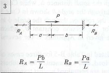
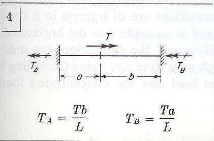
17 Beam Tables Useful Cases The net seeral beam cases will proe useful in establishing components of the stiffness matri. Consult the AISC Steel Design Manual or Roark s tet for many others not found here. 7

18 8
19 9
20 Note that eery eample cited hae fied-fied end conditions. All are kinematically determinate beam elements. 0
21 y M Multiple Degrees of Kinematic Indeterminacy M Consider the beam to the left with a constant fleural rigidity, EI. Since rotations can occur at nodes B as well as C, and we do not know what they are, the structure is kinematically indeterminate to the second degree. Aial displacements as well as displacements and rotations in the z M - direction are neglected. D = D = 0 D = 0 D = Designate the unknown rotations as D (and the associated bending moment from the load applied between nodes as A D ) and D (and bending moment A D from the load between nodes). Assume counterclockwise rotations as positie. The unknown displacements are determined by applying the principle of superposition to the bending moments at joints B and C. Note: D displacement (translation or rotation) A action (force or moment)
22 All loads ecept those corresponding to the unknown joint displacements are assumed to act on the restrained structure. Thus only actions P and P are shown acting on the restrained structure. The moments A D and A D are the actions at the restrained nodes associated with D (A D in Matri Methods, M B, the global moment at node B in Finite Element Analysis) and D (A D in Matri Methods, M C, the global moment at node C in Finite Element Analysis) respectiely. The notation in parenthesis will help with the matri notation momentarily. In addition, numerical subscripts are associated with the unknown nodal displacements, i.e., D and D. These displacements occur at nodes B and C. ater when this approach is generalized eery node will be numbered, not lettered. In addition, the actions in the figure aboe that occur between nodes are subscripted for conenience and these subscripts bear no relationship to the nodes.
23 In order to generate indiidual alues of the beam element stiffness matri, unit alues of the unknown displacements D and D are induced in separately restrained structures. D = In the restrained beam to the left a unit rotation is applied to joint B. The actions (moments) induced in the restrained structure corresponding to D and D are the stiffness coefficients S and S, respectiely D = In the restrained beam to the left a unit rotation is applied to joint B. The actions (moments) induced in this restrained structure corresponding to D and D are the stiffness coefficients S and S, respectiely All the stiffness coefficients in the figures hae two subscripts (S ij ). The first subscript identifies the location of the action induced by the unit displacement. The second subscript denotes where the unit displacement is being applied. Stiffness coefficients are taken as positie when the action represented by the coefficient is in the same direction as the i th displacement.
24 Two superposition equations describing the moment conditions on the original structure may now be epressed at joints B and C. The superposition equations are y M M A A D AD SD SD D AD SD SD The two superposition equations epress the fact that the actions in the original structure (first figure defining the structure and loads) must be equal to the corresponding actions in the restrained structure due to the loads (the second figure) plus the corresponding actions in the restrained structure under the unit displacements (third and fourth figure) multiplied by the unknown displacements. D = D = 0 D = 0 D = 4
25 These equations can be epressed in matri format as where using the loads applied to the structure and we are looking for the unknown displacements. S S S S S A D A D S D D S A A D D P P P A A A M M M A A A D D D C B D D D D D D 5
26 If then P P M P P P P P A D P 4 A D P 8 A D P 8 P P P P D 0 P 8 A A D The net step is the formulation of the stiffness matri. Consider a unit rotation at B 6
27 thus 4EI S S 4EI S S S 8EI S EI With a unit rotation at C S 4EI S EI and the stiffness matri is S EI 8 4 7
28 Element Stiffness Matri for Bernoulli-Euler Beams The General Case Unit Displacement Unit Displacement Node j Node k Unit Displacement Unit Displacement Unit Displacement Unit Displacement 8
29 Unit Displacement Unit Displacement Unit Displacement Unit Displacement Unit Displacement Unit Displacement 9
30 The most general stiffness matri for the beam element depicted in the last two oerheads is a matri we will denote [ k ], the subscript me implies member. Each column represents the actions caused by a separate unit displacement. Each row corresponds to a figure in the preious two oerheads, i.e., a figure depicting where the unit displacement is applied. [ k ] = 0

31 The stiffness matri for beam elements where aial displacements as well as displacements and rotations in the z M -direction are neglected is smaller than the preious stiffness matri. The preious stiffness matri represents the general case for a Bernoulli-Euler beam element. What about stiffness coefficients for a Timoshenko beam? For a beam element where aial displacements as well as displacements and rotations in the z M -direction are neglected there are four types of displacements at a node. The actions associated with these displacements (one translation and one rotation at each node) are shown at the left and are identified as ectors through 4 in the figure. The four significant displacements correspond to a shear force and bending moment at each node.
32 The corresponding 44 member stiffness matri is gien below. The elements of this matri are obtained from cases (), (6), (8) and () in preious oerheads. [ k ] i = No torsion No aial deformation No biaial bending
33 Displacement Function Beam Element We can derie the 44 stiffness matri by taking a different approach. Recall that when displacement functions were first introduced for springs, the number of unknown coefficients corresponded to the number of degrees of freedom in the element. For a simple Bernoulli beam element there are four degrees of freedom two at each node of the element. At the beginning and end nodes the beam element can deflect () and rotate (). Consider the complete cubic displacement function With a a a a4 d d 0 0 d d a a a a 4 a a a a
34 Soling the preious four equations for the unknowns a, a, a, and a 4 leads to Thus Using shape functions where 4 a a a a d N 4
35 and then the shape functions become 4 N N N N d 5
36 From Strength of Materials the moment-displacement and shear displacement relationships are d d M EI V EI With the following sign conention for nodal forces, shear forces, nodal bending moments and nodal rotations within a beam element d d then at node # d d 0 EI f y V EI 6 6 6
37 d 0 EI m M EI d Minus signs result from the following traditional sign conention used in beam theory At node # d d EI f y V EI 6 6 d EI m M EI d These four equations relate actions (forces and moments) at nodes to nodal displacements (translations and rotations). 7
38 The four equations can be place into a matri format as follows where the stiffness matri for element i is designated EI m f m f y y EI k i 8
39 Shape Functions Beam Element As we will see when we deelop shape functions for two dimensional planar elements and three dimensional solid elements the shape functions for the spring element, the aial element and the truss element are agrange polynomials. Shape functions based on agrange polynomials sum to unity eerywhere in the element. The shape functions deried in the preious section for beam elements belong to a class of polynomials referred to as Hermite, or Hermitian polynomials. In some tets and publications they are designated H, H, H and H 4 in order to proide a clear distinction. As indicated in the figure below only N (H ) and N (H ) sum to unity. 9
40 With substitution leads to In addition, from the strain displacement relationships d N T d y du y,, 40
41 From undergraduate strength of materials thus and d d y y u,, d d y y , y y 4
42 Continuity requirements for beam elements should demand that displacements and rotations, i.e., and, must be continuous from element to element. This is referred to as C continuity. The simplest shape functions that meet the nodal degrees of freedom associated with a Bernoulli beam element as well as the continuity conditions are Hermitian shape functions. These functions can be cast in a dimensionless format, known as natural coordinates, if the following change of ariable is used With this change of ariable the shape functions take the following form N N N N 4
Lecture 11: The Stiffness Method. Introduction
 Introduction Although the mathematical formulation of the flexibility and stiffness methods are similar, the physical concepts involved are different. We found that in the flexibility method, the unknowns
4.5 The framework element stiffness matrix
 45 The framework element stiffness matri Consider a 1 degree-of-freedom element that is straight prismatic and symmetric about both principal cross-sectional aes For such a section the shear center coincides
Finite Element Analysis Prof. Dr. B. N. Rao Department of Civil Engineering Indian Institute of Technology, Madras. Module - 01 Lecture - 11
 Finite Element Analysis Prof. Dr. B. N. Rao Department of Civil Engineering Indian Institute of Technology, Madras Module - 01 Lecture - 11 Last class, what we did is, we looked at a method called superposition
Lecture 15 Strain and stress in beams
 Spring, 2019 ME 323 Mechanics of Materials Lecture 15 Strain and stress in beams Reading assignment: 6.1 6.2 News: Instructor: Prof. Marcial Gonzalez Last modified: 1/6/19 9:42:38 PM Beam theory (@ ME
FLEXIBILITY METHOD FOR INDETERMINATE FRAMES
 UNIT - I FLEXIBILITY METHOD FOR INDETERMINATE FRAMES 1. What is meant by indeterminate structures? Structures that do not satisfy the conditions of equilibrium are called indeterminate structure. These
Module 1. Energy Methods in Structural Analysis
 Module 1 Energy Methods in Structural Analysis esson 5 Virtual Work Instructional Objecties After studying this lesson, the student will be able to: 1. Define Virtual Work.. Differentiate between external
Lecture 4: PRELIMINARY CONCEPTS OF STRUCTURAL ANALYSIS. Introduction
 Introduction In this class we will focus on the structural analysis of framed structures. We will learn about the flexibility method first, and then learn how to use the primary analytical tools associated
Finite Element Analysis Prof. Dr. B. N. Rao Department of Civil Engineering Indian Institute of Technology, Madras. Module - 01 Lecture - 13
 Finite Element Analysis Prof. Dr. B. N. Rao Department of Civil Engineering Indian Institute of Technology, Madras (Refer Slide Time: 00:25) Module - 01 Lecture - 13 In the last class, we have seen how
Methods of Analysis. Force or Flexibility Method
 INTRODUCTION: The structural analysis is a mathematical process by which the response of a structure to specified loads is determined. This response is measured by determining the internal forces or stresses
Preliminaries: Beam Deflections Virtual Work
 Preliminaries: Beam eflections Virtual Work There are several methods available to calculate deformations (displacements and rotations) in beams. They include: Formulating moment equations and then integrating
Module 3. Analysis of Statically Indeterminate Structures by the Displacement Method
 odule 3 Analysis of Statically Indeterminate Structures by the Displacement ethod Lesson 21 The oment- Distribution ethod: rames with Sidesway Instructional Objectives After reading this chapter the student
7.4 The Elementary Beam Theory
 7.4 The Elementary Beam Theory In this section, problems involving long and slender beams are addressed. s with pressure vessels, the geometry of the beam, and the specific type of loading which will be
Structural Dynamics Lecture Eleven: Dynamic Response of MDOF Systems: (Chapter 11) By: H. Ahmadian
 By: H. Ahmadian") Structural Dynamics Lecture Eleven: Dynamic Response of MDOF Systems: (Chapter 11) By: H. Ahmadian ahmadian@iust.ac.ir Dynamic Response of MDOF Systems: Mode-Superposition Method Mode-Superposition Method:
Structural Dynamics Lecture Eleven: Dynamic Response of MDOF Systems: (Chapter 11) By: H. Ahmadian ahmadian@iust.ac.ir Dynamic Response of MDOF Systems: Mode-Superposition Method Mode-Superposition Method:
Chapter 5 Structural Elements: The truss & beam elements
 Institute of Structural Engineering Page 1 Chapter 5 Structural Elements: The truss & beam elements Institute of Structural Engineering Page 2 Chapter Goals Learn how to formulate the Finite Element Equations
Quintic beam closed form matrices (revised 2/21, 2/23/12) General elastic beam with an elastic foundation
 General elastic beam with an elastic foundation") General elastic beam with an elastic foundation Figure 1 shows a beam-column on an elastic foundation. The beam is connected to a continuous series of foundation springs. The other end of the foundation
General elastic beam with an elastic foundation Figure 1 shows a beam-column on an elastic foundation. The beam is connected to a continuous series of foundation springs. The other end of the foundation
UNIT IV FLEXIBILTY AND STIFFNESS METHOD
 SIDDHARTH GROUP OF INSTITUTIONS :: PUTTUR Siddharth Nagar, Narayanavanam Road 517583 QUESTION BANK (DESCRIPTIVE) Subject with Code : SA-II (13A01505) Year & Sem: III-B.Tech & I-Sem Course & Branch: B.Tech
Mechanical Design in Optical Engineering
 OPTI Buckling Buckling and Stability: As we learned in the previous lectures, structures may fail in a variety of ways, depending on the materials, load and support conditions. We had two primary concerns:
Module 3. Analysis of Statically Indeterminate Structures by the Displacement Method
 odule 3 Analysis of Statically Indeterminate Structures by the Displacement ethod Lesson 14 The Slope-Deflection ethod: An Introduction Introduction As pointed out earlier, there are two distinct methods
Consider an elastic spring as shown in the Fig.2.4. When the spring is slowly
 .3 Strain Energy Consider an elastic spring as shown in the Fig..4. When the spring is slowly pulled, it deflects by a small amount u 1. When the load is removed from the spring, it goes back to the original
Mechanics of Materials Primer
 Mechanics of Materials rimer Notation: A = area (net = with holes, bearing = in contact, etc...) b = total width of material at a horizontal section d = diameter of a hole D = symbol for diameter E = modulus
Introduction to Finite Element Method. Dr. Aamer Haque
 Introduction to Finite Element Method 4 th Order Beam Equation Dr. Aamer Haque http://math.iit.edu/~ahaque6 ahaque7@iit.edu Illinois Institute of Technology July 1, 009 Outline Euler-Bernoulli Beams Assumptions
If the number of unknown reaction components are equal to the number of equations, the structure is known as statically determinate.
 1 of 6 EQUILIBRIUM OF A RIGID BODY AND ANALYSIS OF ETRUCTURAS II 9.1 reactions in supports and joints of a two-dimensional structure and statically indeterminate reactions: Statically indeterminate structures
MECHANICS OF MATERIALS
 STATICS AND MECHANICS OF MATERIALS Ferdinand P. Beer E. Russell Johnston, Jr, John T. DeWolf David E Mazurek \Cawect Mc / iur/» Craw SugomcT Hilt Introduction 1 1.1 What is Mechanics? 2 1.2 Fundamental
Slender Structures Load carrying principles
 Slender Structures Load carrying principles Basic cases: Extension, Shear, Torsion, Cable Bending (Euler) v017-1 Hans Welleman 1 Content (preliminary schedule) Basic cases Extension, shear, torsion, cable
Development of Truss Equations
 CIVL 7/87 Chapter 3 - Truss Equations - Part /53 Chapter 3a Development of Truss Equations Learning Objectives To derive the stiffness matri for a bar element. To illustrate how to solve a bar assemblage
Experiment: measure of the elastic deformation in three point bending
 Eperiment: measure of the elastic deformation in three point bending 1. Introduction, general description The proposed eperiment aims at ealuating the elastic line of a beam in in three point bending:
Review of Strain Energy Methods and Introduction to Stiffness Matrix Methods of Structural Analysis
 uke University epartment of Civil and Environmental Engineering CEE 42L. Matrix Structural Analysis Henri P. Gavin Fall, 22 Review of Strain Energy Methods and Introduction to Stiffness Matrix Methods
Chapter 11. Displacement Method of Analysis Slope Deflection Method
 Chapter 11 Displacement ethod of Analysis Slope Deflection ethod Displacement ethod of Analysis Two main methods of analyzing indeterminate structure Force method The method of consistent deformations
Dynamics ( 동역학 ) Ch.2 Motion of Translating Bodies (2.1 & 2.2)
 Ch.2 Motion of Translating Bodies (2.1 & 2.2)") Dynamics ( 동역학 ) Ch. Motion of Translating Bodies (. &.) Motion of Translating Bodies This chapter is usually referred to as Kinematics of Particles. Particles: In dynamics, a particle is a body without
Dynamics ( 동역학 ) Ch. Motion of Translating Bodies (. &.) Motion of Translating Bodies This chapter is usually referred to as Kinematics of Particles. Particles: In dynamics, a particle is a body without
Eigenvalues of Trusses and Beams Using the Accurate Element Method
 Eigenvalues of russes and Beams Using the Accurate Element Method Maty Blumenfeld Department of Strength of Materials Universitatea Politehnica Bucharest, Romania Paul Cizmas Department of Aerospace Engineering
Presented By: EAS 6939 Aerospace Structural Composites
 A Beam Theory for Laminated Composites and Application to Torsion Problems Dr. BhavaniV. Sankar Presented By: Sameer Luthra EAS 6939 Aerospace Structural Composites 1 Introduction Composite beams have
Module 2. Analysis of Statically Indeterminate Structures by the Matrix Force Method
 Module 2 Analysis of Statically Indeterminate Structures by the Matrix Force Method Lesson 8 The Force Method of Analysis: Beams Instructional Objectives After reading this chapter the student will be
UNDERSTAND MOTION IN ONE AND TWO DIMENSIONS
 SUBAREA I. COMPETENCY 1.0 UNDERSTAND MOTION IN ONE AND TWO DIMENSIONS MECHANICS Skill 1.1 Calculating displacement, aerage elocity, instantaneous elocity, and acceleration in a gien frame of reference
Indeterminate Analysis Force Method 1
 Indeterminate Analysis Force Method 1 The force (flexibility) method expresses the relationships between displacements and forces that exist in a structure. Primary objective of the force method is to
Structural Analysis III Compatibility of Displacements & Principle of Superposition
 Structural Analysis III Compatibility of Displacements & Principle of Superposition 2007/8 Dr. Colin Caprani, Chartered Engineer 1 1. Introduction 1.1 Background In the case of 2-dimensional structures
Advanced Structural Analysis Prof. Devdas Menon Department of Civil Engineering Indian Institute of Technology, Madras
 Advanced Structural Analysis Prof. Devdas Menon Department of Civil Engineering Indian Institute of Technology, Madras Module No. # 5.1 Lecture No. # 27 Matrix Analysis of Beams and Grids Good morning,
Advanced Structural Analysis EGF Section Properties and Bending
 Advanced Structural Analysis EGF316 3. Section Properties and Bending 3.1 Loads in beams When we analyse beams, we need to consider various types of loads acting on them, for example, axial forces, shear
General elastic beam with an elastic foundation
 General elastic beam with an elastic foundation Figure 1 shows a beam-column on an elastic foundation. The beam is connected to a continuous series of foundation springs. The other end of the foundation
ME 323 Examination #2
 ME 33 Eamination # SOUTION Novemer 14, 17 ROEM NO. 1 3 points ma. The cantilever eam D of the ending stiffness is sujected to a concentrated moment M at C. The eam is also supported y a roller at. Using
A. Idesman. Keywords: time integration, spurious oscillations, numerical dispersion
 COMPDYN 0 rd ECCOMAS Thematic Conference on Computational Methods in Structural Dynamics and Earthquake Engineering M. Papadrakakis, M. Fragiadakis, V. Pleris (eds.) Corfu, Greece, -8 May 0 ACCURATE NUMERICAL
Slender Structures Load carrying principles
 Slender Structures Load carrying principles Continuously Elastic Supported (basic) Cases: Etension, shear Euler-Bernoulli beam (Winkler 1867) v2017-2 Hans Welleman 1 Content (preliminary schedule) Basic
The bending moment diagrams for each span due to applied uniformly distributed and concentrated load are shown in Fig.12.4b.
 From inspection, it is assumed that the support moments at is zero and support moment at, 15 kn.m (negative because it causes compression at bottom at ) needs to be evaluated. pplying three- Hence, only
Rigid and Braced Frames
 RH 331 Note Set 12.1 F2014abn Rigid and raced Frames Notation: E = modulus of elasticit or Young s modulus F = force component in the direction F = force component in the direction FD = free bod diagram
FIXED BEAMS IN BENDING
 FIXED BEAMS IN BENDING INTRODUCTION Fixed or built-in beams are commonly used in building construction because they possess high rigidity in comparison to simply supported beams. When a simply supported
Comb Resonator Design (2)
") Lecture 6: Comb Resonator Design () -Intro. to Mechanics of Materials Sh School of felectrical ti lengineering i and dcomputer Science, Si Seoul National University Nano/Micro Systems & Controls Laboratory
Lecture 6: Comb Resonator Design () -Intro. to Mechanics of Materials Sh School of felectrical ti lengineering i and dcomputer Science, Si Seoul National University Nano/Micro Systems & Controls Laboratory
Chapter 2: Deflections of Structures
 Chapter 2: Deflections of Structures Fig. 4.1. (Fig. 2.1.) ASTU, Dept. of C Eng., Prepared by: Melkamu E. Page 1 (2.1) (4.1) (2.2) Fig.4.2 Fig.2.2 ASTU, Dept. of C Eng., Prepared by: Melkamu E. Page 2
Structural Analysis. For. Civil Engineering.
 Structural Analysis For Civil Engineering By www.thegateacademy.com ` Syllabus for Structural Analysis Syllabus Statically Determinate and Indeterminate Structures by Force/ Energy Methods; Method of Superposition;
Module 3. Analysis of Statically Indeterminate Structures by the Displacement Method
 odule 3 Analysis of Statically Indeterminate Structures by the Displacement ethod Lesson 16 The Slope-Deflection ethod: rames Without Sidesway Instructional Objectives After reading this chapter the student
BEAM DEFLECTION THE ELASTIC CURVE
 BEAM DEFLECTION Samantha Ramirez THE ELASTIC CURVE The deflection diagram of the longitudinal axis that passes through the centroid of each cross-sectional area of a beam. Supports that apply a moment
Theory of structure I 2006/2013. Chapter one DETERMINACY & INDETERMINACY OF STRUCTURES
 Chapter one DETERMINACY & INDETERMINACY OF STRUCTURES Introduction A structure refers to a system of connected parts used to support a load. Important examples related to civil engineering include buildings,
MITOCW MITRES2_002S10linear_lec07_300k-mp4
 MITOCW MITRES2_002S10linear_lec07_300k-mp4 The following content is provided under a Creative Commons license. Your support will help MIT OpenCourseWare continue to offer high quality educational resources
14. *14.8 CASTIGLIANO S THEOREM
 *14.8 CASTIGLIANO S THEOREM Consider a body of arbitrary shape subjected to a series of n forces P 1, P 2, P n. Since external work done by forces is equal to internal strain energy stored in body, by
CLASSICAL TORSION AND AIST TORSION THEORY
 CLASSICAL TORSION AND AIST TORSION THEORY Background The design of a crane runway girder has not been an easy task for most structural engineers. Many difficult issues must be addressed if these members
Development of Beam Equations
 CHAPTER 4 Development of Beam Equations Introduction We begin this chapter by developing the stiffness matrix for the bending of a beam element, the most common of all structural elements as evidenced
Module 4 : Deflection of Structures Lecture 4 : Strain Energy Method
 Module 4 : Deflection of Structures Lecture 4 : Strain Energy Method Objectives In this course you will learn the following Deflection by strain energy method. Evaluation of strain energy in member under
LECTURE 4 Stresses in Elastic Solid. 1 Concept of Stress
 V. DEMENKO MECHANICS OF MATERIALS 2015 1 LECTURE 4 Stresses in Elastic Solid 1 Concept of Stress In order to characterize the law of internal forces distribution over the section a measure of their intensity
Gyroscopic matrixes of the straight beams and the discs
 Titre : Matrice gyroscopique des poutres droites et des di[...] Date : 29/05/2013 Page : 1/12 Gyroscopic matrixes of the straight beams and the discs Summarized: This document presents the formulation
Problem d d d B C E D. 0.8d. Additional lecturebook examples 29 ME 323
 Problem 9.1 Two beam segments, AC and CD, are connected together at C by a frictionless pin. Segment CD is cantilevered from a rigid support at D, and segment AC has a roller support at A. a) Determine
DYNAMICS. Kinematics of Particles Engineering Dynamics Lecture Note VECTOR MECHANICS FOR ENGINEERS: Eighth Edition CHAPTER
 27 The McGraw-Hill Companies, Inc. All rights resered. Eighth E CHAPTER 11 VECTOR MECHANICS FOR ENGINEERS: DYNAMICS Ferdinand P. Beer E. Russell Johnston, Jr. Kinematics of Particles Lecture Notes: J.
MECHANICS OF MATERIALS REVIEW
 MCHANICS OF MATRIALS RVIW Notation: - normal stress (psi or Pa) - shear stress (psi or Pa) - normal strain (in/in or m/m) - shearing strain (in/in or m/m) I - area moment of inertia (in 4 or m 4 ) J -
Dynamic and buckling analysis of FRP portal frames using a locking-free finite element
 Fourth International Conference on FRP Composites in Civil Engineering (CICE8) 22-24July 8, Zurich, Switzerland Dynamic and buckling analysis of FRP portal frames using a locking-free finite element F.
C:\Users\whit\Desktop\Active\304_2012_ver_2\_Notes\4_Torsion\1_torsion.docx 6
 C:\Users\whit\Desktop\Active\304_2012_ver_2\_Notes\4_Torsion\1_torsion.doc 6 p. 1 of Torsion of circular bar The cross-sections rotate without deformation. The deformation that does occur results from
Errata Sheet for S. D. Rajan, Introduction to Structural Analysis & Design (1 st Edition) John Wiley & Sons Publication
 John Wiley & Sons Publication") S D Rajan, Introduction to Structural Analsis & Design ( st Edition) Errata Sheet for S D Rajan, Introduction to Structural Analsis & Design ( st Edition) John Wile & Sons Publication Chapter Page Correction
S D Rajan, Introduction to Structural Analsis & Design ( st Edition) Errata Sheet for S D Rajan, Introduction to Structural Analsis & Design ( st Edition) John Wile & Sons Publication Chapter Page Correction
MODULE C: COMPRESSION MEMBERS
 MODULE C: COMPRESSION MEMBERS This module of CIE 428 covers the following subjects Column theory Column design per AISC Effective length Torsional and flexural-torsional buckling Built-up members READING:
0 a 3 a 2 a 3 0 a 1 a 2 a 1 0
 Chapter Flow kinematics Vector and tensor formulae This introductory section presents a brief account of different definitions of ector and tensor analysis that will be used in the following chapters.
Truss Structures: The Direct Stiffness Method
 . Truss Structures: The Companies, CHAPTER Truss Structures: The Direct Stiffness Method. INTRODUCTION The simple line elements discussed in Chapter introduced the concepts of nodes, nodal displacements,
CIVL 8/7117 Chapter 12 - Structural Dynamics 1/75. To discuss the dynamics of a single-degree-of freedom springmass
 CIV 8/77 Chapter - /75 Introduction To discuss the dynamics of a single-degree-of freedom springmass system. To derive the finite element equations for the time-dependent stress analysis of the one-dimensional
Ph.D. Preliminary Examination Analysis
 UNIVERSITY OF CALIFORNIA, BERKELEY Spring Semester 2014 Dept. of Civil and Environmental Engineering Structural Engineering, Mechanics and Materials Name:......................................... Ph.D.
Nonlinear RC beam element model under combined action of axial, bending and shear
 icccbe 21 Nottingham University Press Proceedings of the International Conference on Computing in Civil and Building ngineering W Tiani (ditor) Nonlinear RC beam element model under combined action of
Lecture 7: The Beam Element Equations.
 4.1 Beam Stiffness. A Beam: A long slender structural component generally subjected to transverse loading that produces significant bending effects as opposed to twisting or axial effects. MECH 40: Finite
The CR Formulation: BE Plane Beam
 6 The CR Formulation: BE Plane Beam 6 Chapter 6: THE CR FORMUATION: BE PANE BEAM TABE OF CONTENTS Page 6. Introduction..................... 6 4 6.2 CR Beam Kinematics................. 6 4 6.2. Coordinate
QUESTION BANK ENGINEERS ACADEMY. Hinge E F A D. Theory of Structures Determinacy Indeterminacy 1
 Theory of Structures eterminacy Indeterminacy 1 QUSTION NK 1. The static indeterminacy of the structure shown below (a) (b) 6 (c) 9 (d) 12 2. etermine the degree of freedom of the following frame (a) 1
External Work. When a force F undergoes a displacement dx in the same direction i as the force, the work done is
 Structure Analysis I Chapter 9 Deflection Energy Method External Work Energy Method When a force F undergoes a displacement dx in the same direction i as the force, the work done is du e = F dx If the
Module 2. Analysis of Statically Indeterminate Structures by the Matrix Force Method
 Module 2 Analysis of Statically Indeterminate Structures by the Matrix Force Method Lesson 11 The Force Method of Analysis: Frames Instructional Objectives After reading this chapter the student will be
ME 323 Examination #2 April 11, 2018
 ME 2 Eamination #2 April, 2 PROBLEM NO. 25 points ma. A thin-walled pressure vessel is fabricated b welding together two, open-ended stainless-steel vessels along a 6 weld line. The welded vessel has an
Transmission lines using a distributed equivalent circuit
 Cambridge Uniersity Press 978-1-107-02600-1 - Transmission Lines Equialent Circuits, Electromagnetic Theory, and Photons Part 1 Transmission lines using a distributed equialent circuit in this web serice
Moment Distribution Method
 Moment Distribution Method Lesson Objectives: 1) Identify the formulation and sign conventions associated with the Moment Distribution Method. 2) Derive the Moment Distribution Method equations using mechanics
Lecture 6: The Flexibility Method - Beams. Flexibility Method
 lexibility Method In 1864 James Clerk Maxwell published the first consistent treatment of the flexibility method for indeterminate structures. His method was based on considering deflections, but the presentation
Mechanics of Solids notes
 Mechanics of Solids notes 1 UNIT II Pure Bending Loading restrictions: As we are aware of the fact internal reactions developed on any cross-section of a beam may consists of a resultant normal force,
Mechanics of Materials II. Chapter III. A review of the fundamental formulation of stress, strain, and deflection
 Mechanics of Materials II Chapter III A review of the fundamental formulation of stress, strain, and deflection Outline Introduction Assumtions and limitations Axial loading Torsion of circular shafts
Multi Linear Elastic and Plastic Link in SAP2000
 26/01/2016 Marco Donà Multi Linear Elastic and Plastic Link in SAP2000 1 General principles Link object connects two joints, i and j, separated by length L, such that specialized structural behaviour may
March 24, Chapter 4. Deflection and Stiffness. Dr. Mohammad Suliman Abuhaiba, PE
 Chapter 4 Deflection and Stiffness 1 2 Chapter Outline Spring Rates Tension, Compression, and Torsion Deflection Due to Bending Beam Deflection Methods Beam Deflections by Superposition Strain Energy Castigliano
Mechanics of Inflatable Fabric Beams
 Copyright c 2008 ICCES ICCES, vol.5, no.2, pp.93-98 Mechanics of Inflatable Fabric Beams C. Wielgosz 1,J.C.Thomas 1,A.LeVan 1 Summary In this paper we present a summary of the behaviour of inflatable fabric
STATICALLY INDETERMINATE STRUCTURES
 STATICALLY INDETERMINATE STRUCTURES INTRODUCTION Generally the trusses are supported on (i) a hinged support and (ii) a roller support. The reaction components of a hinged support are two (in horizontal
3. BEAMS: STRAIN, STRESS, DEFLECTIONS
 3. BEAMS: STRAIN, STRESS, DEFLECTIONS The beam, or flexural member, is frequently encountered in structures and machines, and its elementary stress analysis constitutes one of the more interesting facets
Geometric Stiffness Effects in 2D and 3D Frames
 Geometric Stiffness Effects in D and 3D Frames CEE 41. Matrix Structural Analsis Department of Civil and Environmental Engineering Duke Universit Henri Gavin Fall, 1 In situations in which deformations
COPYRIGHTED MATERIAL. Index
 Index A Admissible function, 163 Amplification factor, 36 Amplitude, 1, 22 Amplitude-modulated carrier, 630 Amplitude ratio, 36 Antinodes, 612 Approximate analytical methods, 647 Assumed modes method,
Flexural-Torsional Buckling of General Cold-Formed Steel Columns with Unequal Unbraced Lengths
 Proceedings of the Annual Stability Conference Structural Stability Research Council San Antonio, Texas, March 21-24, 2017 Flexural-Torsional Buckling of General Cold-Formed Steel Columns with Unequal
Finite Element Analysis Prof. Dr. B. N. Rao Department of Civil engineering Indian Institute of Technology, Madras. Module - 01 Lecture - 12
 Finite Element Analysis Prof. Dr. B. N. Rao Department of Civil engineering Indian Institute of Technology, Madras Module - 01 Lecture - 12 In the last class, we have seen there, how to calculate the displacements,
Lecture Slides. Chapter 4. Deflection and Stiffness. The McGraw-Hill Companies 2012
 Lecture Slides Chapter 4 Deflection and Stiffness The McGraw-Hill Companies 2012 Chapter Outline Force vs Deflection Elasticity property of a material that enables it to regain its original configuration
Introduction to Continuous Systems. Continuous Systems. Strings, Torsional Rods and Beams.
 Outline of Continuous Systems. Introduction to Continuous Systems. Continuous Systems. Strings, Torsional Rods and Beams. Vibrations of Flexible Strings. Torsional Vibration of Rods. Bernoulli-Euler Beams.
Chapter 11 Collision Theory
 Chapter Collision Theory Introduction. Center o Mass Reerence Frame Consider two particles o masses m and m interacting ia some orce. Figure. Center o Mass o a system o two interacting particles Choose
Esben Byskov. Elementary Continuum. Mechanics for Everyone. With Applications to Structural Mechanics. Springer
 Esben Byskov Elementary Continuum Mechanics for Everyone With Applications to Structural Mechanics Springer Contents Preface v Contents ix Introduction What Is Continuum Mechanics? "I Need Continuum Mechanics
k 21 k 22 k 23 k 24 k 31 k 32 k 33 k 34 k 41 k 42 k 43 k 44
 CE 6 ab Beam Analysis by the Direct Stiffness Method Beam Element Stiffness Matrix in ocal Coordinates Consider an inclined bending member of moment of inertia I and modulus of elasticity E subjected shear
Longitudinal buckling of slender pressurised tubes
 Fluid Structure Interaction VII 133 Longitudinal buckling of slender pressurised tubes S. Syngellakis Wesse Institute of Technology, UK Abstract This paper is concerned with Euler buckling of long slender
EMA 3702 Mechanics & Materials Science (Mechanics of Materials) Chapter 4 Pure Bending
 Chapter 4 Pure Bending") EA 3702 echanics & aterials Science (echanics of aterials) Chapter 4 Pure Bending Pure Bending Ch 2 Aial Loading & Parallel Loading: uniform normal stress and shearing stress distribution Ch 3 Torsion:
EA 3702 echanics & aterials Science (echanics of aterials) Chapter 4 Pure Bending Pure Bending Ch 2 Aial Loading & Parallel Loading: uniform normal stress and shearing stress distribution Ch 3 Torsion:
SERVICEABILITY OF BEAMS AND ONE-WAY SLABS
 CHAPTER REINFORCED CONCRETE Reinforced Concrete Design A Fundamental Approach - Fifth Edition Fifth Edition SERVICEABILITY OF BEAMS AND ONE-WAY SLABS A. J. Clark School of Engineering Department of Civil
Torsion/Axial Illustration: 1 (3/30/00)
") Torsion/Axial Illustration: 1 (3/30/00) Table of Contents Intro / General Strategy Axial: Different Materia The Displacement Method 1 2 Calculate the Stresses General Strategy The same structure is loaded
Torsion/Axial Illustration: 1 (3/30/00) Table of Contents Intro / General Strategy Axial: Different Materia The Displacement Method 1 2 Calculate the Stresses General Strategy The same structure is loaded
A METHOD OF LOAD INCREMENTS FOR THE DETERMINATION OF SECOND-ORDER LIMIT LOAD AND COLLAPSE SAFETY OF REINFORCED CONCRETE FRAMED STRUCTURES
 A METHOD OF LOAD INCREMENTS FOR THE DETERMINATION OF SECOND-ORDER LIMIT LOAD AND COLLAPSE SAFETY OF REINFORCED CONCRETE FRAMED STRUCTURES Konuralp Girgin (Ph.D. Thesis, Institute of Science and Technology,
Lesson 2: Kinematics (Sections ) Chapter 2 Motion Along a Line
 Chapter 2 Motion Along a Line") Lesson : Kinematics (Sections.-.5) Chapter Motion Along a Line In order to specify a position, it is necessary to choose an origin. We talk about the football field is 00 yards from goal line to goal line,
Lesson : Kinematics (Sections.-.5) Chapter Motion Along a Line In order to specify a position, it is necessary to choose an origin. We talk about the football field is 00 yards from goal line to goal line,