Dynamometry Tutorial IMECE
|
|
|
- Myron Ward
- 5 years ago
- Views:
Transcription
1 Dynamometry Tutorial IMECE International Mechanical Engineering Congress and Exposition, San Diego, California Dr. Michael L. Jonson The Pennsylvania State University Applied Research Laboratory November 20,
2 Outline Dynamometry Uses Dynamometry Complexity Design Considerations Force transducers Strain gage Piezoelectric force gages Quasi-Steady Dynamometry Unsteady Dynamometry Use of Similitude 2


3 Dynamometry Uses Force and moment measurements Prime mover torque and power determination Engine, motor, propeller, and turbine measurement. Kinesiology Motion and forces of limbs 3
4 Dynamometer Complexity A dynamometer measures force(s) and moment(s). Multicomponent Complicated structure with minimum cross-talk Multiple sensors with an elaborate calibration matrix Rotating For rotating, the power produced by an engine, motor or other rotating prime mover can be calculated by simultaneously measuring torque and rotational speed (RPM). A dynamometer can provide power, absorb power, or both. Time dependent response Inertia complicates calibration and interpretation Allows inference of forces and moments at remote locations 4
5 Dynamometry Design Considerations Choice to measure forces directly For steady or quasi-steady forces by measuring strain is necessary. For unsteady loads dynamics can be exploited Velocity -- using a vibrometer Acceleration --using accelerometers acceleration frequency 5
6 Dynamometry Design Considerations (cont.) Measurement level and frequency requirements Strain gages provide steady levels through weakened structures Piezoelectric sensors provide dynamic response only Cross Talk Mechanical Design Analysis Method Both 6

7 The Strain Gage A stain gage is usually a metal foil that is adhered to a structure. As the base structure is strained so is the gage and the resistance changes. As the strain gage is stretched along its axis of the gage become longer and narrower thereby reducing its conductivity. The strain gage is typically characterized by its gage factor: R/ R GF G 2 Source: Wikipedia 7
8 Wheatstone Bridge UE R1 R4 U R R R R A R 1 D R 4 Initial balance condition: A C U E R1R3 R2R4 Golden rule: Effects of opposite arms are added. Effects of adjacent arms are subtracted If the unstrained resistances are equal, R 2 R 3 B U A Supply (5V-20V) Signal (mv) U A R R R R U E 4 R1 R2 R3 R

9 Typical Thrust and Torque Cell 9

10 Torque Cell Dan Mihai Ştefănescu, Handbook of Force Transducers: Principles and Components, 10 Springer, 2011
 T 4")

11 Thrust Cell Strain Gage Layout C 4 T 3 C 2 T 1 U E T 2 C 1 Signal (mv) T 4 C 3 U A Supply (20V) Use of eight gages provides additional sensitivity. 11
12 Civil Engineering Application Load Cell 1 Load Cell 2 Erdem Canbay, Ugar Ersoy and Tagrul Tankut, A three component force transducer for reinforced concrete structural testing, Engineering Structures, 26 pp ,

13 Multicomponent Load Cells F axial Strain gage load cell support a column for dynamic load testing F shear M Calibration application 13
14 Calibration Method y f x x is the quantity measured, i.e sensor outputs. y is the quantity to be determined, i.e. loads y1 s11x1s12x2 s16x6 y s x s x s x y s x s x s x or Y SX Notice that the number of sensors can be more than the number of needed loads. The calibration matrix [S] can be determined by supplying sufficient number (p 6) of known load sets (or stages). 14
15 Calibration Method (cont.) Stage Applied Measured 1 y 11 y 21 y 31 x 11 x 21 x 31 x 41 x 51 x 61 2 y 12 y 22 y 32 x 12 x 22 x 32 x 42 x 52 x 62 p y 1p y 2p y 3p x 1p x 2p x 3p x 4p x 5p x 6p Y (p x 3) X (p x 6) or T T Y SX Y X S T Pre-multiplying both sides by T T T X Y X X S X T T S X X X Y T Finally, 1 T 15

16 Calibration Results Load Cell 1 Load Cell 2 Axial load Shear load Bending moment Axial load Shear load Bending moment 16

17 Comparison between predicted and measured loads 17
18 Piezoelectric Sensors Contains piezoelectric materials that provides a charge to an applied stress. Sensors work best in dynamic situations because charge dissipates in most circuits. Very stiff sensors for increased frequency range. 18
19 Measurements in the Rotating Frame Engineers often have choice of installing sensor in rotating or stationary system Advantages Closer to the action Allows understanding of fundamental forcing mechanisms Disadvantages Additional transformations to obtain measurements in the absolute coordinate system. 19
20 High Reynolds Number Pump (HIREP) Jonson, M, Lysak, P, and Willits, S., Smart Materials for Turbomachinery Quieting, 20 Proceeding of the SPIE, Vol. 3991, p. 86, 2000.
21 Rotor Unsteady Force Instrumentation Front View Side View z flow Hub z Flange D D C C d A A y x B B Drive Shaft Unsteady Force Sensors F X = F A + F B + F C + F D M Y = d(f D F B ) M Z = d(f A F C ) 21
22 Coordinate System Effects z z y t y ycos zsin z ysin zcos y The primed system is rotating with speed Ωt. 22
23 Coordinate Transformation The moments are a vector quantity and the shaft rotation is causing the coordinate system to change. We need to resolve the time dependent transformation according to the following formula. M M cos M y y' z M M sin M z y z' sin cos 23
24 Sensors in the Rotation Frame Processing sensors in the rotating frame. M M cos t M sin t y y' z M M sin tm cost z y z' M M t y y' cos y M M cos t z' z' z Now all the data becomes modulated by shaft rate. 24
25 Sensors in the Rotation Frame (cont.) Substituting for the moment in the relative frame: M M cos t cos t M cos t sin t y y' y z' z M M cos t sin t M cos t cos t z y' y z' z Using the following identities: 1 1 cos cos cos cos cos sin sin sin
26 Moments in absolute coordinates Substituting for the identities: M y ' M M y cos cos sin sin 2 t y t t y t z z 2 t t t t M y ' M M z sin t y t sin t y t cos t z t cos t z t 2 2 z ' z ' The moments in the rotating frame are modulated by +/- Ω. For turbomachinery, tonal forces, moments, and noise in the stationary frame happen at multiples of blade rate. For this to happen according to the previous equation, all the frequencies for forces in the rotating frame must be shifted by plus or minus shaft rate. We need M y and M z need to be related in a certain way which is normally a phase shift such as φ z =φ y -π/2. Another way of determining this is by assuming a predicted spectrum in the stationary frame and then determining it in the rotating frame. 26
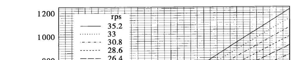
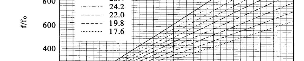
27 Use of similitude For a rigid rotor, the broadband unsteady thrust spectrum is a function of several parameters GT GT D, n,, V, Pv,, c, f In non-dimensional parameters G T Assumptions F J,, Re, M, f / n nd Advance ratio is constant Cavitation index is high enough so cavitation does not occur Reynolds number: small influence Mach number: small Jonson M., Young, S., Decomposition of Structural and Hydrodynamic Contributions for Unsteady Rotor Thrust, Proceedings of the ASME Noise Control and Acoustics Division, NCA-Vol. 21, p. 77,
28 Propeller and thrust dynamometer 28
29 Calibration without propeller 29

30 Unsteady Thrust due to Grid Turbulence 30
31 Non-dimensional Thrust Spectrum Poor collapse at high frequencies. 31
32 Decomposition Method Consider an elastic rotor G T H f / n S f / f nd where H is the hydrodynamic excitation and S is the structural response These terms are solved iteratively or through least squares. A degree of arbitrariness is introduced requiring the engineer to assume a level for S 0 such as at η 0. G, ij i j nd H is j 0 32
33 Transformed Variable Space 33
34 Results 34
35 General Procedure 35
36 Conclusions Dynamometry uses, complexity, and design approach was discussed. Example dynamometry using strain and piezoelectric force gages was provided. Using similitude, additional physics can be gained from the dynamometry. 36
37 References Dan MihaiŞtefănescu, Handbook of Force Transducers: Principles and Components, Springer, 2011 Erdem Canbay, Ugar Ersoy and Tagrul Tankut, A three component force transducer for reinforced concrete structural testing, Engineering Structures, 26 pp , 2004 Jonson, M, Lysak, P, and Willits, S., Smart Materials for Turbomachinery Quieting, Proceeding of the SPIE, Vol. 3991, p. 86, Jonson M., Young, S., Decomposition of Structural and Hydrodynamic Contributions for Unsteady Rotor Thrust, Proceedings of the ASME Noise Control and Acoustics Division, NCA-Vol. 21, p. 77,
38 Acknowledgements Jon Bechtel, Tyler Dare, and Steve Hambric 38
Lecture 19. Measurement of Solid-Mechanical Quantities (Chapter 8) Measuring Strain Measuring Displacement Measuring Linear Velocity
 Measuring Strain Measuring Displacement Measuring Linear Velocity") MECH 373 Instrumentation and Measurements Lecture 19 Measurement of Solid-Mechanical Quantities (Chapter 8) Measuring Strain Measuring Displacement Measuring Linear Velocity Measuring Accepleration and
MECH 373 Instrumentation and Measurements Lecture 19 Measurement of Solid-Mechanical Quantities (Chapter 8) Measuring Strain Measuring Displacement Measuring Linear Velocity Measuring Accepleration and
APPLICATIONS OF VIBRATION TRANSDUCERS
 APPLICATIONS OF VIBRATION TRANSDUCERS 1) Measurements on Structures or Machinery Casings: Accelerometers and Velocity Sensors Used in gas turbines, axial compressors, small and mid-size pumps. These sensors
Mechatronics II Laboratory EXPERIMENT #1: FORCE AND TORQUE SENSORS DC Motor Characteristics Dynamometer, Part I
 Mechatronics II Laboratory EXPEIMENT #1: FOCE AND TOQUE SENSOS DC Motor Characteristics Dynamometer, Part I Force Sensors Force and torque are not measured directly. Typically, the deformation or strain
Mechatronics II Laboratory EXPERIMENT #1 MOTOR CHARACTERISTICS FORCE/TORQUE SENSORS AND DYNAMOMETER PART 1
 Mechatronics II Laboratory EXPEIMENT #1 MOTO CHAACTEISTICS FOCE/TOQUE SENSOS AND DYNAMOMETE PAT 1 Force Sensors Force and torque are not measured directly. Typically, the deformation or strain of some
Strain and Force San José State University A. Mysore Spring 2009
 Strain and Force Strain Gage Measures strain as a change in length L, observed by change in resistance R, for a given resistivity ρ and cross-sectional area A. For elastic materials that follow Hooke s
Solved Problems. Electric Circuits & Components. 1-1 Write the KVL equation for the circuit shown.
 Solved Problems Electric Circuits & Components 1-1 Write the KVL equation for the circuit shown. 1-2 Write the KCL equation for the principal node shown. 1-2A In the DC circuit given in Fig. 1, find (i)
Force and Displacement Measurement
 Force and Displacement Measurement Prof. R.G. Longoria Updated Fall 20 Simple ways to measure a force http://scienceblogs.com/dotphysics/200/02/diy_force_probe.php Example: Key Force/Deflection measure
Chapter 12. Static Equilibrium and Elasticity
 Chapter 12 Static Equilibrium and Elasticity Static Equilibrium Equilibrium implies that the object moves with both constant velocity and constant angular velocity relative to an observer in an inertial
I. MEASUREMENT OF TEMPERATURE
 I. MEASUREMENT OF TEMPERATURE Most frequent measurement and control Direct contact: thermometer, Indirect contact: pyrometer (detect generated heat or sensing optical properties) 1. Definition of temperature
Structural Dynamics Lecture 2. Outline of Lecture 2. Single-Degree-of-Freedom Systems (cont.)
") Outline of Single-Degree-of-Freedom Systems (cont.) Linear Viscous Damped Eigenvibrations. Logarithmic decrement. Response to Harmonic and Periodic Loads. 1 Single-Degreee-of-Freedom Systems (cont.). Linear
Outline of Single-Degree-of-Freedom Systems (cont.) Linear Viscous Damped Eigenvibrations. Logarithmic decrement. Response to Harmonic and Periodic Loads. 1 Single-Degreee-of-Freedom Systems (cont.). Linear
ME411 Engineering Measurement & Instrumentation. Winter 2017 Lecture 9
 ME411 Engineering Measurement & Instrumentation Winter 2017 Lecture 9 1 Introduction If we design a load bearing component, how do we know it will not fail? Simulate/predict behavior from known fundamentals
Lecture 20. Measuring Pressure and Temperature (Chapter 9) Measuring Pressure Measuring Temperature MECH 373. Instrumentation and Measurements
 Measuring Pressure Measuring Temperature MECH 373. Instrumentation and Measurements") MECH 373 Instrumentation and Measurements Lecture 20 Measuring Pressure and Temperature (Chapter 9) Measuring Pressure Measuring Temperature 1 Measuring Acceleration and Vibration Accelerometers using
MECH 373 Instrumentation and Measurements Lecture 20 Measuring Pressure and Temperature (Chapter 9) Measuring Pressure Measuring Temperature 1 Measuring Acceleration and Vibration Accelerometers using
Strain Measurements. Isaac Choutapalli
 Note that for axial elongation (Eaxiai > 0), Erransverse (from Equation C.6), and therefore Strain Measurements Isaac Choutapalli Department of Mechanical Engineering The University of Texas - Pan American
(Refer Slide Time 1:33)
") Mechanical Measurements and Metrology Prof. S. P. Venkateshan Department of Mechanical Engineering Indian Institute of Technology, Madras Module - 4 Lecture - 45 Measurement of Force This will be lecture
Mechanical Measurements and Metrology Prof. S. P. Venkateshan Department of Mechanical Engineering Indian Institute of Technology, Madras Module - 4 Lecture - 45 Measurement of Force This will be lecture
Nonlinear Dynamic Analysis of a Hydrodynamic Journal Bearing Considering the Effect of a Rotating or Stationary Herringbone Groove
 G. H. Jang e-mail: ghjang@hanyang.ac.kr J. W. Yoon PREM, Department of Mechanical Engineering, Hanyang University, Seoul, 133-791, Korea Nonlinear Dynamic Analysis of a Hydrodynamic Journal Bearing Considering
 Set No. 1 1. (a) Differentiate among Desired, Modifying and Interfering inputs. (b) How do you eliminate the effects of interfering and modifying inputs? Explain 2. (a) Define the term Transducer and explain
Theory and Practice of Rotor Dynamics Prof. Rajiv Tiwari Department of Mechanical Engineering Indian Institute of Technology Guwahati
 Theory and Practice of Rotor Dynamics Prof. Rajiv Tiwari Department of Mechanical Engineering Indian Institute of Technology Guwahati Module - 7 Instability in rotor systems Lecture - 4 Steam Whirl and
6. Strain Gages and Strain Measurement
 6. Strain Gages and Strain Measurement 6.1 Strain gages: (Silva p.273) Strain gage measures strain and the measurements can be directly related to stress and force. Hence, strain gages can be utilized
Dynamics of assembled structures of rotor systems of aviation gas turbine engines of type two-rotor
 Dynamics of assembled structures of rotor systems of aviation gas turbine engines of type two-rotor Anatoly А. Pykhalov 1, Mikhail А. Dudaev 2, Mikhail Ye. Kolotnikov 3, Paul V. Makarov 4 1 Irkutsk State
MET 487 Instrumentation and Automatic Controls. Lecture 13 Sensors
 MET 87 nstrumentation and utomatic Controls Lecture Sensors July 6-9, 00 Stress and Strain Measurement Safe Load Level monitoring Force (indirect measurement by measuring strain of a flexural element Pressure
STRAIN GAUGES YEDITEPE UNIVERSITY DEPARTMENT OF MECHANICAL ENGINEERING
 STRAIN GAUGES YEDITEPE UNIVERSITY DEPARTMENT OF MECHANICAL ENGINEERING 1 YEDITEPE UNIVERSITY ENGINEERING FACULTY MECHANICAL ENGINEERING LABORATORY 1. Objective: Strain Gauges Know how the change in resistance
MET 301 EXPERIMENT # 2 APPLICATION OF BONDED STRAIN GAGES
 MET 301 EPERIMENT # 2 APPLICATION OF BONDED STRAIN GAGES 1. Objective To understand the working principle of bonded strain gauge and to study the stress and strain in a hollow cylindrical shaft under bending,
What is a Strain Gauge? Strain Gauge. Schematic View Of Strain Gauge
 ( ) : 1391-92 92 What is Strain? Strain is the amount of deformation of a body due to an applied force. More specifically, strain (ε) is defined as the fractional change in length. Strain can be positive
Module 2 Stresses in machine elements. Version 2 ME, IIT Kharagpur
 Module Stresses in machine elements Lesson Compound stresses in machine parts Instructional Objectives t the end of this lesson, the student should be able to understand Elements of force system at a beam
TrueStructures TM Strain Analysis System
 TrueStructures TM Strain Analysis System Operator's Manual and Sample Lab Procedures TrueStructures TM Strain Analysis System shown with I-Beam, Torsion Tube and Airfoil Test Sections. Copyright March
Introduction to Strain Gage (SG) Technology
 Technology") IDMIL - Input Devices and Music Interaction Laboratory McGill University Introduction to Strain Gage (SG) Technology Carolina Brum Medeiros March 14, 2011 About this talk objective: present the essential
IDMIL - Input Devices and Music Interaction Laboratory McGill University Introduction to Strain Gage (SG) Technology Carolina Brum Medeiros March 14, 2011 About this talk objective: present the essential
Dynamic Modeling of Fluid Power Transmissions for Wind Turbines
 Dynamic Modeling of Fluid Power Transmissions for Wind Turbines EWEA OFFSHORE 211 N.F.B. Diepeveen, A. Jarquin Laguna n.f.b.diepeveen@tudelft.nl, a.jarquinlaguna@tudelft.nl Offshore Wind Group, TU Delft,
Shafts: Torsion of Circular Shafts Reading: Crandall, Dahl and Lardner 6.2, 6.3
 M9 Shafts: Torsion of Circular Shafts Reading: Crandall, Dahl and Lardner 6., 6.3 A shaft is a structural member which is long and slender and subject to a torque (moment) acting about its long axis. We
Investigation of Coupled Lateral and Torsional Vibrations of a Cracked Rotor Under Radial Load
 NOMENCLATURE Investigation of Coupled Lateral and Torsional Vibrations of a Cracked Rotor Under Radial Load Xi Wu, Assistant Professor Jim Meagher, Professor Clinton Judd, Graduate Student Department of
Multi-Capacity Load Cell Concept
 Sensors & Transducers 4 by IFSA Publishing, S. L. http://www.sensorsportal.com Multi-Capacity Load Cell Concept Seif. M. OSMAN, Ebtisam H. HASAN, H. M. EL-HAKEEM, R. M. RASHAD, F. KOUTA National Institute
Journey Through a Project: Shake-table Test of a Reinforced Masonry Structure
 Journey Through a Project: Shake-table Test of a Reinforced Masonry Structure P. Benson Shing and Andreas Koutras Department of Structural Engineering University of California, San Diego NHERI @ UCSD Workshop,
PROPELLER INDUCED STRUCTURAL VIBRATION THROUGH THE THRUST BEARING
 PROPELLER INDUCED TRUCTURAL VIBRATION THROUGH THE THRUT BEARING Jie Pan, Nabil Farag, Terry Lin and Ross Juniper* DEPARTMENT OF MECHANICAL AND MATERIAL ENGINEERING THE UNIVERITY OF WETERN AUTRALIA 35 TIRLING
Excerpt from the Proceedings of the COMSOL Conference 2010 Boston
 Excerpt from the Proceedings of the COMSOL Conference 21 Boston Uncertainty Analysis, Verification and Validation of a Stress Concentration in a Cantilever Beam S. Kargar *, D.M. Bardot. University of
ENSC387: Introduction to Electromechanical Sensors and Actuators LAB 3: USING STRAIN GAUGES TO FIND POISSON S RATIO AND YOUNG S MODULUS
 ENSC387: Introduction to Electromechanical Sensors and Actuators LAB 3: USING STRAIN GAUGES TO FIND POISSON S RATIO AND YOUNG S MODULUS 1 Introduction... 3 2 Objective... 3 3 Supplies... 3 4 Theory...
University of Jordan Faculty of Engineering & Technology Electric Power Engineering Department
 University of Jordan Faculty of Engineering & Technology Electric Power Engineering Department EE471: Electrical Machines-II Tutorial # 2: 3-ph Induction Motor/Generator Question #1 A 100 hp, 60-Hz, three-phase
Introduction to Turbomachinery
 1. Coordinate System Introduction to Turbomachinery Since there are stationary and rotating blades in turbomachines, they tend to form a cylindrical form, represented in three directions; 1. Axial 2. Radial
1 Force Sensing. Lecture Notes. 1.1 Load Cell. 1.2 Stress and Strain
 Lecture Notes 1 Force Sensing 1.1 Load Cell A Load Cell is a structure which supports the load and deflects a known amount in response to applied forces and torques. The deflections are measured to characterize
Wheatstone Bridge Nonlinearity
 Index: Nonlinearity Wheatstone Bridge Nonlinearity Introduction General Considerations The "Unbalanced" Circuit The Unbalanced Circuit Table of Contents Output & Nonlinearity with Various Bridge/Strain
ECEN 420 LINEAR CONTROL SYSTEMS. Lecture 6 Mathematical Representation of Physical Systems II 1/67
 1/67 ECEN 420 LINEAR CONTROL SYSTEMS Lecture 6 Mathematical Representation of Physical Systems II State Variable Models for Dynamic Systems u 1 u 2 u ṙ. Internal Variables x 1, x 2 x n y 1 y 2. y m Figure
Chapter 7 Vibration Measurement and Applications
 Chapter 7 Vibration Measurement and Applications Dr. Tan Wei Hong School of Mechatronic Engineering Universiti Malaysia Perlis (UniMAP) Pauh Putra Campus ENT 346 Vibration Mechanics Chapter Outline 7.1
AC : ENGINEERING SQUEEZEOMETER AND HUGGOME- TER
 AC 202-50: ENGNEERNG SQUEEZEOMETER AND HUGGOME- TER Dr. James Aflaki, Christian Brothers University James Aflaki received his Ph.D. in mechanical engineering from the University of Maryland, College Park.
Bending Load & Calibration Module
 Bending Load & Calibration Module Objectives After completing this module, students shall be able to: 1) Conduct laboratory work to validate beam bending stress equations. 2) Develop an understanding of
HELICAL BUCKLING OF DRILL-STRINGS
 HELICAL BUCKLING OF DRILL-STRINGS Marcin Kapitaniak 1,, Vahid Vaziri 1,, and Marian Wiercigroch 1 1 Centre for Applied Dynamics Research, School of Engineering, University of Aberdeen, Aberdeen, AB24 3UE,
Model of a DC Generator Driving a DC Motor (which propels a car)
") Model of a DC Generator Driving a DC Motor (which propels a car) John Hung 5 July 2011 The dc is connected to the dc as illustrated in Fig. 1. Both machines are of permanent magnet type, so their respective
Model of a DC Generator Driving a DC Motor (which propels a car) John Hung 5 July 2011 The dc is connected to the dc as illustrated in Fig. 1. Both machines are of permanent magnet type, so their respective
Module 2 Mechanics of Machining. Version 2 ME IIT, Kharagpur
 Module 2 Mechanics of Machining Lesson 10 Dynamometers for measuring cutting forces Instructional objectives At the end of this lesson, the students would be able to (i) (ii) (iii) (iv) show the general
Fluid Mechanics. du dy
 FLUID MECHANICS Technical English - I 1 th week Fluid Mechanics FLUID STATICS FLUID DYNAMICS Fluid Statics or Hydrostatics is the study of fluids at rest. The main equation required for this is Newton's
Finite Element Analysis Prof. Dr. B. N. Rao Department of Civil Engineering Indian Institute of Technology, Madras. Module - 01 Lecture - 13
 Finite Element Analysis Prof. Dr. B. N. Rao Department of Civil Engineering Indian Institute of Technology, Madras (Refer Slide Time: 00:25) Module - 01 Lecture - 13 In the last class, we have seen how
SSNEMS Internal Report
 E.3. Nanotube Reinforced Piezoelectric Polymeric Composites Subjected to Electro-Thermo- Mechanical Loadings Understanding the stress transfer between nanotube reinforcements and surrounding matrix is
ENGR 4011 Resistance & Propulsion of Ships Assignment 4: 2017
 Question 1a. Values of forward speed, propeller thrust and torque measured during a propeller open water performance test are presented in the table below. The model propeller was 0.21 meters in diameter
The application of Eulerian laser Doppler vibrometry to the on-line condition monitoring of axial-flow turbomachinery blades
 UNIVERSITY OF PRETORIA The application of Eulerian laser Doppler vibrometry to the on-line condition monitoring of axial-flow turbomachinery blades by Abrie Oberholster Supervisor: Professor Stephan Heyns
Members Subjected to Combined Loads
 Members Subjected to Combined Loads Combined Bending & Twisting : In some applications the shaft are simultaneously subjected to bending moment M and Torque T.The Bending moment comes on the shaft due
Experimental Investigation of Transient Hydrodynamic Forces of a Single-Blade Centrifugal Pump
 Proceedings of the 4th WSEAS International Conference on luid Mechanics and Aerodynamics, Elounda, Greece, August 1-, 006 (pp1-6) Experimental Investigation of Transient Hydrodynamic orces of a Single-Blade
High Temperature Strain Measurements Using Fiber Optic Sensors
 High Temperature Strain Measurements Using Fiber Optic Sensors Paul J. Gloeckner, Ph.D. Cummins, Inc. 1900 McKinley Ave. Columbus, IN 47201 ABSTRACT Strain gage measurements at elevated temperatures (>
MENG 302L Lab 6: Stress Concentration
 Introduction 1 : The purpose of this experiment is to demonstrate the existence of stress and strain concentration in the vicinity of a geometric discontinuity in a cantilever beam, and to obtain an approximate
Experiment Two (2) Torsional testing of Circular Shafts
 Torsional testing of Circular Shafts") Experiment Two (2) Torsional testing of Circular Shafts Introduction: Torsion occurs when any shaft is subjected to a torque. This is true whether the shaft is rotating (such as drive shafts on engines,
Experiment Two (2) Torsional testing of Circular Shafts Introduction: Torsion occurs when any shaft is subjected to a torque. This is true whether the shaft is rotating (such as drive shafts on engines,
Application of Nonlinear Dynamics Tools for Diagnosis of Cracked Rotor Vibration Signatures
 Application of Nonlinear Dynamics Tools for Diagnosis of Cracked Rotor Vibration Signatures Jery T. Sawicki *, Xi Wu *, Andrew L. Gyekenyesi **, George Y. Baaklini * Cleveland State University, Dept. of
SAMCEF For ROTORS. Chapter 1 : Physical Aspects of rotor dynamics. This document is the property of SAMTECH S.A. MEF A, Page 1
 SAMCEF For ROTORS Chapter 1 : Physical Aspects of rotor dynamics This document is the property of SAMTECH S.A. MEF 101-01-A, Page 1 Table of Contents rotor dynamics Introduction Rotating parts Gyroscopic
Measurement Techniques for Engineers. Motion and Vibration Measurement
 Measurement Techniques for Engineers Motion and Vibration Measurement Introduction Quantities that may need to be measured are velocity, acceleration and vibration amplitude Quantities useful in predicting
Attempt ALL QUESTIONS IN SECTION A, ONE QUESTION FROM SECTION B and ONE QUESTION FROM SECTION C Linear graph paper will be provided.
 UNIVERSITY OF EAST ANGLIA School of Mathematics Main Series UG Examination 2015-2016 ENERGY ENGINEERING PRINCIPLES ENG-5001Y Time allowed: 3 Hours Attempt ALL QUESTIONS IN SECTION A, ONE QUESTION FROM
Potsdam Propeller Test Case (PPTC) Test Case Description
 Test Case Description") Second International Symposium on Marine Propulsors smp 11, Hamburg, Germany, June 2011 Workshop: Propeller performance Potsdam Propeller Test Case (PPTC) Test Case Description Ulf Barkmann 1, Hans-Jürgen
Second International Symposium on Marine Propulsors smp 11, Hamburg, Germany, June 2011 Workshop: Propeller performance Potsdam Propeller Test Case (PPTC) Test Case Description Ulf Barkmann 1, Hans-Jürgen
DREDGING DYNAMICS AND VIBRATION MEASURES
 DREDGING DYNAMICS AND VIBRATION MEASURES C R Barik, K Vijayan, Department of Ocean Engineering and Naval Architecture, IIT Kharagpur, India ABSTRACT The demands for dredging have found a profound increase
Contents. 2 Basic Components Aerofoils Force Generation Performance Parameters xvii
 Contents 1 Working Principles... 1 1.1 Definition of a Turbomachine... 1 1.2 Examples of Axial Turbomachines... 2 1.2.1 Axial Hydraulic Turbine... 2 1.2.2 Axial Pump... 4 1.3 Mean Line Analysis... 5 1.4
Lesson 17: Synchronous Machines
 Lesson 17: Synchronous Machines ET 332b Ac Motors, Generators and Power Systems Lesson 17_et332b.pptx 1 Learning Objectives After this presentation you will be able to: Explain how synchronous machines
STRAIN INSTRUMENTATION SYSTEM MODELING AND PERFROMANCE ANALYSIS
 International Journal of Advance Studies in Engineering and Scientific Inventions Volume 3 Number 1, JULY 2015. ISSN (Print): 1741-8763 ISSN (Online):1741-8771 STRAIN INSTRUMENTATION SYSTEM MODELING AND
SYSTEM IDENTIFICATION & DAMAGE ASSESSMENT OF STRUCTURES USING OPTICAL TRACKER ARRAY DATA
 SYSTEM IDENTIFICATION & DAMAGE ASSESSMENT OF STRUCTURES USING OPTICAL TRACKER ARRAY DATA Chin-Hsiung Loh 1,* and Chuan-Kai Chan 1 1 Department of Civil Engineering, National Taiwan University Taipei 10617,
EFFECT OF HYDRODYNAMIC THRUST BEARINGS ON ROTORDYNAMICS
 The 12th International Symposium on Transport Phenomena and Dynamics of Rotating Machinery Honolulu, Hawaii, February 17-22, 2008 ISROMAC12-2008-20076 EFFECT OF HYDRODYNAMIC THRUST BEARINGS ON ROTORDYNAMICS
Pushover Seismic Analysis of Bridge Structures
 Pushover Seismic Analysis of Bridge Structures Bernardo Frère Departamento de Engenharia Civil, Arquitectura e Georrecursos, Instituto Superior Técnico, Technical University of Lisbon, Portugal October
Propeller Loads of Large Commercial Vessels at Crash Stop
 Second International Symposium on Marine Propulsors smp 11, Hamburg, Germany, June 2011 Propeller Loads of Large Commercial Vessels at Crash Stop J.W. Hur, H. Lee, B.J. Chang 1 1 Hyundai Heavy Industries,
Laboratory 7 Measurement on Strain & Force. Department of Mechanical and Aerospace Engineering University of California, San Diego MAE170
 Laboratory 7 Measurement on Strain & Force Department of Mechanical and Aerospace Engineering University of California, San Diego MAE170 Megan Ong Diana Wu Wong B01 Tuesday 11am May 17 th, 2015 Abstract:
VIBRATION ANALYSIS IN SHIP STRUCTURES BY FINITE ELEMENT METHOD
 Proceedings of COBEM 2007 Copyright 2007 by ABCM 19th International Congress of Mechanical Engineering November 5-9, 2007, Brasília, DF VIBRATION ANALYSIS IN SHIP STRUCTURES BY FINITE ELEMENT METHOD Luiz
Basic Fluid Mechanics
 Basic Fluid Mechanics Chapter 5: Application of Bernoulli Equation 4/16/2018 C5: Application of Bernoulli Equation 1 5.1 Introduction In this chapter we will show that the equation of motion of a particle
The Forcing of Wind Turbine Rotors by True Weather Events as a Function of Atmospheric Stability State*
 NAWEA 2015 Symposium 11 June 2015 Virginia Tech, Blacksburg, VA The Forcing of Wind Turbine Rotors by True Weather Events as a Function of Atmospheric Stability State* Balaji Jayaraman 1 and James G. Brasseur
Part 2. Sensor and Transducer Instrument Selection Criteria (3 Hour)
") Part 2 Sensor and Transducer Instrument Selection Criteria (3 Hour) At the end of this chapter, you should be able to: Describe the definition of sensor and transducer Determine the specification of control
Part 2 Sensor and Transducer Instrument Selection Criteria (3 Hour) At the end of this chapter, you should be able to: Describe the definition of sensor and transducer Determine the specification of control
Data Logger V2. Instruction Manual
 Data Logger V2 Instruction Manual Joe Holdsworth 7-29-2018 Contents Revision History... 2 Specifications... 3 Power Limits... 3 Data Rates... 3 Other Specifications... 3 Pin Outs... 4 AS218-35SN... 4 AS210-35SN...
Hot Strain Gage Processing using ncode Glyphworks. Dave Woerner, Senior Principal Test & Durability Engineer, Faurecia
 Hot Strain Gage Processing using ncode Glyphworks Dave Woerner, Senior Principal Test & Durability Engineer, Faurecia Acknowledgements Mr. John Menefee, FECT For Python Script Programming 2 Motivations
inter.noise 2000 The 29th International Congress and Exhibition on Noise Control Engineering August 2000, Nice, FRANCE
 1 inter.noise 2000 The 29th International Congress and Exhibition on Noise Control Engineering 27-30 August 2000, Nice, FRANCE I-INCE Classification: 1.0 PREDICTION OF LOW FREQUENCY SOUND GENERATION FROM
UNIT-I (FORCE ANALYSIS)
") DHANALAKSHMI SRINIVASAN INSTITUTE OF RESEACH AND TECHNOLOGY DEPARTMENT OF MECHANICAL ENGINEERING QUESTION BANK ME2302 DYNAMICS OF MACHINERY III YEAR/ V SEMESTER UNIT-I (FORCE ANALYSIS) PART-A (2 marks)
DHANALAKSHMI SRINIVASAN INSTITUTE OF RESEACH AND TECHNOLOGY DEPARTMENT OF MECHANICAL ENGINEERING QUESTION BANK ME2302 DYNAMICS OF MACHINERY III YEAR/ V SEMESTER UNIT-I (FORCE ANALYSIS) PART-A (2 marks)
Penn State Center for Acoustics and Vibration (CAV)
") Penn State Center for Acoustics and Vibration (CAV) Structural Vibration and Acoustics Group Presented as part of the 2015 CAV Spring workshop Stephen Hambric, Group Leader May 2015 Robert Campbell James
Penn State Center for Acoustics and Vibration (CAV) Structural Vibration and Acoustics Group Presented as part of the 2015 CAV Spring workshop Stephen Hambric, Group Leader May 2015 Robert Campbell James
PIEZOELECTRIC TECHNOLOGY PRIMER
 PIEZOELECTRIC TECHNOLOGY PRIMER James R. Phillips Sr. Member of Technical Staff CTS Wireless Components 4800 Alameda Blvd. N.E. Albuquerque, New Mexico 87113 Piezoelectricity The piezoelectric effect is
(Refer Slide Time: 1: 19)
") Mechanical Measurements and Metrology Prof. S. P. Venkateshan Department of Mechanical Engineering Indian Institute of Technology, Madras Module - 4 Lecture - 46 Force Measurement So this will be lecture
Mechanical Measurements and Metrology Prof. S. P. Venkateshan Department of Mechanical Engineering Indian Institute of Technology, Madras Module - 4 Lecture - 46 Force Measurement So this will be lecture
DESIGN AND CONSTRUCTION OF A WATER TUNNEL. Stephen C. Ko
 i DESGN AND CONSTRUCTON OF A WATER TUNNEL By Stephen C. Ko This work has been carried out as a part of a grant from the National Science Foundation for the development of fluid mechanics laboratory equipments
1. Distinguish the important characteristics of instrument that are totally electrical and totally electronic in nature. [16]
![1. Distinguish the important characteristics of instrument that are totally electrical and totally electronic in nature. [16]](/thumbs/96/127822274.jpg "1. Distinguish the important characteristics of instrument that are totally electrical and totally electronic in nature. [16]") Code No: RR320204 Set No. 1 1. Distinguish the important characteristics of instrument that are totally electrical and totally electronic in nature. [16] 2. Distinguish between deterministic signals and
Code No: RR320204 Set No. 1 1. Distinguish the important characteristics of instrument that are totally electrical and totally electronic in nature. [16] 2. Distinguish between deterministic signals and
7.Piezoelectric, Accelerometer and Laser Sensors
 7.Piezoelectric, Accelerometer and Laser Sensors 7.1 Piezoelectric sensors: (Silva p.253) Piezoelectric materials such as lead-zirconate-titanate (PZT) can generate electrical charge and potential difference
Analysis of Crashback Forces Compared with Experimental Results
 First International Symposium on Marine Propulsors SMP 09, Trondheim, Norway, une 2009 Analysis of Crashback Forces Compared with Experimental Results Scott Black and Susan Swithenbank Naval Surface Warfare
Support Reactions: a + M C = 0; 800(10) F DE(4) F DE(2) = 0. F DE = 2000 lb. + c F y = 0; (2000) - C y = 0 C y = 400 lb
 F DE(4) F DE(2) = 0. F DE = 2000 lb. + c F y = 0; (2000) - C y = 0 C y = 400 lb") 06 Solutions 46060_Part1 5/27/10 3:51 P Page 334 6 11. The overhanging beam has been fabricated with a projected arm D on it. Draw the shear and moment diagrams for the beam C if it supports a load of
06 Solutions 46060_Part1 5/27/10 3:51 P Page 334 6 11. The overhanging beam has been fabricated with a projected arm D on it. Draw the shear and moment diagrams for the beam C if it supports a load of
MECHANICS LAB AM 317 EXP 3 BENDING STRESS IN A BEAM
 MECHANICS LAB AM 37 EXP 3 BENDING STRESS IN A BEAM I. OBJECTIVES I. To compare the experimentally determined stresses in a beam with those predicted from the simple beam theory (a.k.a. Euler-Bernoull beam
Chapter 3. Inertia. Force. Free Body Diagram. Net Force. Mass. quantity of matter composing a body represented by m. units are kg
 Chapter 3 Mass quantity of matter composing a body represented by m Kinetic Concepts for Analyzing Human Motion units are kg Inertia tendency to resist change in state of motion proportional to mass has
ON NUMERICAL ANALYSIS AND EXPERIMENT VERIFICATION OF CHARACTERISTIC FREQUENCY OF ANGULAR CONTACT BALL-BEARING IN HIGH SPEED SPINDLE SYSTEM
 ON NUMERICAL ANALYSIS AND EXPERIMENT VERIFICATION OF CHARACTERISTIC FREQUENCY OF ANGULAR CONTACT BALL-BEARING IN HIGH SPEED SPINDLE SYSTEM Tian-Yau Wu and Chun-Che Sun Department of Mechanical Engineering,
CE 320 Structures Laboratory 1 Flexure Fall 2006
 CE 320 Structures Laboratory 1 Flexure Fall 2006 General Note: All structures labs are to be conducted by teams of no more than four students. Teams are expected to meet to decide on an experimental design
Aeroacoustic and Aerodynamics of Swirling Flows*
 Aeroacoustic and Aerodynamics of Swirling Flows* Hafiz M. Atassi University of Notre Dame * supported by ONR grant and OAIAC OVERVIEW OF PRESENTATION Disturbances in Swirling Flows Normal Mode Analysis
CHAPTER -6- BENDING Part -1-
 Ishik University / Sulaimani Civil Engineering Department Mechanics of Materials CE 211 CHAPTER -6- BENDING Part -1-1 CHAPTER -6- Bending Outlines of this chapter: 6.1. Chapter Objectives 6.2. Shear and
3 Hours/100 Marks Seat No.
 *17304* 17304 14115 3 Hours/100 Marks Seat No. Instructions : (1) All questions are compulsory. (2) Illustrate your answers with neat sketches wherever necessary. (3) Figures to the right indicate full
Non-Synchronous Vibrations of Turbomachinery Airfoils
 Non-Synchronous Vibrations of Turbomachinery Airfoils 600 500 NSV Frequency,!, hz 400 300 200 F.R. Flutter 100 SFV 0 0 1000 2000 3000 4000 5000 6000 7000 8000 9000 10000 Rotor Speed,!, RPM Kenneth C. Hall,
FE Exam Fluids Review October 23, Important Concepts
 FE Exam Fluids Review October 3, 013 mportant Concepts Density, specific volume, specific weight, specific gravity (Water 1000 kg/m^3, Air 1. kg/m^3) Meaning & Symbols? Stress, Pressure, Viscosity; Meaning
UNIT 4 FLYWHEEL 4.1 INTRODUCTION 4.2 DYNAMICALLY EQUIVALENT SYSTEM. Structure. Objectives. 4.1 Introduction
 UNIT 4 FLYWHEEL Structure 4.1 Introduction Objectives 4. Dynamically Equivalent System 4.3 Turning Moment Diagram 4.3.1 Turning Moment Diagram of a Single Cylinder 4-storke IC Engine 4.3. Turning Moment
6. Bending CHAPTER OBJECTIVES
 CHAPTER OBJECTIVES Determine stress in members caused by bending Discuss how to establish shear and moment diagrams for a beam or shaft Determine largest shear and moment in a member, and specify where
Implementation of a Thermo- Hydrodynamic Model to Predict Morton Effect
 Implementation of a Thermo- Hydrodynamic Model to Predict Morton Effect Antonini *, Fausti and Mor Polibrixia srl, Via A. Tadini 49, 25125 Brescia. *orresponding author: Via Branze 45, 25123 Brescia, massimo.antonini@polibrixia.it
Mitigation of Diesel Generator Vibrations in Nuclear Applications Antti Kangasperko. FSD3020xxx-x_01-00
 Mitigation of Diesel Generator Vibrations in Nuclear Applications Antti Kangasperko FSD3020xxx-x_01-00 1 Content Introduction Vibration problems in EDGs Sources of excitation 2 Introduction Goal of this
Module I Module I: traditional test instrumentation and acquisition systems. Prof. Ramat, Stefano
 Preparatory Course (task NA 3.6) Basics of experimental testing and theoretical background Module I Module I: traditional test instrumentation and acquisition systems Prof. Ramat, Stefano Transducers A
Vibration Analysis Of Cantilever Shaft With Transverse Cracks
 Vibration Analysis Of Cantilever Shaft With Transverse Cracks R.K Behera, D.R.K. Parhi, S.K. Pradhan, and Seelam Naveen Kumar Dept. of Mech Engg. N.I.T., Rourkela,7698 Dept. of Mech. Engg Dept. of Mech.