Chapter 21. Ac Circuits
|
|
|
- Basil Wiggins
- 6 years ago
- Views:
Transcription
1 Chapter 21 Ac Circuits

2 AC current


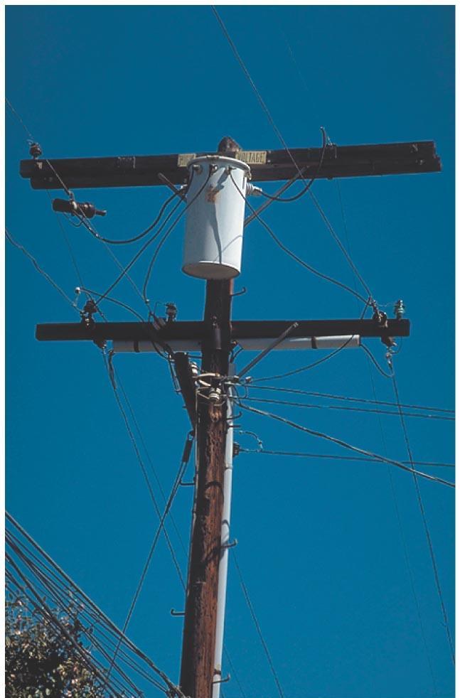
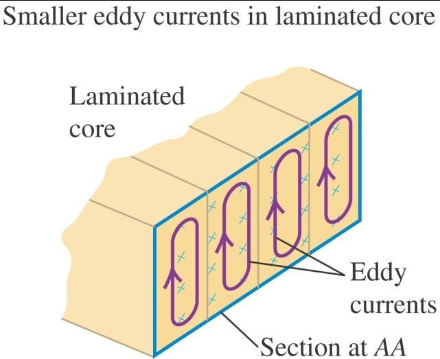
3 Transformer Transforms AC voltage UP or DOWN Historical basis for AC Grid your use George Westinghouse (AC) vs Edison (DC) Losses due to resistance in wire and eddy currents in transformer core Typ eff ~ 95-99%
4 Transformers
5 Transformers II

6 CHAPTER 21: FIGURE 21-3 COLLEGE PHYSICS FREEDMAN RUSKELL KESTEN TAUCK 2014 W. H. FREEMAN AND COMPANY

7 CHAPTER 21: INTRO COLLEGE PHYSICS FREEDMAN RUSKELL KESTEN TAUCK 2014 W. H. FREEMAN AND COMPANY

8 CHAPTER 21: 21-1 COLLEGE PHYSICS FREEDMAN RUSKELL KESTEN TAUCK 2014 W. H. FREEMAN AND COMPANY

9 CHAPTER 21: 21-2 COLLEGE PHYSICS FREEDMAN RUSKELL KESTEN TAUCK 2014 W. H. FREEMAN AND COMPANY

10 CHAPTER 21: FIGURE 21-2 COLLEGE PHYSICS FREEDMAN RUSKELL KESTEN TAUCK 2014 W. H. FREEMAN AND COMPANY

11 CHAPTER 21: 21-3 COLLEGE PHYSICS FREEDMAN RUSKELL KESTEN TAUCK 2014 W. H. FREEMAN AND COMPANY
12 CHAPTER 21: 21-4_2 COLLEGE PHYSICS FREEDMAN RUSKELL KESTEN TAUCK 2014 W. H. FREEMAN AND COMPANY
13 CHAPTER 21: 21-4 COLLEGE PHYSICS FREEDMAN RUSKELL KESTEN TAUCK 2014 W. H. FREEMAN AND COMPANY
14 A full-wave rectifier circuit
15 RC Circuit Exponential Decay An RC circuit is a common circuit used in electronic filters The basic idea is it take time to charge a capacitor thru a resistor Recall that a capacitor C with Voltage V across it has charge Q=CV Current I= dq/dt = C dv/dt In a circuit with a capacitor and resistor in parallel the voltage across the resistor must equal opposite that across the capacitor Hence V c = -V R or Q/C = -IR or Q/C + IR = 0 (note the current I thru the resistor must be responsible for the dq/dt Kirchoff or charge conservation Now take a time derivative dq/dt/c + R di/dt = I/C + R di/dt =0 OR di/dt +I/RC simply first order differential equation Solution is I(t) = I 0 e -t/rc = I 0 e -t/ where = RC is the time constant Voltage across resistor V R (t) = IR = I 0 R e -t/rc = V 0 e -t/rc = - V c (t) voltage across capacitor Note the exponential decay We can also write the eq as R dq/dt + Q/C =0
 = V 0 e")
16 Discharging a capacitor Imagine starting with a capacitor C charged to voltage V 0 Now discharge it starting at t=0 through resistor R V(t) = V 0 e -t/rc
17 Charging a Capacitor Start with a capacitor C that is discharged (0 volts) Now hook up a battery with a resistor R Start the charge at t=0 V(t) = V 0 (1- e -t/rc )
18 RC Circuits Another way Lets analyze this another way In a closed loop the total EMF is zero (must be careful here once we get to induced electric fields from changing magnetic fields) In quasi static case E dl = 0 (voltage sum) over a closed loop Charge across the capacitor Q = CV I = dq/dt = C dv/dt But the same I = -V/R (minus as V across cap is minus across R if we go in a loop) CdV/dt = - V/R or C dv/dt + V/R = 0 or dv/dt + V/RC = 0 Solution is V(t) = V 0 e -t/rc Same solution as before The time required to fall from the initial voltage V 0 to V 0 /e is time = RC

 = -i/( C) is the impedance of a capacitor Note the impedance of a capacitor is complex and proportional to 1/ C - the minus i will indicate a 90")
19 Complex impedances Consider the following series circuit If we put an input Voltage V in across the system We get a differential eq as before but with V in V in + IR + Q/C =0 E dl=0 around the closed loop V in + R dq/dt + Q/C = V in + IR + I dt/c we can write the solution as a complex solution I = I 0 e i t V in + IR + I dt/c We can make this more General letting V in = V 0 e i t This allows a driven osc term freq V 0 e i t + R I 0 e i t + I 0 e i t /(i C) V 0 +R I 0 + I 0 /(i C) - thus we can interpret this as a series of impedances (resistance) Z (general impedance ) where Z R = R is the normal impedance of a resistor and Z c = 1/(i C) = -i/( C) is the impedance of a capacitor Note the impedance of a capacitor is complex and proportional to 1/ C - the minus i will indicate a 90 degree phase shift
20 Q26.9 A battery, a capacitor, and a resistor are connected in series. Which of the following affect(s) the maximum charge stored on the capacitor? A. the emf e of the battery B. the capacitance C of the capacitor C. the resistance R of the resistor D. both e and C E. all three of e, C, and R
21 A26.9 A battery, a capacitor, and a resistor are connected in series. Which of the following affect(s) the maximum charge stored on the capacitor? A. the emf e of the battery B. the capacitance C of the capacitor C. the resistance R of the resistor D. both e and C E. all three of e, C, and R
22 Q26.10 A battery, a capacitor, and a resistor are connected in series. Which of the following affect(s) the rate at which the capacitor charges? A. the emf e of the battery B. the capacitance C of the capacitor C. the resistance R of the resistor D. both C and R E. all three of e, C, and R
23 A26.10 A battery, a capacitor, and a resistor are connected in series. Which of the following affect(s) the rate at which the capacitor charges? A. the emf e of the battery B. the capacitance C of the capacitor C. the resistance R of the resistor D. both C and R E. all three of e, C, and R

24 Current in the device I m using right now A desktop PC draws current from a plug to the wall, but what are the details?

25 CHAPTER 21: 21-5 COLLEGE PHYSICS FREEDMAN RUSKELL KESTEN TAUCK 2014 W. H. FREEMAN AND COMPANY

26 CHAPTER 21: FIGURE 21-4 COLLEGE PHYSICS FREEDMAN RUSKELL KESTEN TAUCK 2014 W. H. FREEMAN AND COMPANY

27 CHAPTER 21: 21-6 COLLEGE PHYSICS FREEDMAN RUSKELL KESTEN TAUCK 2014 W. H. FREEMAN AND COMPANY

28 CHAPTER 21: 21-8 COLLEGE PHYSICS FREEDMAN RUSKELL KESTEN TAUCK 2014 W. H. FREEMAN AND COMPANY

29 CHAPTER 21: 21-11_2 COLLEGE PHYSICS FREEDMAN RUSKELL KESTEN TAUCK 2014 W. H. FREEMAN AND COMPANY

30 CHAPTER 21: FIGURE 21-8_2 COLLEGE PHYSICS FREEDMAN RUSKELL KESTEN TAUCK 2014 W. H. FREEMAN AND COMPANY

31 CHAPTER 21: COLLEGE PHYSICS FREEDMAN RUSKELL KESTEN TAUCK 2014 W. H. FREEMAN AND COMPANY

32 CHAPTER 21: TABLE 21-1 COLLEGE PHYSICS FREEDMAN RUSKELL KESTEN TAUCK 2014 W. H. FREEMAN AND COMPANY
33 Resistors in an AC circuit Ohm s Law applied in oscillatory fashion.
34 Inductors in an AC circuit Replace the resistor in the previous slide with an inductor.
35 Because this is a series circuit, the current is the same through the capacitor as through the resistor just considered. Capacitance in an AC circuit
36 Comparing AC circuit elements Summary of circuit elements. Frequency dependence of reactance
 connect in parallel through a crossover.")
37 The loudspeaker, a useful application The woofer (low tones) and the tweeter (high tones) connect in parallel through a crossover.

38 The L-R-C circuit
39 An L-R-C circuit II
40 Power in an inductor Consider current, voltage, and power as functions of time.
41 Circuit behavior at resonance Look at the maximum I when the impedance is a minimum.
42 Tuning a radio LRC circuit tuned to station AM/ FM radio
Chapter 26 DC Circuits
 Chapter 26 DC Circuits Young and Freedman Univ Physics 12 th Ed. Chapters 26-36 this quarter www.deepspace.ucsb.edu See Classes/ Physics 4 S 2010 Check frequently for updates to HW and tests prof@deepspace.ucsb.edu
Chapter 19 Lecture Notes
 Chapter 19 Lecture Notes Physics 2424 - Strauss Formulas: R S = R 1 + R 2 +... C P = C 1 + C 2 +... 1/R P = 1/R 1 + 1/R 2 +... 1/C S = 1/C 1 + 1/C 2 +... q = q 0 [1-e -t/(rc) ] q = q 0 e -t/(rc τ = RC
Assessment Schedule 2015 Physics: Demonstrate understanding of electrical systems (91526)
") NCEA Level 3 Physics (91526) 2015 page 1 of 6 Assessment Schedule 2015 Physics: Demonstrate understanding of electrical systems (91526) Evidence Q Evidence Achievement Achievement with Merit Achievement
NCEA Level 3 Physics (91526) 2015 page 1 of 6 Assessment Schedule 2015 Physics: Demonstrate understanding of electrical systems (91526) Evidence Q Evidence Achievement Achievement with Merit Achievement
Chapter 19. Electric Current, Resistance, and DC Circuit Analysis
 Chapter 19 Electric Current, Resistance, and DC Circuit Analysis I = dq/dt Current is charge per time SI Units: Coulombs/Second = Amps Direction of Electron Flow _ + Direction of Conventional Current:
Chapter 28. Direct Current Circuits
 Chapter 28 Direct Current Circuits Circuit Analysis Simple electric circuits may contain batteries, resistors, and capacitors in various combinations. For some circuits, analysis may consist of combining
I. Impedance of an R-L circuit.
 I. Impedance of an R-L circuit. [For inductor in an AC Circuit, see Chapter 31, pg. 1024] Consider the R-L circuit shown in Figure: 1. A current i(t) = I cos(ωt) is driven across the circuit using an AC
Alternating Current. Chapter 31. PowerPoint Lectures for University Physics, Twelfth Edition Hugh D. Young and Roger A. Freedman
 Chapter 31 Alternating Current PowerPoint Lectures for University Physics, Twelfth Edition Hugh D. Young and Roger A. Freedman Lectures by James Pazun Modified by P. Lam 8_8_2008 Topics for Chapter 31
Electrical Engineering Fundamentals for Non-Electrical Engineers
 Electrical Engineering Fundamentals for Non-Electrical Engineers by Brad Meyer, PE Contents Introduction... 3 Definitions... 3 Power Sources... 4 Series vs. Parallel... 9 Current Behavior at a Node...
ELECTROMAGNETIC OSCILLATIONS AND ALTERNATING CURRENT
 Chapter 31: ELECTROMAGNETIC OSCILLATIONS AND ALTERNATING CURRENT 1 A charged capacitor and an inductor are connected in series At time t = 0 the current is zero, but the capacitor is charged If T is the
Alternating Current Circuits. Home Work Solutions
 Chapter 21 Alternating Current Circuits. Home Work s 21.1 Problem 21.11 What is the time constant of the circuit in Figure (21.19). 10 Ω 10 Ω 5.0 Ω 2.0µF 2.0µF 2.0µF 3.0µF Figure 21.19: Given: The circuit
2005 AP PHYSICS C: ELECTRICITY AND MAGNETISM FREE-RESPONSE QUESTIONS
 2005 AP PHYSICS C: ELECTRICITY AND MAGNETISM In the circuit shown above, resistors 1 and 2 of resistance R 1 and R 2, respectively, and an inductor of inductance L are connected to a battery of emf e and
Circuits. David J. Starling Penn State Hazleton PHYS 212
 Invention is the most important product of man s creative brain. The ultimate purpose is the complete mastery of mind over the material world, the harnessing of human nature to human needs. - Nikola Tesla
RC, RL, and LCR Circuits
 RC, RL, and LCR Circuits EK307 Lab Note: This is a two week lab. Most students complete part A in week one and part B in week two. Introduction: Inductors and capacitors are energy storage devices. They
Electromagnetic Oscillations and Alternating Current. 1. Electromagnetic oscillations and LC circuit 2. Alternating Current 3.
 Electromagnetic Oscillations and Alternating Current 1. Electromagnetic oscillations and LC circuit 2. Alternating Current 3. RLC circuit in AC 1 RL and RC circuits RL RC Charging Discharging I = emf R
Solutions to these tests are available online in some places (but not all explanations are good)...
...") The Physics GRE Sample test put out by ETS https://www.ets.org/s/gre/pdf/practice_book_physics.pdf OSU physics website has lots of tips, and 4 additional tests http://www.physics.ohiostate.edu/undergrad/ugs_gre.php
The Physics GRE Sample test put out by ETS https://www.ets.org/s/gre/pdf/practice_book_physics.pdf OSU physics website has lots of tips, and 4 additional tests http://www.physics.ohiostate.edu/undergrad/ugs_gre.php
Slide 1 / 26. Inductance by Bryan Pflueger
 Slide 1 / 26 Inductance 2011 by Bryan Pflueger Slide 2 / 26 Mutual Inductance If two coils of wire are placed near each other and have a current passing through them, they will each induce an emf on one
Problem Solving 8: Circuits
 MASSACHUSETTS INSTITUTE OF TECHNOLOGY Department of Physics OBJECTIVES Problem Solving 8: Circuits 1. To gain intuition for the behavior of DC circuits with both resistors and capacitors or inductors.
Chapter 32A AC Circuits. A PowerPoint Presentation by Paul E. Tippens, Professor of Physics Southern Polytechnic State University
 Chapter 32A AC Circuits A PowerPoint Presentation by Paul E. Tippens, Professor of Physics Southern Polytechnic State University 2007 Objectives: After completing this module, you should be able to: Describe
Chapter 27. Circuits
 Chapter 27 Circuits 1 1. Pumping Chagres We need to establish a potential difference between the ends of a device to make charge carriers follow through the device. To generate a steady flow of charges,
Physics 115. General Physics II. Session 24 Circuits Series and parallel R Meters Kirchoff s Rules
 Physics 115 General Physics II Session 24 Circuits Series and parallel R Meters Kirchoff s Rules R. J. Wilkes Email: phy115a@u.washington.edu Home page: http://courses.washington.edu/phy115a/ 5/15/14 Phys
Chapter 28. Direct Current Circuits
 Chapter 28 Direct Current Circuits Electromotive Force An electromotive force device, or emf device, is a source of constant potential. The emf describes the work done per unit charge and has units of
The RC Time Constant
 The RC Time Constant Objectives When a direct-current source of emf is suddenly placed in series with a capacitor and a resistor, there is current in the circuit for whatever time it takes to fully charge
EE292: Fundamentals of ECE
 EE292: Fundamentals of ECE Fall 2012 TTh 10:00-11:15 SEB 1242 Lecture 14 121011 http://www.ee.unlv.edu/~b1morris/ee292/ 2 Outline Review Steady-State Analysis RC Circuits RL Circuits 3 DC Steady-State
Module 25: Outline Resonance & Resonance Driven & LRC Circuits Circuits 2
 Module 25: Driven RLC Circuits 1 Module 25: Outline Resonance & Driven LRC Circuits 2 Driven Oscillations: Resonance 3 Mass on a Spring: Simple Harmonic Motion A Second Look 4 Mass on a Spring (1) (2)
Lecture #3. Review: Power
 Lecture #3 OUTLINE Power calculations Circuit elements Voltage and current sources Electrical resistance (Ohm s law) Kirchhoff s laws Reading Chapter 2 Lecture 3, Slide 1 Review: Power If an element is
Physics 201. Professor P. Q. Hung. 311B, Physics Building. Physics 201 p. 1/3
 Physics 201 p. 1/3 Physics 201 Professor P. Q. Hung 311B, Physics Building Physics 201 p. 2/3 Summary of last lecture Equipotential surfaces: Surfaces where the potential is the same everywhere, e.g. the
AC vs. DC Circuits. Constant voltage circuits. The voltage from an outlet is alternating voltage
 Circuits AC vs. DC Circuits Constant voltage circuits Typically referred to as direct current or DC Computers, logic circuits, and battery operated devices are examples of DC circuits The voltage from
General Physics - E&M (PHY 1308) - Lecture Notes. General Physics - E&M (PHY 1308) Lecture Notes
 - Lecture Notes. General Physics - E&M (PHY 1308) Lecture Notes") General Physics - E&M (PHY 1308) Lecture Notes Lecture 021: Self-Inductance and Inductors SteveSekula, 12 April 2011 (created 7 November 2010) Goals of this Lecture no tags Understand "self-inductance"
General Physics - E&M (PHY 1308) Lecture Notes Lecture 021: Self-Inductance and Inductors SteveSekula, 12 April 2011 (created 7 November 2010) Goals of this Lecture no tags Understand "self-inductance"
MODULE I. Transient Response:
 Transient Response: MODULE I The Transient Response (also known as the Natural Response) is the way the circuit responds to energies stored in storage elements, such as capacitors and inductors. If a capacitor
Version 001 CIRCUITS holland (1290) 1
 1") Version CIRCUITS holland (9) This print-out should have questions Multiple-choice questions may continue on the next column or page find all choices before answering AP M 99 MC points The power dissipated
Version CIRCUITS holland (9) This print-out should have questions Multiple-choice questions may continue on the next column or page find all choices before answering AP M 99 MC points The power dissipated
Physics 102: Lecture 7 RC Circuits
 Physics 102: Lecture 7 C Circuits Physics 102: Lecture 7, Slide 1 C Circuits Circuits that have both resistors and capacitors: K Na Cl C ε K ε Na ε Cl S With resistance in the circuits, capacitors do not
Physics for Scientists & Engineers 2
 Electromagnetic Oscillations Physics for Scientists & Engineers Spring Semester 005 Lecture 8! We have been working with circuits that have a constant current a current that increases to a constant current
Coulomb s constant k = 9x10 9 N m 2 /C 2
 1 Part 2: Electric Potential 2.1: Potential (Voltage) & Potential Energy q 2 Potential Energy of Point Charges Symbol U mks units [Joules = J] q 1 r Two point charges share an electric potential energy
Assessment Schedule 2016 Physics: Demonstrate understanding electrical systems (91526)
") NCEA evel 3 Physics (91526) 2016 page 1 of 5 Assessment Schedule 2016 Physics: Demonstrate understanding electrical systems (91526) Evidence Statement NØ N1 N 2 A 3 A 4 M 5 M 6 E 7 E 8 0 1A 2A 3A 4A or
NCEA evel 3 Physics (91526) 2016 page 1 of 5 Assessment Schedule 2016 Physics: Demonstrate understanding electrical systems (91526) Evidence Statement NØ N1 N 2 A 3 A 4 M 5 M 6 E 7 E 8 0 1A 2A 3A 4A or
Electricity & Magnetism Lecture 20
 Electricity & Magnetism Lecture 20 Today s Concept: AC Circuits Maximum currents & voltages Phasors: A Simple Tool Electricity & Magne?sm Lecture 20, Slide 1 Other videos: Prof. W. Lewin, MIT Open Courseware
EXPERIMENT 07 TO STUDY DC RC CIRCUIT AND TRANSIENT PHENOMENA
 EXPERIMENT 07 TO STUDY DC RC CIRCUIT AND TRANSIENT PHENOMENA DISCUSSION The capacitor is a element which stores electric energy by charging the charge on it. Bear in mind that the charge on a capacitor
RC Circuits (32.9) Neil Alberding (SFU Physics) Physics 121: Optics, Electricity & Magnetism Spring / 1
 Neil Alberding (SFU Physics) Physics 121: Optics, Electricity & Magnetism Spring / 1") (32.9) We have only been discussing DC circuits so far. However, using a capacitor we can create an RC circuit. In this example, a capacitor is charged but the switch is open, meaning no current flows.
(32.9) We have only been discussing DC circuits so far. However, using a capacitor we can create an RC circuit. In this example, a capacitor is charged but the switch is open, meaning no current flows.
Capacitance. A different kind of capacitor: Work must be done to charge a capacitor. Capacitors in circuits. Capacitor connected to a battery
 Capacitance The ratio C = Q/V is a conductor s self capacitance Units of capacitance: Coulomb/Volt = Farad A capacitor is made of two conductors with equal but opposite charge Capacitance depends on shape
Charge The most basic quantity in an electric circuit is the electric charge. Charge is an electrical property of the atomic particles of which matter
 Basic Concepts of DC Circuits Introduction An electric circuit is an interconnection of electrical elements. Systems of Units 1 Charge The most basic quantity in an electric circuit is the electric charge.
Chapter 18 Electric Currents
 Chapter 18 Electric Currents 1 The Electric Battery Volta discovered that electricity could be created if dissimilar metals were connected by a conductive solution called an electrolyte. This is a simple
Ch. 23 Electromagnetic Induction, AC Circuits, And Electrical Technologies
 Ch. 23 Electromagnetic Induction, AC Circuits, And Electrical Technologies Induced emf - Faraday s Experiment When a magnet moves toward a loop of wire, the ammeter shows the presence of a current When
7/06 Electric Fields and Energy
 Part ASome standard electric field and potential configurations About this lab: Electric fields are created by electric charges and exert force on charges. Electric potential gives an alternative description.
Chapter 30. Inductance. PowerPoint Lectures for University Physics, 14th Edition Hugh D. Young and Roger A. Freedman Lectures by Jason Harlow
 Chapter 30 Inductance PowerPoint Lectures for University Physics, 14th Edition Hugh D. Young and Roger A. Freedman Lectures by Jason Harlow Learning Goals for Chapter 30 Looking forward at how a time-varying
1) Opposite charges and like charges. a) attract, repel b) repel, attract c) attract, attract
 Opposite charges and like charges. a) attract, repel b) repel, attract c) attract, attract") ) Opposite charges and like charges. a) attract, repel b) repel, attract c) attract, attract ) The electric field surrounding two equal positive charges separated by a distance of 0 cm is zero ; the electric
) Opposite charges and like charges. a) attract, repel b) repel, attract c) attract, attract ) The electric field surrounding two equal positive charges separated by a distance of 0 cm is zero ; the electric
Electricity and Light Pre Lab Questions
 Electricity and Light Pre Lab Questions The pre lab questions can be answered by reading the theory and procedure for the related lab. You are strongly encouraged to answers these questions on your own.
Physics 212. Lecture 11. RC Circuits. Change in schedule Exam 2 will be on Thursday, July 12 from 8 9:30 AM. Physics 212 Lecture 11, Slide 1
 Physics 212 Lecture 11 ircuits hange in schedule Exam 2 will be on Thursday, July 12 from 8 9:30 AM. Physics 212 Lecture 11, Slide 1 ircuit harging apacitor uncharged, switch is moved to position a Kirchoff
Alternating Current Circuits
 Alternating Current Circuits AC Circuit An AC circuit consists of a combination of circuit elements and an AC generator or source. The output of an AC generator is sinusoidal and varies with time according
Lecture 27: FRI 20 MAR
 Physics 2102 Jonathan Dowling Lecture 27: FRI 20 MAR Ch.30.7 9 Inductors & Inductance Nikolai Tesla Inductors: Solenoids Inductors are with respect to the magnetic field what capacitors are with respect
Circuits Gustav Robert Kirchhoff 12 March October 1887
 Welcome Back to Physics 1308 Circuits Gustav Robert Kirchhoff 12 March 1824 17 October 1887 Announcements Assignments for Thursday, October 18th: - Reading: Chapter 28.1-28.2, 28.4 - Watch Video: https://youtu.be/39vkt4cc5nu
AP Physics C. Electric Circuits III.C
 AP Physics C Electric Circuits III.C III.C.1 Current, Resistance and Power The direction of conventional current Suppose the cross-sectional area of the conductor changes. If a conductor has no current,
Inductance, Inductors, RL Circuits & RC Circuits, LC, and RLC Circuits
 Inductance, Inductors, RL Circuits & RC Circuits, LC, and RLC Circuits Self-inductance A time-varying current in a circuit produces an induced emf opposing the emf that initially set up the timevarying
1 Phasors and Alternating Currents
 Physics 4 Chapter : Alternating Current 0/5 Phasors and Alternating Currents alternating current: current that varies sinusoidally with time ac source: any device that supplies a sinusoidally varying potential
Chapter 21 Electric Current and Direct- Current Circuits
 Chapter 21 Electric Current and Direct- Current Circuits 1 Overview of Chapter 21 Electric Current and Resistance Energy and Power in Electric Circuits Resistors in Series and Parallel Kirchhoff s Rules
Lab #6 Ohm s Law. Please type your lab report for Lab #6 and subsequent labs.
 Dr. Day, Fall 2004, Rev. 06/22/10 HEFW PH 262 Page 1 of 4 Lab #6 Ohm s Law Please type your lab report for Lab #6 and subsequent labs. Objectives: When you have completed this lab exercise you should be
EM Oscillations. David J. Starling Penn State Hazleton PHYS 212
 I ve got an oscillating fan at my house. The fan goes back and forth. It looks like the fan is saying No. So I like to ask it questions that a fan would say no to. Do you keep my hair in place? Do you
Inductive & Capacitive Circuits. Subhasish Chandra Assistant Professor Department of Physics Institute of Forensic Science, Nagpur
 Inductive & Capacitive Circuits Subhasish Chandra Assistant Professor Department of Physics Institute of Forensic Science, Nagpur LR Circuit LR Circuit (Charging) Let us consider a circuit having an inductance
Experiment 8: Capacitance and the Oscilloscope
 Experiment 8: Capacitance and the Oscilloscope Nate Saffold nas2173@columbia.edu Office Hour: Mondays, 5:30PM-6:30PM @ Pupin 1216 INTRO TO EXPERIMENTAL PHYS-LAB 1493/1494/2699 Outline Capacitance: Capacitor
CAPACITORS / ENERGY STORED BY CAPACITORS / CHARGING AND DISCHARGING
 PHYSICS A2 UNIT 4 SECTION 3: CAPACITANCE CAPACITORS / ENERGY STORED BY CAPACITORS / CHARGING AND DISCHARGING # Question CAPACITORS 1 What is current? Current is the rate of flow of charge in a circuit
Direct-Current Circuits
 Direct-Current Circuits A'.3/.". 39 '- )232.-/ 32,+/" 7+3(5-.)232.-/ 7 3244)'03,.5B )*+,"- &'&./( 0-1*234 35-2567+- *7 2829*4-& )"< 35- )*+,"-= 9-4-- 3563 A0.5.C2/'-231).D')232.')2-1 < /633-">&@5-:836+-0"1464-625"-4*43"
Inductance, RL Circuits, LC Circuits, RLC Circuits
 Inductance, R Circuits, C Circuits, RC Circuits Inductance What happens when we close the switch? The current flows What does the current look like as a function of time? Does it look like this? I t Inductance
Circuits Capacitance of a parallel-plate capacitor : C = κ ε o A / d. (ρ = resistivity, L = length, A = cross-sectional area) Resistance : R = ρ L / A
 Resistance : R = ρ L / A") k = 9.0 x 10⁹ N m2 / C2 e = 1.60 x 10⁻¹⁹ C ε o = 8.85 x 10⁻¹² C2 / N m2 Coulomb s law: F = k q Q / r2 (unlike charges attract, like charges repel) Electric field from a point charge : E = k q / r2 ( towards
k = 9.0 x 10⁹ N m2 / C2 e = 1.60 x 10⁻¹⁹ C ε o = 8.85 x 10⁻¹² C2 / N m2 Coulomb s law: F = k q Q / r2 (unlike charges attract, like charges repel) Electric field from a point charge : E = k q / r2 ( towards
ELECTRONICS E # 1 FUNDAMENTALS 2/2/2011
 FE Review 1 ELECTRONICS E # 1 FUNDAMENTALS Electric Charge 2 In an electric circuit it there is a conservation of charge. The net electric charge is constant. There are positive and negative charges. Like
Chapter 13. Capacitors
 Chapter 13 Capacitors Objectives Describe the basic structure and characteristics of a capacitor Discuss various types of capacitors Analyze series capacitors Analyze parallel capacitors Analyze capacitive
Driven RLC Circuits Challenge Problem Solutions
 Driven LC Circuits Challenge Problem Solutions Problem : Using the same circuit as in problem 6, only this time leaving the function generator on and driving below resonance, which in the following pairs
What happens when things change. Transient current and voltage relationships in a simple resistive circuit.
 Module 4 AC Theory What happens when things change. What you'll learn in Module 4. 4.1 Resistors in DC Circuits Transient events in DC circuits. The difference between Ideal and Practical circuits Transient
NABTEB Past Questions and Answers - Uploaded online
 MAY/JUNE 2008 Question & Model Answer IN BASIC ELECTRICITY 194 QUESTION 1 1(a) Explain the following terms in relation to atomic structure (i) Proton Neutron (iii) Electron (b) Three cells of emf 1.5 volts
RLC Circuit (3) We can then write the differential equation for charge on the capacitor. The solution of this differential equation is
 We can then write the differential equation for charge on the capacitor. The solution of this differential equation is") RLC Circuit (3) We can then write the differential equation for charge on the capacitor The solution of this differential equation is (damped harmonic oscillation!), where 25 RLC Circuit (4) If we charge
RLC Circuit (3) We can then write the differential equation for charge on the capacitor The solution of this differential equation is (damped harmonic oscillation!), where 25 RLC Circuit (4) If we charge
M. C. Escher: Waterfall. 18/9/2015 [tsl425 1/29]
![M. C. Escher: Waterfall. 18/9/2015 [tsl425 1/29]](/thumbs/76/73138710.jpg "M. C. Escher: Waterfall. 18/9/2015 [tsl425 1/29]") M. C. Escher: Waterfall 18/9/2015 [tsl425 1/29] Direct Current Circuit Consider a wire with resistance R = ρl/a connected to a battery. Resistor rule: In the direction of I across a resistor with resistance
M. C. Escher: Waterfall 18/9/2015 [tsl425 1/29] Direct Current Circuit Consider a wire with resistance R = ρl/a connected to a battery. Resistor rule: In the direction of I across a resistor with resistance
University Physics (PHY 2326)
") Chapter 23 University Physics (PHY 2326) Lecture 5 Electrostatics Electrical energy potential difference and electric potential potential energy of charged conductors Capacitance and capacitors 3/26/2015
Chapter 23 University Physics (PHY 2326) Lecture 5 Electrostatics Electrical energy potential difference and electric potential potential energy of charged conductors Capacitance and capacitors 3/26/2015
The Basic Capacitor. Dielectric. Conductors
 Chapter 9 The Basic Capacitor Capacitors are one of the fundamental passive components. In its most basic form, it is composed of two conductive plates separated by an insulating dielectric. The ability
Inductance. Slide 2 / 26. Slide 1 / 26. Slide 4 / 26. Slide 3 / 26. Slide 6 / 26. Slide 5 / 26. Mutual Inductance. Mutual Inductance.
 Slide 1 / 26 Inductance 2011 by Bryan Pflueger Slide 2 / 26 Mutual Inductance If two coils of wire are placed near each other and have a current passing through them, they will each induce an emf on one
Review. Multiple Choice Identify the letter of the choice that best completes the statement or answers the question.
 Review Multiple Choice Identify the letter of the choice that best completes the statement or answers the question. 1. When more devices are added to a series circuit, the total circuit resistance: a.
Electricity & Optics
 Physics 241 Electricity & Optics Lecture 12 Chapter 25 sec. 6, 26 sec. 1 Fall 217 Semester Professor Koltick Circuits With Capacitors C Q = C V V = Q C + V R C, Q Kirchhoff s Loop Rule: V I R V = V I R
ALTERNATING CURRENT. with X C = 0.34 A. SET UP: The specified value is the root-mean-square current; I. EXECUTE: (a) V = (0.34 A) = 0.12 A.
 V = (0.34 A) = 0.12 A.") ATENATING UENT 3 3 IDENTIFY: i Icosωt and I I/ SET UP: The specified value is the root-mean-square current; I 34 A EXEUTE: (a) I 34 A (b) I I (34 A) 48 A (c) Since the current is positive half of the time
ATENATING UENT 3 3 IDENTIFY: i Icosωt and I I/ SET UP: The specified value is the root-mean-square current; I 34 A EXEUTE: (a) I 34 A (b) I I (34 A) 48 A (c) Since the current is positive half of the time
Lab 10: DC RC circuits
 Name: Lab 10: DC RC circuits Group Members: Date: TA s Name: Objectives: 1. To understand current and voltage characteristics of a DC RC circuit 2. To understand the effect of the RC time constant Apparatus:
Lecture Outline Chapter 21. Physics, 4 th Edition James S. Walker. Copyright 2010 Pearson Education, Inc.
 Lecture Outline Chapter 21 Physics, 4 th Edition James S. Walker Chapter 21 Electric Current and Direct- Current Circuits Units of Chapter 21 Electric Current Resistance and Ohm s Law Energy and Power
Electricity & Magnetism
 Electricity & Magnetism D.C. Circuits Marline Kurishingal Note : This chapter includes only D.C. In AS syllabus A.C is not included. Recap... Electrical Circuit Symbols : Draw and interpret circuit diagrams
P441 Analytical Mechanics - I. RLC Circuits. c Alex R. Dzierba. In this note we discuss electrical oscillating circuits: undamped, damped and driven.
 Lecture 10 Monday - September 19, 005 Written or last updated: September 19, 005 P441 Analytical Mechanics - I RLC Circuits c Alex R. Dzierba Introduction In this note we discuss electrical oscillating
PHYS 1441 Section 001 Lecture #23 Monday, Dec. 4, 2017
 PHYS 1441 Section 1 Lecture #3 Monday, Dec. 4, 17 Chapter 3: Inductance Mutual and Self Inductance Energy Stored in Magnetic Field Alternating Current and AC Circuits AC Circuit W/ LRC Chapter 31: Maxwell
Chapter 26 & 27. Electric Current and Direct- Current Circuits
 Chapter 26 & 27 Electric Current and Direct- Current Circuits Electric Current and Direct- Current Circuits Current and Motion of Charges Resistance and Ohm s Law Energy in Electric Circuits Combination
Supplemental Notes on Complex Numbers, Complex Impedance, RLC Circuits, and Resonance
 Supplemental Notes on Complex Numbers, Complex Impedance, RLC Circuits, and Resonance Complex numbers Complex numbers are expressions of the form z = a + ib, where both a and b are real numbers, and i
E40M. RC Circuits and Impedance. M. Horowitz, J. Plummer, R. Howe
 E40M RC Circuits and Impedance Reading Reader: Chapter 6 Capacitance (if you haven t read it yet) Section 7.3 Impedance You should skip all the parts about inductors We will talk about them in a lecture
Capacitance. A capacitor consists of two conductors that are close but not touching. A capacitor has the ability to store electric charge.
 Capacitance A capacitor consists of two conductors that are close but not touching. A capacitor has the ability to store electric charge. a) Parallel-plate capacitor connected to battery. (b) is a circuit
Chapter 6 DIRECT CURRENT CIRCUITS. Recommended Problems: 6,9,11,13,14,15,16,19,20,21,24,25,26,28,29,30,31,33,37,68,71.
 Chapter 6 DRECT CURRENT CRCUTS Recommended Problems: 6,9,,3,4,5,6,9,0,,4,5,6,8,9,30,3,33,37,68,7. RESSTORS N SERES AND N PARALLEL - N SERES When two resistors are connected together as shown we said that
Impedance. Reactance. Capacitors
 Impedance Ohm's law describes the relationship between current and voltage in circuits that are in equilibrium- that is, when the current and voltage are not changing. When we have a situation where the
Basic Electronics. Introductory Lecture Course for. Technology and Instrumentation in Particle Physics Chicago, Illinois June 9-14, 2011
 Basic Electronics Introductory Lecture Course for Technology and Instrumentation in Particle Physics 2011 Chicago, Illinois June 9-14, 2011 Presented By Gary Drake Argonne National Laboratory drake@anl.gov
A bit of History. Ancient mine in Timna Valley Negev Israel
 Chapter 18 Current Current in Wires We define the Ampere (amp) to be one Coulomb of charge flow per second A Coulomb is about 7 x 10 18 electrons (or protons) of charge For reference a mole is about 6.02
PHY232 Spring 2008 Jon Pumplin (Original ppt courtesy of Remco Zegers) Direct current Circuits
 Direct current Circuits") PHY232 Spring 2008 Jon Pumplin http://www.pa.msu.edu/~pumplin/phy232 (Original ppt courtesy of Remco Zegers) Direct current Circuits So far, we have looked at systems with only one resistor PHY232 Spring
PHY232 Spring 2008 Jon Pumplin http://www.pa.msu.edu/~pumplin/phy232 (Original ppt courtesy of Remco Zegers) Direct current Circuits So far, we have looked at systems with only one resistor PHY232 Spring
Chapter 28 Solutions
 Chapter 8 Solutions 8.1 (a) P ( V) R becomes 0.0 W (11.6 V) R so R 6.73 Ω (b) V IR so 11.6 V I (6.73 Ω) and I 1.7 A ε IR + Ir so 15.0 V 11.6 V + (1.7 A)r r 1.97 Ω Figure for Goal Solution Goal Solution
Chapter 2. Engr228 Circuit Analysis. Dr Curtis Nelson
 Chapter 2 Engr228 Circuit Analysis Dr Curtis Nelson Chapter 2 Objectives Understand symbols and behavior of the following circuit elements: Independent voltage and current sources; Dependent voltage and
1 2 U CV. K dq I dt J nqv d J V IR P VI
 o 5 o T C T F 3 9 T K T o C 73.5 L L T V VT Q mct nct Q F V ml F V dq A H k TH TC L pv nrt 3 Ktr nrt 3 CV R ideal monatomic gas 5 CV R ideal diatomic gas w/o vibration V W pdv V U Q W W Q e Q Q e Carnot
PHY 132 Summer 2000 LAB 5: RC time constant 1
 PHY 132 Summer 2000 LAB 5: RC time constant 1 Introduction In this lab we look at the transient response of an RC circuit by digitizing the v(t) waveform and fitting it to appropriate non-linear functions,
PHYS 202 Notes, Week 6
 PHYS 202 Notes, Week 6 Greg Christian February 23 & 25, 2016 Last updated: 02/25/2016 at 12:36:40 This week we learn about electromagnetic induction. Magnetic Induction This section deals with magnetic
Chapter 26 Direct-Current Circuits
 Chapter 26 Direct-Current Circuits 1 Resistors in Series and Parallel In this chapter we introduce the reduction of resistor networks into an equivalent resistor R eq. We also develop a method for analyzing
BME/ISE 3511 Bioelectronics - Test Six Course Notes Fall 2016
 BME/ISE 35 Bioelectronics - Test Six ourse Notes Fall 06 Alternating urrent apacitive & Inductive Reactance and omplex Impedance R & R ircuit Analyses (D Transients, Time onstants, Steady State) Electrical
Experiment Guide for RC Circuits
 Guide-P1 Experiment Guide for RC Circuits I. Introduction 1. Capacitors A capacitor is a passive electronic component that stores energy in the form of an electrostatic field. The unit of capacitance is
Laboratory 7: Charging and Discharging a Capacitor Prelab
 Phys 132L Fall 2018 Laboratory 7: Charging and Discharging a Capacitor Prelab Consider a capacitor with capacitance C connected in series to a resistor with resistance R as shown in Fig. 1. Theory predicts
PHYSICS 171 UNIVERSITY PHYSICS LAB II. Experiment 6. Transient Response of An RC Circuit
 PHYSICS 171 UNIVERSITY PHYSICS LAB II Experiment 6 Transient Response of An RC Circuit Equipment: Supplies: Function Generator, Dual Trace Oscilloscope.002 Microfarad, 0.1 Microfarad capacitors; 1 Kilohm,
fusion production of elements in stars, 345
 I N D E X AC circuits capacitive reactance, 278 circuit frequency, 267 from wall socket, 269 fundamentals of, 267 impedance in general, 283 peak to peak voltage, 268 phase shift in RC circuit, 280-281
Prof. Anyes Taffard. Physics 120/220. Voltage Divider Capacitor RC circuits
 Prof. Anyes Taffard Physics 120/220 Voltage Divider Capacitor RC circuits Voltage Divider The figure is called a voltage divider. It s one of the most useful and important circuit elements we will encounter.