A novel Capacitor Array based Digital to Analog Converter
|
|
|
- Dorthy Harvey
- 6 years ago
- Views:
Transcription
1 Chapter 4 A novel Capacitor Array based Digital to Analog Converter We present a novel capacitor array digital to analog converter(dac architecture. This DAC architecture replaces the large MSB (Most Significant Bit capacitor of the conventional capacitor array DAC with 3 unit capacitors, thus reducing the area, power dissipation and the settling time. The novel DAC does not demand an additional reference voltage, nor an additional switching circuit. The architecture is verified by drawing a layout and doing post layout simulations using a CADENCE UMC180 technology. An 8-bit DAC with this architecture occupies 26 µm 2 area, consumes 6.34 nw at 3 V and has a settling time of 69 ns, which makes it smaller, faster, and less power consuming than a conventional capacitor array DAC. In UMC 180 nm technology, there are built-in NMOS(nmos3V and PMOS(pmos3V devices which can be operated at 3 V. This work employs those devices. The new architecture is shown in Fig 4.1. A conventional capacitor array DAC uses a total capacitance of 2 n for converting an n bit digital input into its equivalent analog value, where is the unit capacitance value. The new architecture uses only 2 n 1 for converting an n-bit digital input, and additional 3 capacitors. Thus the saving in the capacitance is 2 n 1 3. For large n, this amounts to a significant saving in chip area. Also, since the settling time of the DAC is proportional to the largest capacitance used, the settling time of the proposed architecture is also reduced. The power consumption of the DAC depends upon the switching schemes used [29]. The switching schemes employed in conventional architectures can be used for this new architecture. Since the power consumption is directly proportional to the total capacitance, power consumption in this architecture is less than the conventional DAC architecture, for any given switching scheme. Moreover, in this architecture, the LSB switches from GND to a value less than VDD, hence the 26
2 switching power will be less than the corresponding switching in conventional circuit. For a higher number of bits, the saving in power, area and settling time are also higher. In a conven- Figure 4.1: Novel 4-bit capacitor array DAC Architecture. tional architecture, optimization is done by changing the switching schemes, which require more clock phases and switches and thus increase the area and reduce speed. Since the new architecture uses a conventional switching scheme, there is no sacrifice in either area or speed. If we employ the other switching schemes in this architecture, power consumption can be reduced further. 4.1 Working Principle This section explains the difference between the conventional capacitor array DAC and the novel architecture, and also explains how the 3 capacitors replace the MSB capacitor. In an n-bit conventional capacitor array DAC, which requires 2 n, whenever an input bit is 1, the corresponding capacitor s bottom plate would be connected to V ref and all other capacitors would be connected to ground. The difference between an n bit and (n-1 bit DAC in terms of output voltages is that an (n-1 bit DAC generates voltages in the range of mv ref where m = 0, 1, 2,...,n-2, whereas the n-bit 2 n 1 mv ref DAC generates voltages in the range of, where m = 0,1,2...,n-1. So the output voltage of an 2 n 27
3 (n-1 bit DAC is a subset of the output of an n bit DAC. Hence instead of an n-bit DAC with the LSB as zero, we could use an (n-1 bit DAC by ignoring the LSB bit. For example, for a 4-bit DAC, 4V ref 16,..., 15V ref the output voltages for the input sequence of 0000 to 1111 are 0, V ref, 2V ref, 3V ref whereas the output voltages for a 3-bit DAC, for the input sequence 000 to 111 are 0, V ref 8,. 16 2V ref, 8..., 7V ref 16. Half the number of output voltages of a 4-bit DAC ( like 2V ref 16 = V ref 8, and 4V ref 16 = 2V ref 8 could be generated using a 3-bit DAC. In such a scheme, when LSB = 1, we need extra capacitors to generate the other n/2 outputs. In a conventional capacitor array DAC the MSB capacitor does this job. In the novel architecture we use 3 unit capacitors to generate those outputs. The working principle of the novel DAC can be explained as follows. During the sampling phase, the bottom plates of all the capacitors are connected to V in and the top plates are connected to V mid. The voltage across the capacitors then is V x = V mid V in (4.1 During this phase, switch S d is ON and S d1 is OFF (see Fig When the LSB bit is high and all other bits are low, switches S d1 and S d are both on and the last two unit capacitors are connected to V 1. The equivalent circuit is as shown in Fig The corresponding analog output will be Figure 4.2: Generalized equivalent circuit for any bit pattern. 28
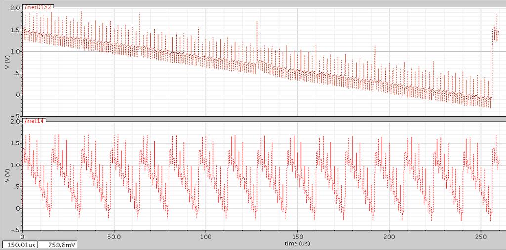
4 V x = V mid V in (4.2 + (2m + lm + l 2(m + l + k + l(m + k V ref where m is the sum of capacitances connected to V ref, and is given as k is the sum of capacitances connected to ground: m = 2 n 2 D n n 3 D n D 1 (4.3 k = 2 n 2 Dn n 3 Dn D 1 + D 0 Sd (4.4 and l = D 0 + D 0 S d (4.5 where n is the number of bits, D n 1... D 0 are the digital inputs, Dn 1... D 0 are their complements, and S d is 1 when the switch S d is closed, and it is zero when the switch is open. By substituting the values of l,m,k, equation (4.2 can be reduced to V x = ( 2 n 2 D n n 3 D n 2... D 1 D 0 2 n n 1 V ref (4.6 (1 + D 0 Note that switches S d and S d1, are controlled by D 0. Switch S d provides an extra capacitance, necessary when the LSB is HIGH. Switch S d takes care that the node V 1 is charged accordingly. For example, if the input bit sequence is 1010, then l = 0, and V x = V mid V in + m V m+k ref = V mid V in + 5V 8 ref, which is the output for a conventional 3-bit DAC with input bits as 101. When the input is 1011, the equivalent circuit would be as shown in Fig For which l = 1 and (2m+lm+l V x = V mid V in + V 2(m+l+k+l(m+k ref = V mid V in + 11V 16 ref. As the above discussion explains, V x in Fig 4.1 is the analog equivalent voltage of the digital input signal, thus demonstrating that this circuit is, in fact, a digital-to-analog converter. 4.2 Simulation results The circuit was laid out and simulated in a 180nm technology, with a V DD of 3 V and a unit capacitor of 100 ff. The layout for an 8-bit DAC is shown in Fig 4.3. Post-layout simulation results are shown in Fig 4.4: A monotonically decreasing digital bit sequence was applied, and the analog output plotted as a function of time. The magnified version of the simulation results with trace markers is shown in Fig 4.6. From the 29
5 Figure 4.3: Equivalent circuit for input trace markers, it is evident that the step sizes are uniform and their value is V DD /2 8. This 8-bit DAC architecture occupies 26 µm 2 area, consumes 6.42 nw at 3 V and has a settling time of 69 ns as opposed to 51 µm 2, 11.8 nw and 136 ns with a conventional DAC architecture with single step switching [31]. The simulated differential non-linearity (DNL and integral non-linearity (INL versus input codes are shown in Fig 4.7 and Fig 4.8, respectively. It can be seen that both INL and DNL are smaller than 0.68 LSB for the entire range of the input code. The dynamic characteristics of the proposed DAC is shown in Fig 4.9. For measuring the dynamic characteristics such as Signal to Noise Ratio (SNR, Spurious Free Dynamic Range (SFDR and Signal to Noise And Distortion (SINAD, an output from an 8-bit ADC is given as the input. SNR and SFDR were simulated with a 240 Hz input sine wave. The corresponding SNR and SFDR were 48.1 db and 52.3 db. 4.3 Comparison with conventional DAC for different switching schemes Table 4.1 shows a comparison of the novel architecture with conventional DACs for power, area and settling time, with different switching schemes discussed in [32]. In the table, a sw is the area of switch and t sw is the switching time for a single transition. The first four rows in the table show the conventional architecture with different switching schemes, employed for reducing 30

6 Figure 4.4: Layout of novel DAC Architecture. Figure 4.5: Post Layout Simulation results. 31
7 Figure 4.6: Magnified version of simulation results. Figure 4.7: Simulated INL versus input codes. 32
8 Figure 4.8: Simulated DNL versus input codes. Figure 4.9: Simulated dynamic performance vs. input. 33
9 Switches schemes Power Delay Area 1 step n( V 2 REF V 2 REF τln(2 n+1 (2 n + (b + 1a sw 2 step n( V 2 REF V 2 REF τln(2 n+1 + t sw 2 n + (b + 1a sw Charge sharing Capacitor splitting Novel DAC n( V 2 REF V 2 REF τln(2 n+1 + t sw 2 n + (2b + 1a sw n( V 2 REF 4 + V 2 REF 4 τln(2 n+1 2 n + (2b + 1a sw n( V 2 REF 8 + 3V 2 REF 8 τ 2 ln(2n+1 (2 n (b + 2a sw Table 4.1: Comparison between the conventional switching schemes and the novel architecture power dissipation. The last row of the table shows the power dissipation, area and speed of the new architecture. The table clearly shows that the new architecture reduces power, area, as well as settling time. A conventional single step switching has been used with the novel architecture. Other switching methods have not been tested with this architecture. Employing other switching methods may improve its performance further. 34
10 4.4 Comparison with the Existing capacitor Array DAC Architectures Three architectures, namely Conventional Binary Weighted Capacitive Array(CBW, Binary Weighted Capacitive Array with attenuation Capacitor(BWA and Split Binary Weighted Capacitive Array(SBW, taken from [ref 1] are compared with the proposed architecture. To have a better comparison between the architectures, the value of the average power consumption, maximum standard deviations of the INL and DNL, and the total capacitance required for each architecture are summarized in table. Standard deviation of INL and DNL for the proposed architecture is calculated using [30] and [47]. Architectures Average Power Standard Deviation of INL Standard Deviation DNL of Total capacitance required CBW N f clk V 2 ref N+1 BWA N/2 f clk V 2 ref N+1 ( N 2 1 σ 2 0 ( 3N 2 1 σ 4 0 ( N 2 1 σ 2 0 ( N 2 σ0 2 2 N ( 3N 2 σ0 4 2 N/2 ( N 2 σ0 2 2C0 2 N SBW N f clk Vref 2 N+1 Proposed DA.59 ( 2 (N f clk Vref 2 ( 2 N 1 σ 2 0 N+1 ( 2 N σ0 2 (2 N Table 4.2: Comparison between the conventional architectures and the novel architecture Derivation For Standard deviation of Integral Non-linearity(INL and Differential Non-linearity(DNL For calculating the linearity characteristics of the proposed scheme, each of the capacitor is modeled as the sum of the nominal capacitance plus the error. C n = 2 n 2 + δ n (4.7 C n 1 = 2 n 3 + δ n 1 (4.8 = + δ 0 (4.9 35
11 The error term = δ n has zero mean and a standard deviation of E[δ 2 n] = 2 n 2 σ 2 0 (4.10 If there are no initial charges, then V x can be expressed as V x = ( b 1 n=1(2 (n 2 + δ n D n ( + δ 0 D 0 + V 2 (b 1 2 (b 1 ref (4.11 ( + ( + δ 0 D 0 Subtracting the nominal value yields the error term V error = which can be approximated as which can be written as with variance ( b 1 n=1 δ n D n δ 0 D 0 + V 2 (b 1 2 (b 1 ref (4.12 ( + ( + δ 0 D 0 V error = From that the worst case INL can be derived as and the worst case DNL be ( b 1 n=1 δ n D n + (C 0 + δ 0 D 0 V 2 (b 1 2 (b ref (4.13 ( bn=1 (δ n D n V error = V 2 (b ref (4.14 E[Verror(y] 2 = y σ0 2 V 2 2 2b C0 2 ref (4.15 σ INL = 2 (b/2 1 σ 0 LSB (4.16 σ DNL = 2 (b/2 σ 0 LSB (4.17 The novel architecture can also be a part of split capacitor array dac, so that the savings in capacitor improves further compared with the normal split capacitor array dac. For example, an 8 bit digital to analog converter with binary weighted capacitor array would require 256 unit capacitors,whereas a split capacitor array would require 31 unit capacitors. If we employ the proposed novel architecture in the split capacitor array, the resultant architecture requires 22 unit capacitors. Fig 4.10, fig 4.11 and fig 4.12 explain the above mentioned concepts. From fig 4.10 it is evident that it requires 31 unit capacitors to implement an 8-bit Digital to Analog converter. Fig 4.11 shows the same 36

12 Figure 4.10: Split-capacitor array DAC and its simulation 37


13 Figure 4.11: Split-Capacitor DAC with proposed Scheme on LSB sub-dac and its simulation 38

14 Figure 4.12: Split-capacitor DAC with proposed scheme on both the sub-dacs 8- bit digital to analog conversion, but uses only 26 unit capacitor. It employs the proposed DAC architecture for its LSB sub-dac. The simulation results show that both the architectures behave in the same way. Fig 4.12 shows the 8-bit conversion with 21 unit capacitors and it employs the proposed architecture for both the LSB and MSB sub-dacs. 4.5 Design Considerations In this section we consider the effects of Capacitor parasitics and Capacitor mismatches Capacitor Parasitics Case 1 : A Parasitic Capacitance (C p at V 1, would result in the following circuit. Using the Star- Delta conversion an equivalent would be generated as shown in fig Where C 1 = m + ml + l l (4.18 C 2 = m + ml + l m (
15 Figure 4.13: Generalized equivalent circuit with parasitic capacitance. Figure 4.14: Equivalent circuit with a Delta-Star conversion C 3 = m + ml + l (4.20 From Fig 4.14, with equations (4.18, (4.19 and (4.20, V 1 can be written as V 1 = V ref C 1 C 1 + C 2 C C p + C 3 (4.21 C 3 + while substituting (4.18, (4.19 and (4.20 in equation (4.21 V 1 = ( V mc0 +ml +l ref l ( (4.22 mc0 +ml +l ( l + m +ml +l m + C ( m +ml +l p + (m+ml +l m + (m +ml +l + 40
16 Node voltage V x can be written as V x = V x can be written as in (4.24, while substuting (4.22 in (4.21 V x = ( m + ml + l m + ml + l + 1 ( m + ml + l V 1 (4.23 m + ml + l + 1 ( V mc0 +ml +l ref l ( mc0 +ml +l ( m +ml +l l + m + C ( m +ml +l p + (m+ml +l m + (m +ml +l + The following example would illustrate the effect of C p at V x. (4.24 Consider a bit pattern of for a 5-bit digital to analog conversion with m = 14, l=2. Now V x can be calculated as For the next bit pattern The difference in these two generated voltage is ( 1276 V x = V ref C p (4.25 ( 29 V x = V ref C p (4.26 V x = V ref (4.27 V x1 V x2 = 15 ( 16 V 29 ref V ref ( C p In the above equation, if C p = 0, then the difference is (1/32V ref which is V ref /2 n. If C p / = 0.5 then the difference in two consecutive generated voltage is (1/22V ref which is well within 0.5LSB. This explanation shows that the Parasitic capacitance at V 1 will not affect the static characteristics of the proposed DAC. Case 2 : If there is an additional parasitic capacitance from V DD to V 1 : The generalized equivalent diagram would be as shown in fig The generalized voltage at V x is V x = m( + C p + ml(c p + + l m(c p + C0 + ml(c p + + l + (4.29 ( m(c0 +C p+ml( +C p+l l + ( m(c0 +C V p+ml( +C p+l ref ( m(c0 +Cp+ml( +Cp +lc 0 2 m( +Cp ( mc0 ( +Cp+ml( +Cp +lc 0 2 m( +Cp l + + C p + (m(+c p+ml( +C p+l (m( +C p+ml( +C p+l + 41
17 Figure 4.15: Equivalent circuit with parasitic capacitance For a five bit digital to analog conversion, with a bit pattern of 11101, m = 14, l=2 and for (C p / = 0.5. From these values V x can be calculated as V x1 = V ref (4.30 For 11110, V x can be generated as The difference between the two subsequently generated voltage is Which is well within 0.5LSB. V x2 = V ref (4.31 V x2 V x1 = V ref (4.32 Fig and 4.17 plots the impact of Cp on DAC linearity for an 8-bit DAC. The peak-to-peak INL of the DAC is plotted against the ratio Cp/Cu and the corresponding DNL and INL plots for when Cp/Cu is 0.1 and 0.5 are also plotted. As the plots show, in order to get an INL below +/-0.5 LSB, the unit capacitance,, should be about 2x larger than the parasitic cap at the output node Capacitor mismatches The novel architecture employs 3 additional capacitances, which are the same as the unit capacitance. So the required matching ratio compared with the unit capacitor is 1:1. This makes the 42


18 Figure 4.16: DNL for capacitor parasitics Figure 4.17: INL for capacitor parasitics 43

19 design less prone to capacitance mismatches. The impact of these random variations in captured in Fig.4.18 which plots the INL of an 8-bit DAC for 3σ variation of 5 %. As the plot shows, the DAC shows a fairly muted response even to significantly large random per unit capacitor variations. Figure 4.18: INL for randomly mismatched capacitor 44
EE 435. Lecture 26. Data Converters. Data Converter Characterization
 EE 435 Lecture 26 Data Converters Data Converter Characterization . Review from last lecture. Data Converter Architectures n DAC R-2R (4-bits) R R R R V OUT 2R 2R 2R 2R R d 3 d 2 d 1 d 0 V REF By superposition:
EE247 Lecture 16. Serial Charge Redistribution DAC
 EE47 Lecture 16 D/A Converters D/A examples Serial charge redistribution DAC Practical aspects of current-switch DACs Segmented current-switch DACs DAC self calibration techniques Current copiers Dynamic
Data Converter Fundamentals
 Data Converter Fundamentals David Johns and Ken Martin (johns@eecg.toronto.edu) (martin@eecg.toronto.edu) slide 1 of 33 Introduction Two main types of converters Nyquist-Rate Converters Generate output
PARALLEL DIGITAL-ANALOG CONVERTERS
 CMOS Analog IC Design Page 10.2-1 10.2 - PARALLEL DIGITAL-ANALOG CONVERTERS CLASSIFICATION OF DIGITAL-ANALOG CONVERTERS CMOS Analog IC Design Page 10.2-2 CURRENT SCALING DIGITAL-ANALOG CONVERTERS GENERAL
Research Article Linearity Analysis on a Series-Split Capacitor Array for High-Speed SAR ADCs
 Hindawi Publishing Corporation LSI Design olume 1, Article ID 76548, 8 pages doi:1.1155/1/76548 Research Article Linearity Analysis on a Series-Split Capacitor Array for High-Speed SAR ADCs Yan Zhu, 1
A Modeling Environment for the Simulation and Design of Charge Redistribution DACs Used in SAR ADCs
 204 UKSim-AMSS 6th International Conference on Computer Modelling and Simulation A Modeling Environment for the Simulation and Design of Charge Redistribution DACs Used in SAR ADCs Stefano Brenna, Andrea
Nyquist-Rate D/A Converters. D/A Converter Basics.
 Nyquist-Rate D/A Converters David Johns and Ken Martin (johns@eecg.toronto.edu) (martin@eecg.toronto.edu) slide 1 of 20 D/A Converter Basics. B in D/A is a digital signal (or word), B in b i B in = 2 1
EXTENDING THE RESOLUTION OF PARALLEL DIGITAL-ANALOG CONVERTERS
 CMOS Analog IC Design Page 10.3-1 10.3 - EXTENDING THE RESOLUTION OF PARALLEL DIGITAL-ANALOG CONVERTERS TECHNIQUE: Divide the total resolution N into k smaller sub-dacs each with a resolution of N k. Result:
D/A Converters. D/A Examples
 D/A architecture examples Unit element Binary weighted Static performance Component matching Architectures Unit element Binary weighted Segmented Dynamic element matching Dynamic performance Glitches Reconstruction
Successive Approximation ADCs
 Department of Electrical and Computer Engineering Successive Approximation ADCs Vishal Saxena Vishal Saxena -1- Successive Approximation ADC Vishal Saxena -2- Data Converter Architectures Resolution [Bits]
ir. Georgi Radulov 1, dr. ir. Patrick Quinn 2, dr. ir. Hans Hegt 1, prof. dr. ir. Arthur van Roermund 1 Eindhoven University of Technology Xilinx
 Calibration of Current Steering D/A Converters ir. eorgi Radulov 1, dr. ir. Patrick Quinn 2, dr. ir. Hans Hegt 1, prof. dr. ir. Arthur van Roermund 1 1 Eindhoven University of Technology 2 Xilinx Current-steering
EE 435. Lecture 26. Data Converters. Data Converter Characterization
 EE 435 Lecture 26 Data Converters Data Converter Characterization . Review from last lecture. Data Converter Architectures Large number of different circuits have been proposed for building data converters
Pipelined multi step A/D converters
 Department of Electrical Engineering Indian Institute of Technology, Madras Chennai, 600036, India 04 Nov 2006 Motivation for multi step A/D conversion Flash converters: Area and power consumption increase
Analog and Telecommunication Electronics
 Politecnico di Torino Electronic Eng. Master Degree Analog and Telecommunication Electronics D2 - DAC taxonomy and errors» Static and dynamic parameters» DAC taxonomy» DAC circuits» Error sources AY 2015-16
Behavioral Model of Split Capacitor Array DAC for Use in SAR ADC Design
 Behavioral Model of Split Capacitor Array DAC for Use in SAR ADC Design PC.SHILPA 1, M.H PRADEEP 2 P.G. Scholar (M. Tech), Dept. of ECE, BITIT College of Engineering, Anantapur Asst Professor, Dept. of
BEHAVIORAL MODEL OF SPLIT CAPACITOR ARRAY DAC FOR USE IN SAR ADC DESIGN
 BEHAVIORAL MODEL OF SPLIT CAPACITOR ARRAY DAC FOR USE IN SAR ADC DESIGN 1 P C.SHILPA, 2 M.H PRADEEP 1 P.G. Scholar (M. Tech), Dept. of ECE, BITIT College of Engineering, Anantapur 2 Asst Professor, Dept.
Successive approximation time-to-digital converter based on vernier charging method
 LETTER Successive approximation time-to-digital converter based on vernier charging method Xin-Gang Wang 1, 2, Hai-Gang Yang 1a), Fei Wang 1, and Hui-He 2 1 Institute of Electronics, Chinese Academy of
The influence of parasitic capacitors on SAR ADC characteristics
 The influence of parasitic capacitors on SAR ADC characteristics DMITRY NORMANOV, DMITRY OSIPOV National Research Nuclear University MEPHI ASIC Lab 59, Moscow, Kashirskoe shosse, 3 RUSSIA simplere@ya.ru
Slide Set Data Converters. Digital Enhancement Techniques
 0 Slide Set Data Converters Digital Enhancement Techniques Introduction Summary Error Measurement Trimming of Elements Foreground Calibration Background Calibration Dynamic Matching Decimation and Interpolation
ELEC516 Digital VLSI System Design and Design Automation (spring, 2010) Assignment 4 Reference solution
 Assignment 4 Reference solution") ELEC516 Digital VLSI System Design and Design Automation (spring, 010) Assignment 4 Reference solution 1) Pulse-plate 1T DRAM cell a) Timing diagrams for nodes and Y when writing 0 and 1 Timing diagram
ELEC516 Digital VLSI System Design and Design Automation (spring, 010) Assignment 4 Reference solution 1) Pulse-plate 1T DRAM cell a) Timing diagrams for nodes and Y when writing 0 and 1 Timing diagram
EE 435. Lecture 36. Quantization Noise ENOB Absolute and Relative Accuracy DAC Design. The String DAC
 EE 435 Lecture 36 Quantization Noise ENOB Absolute and elative Accuracy DAC Design The String DAC . eview from last lecture. Quantization Noise in ADC ecall: If the random variable f is uniformly distributed
Power Dissipation. Where Does Power Go in CMOS?
 Power Dissipation [Adapted from Chapter 5 of Digital Integrated Circuits, 2003, J. Rabaey et al.] Where Does Power Go in CMOS? Dynamic Power Consumption Charging and Discharging Capacitors Short Circuit
EE115C Digital Electronic Circuits Homework #4
 EE115 Digital Electronic ircuits Homework #4 Problem 1 Power Dissipation Solution Vdd =1.0V onsider the source follower circuit used to drive a load L =20fF shown above. M1 and M2 are both NMOS transistors
EE 435. Lecture 26. Data Converters. Differential Nonlinearity Spectral Performance
 EE 435 Lecture 26 Data Converters Differential Nonlinearity Spectral Performance . Review from last lecture. Integral Nonlinearity (DAC) Nonideal DAC INL often expressed in LSB INL = X k INL= max OUT OF
Lecture 340 Characterization of DACs and Current Scaling DACs (5/1/10) Page 340-1
 Page 340-1") Lecture 34 Characterization of DACs and Current Scaling DACs (5//) Page 34 LECTURE 34 CHARACTERZATON OF DACS AND CURRENT SCALNG DACS LECTURE ORGANZATON Outline ntroduction Static characterization of DACs
Lecture 34 Characterization of DACs and Current Scaling DACs (5//) Page 34 LECTURE 34 CHARACTERZATON OF DACS AND CURRENT SCALNG DACS LECTURE ORGANZATON Outline ntroduction Static characterization of DACs
EE 435. Lecture 38. DAC Design Current Steering DACs Charge Redistribution DACs ADC Design
 EE 435 Lecture 38 DAC Design Current Steering DACs Charge edistribution DACs ADC Design eview from last lecture Current Steering DACs X N Binary to Thermometer ndecoder (all ON) S S N- S N V EF F nherently
EECS 141: FALL 05 MIDTERM 1
 University of California College of Engineering Department of Electrical Engineering and Computer Sciences D. Markovic TuTh 11-1:3 Thursday, October 6, 6:3-8:pm EECS 141: FALL 5 MIDTERM 1 NAME Last SOLUTION
Lecture 6 Power Zhuo Feng. Z. Feng MTU EE4800 CMOS Digital IC Design & Analysis 2010
 EE4800 CMOS Digital IC Design & Analysis Lecture 6 Power Zhuo Feng 6.1 Outline Power and Energy Dynamic Power Static Power 6.2 Power and Energy Power is drawn from a voltage source attached to the V DD
Nyquist-Rate A/D Converters
 IsLab Analog Integrated ircuit Design AD-51 Nyquist-ate A/D onverters כ Kyungpook National University IsLab Analog Integrated ircuit Design AD-1 Nyquist-ate MOS A/D onverters Nyquist-rate : oversampling
Analog and Telecommunication Electronics
 Politecnico di Torino - ICT School Analog and Telecommunication Electronics D3 - A/D converters» Error taxonomy» ADC parameters» Structures and taxonomy» Mixed converters» Origin of errors 12/05/2011-1
A Novel LUT Using Quaternary Logic
 A Novel LUT Using Quaternary Logic 1*GEETHA N S 2SATHYAVATHI, N S 1Department of ECE, Applied Electronics, Sri Balaji Chockalingam Engineering College, Arani,TN, India. 2Assistant Professor, Department
9/18/2008 GMU, ECE 680 Physical VLSI Design
 ECE680: Physical VLSI Design Chapter III CMOS Device, Inverter, Combinational circuit Logic and Layout Part 3 Combinational Logic Gates (textbook chapter 6) 9/18/2008 GMU, ECE 680 Physical VLSI Design
Chapter 8. Low-Power VLSI Design Methodology
 VLSI Design hapter 8 Low-Power VLSI Design Methodology Jin-Fu Li hapter 8 Low-Power VLSI Design Methodology Introduction Low-Power Gate-Level Design Low-Power Architecture-Level Design Algorithmic-Level
COMP 103. Lecture 16. Dynamic Logic
 COMP 03 Lecture 6 Dynamic Logic Reading: 6.3, 6.4 [ll lecture notes are adapted from Mary Jane Irwin, Penn State, which were adapted from Rabaey s Digital Integrated Circuits, 2002, J. Rabaey et al.] COMP03
Digital to Analog Converters I
 Advanced Analog Building Blocks 2 Digital to Analog Converters I Albert Comerma (PI) (comerma@physi.uni-heidelberg.de) Course web WiSe 2017 DAC parameters DACs parameters DACs non ideal effects DACs performance
Extremely small differential non-linearity in a DMOS capacitor based cyclic ADC for CMOS image sensors
 Extremely small differential non-linearity in a DMOS capacitor based cyclic ADC for CMOS image sensors Zhiheng Wei 1a), Keita Yasutomi ) and Shoji Kawahito b) 1 Graduate School of Science and Technology,
Name: Answers. Mean: 83, Standard Deviation: 12 Q1 Q2 Q3 Q4 Q5 Q6 Total. ESE370 Fall 2015
 University of Pennsylvania Department of Electrical and System Engineering Circuit-Level Modeling, Design, and Optimization for Digital Systems ESE370, Fall 2015 Final Tuesday, December 15 Problem weightings
8-bit 50ksps ULV SAR ADC
 8-bit 50ksps ULV SAR ADC Fredrik Hilding Rosenberg Master of Science in Electronics Submission date: June 2015 Supervisor: Trond Ytterdal, IET Norwegian University of Science and Technology Department
A Nonuniform Quantization Scheme for High Speed SAR ADC Architecture
 A Nonuniform Quantization Scheme for High Speed SAR ADC Architecture Youngchun Kim Electrical and Computer Engineering The University of Texas Wenjuan Guo Intel Corporation Ahmed H Tewfik Electrical and
Modeling All-MOS Log-Domain Σ A/D Converters
 DCIS 04 Modeling All-MOS Log Σ ADCs Intro Circuits Modeling Example Conclusions 1/22 Modeling All-MOS Log-Domain Σ A/D Converters X.Redondo 1, J.Pallarès 2 and F.Serra-Graells 1 1 Institut de Microelectrònica
EE141Microelettronica. CMOS Logic
 Microelettronica CMOS Logic CMOS logic Power consumption in CMOS logic gates Where Does Power Go in CMOS? Dynamic Power Consumption Charging and Discharging Capacitors Short Circuit Currents Short Circuit
Switched Capacitor Circuits II. Dr. Paul Hasler Georgia Institute of Technology
 Switched Capacitor Circuits II Dr. Paul Hasler Georgia Institute of Technology Basic Switch-Cap Integrator = [n-1] - ( / ) H(jω) = - ( / ) 1 1 - e -jωt ~ - ( / ) / jωt (z) - z -1 1 (z) = H(z) = - ( / )
Lab 3 Revisited. Zener diodes IAP 2008 Lecture 4 1
 Lab 3 Revisited Zener diodes R C 6.091 IAP 2008 Lecture 4 1 Lab 3 Revisited +15 Voltage regulators 555 timers 270 1N758 0.1uf 5K pot V+ V- 2N2222 0.1uf V o. V CC V Vin s = 5 V Vc V c Vs 1 e t = RC Threshold
DAC10* PRODUCT PAGE QUICK LINKS Last Content Update: 02/23/2017
 * PRODUCT PAGE QUICK LINKS Last Content Update: 0/3/07 COMPARABLE PARTS View a parametric search of comparable parts. DOCUMENTATION Data Sheet : 0-Bit Current-Out DAC Data Sheet REFERENCE MATERIALS Solutions
EE 435. Lecture 29. Data Converters. Linearity Measures Spectral Performance
 EE 435 Lecture 9 Data Converters Linearity Measures Spectral Performance Linearity Measurements (testing) Consider ADC V IN (t) DUT X IOUT V REF Linearity testing often based upon code density testing
ESE 570: Digital Integrated Circuits and VLSI Fundamentals
 ESE 570: Digital Integrated Circuits and VLSI Fundamentals Lec 19: March 29, 2018 Memory Overview, Memory Core Cells Today! Charge Leakage/Charge Sharing " Domino Logic Design Considerations! Logic Comparisons!
EE 521: Instrumentation and Measurements
 Aly El-Osery Electrical Engineering Department, New Mexico Tech Socorro, New Mexico, USA September 23, 2009 1 / 18 1 Sampling 2 Quantization 3 Digital-to-Analog Converter 4 Analog-to-Digital Converter
EE 466/586 VLSI Design. Partha Pande School of EECS Washington State University
 EE 466/586 VLSI Design Partha Pande School of EECS Washington State University pande@eecs.wsu.edu Lecture 8 Power Dissipation in CMOS Gates Power in CMOS gates Dynamic Power Capacitance switching Crowbar
CMOS Digital Integrated Circuits Lec 13 Semiconductor Memories
 Lec 13 Semiconductor Memories 1 Semiconductor Memory Types Semiconductor Memories Read/Write (R/W) Memory or Random Access Memory (RAM) Read-Only Memory (ROM) Dynamic RAM (DRAM) Static RAM (SRAM) 1. Mask
EEC 216 Lecture #3: Power Estimation, Interconnect, & Architecture. Rajeevan Amirtharajah University of California, Davis
 EEC 216 Lecture #3: Power Estimation, Interconnect, & Architecture Rajeevan Amirtharajah University of California, Davis Outline Announcements Review: PDP, EDP, Intersignal Correlations, Glitching, Top
Design for Manufacturability and Power Estimation. Physical issues verification (DSM)
") Design for Manufacturability and Power Estimation Lecture 25 Alessandra Nardi Thanks to Prof. Jan Rabaey and Prof. K. Keutzer Physical issues verification (DSM) Interconnects Signal Integrity P/G integrity
Design for Manufacturability and Power Estimation Lecture 25 Alessandra Nardi Thanks to Prof. Jan Rabaey and Prof. K. Keutzer Physical issues verification (DSM) Interconnects Signal Integrity P/G integrity
ADC Bit, 50MHz Video A/D Converter
 ADC- -Bit, 0MHz Video A/D Converter FEATURES Low power dissipation (0mW max.) Input signal bandwith (00MHz) Optional synchronized clamp function Low input capacitance (pf typ.) +V or +V /+.V power supply
EE 505 Lecture 7. Spectral Performance of Data Converters - Time Quantization - Amplitude Quantization Clock Jitter Statistical Circuit Modeling
 EE 505 Lecture 7 Spectral Performance of Data Converters - Time Quantization - Amplitude Quantization Clock Jitter Statistical Circuit Modeling . Review from last lecture. MatLab comparison: 512 Samples
Last Lecture. Power Dissipation CMOS Scaling. EECS 141 S02 Lecture 8
 EECS 141 S02 Lecture 8 Power Dissipation CMOS Scaling Last Lecture CMOS Inverter loading Switching Performance Evaluation Design optimization Inverter Sizing 1 Today CMOS Inverter power dissipation» Dynamic»
Spiral 2 7. Capacitance, Delay and Sizing. Mark Redekopp
 2-7.1 Spiral 2 7 Capacitance, Delay and Sizing Mark Redekopp 2-7.2 Learning Outcomes I understand the sources of capacitance in CMOS circuits I understand how delay scales with resistance, capacitance
EEO 401 Digital Signal Processing Prof. Mark Fowler
 EEO 401 Digital Signal Processing Pro. Mark Fowler Note Set #14 Practical A-to-D Converters and D-to-A Converters Reading Assignment: Sect. 6.3 o Proakis & Manolakis 1/19 The irst step was to see that
CARNEGIE MELLON UNIVERSITY DEPARTMENT OF ELECTRICAL AND COMPUTER ENGINEERING DIGITAL INTEGRATED CIRCUITS FALL 2002
 CARNEGIE MELLON UNIVERSITY DEPARTMENT OF ELECTRICAL AND COMPUTER ENGINEERING 18-322 DIGITAL INTEGRATED CIRCUITS FALL 2002 Final Examination, Monday Dec. 16, 2002 NAME: SECTION: Time: 180 minutes Closed
THE INVERTER. Inverter
 THE INVERTER DIGITAL GATES Fundamental Parameters Functionality Reliability, Robustness Area Performance» Speed (delay)» Power Consumption» Energy Noise in Digital Integrated Circuits v(t) V DD i(t) (a)
ESE 570: Digital Integrated Circuits and VLSI Fundamentals
 ESE 570: Digital Integrated Circuits and VLSI Fundamentals Lec 24: April 19, 2018 Crosstalk and Wiring, Transmission Lines Lecture Outline! Crosstalk! Repeaters in Wiring! Transmission Lines " Where transmission
! Charge Leakage/Charge Sharing. " Domino Logic Design Considerations. ! Logic Comparisons. ! Memory. " Classification. " ROM Memories.
 ESE 57: Digital Integrated Circuits and VLSI Fundamentals Lec 9: March 9, 8 Memory Overview, Memory Core Cells Today! Charge Leakage/ " Domino Logic Design Considerations! Logic Comparisons! Memory " Classification
EE241 - Spring 2000 Advanced Digital Integrated Circuits. References
 EE241 - Spring 2000 Advanced Digital Integrated Circuits Lecture 26 Memory References Rabaey, Digital Integrated Circuits Memory Design and Evolution, VLSI Circuits Short Course, 1998.» Gillingham, Evolution
! Crosstalk. ! Repeaters in Wiring. ! Transmission Lines. " Where transmission lines arise? " Lossless Transmission Line.
 ESE 570: Digital Integrated Circuits and VLSI Fundamentals Lec 24: April 19, 2018 Crosstalk and Wiring, Transmission Lines Lecture Outline! Crosstalk! Repeaters in Wiring! Transmission Lines " Where transmission
Lecture 7 Circuit Delay, Area and Power
 Lecture 7 Circuit Delay, Area and Power lecture notes from S. Mitra Intro VLSI System course (EE271) Introduction to VLSI Systems 1 Circuits and Delay Introduction to VLSI Systems 2 Power, Delay and Area:
ESE 570: Digital Integrated Circuits and VLSI Fundamentals
 ESE 570: Digital Integrated Circuits and VLSI Fundamentals Lec 18: March 27, 2018 Dynamic Logic, Charge Injection Lecture Outline! Sequential MOS Logic " D-Latch " Timing Constraints! Dynamic Logic " Domino
A 74.9 db SNDR 1 MHz Bandwidth 0.9 mw Delta-Sigma Time-to-Digital Converter Using Charge Pump and SAR ADC
 A 74.9 db SNDR 1 MHz Bandwidth 0.9 mw Delta-Sigma Time-to-Digital Converter Using Charge Pump and SAR ADC Anugerah Firdauzi, Zule Xu, Masaya Miyahara, and Akira Matsuzawa Tokyo Institute of Technology,
EE 505. Lecture 27. ADC Design Pipeline
 EE 505 Lecture 7 AD Design Pipeline Review Sampling Noise V n5 R S5 dv REF V n4 R S4 V ns V ns β= + If the ON impedance of the switches is small and it is assumed that = =, it can be shown that Vˆ IN-RMS
Summary Last Lecture
 EE247 Lecture 19 ADC Converters Sampling (continued) Sampling switch charge injection & clock feedthrough Complementary switch Use of dummy device Bottom-plate switching Track & hold T/H circuits T/H combined
High-Speed, High-Resolution, Radiation-Tolerant SAR ADC for Particle Physics Experiments
 Erik Jonsson School of Engineering & Computer Science High-Speed, High-Resolution, Radiation-Tolerant SAR ADC for Particle Physics Experiments Yun Chiu Erik Jonsson Distinguished Professor Texas Analog
Digital Integrated Circuits A Design Perspective
 Digital Integrated Circuits Design Perspective Designing Combinational Logic Circuits Fuyuzhuo School of Microelectronics,SJTU Introduction Digital IC Dynamic Logic Introduction Digital IC 2 EE141 Dynamic
Topics. Dynamic CMOS Sequential Design Memory and Control. John A. Chandy Dept. of Electrical and Computer Engineering University of Connecticut
 Topics Dynamic CMOS Sequential Design Memory and Control Dynamic CMOS In static circuits at every point in time (except when switching) the output is connected to either GND or V DD via a low resistance
Digital Integrated Circuits A Design Perspective
 Semiconductor Memories Adapted from Chapter 12 of Digital Integrated Circuits A Design Perspective Jan M. Rabaey et al. Copyright 2003 Prentice Hall/Pearson Outline Memory Classification Memory Architectures
EE141-Fall 2011 Digital Integrated Circuits
 EE4-Fall 20 Digital Integrated Circuits Lecture 5 Memory decoders Administrative Stuff Homework #6 due today Project posted Phase due next Friday Project done in pairs 2 Last Lecture Last lecture Logical
Signal integrity in deep-sub-micron integrated circuits
 Signal integrity in deep-sub-micron integrated circuits Alessandro Bogliolo abogliolo@ing.unife.it Outline Introduction General signaling scheme Noise sources and effects in DSM ICs Supply noise Synchronization
ESE570 Spring University of Pennsylvania Department of Electrical and System Engineering Digital Integrated Cicruits AND VLSI Fundamentals
 University of Pennsylvania Department of Electrical and System Engineering Digital Integrated Cicruits AND VLSI Fundamentals ESE570, Spring 017 Final Wednesday, May 3 4 Problems with point weightings shown.
Lecture 10, ATIK. Data converters 3
 Lecture, ATIK Data converters 3 What did we do last time? A quick glance at sigma-delta modulators Understanding how the noise is shaped to higher frequencies DACs A case study of the current-steering
ECE 407 Computer Aided Design for Electronic Systems. Simulation. Instructor: Maria K. Michael. Overview
 407 Computer Aided Design for Electronic Systems Simulation Instructor: Maria K. Michael Overview What is simulation? Design verification Modeling Levels Modeling circuits for simulation True-value simulation
ΗΜΥ 307 ΨΗΦΙΑΚΑ ΟΛΟΚΛΗΡΩΜΕΝΑ ΚΥΚΛΩΜΑΤΑ Εαρινό Εξάμηνο 2018
 ΗΜΥ 307 ΨΗΦΙΑΚΑ ΟΛΟΚΛΗΡΩΜΕΝΑ ΚΥΚΛΩΜΑΤΑ Εαρινό Εξάμηνο 2018 ΔΙΑΛΕΞΗ 11: Dynamic CMOS Circuits ΧΑΡΗΣ ΘΕΟΧΑΡΙΔΗΣ (ttheocharides@ucy.ac.cy) (ack: Prof. Mary Jane Irwin and Vijay Narayanan) [Προσαρμογή από
MAHARASHTRA STATE BOARD OF TECHNICAL EDUCATION (Autonomous) (ISO/IEC Certified) State any two Boolean laws. (Any 2 laws 1 mark each)
 (ISO/IEC Certified) State any two Boolean laws. (Any 2 laws 1 mark each)") Subject Code: 17333 Model Answer Page 1/ 27 Important Instructions to examiners: 1) The answers should be examined by key words and not as word-to-word as given in the model answer scheme. 2) The model
Subject Code: 17333 Model Answer Page 1/ 27 Important Instructions to examiners: 1) The answers should be examined by key words and not as word-to-word as given in the model answer scheme. 2) The model
SWITCHED CAPACITOR AMPLIFIERS
 SWITCHED CAPACITOR AMPLIFIERS AO 0V 4. AO 0V 4.2 i Q AO 0V 4.3 Q AO 0V 4.4 Q i AO 0V 4.5 AO 0V 4.6 i Q AO 0V 4.7 Q AO 0V 4.8 i Q AO 0V 4.9 Simple amplifier First approach: A 0 = infinite. C : V C = V s
EE 435. Lecture 28. Data Converters Linearity INL/DNL Spectral Performance
 EE 435 Lecture 8 Data Converters Linearity INL/DNL Spectral Performance Performance Characterization of Data Converters Static characteristics Resolution Least Significant Bit (LSB) Offset and Gain Errors
Lecture 23. Dealing with Interconnect. Impact of Interconnect Parasitics
 Lecture 23 Dealing with Interconnect Impact of Interconnect Parasitics Reduce Reliability Affect Performance Classes of Parasitics Capacitive Resistive Inductive 1 INTERCONNECT Dealing with Capacitance
Next, we check the race condition to see if the circuit will work properly. Note that the minimum logic delay is a single sum.
 UNIVERSITY OF CALIFORNIA College of Engineering Department of Electrical Engineering and Computer Sciences Last modified on May 1, 2003 by Dejan Markovic (dejan@eecs.berkeley.edu) Prof. Jan Rabaey EECS
EE241 - Spring 2001 Advanced Digital Integrated Circuits
 EE241 - Spring 21 Advanced Digital Integrated Circuits Lecture 12 Low Power Design Self-Resetting Logic Signals are pulses, not levels 1 Self-Resetting Logic Sense-Amplifying Logic Matsui, JSSC 12/94 2
Lecture 8-1. Low Power Design
 Lecture 8 Konstantinos Masselos Department of Electrical & Electronic Engineering Imperial College London URL: http://cas.ee.ic.ac.uk/~kostas E-mail: k.masselos@ic.ac.uk Lecture 8-1 Based on slides/material
UNIVERSITY OF CALIFORNIA, BERKELEY College of Engineering Department of Electrical Engineering and Computer Sciences
 UNIVERSITY OF LIFORNI, ERKELEY ollege of Engineering Department of Electrical Engineering and omputer Sciences Elad lon Homework #3 EE141 Due Thursday, September 13 th, 5pm, box outside 125 ory PROLEM
EECS 141 F01 Lecture 17
 EECS 4 F0 Lecture 7 With major inputs/improvements From Mary-Jane Irwin (Penn State) Dynamic CMOS In static circuits at every point in time (except when switching) the output is connected to either GND
Laboratory-on-chip based sensors Part 2: Capacitive measurements
 GBM8320 Dispositifs Médicaux Intelligents Laboratory-on-chip based sensors Part 2: Capacitive measurements Mohamad Sawan et al. Laboratoire de neurotechnologies Polystim!!! http://www.cours.polymtl.ca/gbm8320/!
CMPEN 411 VLSI Digital Circuits Spring Lecture 14: Designing for Low Power
 CMPEN 411 VLSI Digital Circuits Spring 2012 Lecture 14: Designing for Low Power [Adapted from Rabaey s Digital Integrated Circuits, Second Edition, 2003 J. Rabaey, A. Chandrakasan, B. Nikolic] Sp12 CMPEN
MOSIS REPORT. Report:
 MOSIS REPORT Report: 1. Report 1 2. Report 2 3. Report 3 Report 1 The most important step in designing a four-bit counter is determining what type of flipflop to use. Almost any type of flip-flop can be
Switched-Capacitor Circuits David Johns and Ken Martin University of Toronto
 Switched-Capacitor Circuits David Johns and Ken Martin University of Toronto (johns@eecg.toronto.edu) (martin@eecg.toronto.edu) University of Toronto 1 of 60 Basic Building Blocks Opamps Ideal opamps usually
MOSIS REPORT. Spring MOSIS Report 1. MOSIS Report 2. MOSIS Report 3
 MOSIS REPORT Spring 2010 MOSIS Report 1 MOSIS Report 2 MOSIS Report 3 MOSIS Report 1 Design of 4-bit counter using J-K flip flop I. Objective The purpose of this project is to design one 4-bit counter
ECE321 Electronics I
 ECE321 Electronics I Lecture 1: Introduction to Digital Electronics Payman Zarkesh-Ha Office: ECE Bldg. 230B Office hours: Tuesday 2:00-3:00PM or by appointment E-mail: payman@ece.unm.edu Slide: 1 Textbook
24.2: Self-Biased, High-Bandwidth, Low-Jitter 1-to-4096 Multiplier Clock Generator PLL
 24.2: Self-Biased, High-Bandwidth, Low-Jitter 1-to-4096 Multiplier Clock Generator PLL John G. Maneatis 1, Jaeha Kim 1, Iain McClatchie 1, Jay Maxey 2, Manjusha Shankaradas 2 True Circuits, Los Altos,
An Anti-Aliasing Multi-Rate Σ Modulator
 An Anti-Aliasing Multi-Rate Σ Modulator Anthony Chan Carusone Depart. of Elec. and Comp. Eng. University of Toronto, Canada Franco Maloberti Department of Electronics University of Pavia, Italy May 6,
Lecture Outline. ESE 570: Digital Integrated Circuits and VLSI Fundamentals. Review: 1st Order RC Delay Models. Review: Two-Input NOR Gate (NOR2)
") ESE 570: Digital Integrated Circuits and VLSI Fundamentals Lec 14: March 1, 2016 Combination Logic: Ratioed and Pass Logic Lecture Outline! CMOS Gates Review " CMOS Worst Case Analysis! Ratioed Logic Gates!
ESE 570: Digital Integrated Circuits and VLSI Fundamentals Lec 14: March 1, 2016 Combination Logic: Ratioed and Pass Logic Lecture Outline! CMOS Gates Review " CMOS Worst Case Analysis! Ratioed Logic Gates!
ESE 570: Digital Integrated Circuits and VLSI Fundamentals
 ESE 570: Digital Integrated Circuits and VLSI Fundamentals Lec 23: April 17, 2018 I/O Circuits, Inductive Noise, CLK Generation Lecture Outline! Packaging! Variation and Testing! I/O Circuits! Inductive
Top-Down Design of a xdsl 14-bit 4MS/s Σ Modulator in Digital CMOS Technology
 Top-Down Design of a xdsl -bit 4MS/s Σ Modulator in Digital CMOS Technology R. del Río, J.M. de la Rosa, F. Medeiro, B. Pérez-Verdú, and A. Rodríguez-Vázquez Instituto de Microelectrónica de Sevilla CNM-CSIC
Topics to be Covered. capacitance inductance transmission lines
 Topics to be Covered Circuit Elements Switching Characteristics Power Dissipation Conductor Sizes Charge Sharing Design Margins Yield resistance capacitance inductance transmission lines Resistance of
NOISE-SHAPING SAR ADCS
 NOISE-SHAPING SAR ADCS by Jeffrey Alan Fredenburg A dissertation submitted in partial fulfillment of the requirements for the degree of Doctor of Philosophy (Electrical Engineering) in the University of
Preamplifier in 0.5µm CMOS
 A 2.125 Gbaud 1.6kΩ Transimpedance Preamplifier in 0.5µm CMOS Sunderarajan S. Mohan Thomas H. Lee Center for Integrated Systems Stanford University OUTLINE Motivation Shunt-peaked Amplifier Inductor Modeling