Synchronous Sequential Logic. Chapter 5
|
|
|
- May Doyle
- 6 years ago
- Views:
Transcription
1 Synchronous Sequential Logic Chapter 5
2
3
4
5
6
7
8
9
10
11
12
13
14
15
16
17
18
19
20
21
22
23
24 Other Flip Flops D flip flops requires smallest number of gates. Thus, they are commonly used Other flip flops are JK flip flops T flip flops
25 Three operations of flip flops Three operations that can be performed with flip flops are Set it to 1 Reset it to 0 Complement its output D flip flop can only set and reset JK has two inputs and can perform all three operations
26 JK flip flop J input sets to 1 K input resets to 0 When both inputs are enabled, output is complemented.
27 JK flip flop The function of the D input: D=JQ +K Q When J=1 AND K=0, D=Q +Q=1 When J=0 AND K=1, D=0 When J=1 AND K=1, D=Q (complemented) When J=0 AND K=0, D=Q (unchanged)

, no change When T=1")
 D T Q TQ T Q When")
28 T (toggle) flip flop It is a complementing ff. J and K are tied together (Fig a) When T=0 (J=K=0), no change When T=1 (J=K=1), complement Can be constructed from D ff (Fig b) D T Q TQ T Q When T=0, D=Q (no change) When T=1, D=Q (complement)
29 Characteristic Tables Q(t) refers to the presents state. Q(t+1) refers to the next state.
30 Characteristic Equations D flip flop Q(t+1)=D JK flip flop Q(t+1)=JQ +K Q T flip flop Q( t 1) T Q TQ T Q
31
32
33
34
35
36
37
38
39
40 Analysis with JK flip-flops For D flip-flops, state equation is the same as the input equation. For JK and T flip-flops, we refer to characteristic equations. The next state values for JK and T ffs can be derived as follows: 1. Determine the ff input equation in terms of present state and input variables. 2. List the binary values of each input equation. 3. Use ff characteristic table to determine the nextstate values in the state table.
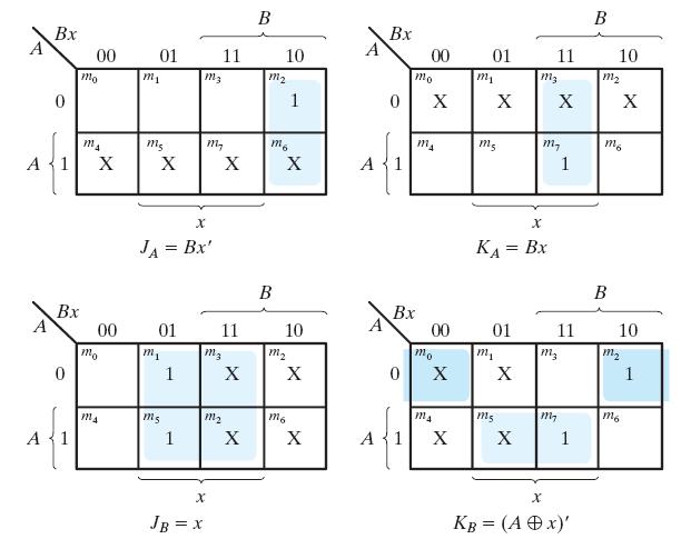
41 Example Circuit has no outputs. No need for output column FF input eq.s J A =B, K A =Bx J B =x, K B =A x+ax
42 State Table of Example
43 2 nd method (using state equations) The next state values can also be obtained by evaluating the state equations: 1. Determine the ff input equations. 2. Substitute the input equations into ff characteristic equations to obtain the state equations. 3. Use the corresponding state equations to determine the next state values.
44 Using state equations 1. Determine ff equations J A =B, K A =Bx J B =x, K B =A x+ax 2. Substitude them into ff characteristic eq.s: A(t+1)=JA +K A=BA +(Bx ) A=A B+AB +Ax B(t+1)=JB +K B= x' B' ( A x)' B B' x' ABx A' Bx' 3. Using state equations, obtain next state values.
45 From state equations to state table A(t+1)=A B+AB +Ax B(t+1)=B x +ABx+A Bx
46 Obtain state diagram State diagram
47 Analysis with T Flip-Flops Same procedure as explained for JK ffs Either use Characteristic table or Characteristic equations Characteristic equations for T ffs Q( t 1) T Q TQ T Q
48 Input eq.s, output eq. T A =Bx T B =x y=ab Substitute them into characteristic eq.s A(t+1)=(Bx) A+(Bx)A =AB +Ax +A Bx B(t+1)=x B+xB =x(xor)b Example
49 Example A(t+1)=AB +Ax +A Bx B(t+1)=x B+xB =x(xor)b y=ab Obtain state table
50 Obtain state diagram State diagram
51
52
53
54
55
56
57
58
59
60
61
62
63
64 Excitation Tables When we use D ff, state equations is found directly from the next state. We cannot do this for JK and T ffs We need function table for these ffs The table that lists the required ff inputs for the transitions from present state to next state is called excitation table. Values for the present state and next state is given. What values should be applied to flip-flop inputs?

65 Excitation Table for JK and T
66 Synthesis Using JK Flip-Flops Apply the same procedure as we did for D flipflops Except that the input equations should be evaluated by using excitation tables.
67 Example
68 Draw the circuit
69 Synthesis Using T Flip-Flops Design a 3-bit binary counter At each clock transition, the value of the state will be increased by one 000, 001, 010, ,000,.. Draw the state diagram

70 Create the state table Binary counter
71 FF Input Functions

72 Counter circuit
73 FSM State Reduction
74
75
76
77
78
79
80
81
82
83 Questions - 1 (Q.5.5) A sequential circuit with two D flip-flops A and B, two inputs x and y, and one output z is specified by the following next state and output equations A(t+1)=x y+xb B(t+1)=x A+xB Z=A a) Draw the logic diagram of the circuit. b) List the state table for the sequential circuit. c) Draw the corresponding state diagram.
84 Questions - 2 (Q.5.6) Derive the state table and the state diagram of the sequential circuit shown below. Explain the function that the circuit performs.
85 Questions - 3 (Q.5.12) Design a sequential circuit with two D flip-flops A and B and one input x_in. a) When x_in=0, the state of the circuit remains the same. When x_in=1, the circuit goes through the state transitions from 00 to 01, to 11, to 10, back to 00, and repeats. b) When x_in=0, the state of the circuit remains the same. When x_in=1, the circuit goes through the state transitions from 00 to 11, to 01, to 10, back to 00, and repeats.
86 Questions - 4 (Q.5.14) Design a sequential circuit with two JK flip-flops A and B and two inputs E and F. If E=0, the circuit remains in the same state regardless of the value of F. When E=1 and F=1, the circuit goes through the state transitions from 00 to 01, to 10, to 11, back to 00, and repeats. When E=1 and F=0, the circuit goes through the state transitions from 00 to 11, to 10, to 01, back to 00, and repeats. (Up and down counter with enable. Count up when F=1, count down when F=0.)
87 Questions - 5 (Q.5.15) A sequential circuit has three flip-flops A,B,and C; one input x_in; and one output y_out. The state diagram is shown at right. The circuit is to be designed by treating the unused states as don t-care conditions. Analyze the circuit obtained from the design to determine the effect of the unused states. Use D flip-lops in the design. Use JK flip-flops in the design.
Synchronous Sequential Logic
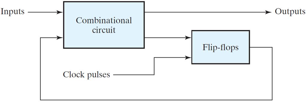
 1 IT 201 DIGITAL SYSTEMS DESIGN MODULE4 NOTES Synchronous Sequential Logic Sequential Circuits - A sequential circuit consists of a combinational circuit and a feedback through the storage elements in
Chapter 5 Synchronous Sequential Logic
 Chapter 5 Synchronous Sequential Logic Sequential circuit: A circuit that includes memory elements. In this case the output depends not only on the current input but also on the past inputs. Memory A synchronous
6 Synchronous State Machine Design
 Design of synchronous counters. Based on the description of the problem, determine the required number n of the FFs - the smallest value of n is such that the number of states N 2 n and the desired counting
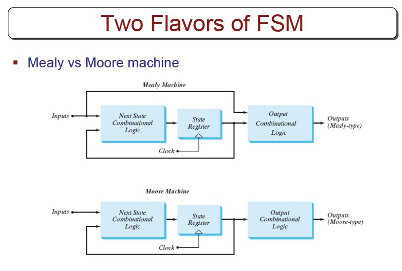
Finite State Machine. By : Ali Mustafa
 Finite State Machine By : Ali Mustafa So Far We have covered the memory elements issue and we are ready to implement the sequential circuits. We need to know how to Deal(analyze) with a sequential circuit?
Lecture (08) Synchronous Sequential Logic
 Synchronous Sequential Logic") Lecture (08) Synchronous Sequential Logic By: Dr. Ahmed ElShafee ١ Dr. Ahmed ElShafee, ACU : Spring 2018, CSE303 Logic design II Analysis of Clocked Sequential Circuits The behavior of a clocked sequential
Lecture (08) Synchronous Sequential Logic By: Dr. Ahmed ElShafee ١ Dr. Ahmed ElShafee, ACU : Spring 2018, CSE303 Logic design II Analysis of Clocked Sequential Circuits The behavior of a clocked sequential
COE 202: Digital Logic Design Sequential Circuits Part 3. Dr. Ahmad Almulhem ahmadsm AT kfupm Phone: Office:
 COE 202: Digital Logic Design Sequential Circuits Part 3 Dr. Ahmad Almulhem Email: ahmadsm AT kfupm Phone: 860-7554 Office: 22-324 Objectives Important Design Concepts State Reduction and Assignment Design
COE 202: Digital Logic Design Sequential Circuits Part 3. Dr. Ahmad Almulhem ahmadsm AT kfupm Phone: Office:
 COE 202: Digital Logic Design Sequential Circuits Part 3 Dr. Ahmad Almulhem Email: ahmadsm AT kfupm Phone: 860-7554 Office: 22-324 Objectives State Reduction and Assignment Design of Synchronous Sequential
The Design Procedure. Output Equation Determination - Derive output equations from the state table
 The Design Procedure Specification Formulation - Obtain a state diagram or state table State Assignment - Assign binary codes to the states Flip-Flop Input Equation Determination - Select flipflop types
Sequential Circuit Analysis
 Sequential Circuit Analysis Last time we started talking about latches and flip-flops, which are basic one-bit memory units. Today we ll talk about sequential circuit analysis and design. First, we ll
ELCT201: DIGITAL LOGIC DESIGN
 ELCT201: DIGITAL LOGIC DESIGN Dr. Eng. Haitham Omran, haitham.omran@guc.edu.eg Dr. Eng. Wassim Alexan, wassim.joseph@guc.edu.eg Following the slides of Dr. Ahmed H. Madian Lecture 10 محرم 1439 ه Winter
Week-5. Sequential Circuit Design. Acknowledgement: Most of the following slides are adapted from Prof. Kale's slides at UIUC, USA.
 Week-5 Sequential Circuit Design Acknowledgement: Most of the following slides are adapted from Prof. Kale's slides at UIUC, USA. Storing a value: SR = 00 What if S = 0 and R = 0? The equations on the
COEN 312 DIGITAL SYSTEMS DESIGN - LECTURE NOTES Concordia University
 1 OEN 312 DIGIAL SYSEMS DESIGN - LEURE NOES oncordia University hapter 6: Registers and ounters NOE: For more examples and detailed description of the material in the lecture notes, please refer to the
FSM model for sequential circuits
 1 FSM model for sequential circuits The mathematical model of a sequential circuit is called finite-state machine. FSM is fully characterized by: S Finite set of states ( state ~ contents of FFs) I Finite
Digital Logic and Design (Course Code: EE222) Lecture 19: Sequential Circuits Contd..
 Lecture 19: Sequential Circuits Contd..") Indian Institute of Technology Jodhpur, Year 2017-2018 Digital Logic and Design (Course Code: EE222) Lecture 19: Sequential Circuits Contd.. Course Instructor: Shree Prakash Tiwari Email: sptiwari@iitj.ac.in
Indian Institute of Technology Jodhpur, Year 2017-2018 Digital Logic and Design (Course Code: EE222) Lecture 19: Sequential Circuits Contd.. Course Instructor: Shree Prakash Tiwari Email: sptiwari@iitj.ac.in
Sequential Circuit Design
 Sequential Circuit esign esign Procedure. Specification 2. Formulation Obtain a state diagram or state table 3. State Assignment Assign binary codes to the states 4. Flip-Flop Input Equation etermination
Counters. We ll look at different kinds of counters and discuss how to build them
 Counters We ll look at different kinds of counters and discuss how to build them These are not only examples of sequential analysis and design, but also real devices used in larger circuits 1 Introducing
Different encodings generate different circuits
 FSM State Encoding Different encodings generate different circuits no easy way to find best encoding with fewest logic gates or shortest propagation delay. Binary encoding: K states need log 2 K bits i.e.,
Analysis of Clocked Sequential Circuits
 Objectives Analysis of Clocked Sequential Circuits The objectives of this lesson are as follows: Analysis of clocked sequential circuits with an example State Reduction with an example State assignment
Sequential Logic. Rab Nawaz Khan Jadoon DCS. Lecturer COMSATS Lahore Pakistan. Department of Computer Science
 Sequential Logic Rab Nawaz Khan Jadoon DCS COMSATS Institute of Information Technology Lecturer COMSATS Lahore Pakistan Digital Logic and Computer Design Sequential Logic Combinational circuits with memory
Analysis and Design of Sequential Circuits: Examples
 COSC3410 Analysis and Design of Sequential Circuits: Examples J. C. Huang Department of Computer Science University of Houston Sequential machine slide 1 inputs combinational circuit outputs memory elements
Introduction EE 224: INTRODUCTION TO DIGITAL CIRCUITS & COMPUTER DESIGN. Lecture 6: Sequential Logic 3 Registers & Counters 5/9/2010
 EE 224: INTROUCTION TO IGITAL CIRCUITS & COMPUTER ESIGN Lecture 6: Sequential Logic 3 Registers & Counters 05/10/2010 Avinash Kodi, kodi@ohio.edu Introduction 2 A Flip-Flop stores one bit of information
10/12/2016. An FSM with No Inputs Moves from State to State. ECE 120: Introduction to Computing. Eventually, the States Form a Loop
 University of Illinois at Urbana-Champaign Dept. of Electrical and Computer Engineering An FSM with No Inputs Moves from State to State What happens if an FSM has no inputs? ECE 120: Introduction to Computing
ELE2120 Digital Circuits and Systems. Tutorial Note 9
 ELE2120 Digital Circuits and Systems Tutorial Note 9 Outline 1. Exercise(1) Sequential Circuit Analysis 2. Exercise (2) Sequential Circuit Analysis 3. Exercise (3) Sequential Circuit Analysis 4. Ref. Construction
Digital Logic Design - Chapter 5
 Digital Logic Design - Chapter 5 S. Design a 2-bit binary up counter a) using positive-edge-triggered D flip-flops. b) using positive-edge-triggered T flip-flops. c) using positive-edge-triggered JK flip-flops.
CS221: Digital Design. Dr. A. Sahu. Indian Institute of Technology Guwahati
 CS221: Digital Design Counter&Registers Dr. A. Sahu DeptofComp.Sc.&Engg. Indian Institute of Technology Guwahati Outline Counter : Synchronous Vs Asynchronous Counter: Finite it State t Machine Mhi A register
3. Complete the following table of equivalent values. Use binary numbers with a sign bit and 7 bits for the value
 EGC22 Digital Logic Fundamental Additional Practice Problems. Complete the following table of equivalent values. Binary. Octal 35.77 33.23.875 29.99 27 9 64 Hexadecimal B.3 D.FD B.4C 2. Calculate the following
Sequential Synchronous Circuit Analysis
 Sequential Synchronous Circuit Analysis General Model Current State at time (t) is stored in an array of flip-flops. Next State at time (t+1) is a Boolean function of State and Inputs. Outputs at time
Chapter 7. Synchronous Sequential Networks. Excitation for
 Chapter 7 Excitation for Synchronous Sequential Networks J. C. Huang, 2004 igital Logic esign 1 Structure of a clocked synchronous sequential network Mealy model of a clocked synchronous sequential network
Lecture 17: Designing Sequential Systems Using Flip Flops
 EE210: Switching Systems Lecture 17: Designing Sequential Systems Using Flip Flops Prof. YingLi Tian April 11, 2019 Department of Electrical Engineering The City College of New York The City University
CprE 281: Digital Logic
 CprE 281: Digital Logic Instructor: Alexander Stoytchev http://www.ece.iastate.edu/~alexs/classes/ Synchronous Sequential Circuits Basic Design Steps CprE 281: Digital Logic Iowa State University, Ames,
Digital Circuits and Systems
 EE201: Digital Circuits and Systems 4 Sequential Circuits page 1 of 11 EE201: Digital Circuits and Systems Section 4 Sequential Circuits 4.1 Overview of Sequential Circuits: Definition The circuit whose
MAHALAKSHMI ENGINEERING COLLEGE TIRUCHIRAPALLI
 DEPARTMENT: ECE MAHALAKSHMI ENGINEERING COLLEGE TIRUCHIRAPALLI 6 QUESTION BANK SUBJECT NAME: DIGITAL ELECTRONICS UNIT : Design of Sequential Circuits PART A ( Marks). Draw the logic diagram 4: Multiplexer.(AUC
Chapter 4. Sequential Logic Circuits
 Chapter 4 Sequential Logic Circuits 1 2 Chapter 4 4 1 The defining characteristic of a combinational circuit is that its output depends only on the current inputs applied to the circuit. The output of
Sequential Circuits Sequential circuits combinational circuits state gate delay
 Sequential Circuits Sequential circuits are those with memory, also called feedback. In this, they differ from combinational circuits, which have no memory. The stable output of a combinational circuit
Chapter 7 Sequential Logic
 Chapter 7 Sequential Logic SKEE2263 Digital Systems Mun im/ismahani/izam {munim@utm.my,e-izam@utm.my,ismahani@fke.utm.my} March 28, 2016 Table of Contents 1 Intro 2 Bistable Circuits 3 FF Characteristics
Synchronous Sequential Logic Part I
 Synchronous Sequential Logic Part I Mantıksal Tasarım BBM23 section instructor: Ufuk Çelikcan Sequential Logic Digital circuits we have learned, so far, have been combinational no memory, outputs are entirely
11.1 As mentioned in Experiment 10, sequential logic circuits are a type of logic circuit where the output of
 EE 2449 Experiment 11 Jack Levine and Nancy Warter-Perez CALIFORNIA STATE UNIVERSITY LOS ANGELES Department of Electrical and Computer Engineering EE-2449 Digital Logic Lab EXPERIMENT 11 SEQUENTIAL CIRCUITS
Sequential Logic Circuits
 Chapter 4 Sequential Logic Circuits 4 1 The defining characteristic of a combinational circuit is that its output depends only on the current inputs applied to the circuit. The output of a sequential circuit,
ELE2120 Digital Circuits and Systems. Tutorial Note 10
 ELE2120 Digital Circuits and Systems Tutorial Note 10 Outline 1. 1. Sequential Circuit Design 2. 2. Design procedure: a complete example illustration Sequential circuit analysis & design In sequential
CHW 261: Logic Design
 CHW 26: Logic Design Instructors: Prof. Hala Zayed Dr. Ahmed Shalaby http://www.bu.edu.eg/staff/halazayed4 http://bu.edu.eg/staff/ahmedshalaby4# Slide Digital Fundamentals CHAPTER 8 Counters Slide 2 Counting
Chapter 6. Synchronous Sequential Circuits
 Chapter 6 Synchronous Sequential Circuits In a combinational circuit, the values of the outputs are determined solely by the present values of its inputs. In a sequential circuit, the values of the outputs
King Fahd University of Petroleum and Minerals College of Computer Science and Engineering Computer Engineering Department
 King Fahd University of Petroleum and Minerals College of Computer Science and Engineering Computer Engineering Department Page 1 of 13 COE 202: Digital Logic Design (3-0-3) Term 112 (Spring 2012) Final
King Fahd University of Petroleum and Minerals College of Computer Science and Engineering Computer Engineering Department
 King Fahd University of Petroleum and Minerals College of Computer Science and Engineering Computer Engineering Department Page of COE 22: Digital Logic Design (3--3) Term (Fall 22) Final Exam Sunday January
ECE/Comp Sci 352 Digital Systems Fundamentals. Charles R. Kime Section 2 Fall Logic and Computer Design Fundamentals
 University of Wisconsin - Madison ECE/Comp Sci 352 Digital Systems Fundamentals Charles R. Kime Section 2 Fall 2001 Lecture 5 Registers & Counters Part 2 Charles Kime Counters Counters are sequential circuits
Synchronous Sequential Logic Part I. BME208 Logic Circuits Yalçın İŞLER
 Synchronous Sequential Logic Part I BME28 Logic Circuits Yalçın İŞLER islerya@yahoo.com http://me.islerya.com Sequential Logic Digital circuits we have learned, so far, have been combinational no memory,
Chapter 14 Sequential logic, Latches and Flip-Flops
 Chapter 14 Sequential logic, Latches and Flip-Flops Flops Lesson 4 JK Flip Flop Ch14L4-"Digital Principles and Design", Raj Kamal, Pearson Education, 2006 2 JK Flip-Flop ve edge triggered Output Q and
Digital Logic Design - Chapter 4
 Digital Logic Design - Chapter 4 1. Analyze the latch circuit shown below by obtaining timing diagram for the circuit; include propagation delays. Y This circuit has two external input and one feedback
UNIVERSITY OF BOLTON SCHOOL OF ENGINEERING BENG (HONS) ELECTRICAL & ELECTRONICS ENGINEERING EXAMINATION SEMESTER /2017
 ELECTRICAL & ELECTRONICS ENGINEERING EXAMINATION SEMESTER /2017") UNIVERSITY OF BOLTON TW35 SCHOOL OF ENGINEERING BENG (HONS) ELECTRICAL & ELECTRONICS ENGINEERING EXAMINATION SEMESTER 2-2016/2017 INTERMEDIATE DIGITAL ELECTRONICS AND COMMUNICATIONS MODULE NO: EEE5002
UNIVERSITY OF BOLTON TW35 SCHOOL OF ENGINEERING BENG (HONS) ELECTRICAL & ELECTRONICS ENGINEERING EXAMINATION SEMESTER 2-2016/2017 INTERMEDIATE DIGITAL ELECTRONICS AND COMMUNICATIONS MODULE NO: EEE5002
Vidyalankar S.E. Sem. III [ETRX] Digital Circuits and Design Prelim Question Paper Solution
![Vidyalankar S.E. Sem. III [ETRX] Digital Circuits and Design Prelim Question Paper Solution](/thumbs/79/79145081.jpg "Vidyalankar S.E. Sem. III [ETRX] Digital Circuits and Design Prelim Question Paper Solution") S.E. Sem. III [ETRX] Digital Circuits and Design Prelim uestion Paper Solution. (a) Static Hazard Static hazards have two cases: static and static. static- hazard exists when the output variable should
S.E. Sem. III [ETRX] Digital Circuits and Design Prelim uestion Paper Solution. (a) Static Hazard Static hazards have two cases: static and static. static- hazard exists when the output variable should
Computers also need devices capable of Storing data and information Performing mathematical operations on such data
 Sequential Machines Introduction Logic devices examined so far Combinational Output function of input only Output valid as long as input true Change input change output Computers also need devices capable
DE58/DC58 LOGIC DESIGN DEC 2014
 Q.2 a. In a base-5 number system, 3 digit representations is used. Find out (i) Number of distinct quantities that can be represented.(ii) Representation of highest decimal number in base-5. Since, r=5
EE 209 Spiral 1 Exam Solutions Name:
 EE 29 Spiral Exam Solutions Name:.) Answer the following questions as True or False a.) A 4-to- multiplexer requires at least 4 select lines: true / false b.) An 8-to- mux and no other logic can be used
Gates and Flip-Flops
 Gates and Flip-Flops Chris Kervick (11355511) With Evan Sheridan and Tom Power December 2012 On a scale of 1 to 10, how likely is it that this question is using binary?...4? What s a 4? Abstract The operation
Sequential vs. Combinational
 Sequential Circuits Sequential vs. Combinational Combinational Logic: Output depends only on current input TV channel selector (-9) inputs system outputs Sequential Logic: Output depends not only on current
EE40 Lec 15. Logic Synthesis and Sequential Logic Circuits
 EE40 Lec 15 Logic Synthesis and Sequential Logic Circuits Prof. Nathan Cheung 10/20/2009 Reading: Hambley Chapters 7.4-7.6 Karnaugh Maps: Read following before reading textbook http://www.facstaff.bucknell.edu/mastascu/elessonshtml/logic/logic3.html
COE 202: Digital Logic Design Sequential Circuits Part 4. Dr. Ahmad Almulhem ahmadsm AT kfupm Phone: Office:
 COE 202: Digital Logic Design Sequential Circuits Part 4 Dr. Ahmad Almulhem Email: ahmadsm AT kfupm Phone: 860-7554 Office: 22-324 Objectives Registers Counters Registers 0 1 n-1 A register is a group
Sequential logic and design
 Principles Of Digital Design Sequential logic and design Analysis State-based (Moore) Input-based (Mealy) FSM definition Synthesis State minimization Encoding Optimization and timing Copyright 20-20by
Experiment 9 Sequential Circuits
 Introduction to Counters Experiment 9 Sequential Circuits The aim of this experiment is to familiarize you, frst with the basic sequential circuit device called a fip fop, and then, with the design and
Roger L. Tokheim. Chapter 8 Counters Glencoe/McGraw-Hill
 Digital Electronics Principles & Applications Sixth Edition Roger L. Tokheim Chapter 8 Counters 2003 Glencoe/McGraw-Hill INTRODUCTION Overview of Counters Characteristics of Counters Ripple Up Counter
課程名稱 : 數位邏輯設計 P-1/ /6/11
 課程名稱 : 數位邏輯設計 P-1/41 2012/6/11 extbook: igital esign, 4 th. Edition M. Morris Mano and Michael. iletti Prentice-Hall, Inc. 教師 : 蘇慶龍 INSRUOR : HING-LUNG SU E-mail: kevinsu@yuntech.edu.tw hapter 6 P-2/41
Sequential Logic Worksheet
 Sequential Logic Worksheet Concept Inventory: Notes: D-latch & the Dynamic Discipline D-register Timing constraints for sequential circuits Set-up and hold times for sequential circuits 6.004 Worksheet
Chapter 5 Synchronous Sequential Logic
 Chapter 5 Synchronous Sequential Logic Sequential Circuits Latches and Flip Flops Analysis of Clocked Sequential Circuits HDL Optimization Design Procedure Sequential Circuits Various definitions Combinational
EE 209 Logic Cumulative Exam Name:
 EE 209 Logic Cumulative Exam Name: 1.) Answer the following questions as True or False a.) A 4-to-1 multiplexer requires at least 4 select lines: true / false b.) An 8-to-1 mux and no other logi can be
ELEC Digital Logic Circuits Fall 2014 Sequential Circuits (Chapter 6) Finite State Machines (Ch. 7-10)
 Finite State Machines (Ch. 7-10)") ELEC 2200-002 Digital Logic Circuits Fall 2014 Sequential Circuits (Chapter 6) Finite State Machines (Ch. 7-10) Vishwani D. Agrawal James J. Danaher Professor Department of Electrical and Computer Engineering
ELEC 2200-002 Digital Logic Circuits Fall 2014 Sequential Circuits (Chapter 6) Finite State Machines (Ch. 7-10) Vishwani D. Agrawal James J. Danaher Professor Department of Electrical and Computer Engineering
ECEN 248: INTRODUCTION TO DIGITAL SYSTEMS DESIGN. Week 7 Dr. Srinivas Shakkottai Dept. of Electrical and Computer Engineering
 ECEN 248: INTRODUCTION TO DIGITAL SYSTEMS DESIGN Week 7 Dr. Srinivas Shakkottai Dept. of Electrical and Computer Engineering SEQUENTIAL CIRCUITS: LATCHES Overview Circuits require memory to store intermediate
Vidyalankar S.E. Sem. III [EXTC] Digital Electronics Prelim Question Paper Solution ABCD ABCD ABCD ABCD ABCD ABCD ABCD ABCD = B
![Vidyalankar S.E. Sem. III [EXTC] Digital Electronics Prelim Question Paper Solution ABCD ABCD ABCD ABCD ABCD ABCD ABCD ABCD = B](/thumbs/84/91058397.jpg "Vidyalankar S.E. Sem. III [EXTC] Digital Electronics Prelim Question Paper Solution ABCD ABCD ABCD ABCD ABCD ABCD ABCD ABCD = B") . (a). (b). (c) S.E. Sem. III [EXTC] igital Electronics Prelim Question Paper Solution ABC ABC ABC ABC ABC ABC ABC ABC = B LHS = ABC ABC ABC ABC ABC ABC ABC ABC But ( ) = = ABC( ) ABC( ) ABC( ) ABC( )
. (a). (b). (c) S.E. Sem. III [EXTC] igital Electronics Prelim Question Paper Solution ABC ABC ABC ABC ABC ABC ABC ABC = B LHS = ABC ABC ABC ABC ABC ABC ABC ABC But ( ) = = ABC( ) ABC( ) ABC( ) ABC( )
Time Allowed 3:00 hrs. April, pages
 IGITAL ESIGN COEN 32 Prof. r. A. J. Al-Khalili Time Allowed 3: hrs. April, 998 2 pages Answer All uestions No materials are allowed uestion a) esign a half subtractor b) esign a full subtractor c) Using
CSE370 HW6 Solutions (Winter 2010)
") SE370 HW6 Solutions (Winter 2010) 1. L2e, 6.10 For this problem we are given a blank waveform with clock and input and asked to draw out the how different flip-flops and latches would behave. LK a) b)
SE370 HW6 Solutions (Winter 2010) 1. L2e, 6.10 For this problem we are given a blank waveform with clock and input and asked to draw out the how different flip-flops and latches would behave. LK a) b)
I. Motivation & Examples
 I. Motivation & Examples Output depends on current input and past history of inputs. State embodies all the information about the past needed to predict current output based on current input. State variables,
SYNCHRONOUS SEQUENTIAL CIRCUITS
 CHAPTER SYNCHRONOUS SEUENTIAL CIRCUITS Registers an counters, two very common synchronous sequential circuits, are introuce in this chapter. Register is a igital circuit for storing information. Contents
ELCT201: DIGITAL LOGIC DESIGN
 ELCT201: DIGITAL LOGIC DESIGN Dr. Eng. Haitham Omran, haitham.omran@guc.edu.eg Dr. Eng. Wassim Alexan, wassim.joseph@guc.edu.eg Lecture 6 Following the slides of Dr. Ahmed H. Madian محرم 1439 ه Winter
Digital Electronics Sequential Logic
 /5/27 igital Electronics Sequential Logic r. I. J. Wassell Sequential Logic The logic circuits discussed previously are known as combinational, in that the output depends only on the condition of the latest
LOGIC CIRCUITS. Basic Experiment and Design of Electronics
 Basic Experiment and Design of Electronics LOGIC CIRCUITS Ho Kyung Kim, Ph.D. hokyung@pusan.ac.kr School of Mechanical Engineering Pusan National University Outline Combinational logic circuits Output
Appendix B. Review of Digital Logic. Baback Izadi Division of Engineering Programs
 Appendix B Review of Digital Logic Baback Izadi Division of Engineering Programs bai@engr.newpaltz.edu Elect. & Comp. Eng. 2 DeMorgan Symbols NAND (A.B) = A +B NOR (A+B) = A.B AND A.B = A.B = (A +B ) OR
EECS150 - Digital Design Lecture 23 - FSMs & Counters
 EECS150 - Digital Design Lecture 23 - FSMs & Counters April 8, 2010 John Wawrzynek Spring 2010 EECS150 - Lec22-counters Page 1 One-hot encoding of states. One FF per state. State Encoding Why one-hot encoding?
Exam for Physics 4051, October 31, 2008
 Exam for Physics 45, October, 8 5 points - closed book - calculators allowed - show your work Problem : (6 Points) The 4 bit shift register circuit shown in Figure has been initialized to contain the following
Written reexam with solutions for IE1204/5 Digital Design Monday 14/
 Written reexam with solutions for IE204/5 Digital Design Monday 4/3 206 4.-8. General Information Examiner: Ingo Sander. Teacher: William Sandqvist phone 08-7904487 Exam text does not have to be returned
Lecture 8: Sequential Networks and Finite State Machines
 Lecture 8: Sequential Networks and Finite State Machines CSE 140: Components and Design Techniques for Digital Systems Spring 2014 CK Cheng, Diba Mirza Dept. of Computer Science and Engineering University
Philadelphia University Student Name: Student Number:
 Philadelphia University Student Name: Student Number: Faculty of Engineering Serial Number: Final Exam, Second Semester: 2015/2016 Dept. of Computer Engineering Course Title: Logic Circuits Date: 08/06/2016
Ch 7. Finite State Machines. VII - Finite State Machines Contemporary Logic Design 1
 Ch 7. Finite State Machines VII - Finite State Machines Contemporary Logic esign 1 Finite State Machines Sequential circuits primitive sequential elements combinational logic Models for representing sequential
Lecture 14: State Tables, Diagrams, Latches, and Flip Flop
 EE210: Switching Systems Lecture 14: State Tables, Diagrams, Latches, and Flip Flop Prof. YingLi Tian Nov. 6, 2017 Department of Electrical Engineering The City College of New York The City University
Synchronous Sequential Circuit
 Synchronous Sequential Circuit The change of internal state occurs in response to the synchronized clock pulses. Data are read during the clock pulse (e.g. rising-edge triggered) It is supposed to wait
Chapter 6 Introduction to state machines
 9..7 hapter 6 Introduction to state machines Dr.-Ing. Stefan Werner Table of content hapter : Switching Algebra hapter : Logical Levels, Timing & Delays hapter 3: Karnaugh-Veitch-Maps hapter 4: ombinational
ECE 341. Lecture # 3
 ECE 341 Lecture # 3 Instructor: Zeshan Chishti zeshan@ece.pdx.edu October 7, 2013 Portland State University Lecture Topics Counters Finite State Machines Decoders Multiplexers Reference: Appendix A of
EECS150 - Digital Design Lecture 18 - Counters
 EECS150 - Digital Design Lecture 18 - Counters October 24, 2002 John Wawrzynek Fall 2002 EECS150 - Lec18-counters Page 1 Counters Special sequential circuits (FSMs) that sequence though a set outputs.
EECS150 - Digital Design Lecture 18 - Counters
 EECS50 - Digital Design Lecture 8 - Counters October 24, 2002 John Wawrzynek Fall 2002 EECS50 - Lec8-counters Page Counters Special sequential circuits (FSMs) that sequence though a set outputs. Examples:
Chapter 15 SEQUENTIAL CIRCUITS ANALYSIS, STATE- MINIMIZATION, ASSIGNMENT AND CIRCUIT IMPLEMENTATION
 Chapter 15 SEQUENTIAL CIRCUITS ANALYSIS, STATE- MINIMIZATION, ASSIGNMENT AND CIRCUIT IMPLEMENTATION Lesson 2 ANALYSIS OF CLOCKED SEQUENTIAL CIRCUIT Ch15L2- "Digital Principles and Design", Raj Kamal, Pearson
Example: vending machine
 Example: vending machine Release item after 15 cents are deposited Single coin slot for dimes, nickels o change Reset Coin Sensor Vending Machine FSM Open Release Mechanism Clock Spring 2005 CSE370 - guest
Boolean Algebra and Digital Logic 2009, University of Colombo School of Computing
 IT 204 Section 3.0 Boolean Algebra and Digital Logic Boolean Algebra 2 Logic Equations to Truth Tables X = A. B + A. B + AB A B X 0 0 0 0 3 Sum of Products The OR operation performed on the products of
Q: Examine the relationship between X and the Next state. How would you describe this circuit? A: An inverter which is synched with a clock signal.
 /2/2 OF 7 Next, let s reverse engineer a T-Flip flop Prob. (Pg 529) Note that whenever T is equal to, there is a state change, otherwise, there isn t. In this circuit, (x) determines whether the output
Design of Sequential Circuits
 Design of Sequential Circuits Seven Steps: Construct a state diagram (showing contents of flip flop and inputs with next state) Assign letter variables to each flip flop and each input and output variable
CS221: Digital Design. Indian Institute of Technology Guwahati
 CS221: Digital Design FlipFlop&Register Flop Dr. A. Sahu DeptofComp.Sc.&Engg. Indian Institute of Technology Guwahati Outline Level Sensitive (Latch) vsedge Sensitive (Flip Flop) Master Slave Flip Flop
Homework #4. CSE 140 Summer Session Instructor: Mohsen Imani. Only a subset of questions will be graded
 Homework #4 CSE 140 Summer Session 2 2017 Instructor: Mohsen Imani Only a subset of questions will be graded 1) For the circuit shown below, do the following: a. Write a logic equation for the output P
Digital Circuits ECS 371
 Digital Circuits ECS 371 Dr. Prapun Suksompong prapun@siit.tu.ac.th Lecture 18 Office Hours: BKD 3601-7 Monday 9:00-10:30, 1:30-3:30 Tuesday 10:30-11:30 1 Announcement Reading Assignment: Chapter 7: 7-1,
CDA 3200 Digital Systems. Instructor: Dr. Janusz Zalewski Developed by: Dr. Dahai Guo Spring 2012
 CDA 3200 Digital Systems Instructor: Dr. Janusz Zalewski Developed by: Dr. Dahai Guo Spring 2012 Outline Registers and Register Transfers Shift Registers Design of Binary Counters Counters for Other Sequences
Digital Design. Sequential Logic
 Principles Of igital esign Chapter 6 Sequential Logic Chapter preview Boolean algebra 3 Logic gates and flip-flops 3 Finite-state machine 6 Logic design techniques 4 Sequential design techniques 6 Binary
Chapter 4 Part 2 Sequential Circuits
 University of Wisconsin - Madison ECE/Comp Sci 352 Digital Systems Fundamentals Kewal K. Saluja and Yu Hen Hu Spring 2002 Chapter 4 Part 2 Sequential Circuits Originals by: Charles R. Kime and Tom Kamisnski
Synchronous Sequential Circuit Design
 Synchronous Sequential Circuit Design 1 Sequential circuit design In sequential circuit design, we turn some description into a working circuit We first make a state table or diagram to express the computation
CSE 140: Components and Design Techniques for Digital Systems. Lecture 9: Sequential Networks: Implementation
 CSE 4: Components and Design Techniques for Digital Systems Lecture 9: Sequential Networks: Implementation CK Cheng Dept. of Computer Science and Engineering University of California, San Diego Implementation
Digital Fundamentals
 Digital Fundamentals Tenth Edition Floyd hapter 8 Modified by Yuttapong Jiraraksopakun Floyd, Digital Fundamentals, 10 th 2008 Pearson Education ENE, KMUTT ed 2009 ounting in Binary As you know, the binary