Mitsubishi Q00/Q00UJ/Q01/QJ71
|
|
|
- Elwin Hawkins
- 6 years ago
- Views:
Transcription


1 Connection Guide Mitsubishi Q00/Q00UJ/Q01/QJ71 Supported Series: Mitsubishi Q series with QJ71C24 communication module, Q00, Q00J, Q00UJ, Q01, Q02H, Q06H, Q12H, Q25H, Q12PH, Q25PH CPU port. Website: Setting: Parameters Recommended Options Notes type Mitsubishi Q00/Q00UJ/Q01/QJ71 I/F RS485 2W/4W, Baud rate ~ Data bits 8 Parity Odd Stop bits 1 sta. no. 0 Online simulator Yes Extend address mode NO Setting: Q00, Q01 CPU port setting: 1. In GX Developer data list click [ parameter]. 2. In parameter go to [Serial] page. 3. Select [Use serial communication]. 4. Set [Transmission speed] to 9600~ Select [Sum check]. 6. Set [Transmission wait time] to 10ms. 7. Permit [RUN write setting]. 8. Click [End] to close the dialog. 9. Write the Parameter to. 10. Reset, the parameter will be actived.


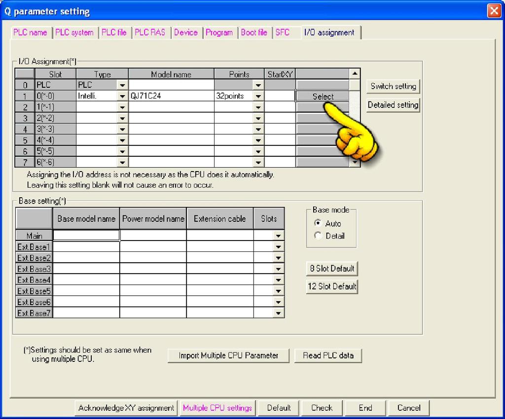
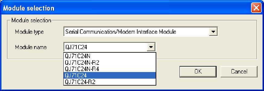
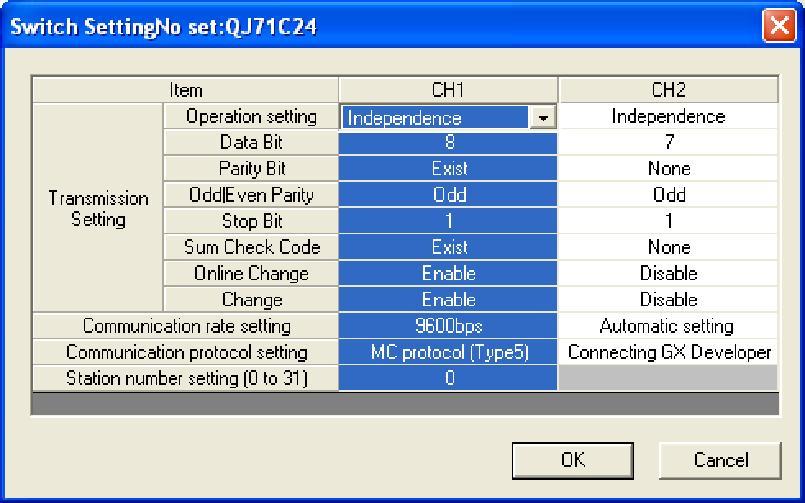
2 QJ71 setting: Connection Guide
3 Connection Guide Device Address: Bit/Word Device type Format Range Memo B X HHHH 0 ~ 1fff Input Relay B Y HHHH 0 ~ 1fff Output Relay B M DDDDD 0 ~ Internal Relay B L DDDDD 0 ~ Latch Relay B F DDDDD 0 ~ Annunciator B V DDDDD 0 ~ Edge Relay B B HHHH 0 ~ efff Link Relay B TC DDDD 0 ~ 2047 Timer Coil B SS DDDDD 0 ~ Retentive Timer Contact B SC DDDDD 0 ~ Retentive Timer Coil B CS DDDDD 0 ~ Counter Contact B CC DDDDD 0 ~ Counter Coil B SB HHH 0 ~ 7ff Special Link Relay B S DDDD 0 ~ 8191 Step Relay B DX HHHH 0 ~ 1fff Direct Input B DY HHHH 0 ~ 1fff Direct Output B TS DDDD 0 ~ 2047 Timer Contact B SM DDDD 0 ~ 2047 B D_Bit DDDDDDDh 0 ~ f B W_Bit HHHHh 0 ~ 2ffff B ZR_Bit HHHHHh 0 ~ fe7fff B ZR_Dec_Bit DDDDDDDh 0 ~ f W W HHHH 0 ~ 2fff Link Register W TN DDDD 0 ~ 2047 Timer Current Value W SN DDDD 0 ~ 2047 Retentive Timer Current Value W CN DDDD 0 ~ 1023 Counter Current Value W R FFDDDDD 0 ~ File Register (FF:File No. 0~31) (DDDDD:0~32767) W SW HHH 0 ~ 7ff Special Link Register W Z DD 0 ~ 19 Index Register W ZR HHHHH 0 ~ fe7a5 File Register W ZR_decimal_addr DDDDDDD 0 ~ W D DDDDDDD 0 ~ Data Register W SD DDDD 0 ~ 2047 W Serial_No D 0 ~ 7 W Product_No D 0 ~ 7
4 Connection Guide Wiring Diagram: QJ71C24 CH.2 RS422 Terminal (Diagram 1 ~ Diagram 4) Diagram 1 cmt3151 emt Series MT-XE emt3070/ emt3105 / emt3120 / emt3150 MT8070iE / MT6070iE / MT8100iE / MT8121iE / MT8150iE MT8121XE / MT8150XE RS485 4W 9P QJ71C24 CH.2 RS422 Terminal Rx- 1 SDB Rx+ 2 SDA Tx- 3 RDB TX+ 4 RDA GND 5 GND Diagram 2 cmt-svr COM2 RS485 4W QJ71C24 CH.2 RS422 Terminal Rx- 7 SDB Rx+ 6 SDA Tx- 9 RDB TX+ 8 RDA GND 5 GND Diagram 3
5 Connection Guide MT8071iE / MT6071iE / MT8072iE / MT6072iE / MT8073iE / MT8101iE / MT8102iE / MT8103iE MT-XE MT8090XE / MT8092XE MT6071iP / MT8071iP / MT6103iP COM2 RS485 4W 9P QJ71C24 CH.2 RS422 Terminal Rx- 1 SDB Rx+ 2 SDA Tx- 3 RDB TX+ 4 RDA GND 5 GND Diagram 4 MT8050iE MT6051iP RS485 4W QJ71C24 CH.2 RS422 Terminal Rx- 1 SDB Rx+ 2 SDA Tx- 3 RDB TX+ 4 RDA GND 5 GND
6 Connection Guide QJ71C24 CH.2 (Diagram 5 ~ Diagram 7) Diagram 5 emt Series cmt3151 emt3070/ emt3105 / emt3120 / emt3150 MT-XE MT8073iE / MT8102iE MT8092XE MT6103iP COM3 9P D-Sub Rx 2 8 TXD-3 Tx 3 7 RXD-2 GND 5 5 GND-5 DCD-1 DTR-4 DSR-6 RTS-7 CTS-8 Diagram 6 cmt-svr MT8070iE / MT6070iE / MT8100iE / MT8121iE / MT8150iE / MT8071iE / MT6071iE / MT8072iE / MT6072iE / MT8073iE / MT8101iE / MT8102iE / MT8103iE MT-XE MT8121XE / MT8150XE / MT8090XE /
7 Connection Guide 9P D-Sub Rx 2 TXD-3 Tx 3 RXD-2 GND 5 GND-5 DCD-1 DTR-4 DSR-6 RTS-7 CTS-8 Diagram 7 MT8050iE MT6051iP / MT6071iP / MT8071iP 9P D-Sub Rx 9 TXD-3 Tx 6 RXD-2 GND 5 GND-5 DCD-1 DTR-4 DSR-6 RTS-7 CTS-8
8 Connection Guide 6P Mini-DIN: Q00, Q01 CPU port (Diagram 8 ~ Diagram 10) The following is the view from the soldering point of a connector. Diagram 8 emt Series MT-XE cmt3151 emt3070/ emt3105 / emt3120 / emt3150 MT8073iE / MT8102iE MT8092XE MT6103iP COM3 6P Mini-Din Rx Tx GND 5 5 4
9 Connection Guide Diagram 9 cmt-svr MT8070iE / MT6070iE / MT8100iE / MT8121iE / MT8150iE / MT8071iE / MT6071iE / MT8072iE / MT6072iE / MT8073iE / MT8101iE / MT8102iE / MT8103iE MT-XE MT8121XE / MT8150XE / MT8090XE / 6P Mini-Din Rx 2 1 Tx 3 2 GND 5 4 Diagram 10 MT8050iE MT6051iP / MT6071iP / MT8071iP 6P Mini-Din Rx 9 1 Tx 6 2 GND 5 4
10 Connection Guide 6P Mini-DIN: Q00UJ CPU port (Diagram 11 ~ Diagram 13) The following is the view from the soldering point of a connector. Diagram 11 emt Series MT-XE cmt3151 emt3070/ emt3105 / emt3120 / emt3150 MT8073iE / MT8102iE MT8092XE MT6103iP COM3 6P Mini-DIN Rx Tx GND
11 Connection Guide Diagram 12 cmt-svr MT8070iE / MT6070iE / MT8100iE / MT8121iE / MT8150iE / MT8071iE / MT6071iE / MT8072iE / MT6072iE / MT8073iE / MT8101iE / MT8102iE / MT8103iE MT-XE MT8121XE / MT8150XE / MT8090XE / 6P Mini-DIN Rx 2 1 Tx 3 2 GND Diagram 13 MT8050iE MT6051iP / MT6071iP / MT8071iP 6P Mini-DIN Rx 9 1 Tx 6 2 GND
OP-02 / OP-03 / OP-04
 FS-i Series Check Weighing Scales Option OP-02 / OP-03 / OP-04 WM+PD4001368 Contents 1. OP-02 BATTERY... 2 1-1. Using the OP-02 SLA Battery... 2 2. OP-03 RS-232C / RELAY OUTPUT... 4 2-1. Installation...
Appendices. RS232 Commands. RS232 Connector. Pin No Specification 1 N/A 2 RXD 3 TXD 4 DTR 5 GND 6 DSR 7 RTS 8 CTS 9 N/A.
 RS232 Commands RS232 Connector 9 8 7 6 5 4 3 2 1 Pin No Specification 1 N/A 2 RXD 3 TXD 4 DTR 5 GND 6 DSR 7 RTS 8 CTS 9 N/A English 74 RS232 Protocol Function List RS232 Commands Appendices Baud Rate 9600
xlogic SuperRelay is a compact and expandable CPU replacing mini PLCs, multiple timers, relays and counters.
 SuperRelay S U P E R R E L A Y, T H E P E R F E C T A L T E R N A T I V E T O L O W C O S T P L C s A N D B A S I C R E L A Y S I N T H I S B R O C H U R E : ELC 18 Standard Models ELC 18 Economy Models
MP3 Digital Voice Module Model No.: VCM-SD Rev.A3. Content
 Content Introduction Page 01 - Feature Function / Specification Page 02 - Electronic Specification Page 03 Hardware Information - PCB Scheme Page 04 - Jumper / Connectors Description Page 04 - Operation
PTC04-DB-HALL02. Daughter Board for Melexis PTC devices. Features and Benefits. Applications. Ordering Information. Accessories. 1. Functional Diagram
 PTC0-DB-HALL0 Features and Benefits PTC0 interface board for testing devices: 0 0 0 Applications Experimental tool for Lab and Prototyping Production Equipment for Serial Programming Ordering Information
CAT Connection Cables. between. RF Amplifier ACOM 600S. and. Transceiver
 CAT Connection Cables between RF Amplifier ACOM 600S and Transceiver Document Version: v1.2 Date: January 20, 2015 Author: Nikolay Nenov Table of Contents ACOM 600S to ELECRAFT K3 RS232 CAT Connection
,- # (%& ( = 0,% % <,( #, $ <<,( > 0,% #% ( - + % ,'3-% & '% #% <,( #, $ <<,(,9 (% +('$ %(- $'$ & " ( (- +' $%(& 2,#. = '%% ($ (- +' $ '%("
 FEATURES!" #$$ % %&' % '( $ %( )$*++$ '(% $ *++$ %(%,- *(% (./ *( #'% # *( 0% ( *( % #$$ *( '( + 2' %( $ '( 2! '3 ((&!( *( 4 '3.%" / '3 3.% 7" 28" 9' 9,*: $ 9,*: $% (+'( / *(.( # ( 2(- %3 # $((% # ;' '3$-,(
POINTS OF CAUTION BEFORE USE...
 INSTRUCTION MANUAL NPN DISCRETE INPUT & NPN TRANSISTOR OUTPUT MODULE, 6 points each (-I/-II, e-con connector) MODEL BEFORE USE... Thank you for choosing M-System. Before use, check the contents of the
P300. Technical Manual I/Os, 240 solenoid drivers th Street, Davis, CA 95616, USA Tel: Fax:
 00+ I/Os, 0 solenoid drivers Technical Manual 0 th Street, Davis, CA, USA Tel: 0--00 Fax: 0--0 Email: sales@tern.com http://www.tern.com COPYRIHT, i-engine, A-Engine, R-Engine and ACTF are trademarks of
Applicable for MouseWarrior24
 AN: Migrating MWWheel and MWEyeII to the new chips Applicable for MouseWarrior. Introduction This application note is intended for those of you who have existing designs using MouseWarriorWheel or MouseWarriorEyeII.
User's Guide. DISTO online. Leica Geosystems
 User's Guide DISTO online Leica Geosystems Copyright 2001 by PMS Photo Mess Systeme AG. All rights reserved. This manual describes the versions 2.x of the program DISTO online. PMS PHOTO-MESS-SYSTEME AG
QUANTUM CONCEPT. Swimming User s Manual
 QUANTUM CONCEPT Swimming User s Manual 480.508.0 Version.4 Edition July 05 Documentation Updates Swiss Timing Ltd. reserves the right to make improvements in the products described in this documentation
RX-62N Multi-Breakout Board Options
 RX-N Multi-Breakout Board Options The RX-N Multi-Breakout Board is designed to be a low-cost prototyping tool designed for hand-assembly. Using this document and the related drawings, the board can be
Single cam type. Double cam type. Grip force N. Type Model/size Stroke Screw type straight style. Screw type tee style
 Type Model/size Stroke -SS-0-N. -SS-0-N. Single cam type -SS- 7. -SS-. -SS-4. -SD-0 Double cam type -SD- -SD-4. Screw type straight style Screw type tee style -FS- -FT- -FS- -FT- 0.9 1. 1.. 1. 4 Grip forcen
CHV Series Vector Control Inverter Options. Operating Instructions for Tension Control Card
 CHV Series Vector Control Inverter Options Operating Instructions for Control Card 1. Model and Specifications 1.1 Model The model of tension card is CHV00ZL. CHV series inverter can conduct constant
Series CCR-39S Multi-Throw DC-12 GHz, SP7T & SP8T Latching Coaxial Switch
 PART NUMBER CCR-39S DESCRIPTION Commercial Latching Multi-throw, DC-12GHz The CCR-39S is a broadband, multi-throw, electromechanical coaxial switch designed to switch a microwave signal from a common input
BEFORE USE... POINTS OF CAUTION COMPONENT IDENTIFICATION INSTRUCTION MANUAL MODEL R7K4DH-1-DAC32D R7K4DH-1-DAC32D
 INSTRUCTION MANUAL PNP DISCRETE INPUT & PNP TRANSISTOR OUTPUT MODULE, 6 points each (High-speed Link System, e-con connector) R7KDH--DACD MODEL R7KDH--DACD BEFORE USE... Thank you for choosing M-System.
PTC04-DB Daughter Board for Melexis PTC devices. Features and Benefits. Applications. Ordering Information. Accesoires. Functional Diagram
 PTC0-DB-0 Features and Benefits PTC0 interface board for testing devices 0 0 0 00 Applications Experimental tool for Lab and Prototyping Production Equipment for Serial Programming Ordering Information
Series CCR-39S Multi-Throw DC-12 GHz, SP9T & SP10T Latching Coaxial Switch
 PART NUMBER CCR-39S DESCRIPTION Commercial Latching Multi-throw, DC-12GHz The CCR-39Sis a broadband, multi-throw, electromechanical coaxial switch designed to switch a microwave signal from a common input
AN6783S. IC for long interval timer. ICs for Timer. Overview. Features. Applications. Block Diagram
 IC for long interval timer Overview The is an IC designed for a long interval timer. It is oscillated by using the external resistor and capacitor, and the oscillation frequency divided by a - stage F.F.
Series CCT-58S Multi-Throw DC 18 GHz, SP7T & SP8T Normally Open Coaxial Switch
 PART NUMBER CCT-58S DESCRIPTION Commercial Normally Open Multi-throw, DC-18 GHz The CCT-58S/CT-58S is an internally terminated, broadband, multi-throw, electromechanical coaxial switch designed to switch
MAN-SGY-012-V11 EC 5195 Fairford Electronics Ltd - Synergy Modbus RTU Programming Manual - 22nd February 2016 Page 1 of 59.
 MAN-SGY-012-V11 EC 5195 Fairford Electronics Ltd - Synergy Modbus RTU Programming Manual - 22nd February 2016 Page 1 of 59 Modbus RTU MAN-SGY-012-V11 EC 5195 Fairford Electronics Ltd - Synergy Modbus RTU
Series CCR-39S Multi-Throw DC-12 GHz, SP9T & SP10T Latching Coaxial Switch
 COAX SWITCHES Series CCR-39S PART NUMBER CCR-39S DESCRIPTION Commercial Latching Multi-throw, DC-12GHz The CCR-39Sis a broadband, multi-throw, electromechanical coaxial switch designed to switch a microwave
PTC04-DB Daughter Board for Melexis PTC devices
 PTC0-DB-0 Features and Benefits PTC0 interface board for testing devices: MLX0 MLX0 MLX0 MLX0 MLX00 MLX0 MLX0 MLX0 Applications Experimental tool for Lab and Prototyping Production Equipment for Serial
PAX2S Modbus Register Table REVISED 2/20/12 LP0894A
 PAX2S Modbus Register Table REVISED 2/2/12 LP894A REGISTER 41 42 43 44 45 46 47 48 49 41 411 412 413 414 415 416 417 418 419 42 421 422 423 424 425 426 427 428 429 43 431 432 481 482 483 484 485 486 487
Full Integration of GPS System on Arduino
 Full Integration of GPS System on Arduino Alex (Seong Hoon) Lee 1, Professor Robert Winglee 2, 1 Unviersity of Washington, Electrical Engineering Dept. 2 University of Washington, Earth and Space Sciences
DATA SHEET. Thermocouple module with digital I²C-Interface - THMOD-I²C. Characteristic features. Areas of application. Features.
 Description Characteristic features Industrial temperature measuring method Wide measuring range, -270...+1360 C Digital I²C-interface Simple integration to micro-controller Scope of supply with thermocouple,
DIN Timers TD. Options and ordering codes. Specification
 DIN imers D 17.5mm or 22.5mm DIN rail mounting Electronic imers Wide coil operation, 24V to 320V AC/DC Multi ime range / Multi function ON-Delay, OFF-Delay, Asymetrical, Star/Delta versions Perfect to
Evaluation Board for 8-/10-/12-Bit, Parallel Input, Dual-Channel, Current Output DAC EVAL-AD5428/AD5440/AD5447EB
 Evaluation Board for 8-/0-/-Bit, Parallel Input, Dual-Channel, Current Output DAC EVAL-AD58/AD50/AD5EB FEATURES Operates from dual ± V and 5 V supplies On-board reference and output amplifiers Direct hookup
Product Data Sheet KyoRack 4
 series - PANEL MOUNT PRINTERS Page 1 of 10 Introduction 5-8Vdc, 4A peak 5-8Vdc, 2A peak 10-35Vdc Features Easy open paper loading feature High resolution thermal printing 5-8Vdc standard, 10-35Vdc / low
Arithme(c logic units and memory
 Arithme(c logic units and memory CSCI 255: Introduc/on to Embedded Systems Keith Vertanen Copyright 2011 Layers of abstrac-on abstrac(on building blocks examples computer components Macbook Pro components
P300. Technical Manual
 + I/Os, solenoid drivers Technical Manual icasso venue, avis, C, US Tel: -- Fax: -- Email: sales@tern.com http://www.tern.com COYRIHT, i-engine, -Engine, R-Engine and CTF are trademarks of TERN, Inc. mes
AN10249 SC16C752/SC16C752B/ SC16C2550/SC16C2550B ISA bus hardware interface example
 INTEGRATED CIRCUITS ABSTRACT This application note shows how a SCC (or SCCB) or a SCC0 (or SCC0B) can be connected to an ISA bus. This application note is also applicable to all Philips SCC products. AN0
State Machines ELCTEC-131
 State Machines ELCTEC-131 Switch Debouncer A digital circuit that is used to remove the mechanical bounce from a switch contact. When a switch is closed, the contacts bounce from open to closed to cause
Ch 9. Sequential Logic Technologies. IX - Sequential Logic Technology Contemporary Logic Design 1
 Ch 9. Sequential Logic Technologies Technology Contemporary Logic Design Overview Basic Sequential Logic Components FSM Design with Counters FSM Design with Programmable Logic FSM Design with More Sophisticated
Product Data Sheet KyoRack 2
 series - PANEL MOUNT PRINTERS Page 1 of 10 5-8Vdc, 4A peak 5-8Vdc, 2A peak 10-35Vdc Features Easy Open paper feature High resolution thermal printing 5-8Vdc standard, 10-35Vdc / low power options Kwik
MODBUS Protocol for CS141 network card families
 Last update: 20/09/208 MODBUS Protocol for CS4 network card families Summary. MODBUS PROTOCOL... 2.. MODBUS COMMUNICATION PARAMETERS... 2.2. AVAILABLE MODBUS FUNCTION CODES... 2.3. EXCEPTION CODES... 3
SERIALLY PROGRAMMABLE CLOCK SOURCE. Features
 DATASHEET ICS307-03 Description The ICS307-03 is a dynamic, serially programmable clock source which is flexible and takes up minimal board space. Output frequencies are programmed via a 3-wire SPI port.
CBR-PB3-ATM ProBridge. User Manual
 CBR-PB3- ii Copyright Disclaimer Trademarks and patents Intended use FCC compliance Regulatory Copyright 2005, GE Security Inc. All rights reserved. This document may not be copied or otherwise reproduced,
MPP5800 series - PANEL MOUNT PRINTERS. Options
 series - PANEL MOUNT PRINTERS MPP5810 MPP5820 Introduction 5-8Vdc, 4A peak 5-8Vdc, 2A peak 10-35Vdc Features Easy load paper feature High resolution thermal printing 5-8Vdc standard, 10-35Vdc / low power
NTE74HC299 Integrated Circuit TTL High Speed CMOS, 8 Bit Universal Shift Register with 3 State Output
 NTE74HC299 Integrated Circuit TTL High Speed CMOS, 8 Bit Universal Shift Register with 3 State Output Description: The NTE74HC299 is an 8 bit shift/storage register with three state bus interface capability
Operating Instructions for Digital Manometer. Model: MAN-SD
 Operating Instructions for Digital Manometer Model: MAN-SD 1. Contents 1. Contents...2 2. Note...3 3. Instrument Inspection...3 4. Regulation Use...4 5. Operating Principle...4 6. Mechanical Connection...5
LOGIC CIRCUITS. Basic Experiment and Design of Electronics. Ho Kyung Kim, Ph.D.
 Basic Experiment and Design of Electronics LOGIC CIRCUITS Ho Kyung Kim, Ph.D. hokyung@pusan.ac.kr School of Mechanical Engineering Pusan National University Digital IC packages TTL (transistor-transistor
E2T0 DVP
 29-5-26 5116868-E2T DVP-11363-1 ENGLISH Thank you for choosing Delta s DVP series PLC. DVP4TC-E2 temperature measurement module receives 4 points of external thermocouple temperature sensors (J-type, K-type,
Clocked Sequential Circuits UNIT 13 ANALYSIS OF CLOCKED SEQUENTIAL CIRCUITS. Analysis of Clocked Sequential Circuits. Signal Tracing and Timing Charts
 ed Sequential Circuits 2 Contents nalysis by signal tracing & timing charts State tables and graphs General models for sequential circuits sequential parity checker Reading Unit 3 asic unit Unit : Latch
The Ordering Code for various standard model Recorders with an AC supply and without any additional options are as follows:
 The basic PC software is supplied free with the recorder. There is an additional charge for the extensive Data Acquisition Software supplied with communication of RS-232/422/485 or Ethernet. The Ordering
Minute Impulse Clock Controller I01DN
 99b-mi USER S MANUAL Minute Impulse Clock Controller Mon Jun 01, 2009 12:00:00 PM DST HOLD ENTER KEY TO BEGIN CANCEL HR I01DN 97 West Street Medfield, MA 02052 U.S.A. (508) 359-4396 Pg. 2 of 20 TABLE OF
" = Y(#,$) % R(r) = 1 4& % " = Y(#,$) % R(r) = Recitation Problems: Week 4. a. 5 B, b. 6. , Ne Mg + 15 P 2+ c. 23 V,
 % R(r) = 1 4& % = Y(#,$) % R(r) = Recitation Problems: Week 4. a. 5 B, b. 6. , Ne Mg + 15 P 2+ c. 23 V,") Recitation Problems: Week 4 1. Which of the following combinations of quantum numbers are allowed for an electron in a one-electron atom: n l m l m s 2 2 1! 3 1 0 -! 5 1 2! 4-1 0! 3 2 1 0 2 0 0 -! 7 2-2!
Recitation Problems: Week 4 1. Which of the following combinations of quantum numbers are allowed for an electron in a one-electron atom: n l m l m s 2 2 1! 3 1 0 -! 5 1 2! 4-1 0! 3 2 1 0 2 0 0 -! 7 2-2!
MS4525HRD (High Resolution Digital)
") MS4525HRD (High Resolution Digital) Integrated Digital Pressure Sensor (24-bit Σ ADC) Fast Conversion Down to 1 ms Low Power, 1 µa (standby < 0.15 µa) Supply Voltage: 1.8 to 3.6V Pressure Range: 1 to 150
MS4525HRD (High Resolution Digital) Integrated Digital Pressure Sensor (24-bit Σ ADC) Fast Conversion Down to 1 ms Low Power, 1 µa (standby < 0.15 µa) Supply Voltage: 1.8 to 3.6V Pressure Range: 1 to 150
ISSP User Guide CY3207ISSP. Revision C
 CY3207ISSP ISSP User Guide Revision C Cypress Semiconductor 198 Champion Court San Jose, CA 95134-1709 Phone (USA): 800.858.1810 Phone (Intnl): 408.943.2600 http://www.cypress.com Copyrights Copyrights
MEMS Capacitor Sensor Laboratory
 ROCHESTER INSTITUTE OF TEHNOLOGY MICROELECTRONIC ENGINEERING MEMS Capacitor Sensor Laboratory Dr. Lynn Fuller, Dr. Ivan Puchades Webpage: http://people.rit.edu/lffeee 82 Lomb Memorial Drive Rochester,
PI2EQX6804-ANJE EvalBoard Rev.A User Guide
 PIEQX0-ANJE EvalBoard Rev.A User Guide Introduction Pericom Semiconductor s PIEQX0-A is a low power, SAS, SATA, XAUI signal Re-Driver. The device provides programmable equalization, amplification, and
80C186EC 80C188EC AND 80L186EC 80L188EC 16-BIT HIGH-INTEGRATION EMBEDDED PROCESSORS
 80C186EC 80C188EC AND 80L186EC 80L188EC 16-BIT HIGH-INTEGRATION EMBEDDED PROCESSORS X Fully Static Operation X True CMOS Inputs and Outputs Y Y Y Integrated Feature Set Low-Power Static Enhanced 8086 CPU
244241, Operation Manual Contents subject to change without notice. Version 1.0 Issue AA
 244241, 244242 Operation Manual Contents subject to change without notice Version 1.0 Issue AA CONTENTS 1. INTRODUCTION... 2 General and Safety Information... 2 2. TECHNICAL SPECIFICATIONS... 2 3. DISPLAY
EECS150 - Digital Design Lecture 23 - FFs revisited, FIFOs, ECCs, LSFRs. Cross-coupled NOR gates
 EECS150 - Digital Design Lecture 23 - FFs revisited, FIFOs, ECCs, LSFRs April 16, 2009 John Wawrzynek Spring 2009 EECS150 - Lec24-blocks Page 1 Cross-coupled NOR gates remember, If both R=0 & S=0, then
SERVICE MANUAL. AM/FM Stereo Double Tuner
 SERVICE MANUAL TR-D000 AM/FM Stereo Double Tuner Effective : July, 00 S-00A SPECIFICATIONS NOTES PC boards shown are viewed from parts side. The parts with no reference number or no parts number in the
Program Notes Use 2:1 voltage divider on Differential Input channel 1 to get full output range from C7
 {CR10X} PROGRAM C7_datalogger_with_autogain Cyclops 7 (C7) Datalogger with Auto Gain Program example Program Notes Use 2:1 voltage divider on Differential Input channel 1 to get full output range from
Menu. Excitation Tables (Bonus Slide) EEL3701 EEL3701. Registers, RALU, Asynch, Synch
 EEL3701 EEL3701. Registers, RALU, Asynch, Synch") Menu Registers >Storage Registers >Shift Registers More LSI Components >Arithmetic-Logic Units (ALUs) > Carry-Look-Ahead Circuitry (skip this) Asynchronous versus Synchronous Look into my... 1 Excitation
Menu Registers >Storage Registers >Shift Registers More LSI Components >Arithmetic-Logic Units (ALUs) > Carry-Look-Ahead Circuitry (skip this) Asynchronous versus Synchronous Look into my... 1 Excitation
a a T = «*5S?; i; S 25* a o - 5 n s o s*- o c S «c o * * * 3 : -2 W r-< r-j r^ x w to i_q pq J ^ i_5 ft "ag i-s Coo S S o f-trj. rh.,-j,»<l,3<l) 5 s?
 5 s?") Tble f Generl rdnnce CP CB >J >> c; 5 fc5 5 S hh CD d; CC02 5^ CD Cb
Tble f Generl rdnnce CP CB >J >> c; 5 fc5 5 S hh CD d; CC02 5^ CD Cb
FATEK. FBs-1HLC. Precision Load Cell Module. Operation manual V1.1 06/07/2017 FATEK AUTOMATION CORP.
 FATEK FBs-1HLC Precision Load Cell Module Operation manual V1.1 06/07/2017 FATEK AUTOMATION CORP. 1 Contents Chapter 1 1HLC module introduction... 3 1.1 Module specification... 3 1.2 Module appearance
O P E R A T I N G M A N U A L
 OPERATING MANUAL WeatherJack OPERATING MANUAL 1-800-645-1061 The baud rate is 2400 ( 8 bits, 1 stop bit, no parity. Flow control = none) To make sure the unit is on line, send an X. the machine will respond
S-1000 Series ULTRA-SMALL PACKAGE HIGH-PRECISION VOLTAGE DETECTOR. Features. Applications. Packages. Seiko Instruments Inc. 1.
 S-1000 Series www.sii-ic.com ULTRA-SMALL PACKAGE HIGH-PRECISION VOLTAGE DETECTOR Seiko Instruments Inc., 2004-2015 Rev.3.1_00 The S-1000 series is a series of high-precision voltage detectors developed
station) on the serial port
 on the serial port") Connects a Davis VantagePro2 or Vantage Vue to a BACnet network BACnet MS/TP over RS-485 compatible Easy BACnet network configuration via onboard switches Various selectable metric and imperial unit conversions
Connects a Davis VantagePro2 or Vantage Vue to a BACnet network BACnet MS/TP over RS-485 compatible Easy BACnet network configuration via onboard switches Various selectable metric and imperial unit conversions
ELECTRICAL AND COMPUTER ENGINEERING DEPARTMENT, OAKLAND UNIVERSITY ECE-2700: Digital Logic Design Winter Notes - Unit 7 DATAPATH CIRCUIT
 Note - Unit 7 INTRODUCTION TO DIGITL SYSTM DSIGN DIGITL SYSTM MODL FSM + Datapath Circuit: DTPTH CIRCUIT Input FINIT STT MCHIN CONTROL CIRCUIT Output XMPL: CR LOT COUNTR photo receptor If = No light received
INTEGRATED CIRCUITS. For a complete data sheet, please also download:
 INTEGRATED CIRCUITS DATA SEET For a complete data sheet, please also download: The IC06 7C/CT/CU/CMOS Logic Family Specifications The IC06 7C/CT/CU/CMOS Logic Package Information The IC06 7C/CT/CU/CMOS
CS ProtoBox. Available 15 Sept 2014 at the Stores shop.
 CS ProtoBox Available Sept 0 at the Stores shop. The content of the CS Protobox is similar to the Create Protobox. The Arduino Uno, USB A B cable, DC Motor, Battery and Clip are replaced by a USB Power
MS BA01 PTH Fusion Sensor
 PRELIMINARY MS8607-02BA01 PTH Fusion Sensor Integrated pressure, temperature and humidity sensor QFN package 5 x 3 x 1 mm 3 Operating range: 10 to 2000 mbar, 0%RH to 100%RH, -40 to 85 C High-resolution
PCAN-MicroMod Evaluation Kit. Test and Development Environment for the PCAN-MicroMod. User Manual
 Test and Development Environment for the PCAN-MicroMod Products taken into account Product Name Item Number Model PCAN-MicroMod Evaluation Kit (incl. PCAN-Dongle) PCAN-MicroMod Evaluation Kit (incl. PCAN-USB)
NTE74177 Integrated Circuit TTL 35Mhz Presettable Binary Counter/Latch
 NTE74177 Integrated Circuit TTL 35Mhz Presettable Binary Counter/Latch Description: The NTE74177 is a high speed monolithic counter in a 14 Lead plastic DIP type package consisting of four DC coupled master
Theoretical Tutorial Session 2
 1 / 36 Theoretical Tutorial Session 2 Xiaoming Song Department of Mathematics Drexel University July 27, 216 Outline 2 / 36 Itô s formula Martingale representation theorem Stochastic differential equations
EEE Lecture 1 -1-
 EEE3410 - Lecture 1-1- 1. PC -> Address Move content of the Program Counter to Address Bus 2. Mem(Add) -> ID Move the Data at Location Add from main memory to Instruction Decoder (ID) 3. Acc s -> ALU Move
EECS Components and Design Techniques for Digital Systems. FSMs 9/11/2007
 EECS 150 - Components and Design Techniques for Digital Systems FSMs 9/11/2007 Sarah Bird Electrical Engineering and Computer Sciences University of California, Berkeley Slides borrowed from David Culler
MECH 1500 Final Part 2 Review
 Name: Class: Date: MECH 1500 Final Part 2 Review True/False Indicate whether the statement is true or false. 1. Programmed counters can serve the same function as mechanical counters. 2. Every PLC model
User Manual for the. Porometer. type AP4 DELTA-T DEVICES
 User Manual for the Porometer type AP4 3 DELTA-T DEVICES AP4 Porometer User Manual Version 3.1 Oct 2014 2014 Delta-T Devices Ltd Editor: Authors: Artwork: Nick Webb Tom Bragg Nick Webb Richard Spencer
Lecture 13: Sequential Circuits, FSM
 Lecture 13: Sequential Circuits, FSM Today s topics: Sequential circuits Finite state machines Reminder: midterm on Tue 2/28 will cover Chapters 1-3, App A, B if you understand all slides, assignments,
MAHALAKSHMI ENGINEERING COLLEGE TIRUCHIRAPALLI
 MAHALAKSHMI ENGINEERING COLLEGE TIRUCHIRAPALLI 6 DEPARTMENT: EEE QUESTION BANK SUBJECT NAME: DIGITAL LOGIC CIRCUITS SUBJECT CODE: EE55 SEMESTER IV UNIT : Design of Synchronous Sequential Circuits PART
Vetek Weighing AB JWL Service Manual. Service Manual. May not be reproduced in any form without written permission PAGE 0
 JWL Series Service Manual May not be reproduced in any form without written permission PAGE 0 I. Contents Assembly drawing Explosive view (JWL) List of parts (JWL) Block diagram of electronic structure
MS BA Altimeter and diving pressure sensor
 MS5803-07BA Altimeter and diving pressure sensor Excellent accuracy for both altimeter and diving applications until 70m depth Operating range: 0 to 7 bar, -20 to +85 C High resolution module, 0.4m air
NTE74176 Integrated Circuit TTL 35Mhz Presettable Decade Counter/Latch
 NTE74176 Integrated Circuit TTL 35Mhz Presettable Decade Counter/Latch Description: The NTE74176 is a high speed monolithic counter in a 14 Lead plastic DIP type package consisting of four DC coupled master
ELECTRICAL AND COMPUTER ENGINEERING DEPARTMENT, OAKLAND UNIVERSITY ECE-2700: Digital Logic Design Fall Notes - Unit 7 DATAPATH CIRCUIT
 LCTRICL ND COMPUTR NGINRING DPRTMNT, OKLND UNIVRSITY C-7: Digital Logic Deign Fall 7 Note - Unit 7 INTRODUCTION TO DIGITL SYSTM DSIGN DIGITL SYSTM MODL FSM + Datapath Circuit: DTPTH CIRCUIT Input reetn
Up/down binary counter with separate up/down clocks
 FEATURES Synchronous reversible 4-bit counting Asynchronous parallel load capability Asynchronous reset (clear) Cascadable without external logic DESCRIPTION The is a 4-bit synchronous up/down counter
Stochastic Differential Equations
 CHAPTER 1 Stochastic Differential Equations Consider a stochastic process X t satisfying dx t = bt, X t,w t dt + σt, X t,w t dw t. 1.1 Question. 1 Can we obtain the existence and uniqueness theorem for
Practice Final Exam CH 201
 Practice Final Exam CH 201 Name: (please print) Student I D : Instructions - Read Carefully 1. Please show your work, and put your final answers in the spaces provided. 2. Point values for each question
Chapter 6. Synchronous Sequential Circuits
 Chapter 6 Synchronous Sequential Circuits In a combinational circuit, the values of the outputs are determined solely by the present values of its inputs. In a sequential circuit, the values of the outputs
LE Ω SECOND SOURCE BLEED RESISTORS PART. Maxim Integrated Products 1 MAX4800A MAX4802A. TQFP 7mm x 7mm ; Rev 0; 5/08 N.C. (RGND) TOP VIEW GND
 TOP VIEW GND") 19-4120; Rev 0; 5/08 Ω Ω μ TOP VIEW DIN VDD GND (RGND) VNN 36 35 34 33 32 31 30 29 28 27 26 25 PART BED RESISTORS SECOND SOURCE PIN- PACKAGE CXZ+* No 26 CSBGA CQI+ No HV2203PJ-G 28 PLCC CCM+* No HV2203FG-G
19-4120; Rev 0; 5/08 Ω Ω μ TOP VIEW DIN VDD GND (RGND) VNN 36 35 34 33 32 31 30 29 28 27 26 25 PART BED RESISTORS SECOND SOURCE PIN- PACKAGE CXZ+* No 26 CSBGA CQI+ No HV2203PJ-G 28 PLCC CCM+* No HV2203FG-G
Leica TPS1200 GeoCOM Getting Started Manual
 Leica TPS1200 GeoCOM Getting Started Manual Version 1.0 English TPS1200 GSI to GeoCOM Conversion Table This document is meant as an introduction for users who used the GSI-online protocol in the past,
L...,,...lllM" l)-""" Si_...,...
- Si_...,...") > 1 122005 14:8 S BF 0tt n FC DRE RE FOR C YER 2004 80?8 P01/ Rc t > uc s cttm tsus H D11) Rqc(tdk ;) wm1111t 4 (d m D m jud: US
> 1 122005 14:8 S BF 0tt n FC DRE RE FOR C YER 2004 80?8 P01/ Rc t > uc s cttm tsus H D11) Rqc(tdk ;) wm1111t 4 (d m D m jud: US
AKD SYSTEM CONFIGURATION WITH KOLLMORGEN DDL LINEAR MOTORS By Kenny Hampton 1/12/2017 Rev. L
 AKD SYSTEM CONFIGURATION WITH KOLLMORGEN DDL LINEAR MOTORS By Kenny Hampton 1/12/2017 Rev. L This document shows the wiring requirements for connecting the DDL linear motors to the AKD servo drive. It
U1 PIC16C74 MCLR RA0/AN0 RA1/AN1 RA2/AN2 RA3/AN3/VREF RA4/TOCKI RA5/AN4/SS RE0/RD/AN5 9 RE1/WR/AN6 10 RE2/CS/AN
 J ICOM 0-V 0F OUT R M V ND DECODE C R0 LOCKING MN/UTO UX OUT DT TYPE J - SW V U LM R R K/% C R K % UX IN DT TYPE J R PUSH UTTON R JUMPER RadioKey mpkey DECODER DECDR_CK To: JUMPERS US RELYS OUT OUT UX
MS4525HRD (High Resolution Digital) Integrated Digital Pressure Sensor (24-bit Σ ADC) Fast Conversion Down to 1 ms Low Power, 1 µa (standby < 0.15 µa)
 Integrated Digital Pressure Sensor (24-bit Σ ADC) Fast Conversion Down to 1 ms Low Power, 1 µa (standby < 0.15 µa)") Integrated Digital Pressure Sensor (24-bit Σ ADC) Fast Conversion Down to 1 ms Low Power, 1 µa (standby < 0.15 µa) Supply Voltage: 1.8 to 3.6V Pressure Range: 1 to 150 PSI I 2 C and SPI Interface up to
Integrated Digital Pressure Sensor (24-bit Σ ADC) Fast Conversion Down to 1 ms Low Power, 1 µa (standby < 0.15 µa) Supply Voltage: 1.8 to 3.6V Pressure Range: 1 to 150 PSI I 2 C and SPI Interface up to
MS BA01. PHT Combination Sensor SPECIFICATIONS
 SPECIFICATIONS Integrated pressure, humidity and temperature sensor QFN package 5 x 3 x 1 mm 3 Operating range: 10 to 2000 mbar, 0%RH to 100%RH, -40 to 85 C High-resolution module: 0.016 mbar, 0.04%RH,
Lab 3 Revisited. Zener diodes IAP 2008 Lecture 4 1
 Lab 3 Revisited Zener diodes R C 6.091 IAP 2008 Lecture 4 1 Lab 3 Revisited +15 Voltage regulators 555 timers 270 1N758 0.1uf 5K pot V+ V- 2N2222 0.1uf V o. V CC V Vin s = 5 V Vc V c Vs 1 e t = RC Threshold
 n P! " # $ % & % & ' ( ) * + % $, $ -. $ -..! " # ) & % $/ $ - 0 1 2 3 4 5 6 7 3 8 7 9 9 : 3 ; 1 7 < 9 : 5 = > : 9? @ A B C D E F G HI J G H K D L M N O P Q R S T U V M Q P W X X Y W X X Z [ Y \ ] M
Features of Uni-Thermo
 Long-life. High reliability Uni-Thermo Peltier Device in the 1st Century CONTENTS Comparison with a Conventional Peltier Device. The Result of Operating Reliability Test Peltier Device Uni-Thermo Quality
Software BioScout-Calibrator June 2013
 SARAD GmbH BioScout -Calibrator 1 Manual Software BioScout-Calibrator June 2013 SARAD GmbH Tel.: ++49 (0)351 / 6580712 Wiesbadener Straße 10 FAX: ++49 (0)351 / 6580718 D-01159 Dresden email: support@sarad.de
* Note: If Vee varies from recommended value, you cannot get proper contrast or viewing angle.
 Example of Power Supply (Except for DMC40401 Series) Normal Temperature Type Extended Temperature Type * Note: If ee varies from recommended value, you cannot get proper contrast or viewing angle. Examples
PAST EXAM PAPER & MEMO N3 ABOUT THE QUESTION PAPERS:
 EKURHULENI TECH COLLEGE. No. 3 Mogale Square, Krugersdorp. Website: www. ekurhulenitech.co.za Email: info@ekurhulenitech.co.za TEL: 011 040 7343 CELL: 073 770 3028/060 715 4529 PAST EXAM PAPER & MEMO N3
Parity Checker Example. EECS150 - Digital Design Lecture 9 - Finite State Machines 1. Formal Design Process. Formal Design Process
 Parity Checker Example A string of bits has even parity if the number of 1 s in the string is even. Design a circuit that accepts a bit-serial stream of bits and outputs a 0 if the parity thus far is even
DS34C87T CMOS Quad TRI-STATE Differential Line Driver
 DS34C87T CMOS Quad TRI-STATE Differential Line Driver General Description The DS34C87T is a quad differential line driver designed for digital data transmission over balanced lines The DS34C87T meets all
NJU BIT PARALLEL TO SERIAL CONVERTER PRELIMINARY PACKAGE OUTLINE GENERAL DESCRIPTION PIN CONFIGURATION FEATURES BLOCK DIAGRAM
 PRELIMINARY 11-BIT PARALLEL TO SERIAL CONVERTER GENERAL DESCRIPTION The NJU3754 is an 11-bit parallel to serial converter especially applying to MCU input port expander. It can operate from 2.7V to 5.5V.