|
|
|
- Jonah Craig
- 6 years ago
- Views:
Transcription
1
2


3
4
5
6
7
8 Identification The specification of C-Lube Linear ay is identified by the identification, which consists of a model code, a size, a part code, a material code, a preload symbol, a classification symbol, interchangeable code and supplemental codes. C-Lube Linear ay type : ide type : xample of identification specification Slide unit only C C T P S /U C-Lube Linear ay M lange type, mounting from bottom : M C-Lube Linear ay M lange type, mounting from bottom : M Track rail only L R0 B P S Set product C C R0 T P S /U lange type, : MT lange type, : MT on-interchangeable specification Set product C C R0 T P /U Block type, : MS Block type, : MD Length of slide unit code umber of slide unit Compact block type, : MS Length of track rail Part code C-Lube Linear ay MUL Miniature type : MUL 0 Material Preload Accuracy class Interchangeability Optional specification Material code Preload symbol Classification symbol code Supplemental code Applicable types and size are shown in Table. to. on the next page. Mode codes for ordering track rail only are shown in Table. Table codes for ordering track rail only Material code of track rail C-Lube Linear ay type Stainless steel LLB ide type Stainless steel LLB C-Lube Linear ay M Carbon steel L Stainless steel L C-Lube Linear ay M ( to C-Lube Linear ay M ( to Carbon steel Carbon steel L LB Stainless steel Stainless steel L L ote : Applicable material and code are shown in Table on page. (o symbol (o symbol (o symbol SL (o symbol SL (o symbol SL ote : In case ordering track rail only, model code is changed as shown below. Please Reler Table. Track rail of interchangeable code LL-B (x: LLRBPS Track rail of interchangeable code LL-B (x: LLRBPS Track rail of interchangeable M code L (x: LRPS Track rail of interchangeable M code L (x: LRBPS Length of slide unit Short : C (x: CCS : o symbol igh rigidity long : G (x: MGCR xtra igh rigidity long : L (x: MTLCR = 0.0kgf = 0.lbs. = 0.0inch
9 Identification Table. Types and sizes of C-Lube Linear ay Material Shape of the slide unit Length of the slide unit code type Short igh rigidity long C G Stainless steel Short C ide type igh rigidity long G Remark : marks indicates that interchangeable products are available. 0 Applicable types and size are shown in Table. to.. umber of slide unit Length of track rail Material Set product (with track rail Slide unit only ( series Track rail only Set product (with slide unit Slide unit only Track rail only ( series Carbon steel Stainless steel : C (x : MCR : C (x : MCS : o symbol : R (x:mcr : o symbol : R (x:lrs : o symbol : SL or an assembled set, indicate the of slide units assembled on one track rail. or an interchangeable slide unit only, C shall be indicated. Indicate the length of track rail in. or standard and maximum lengths, see Track rail length in Table. to. on page to. or available model and size, see Table. to.. Table. Types and sizes of C-Lube Linear ay M Table. Types and sizes of C-Lube Linear ay M Material Shape of the slide unit Length of the slide unit code ote :, 0 and can be mounted also from bottom. ote : This can be mounted also from bottom. Remark : marks indicates that interchangeable products are available. Table. Type and sizes of C-Lube Linear ay MUL Material Shape of the slide unit Length of the slide unit code Stainless steel Miniature type MUL Remark: model is not available in MUL series. Material Carbon steel Stainless steel Stainless steel Shape of the slide unit lange type, mounting from bottom lange type, Block type, lange type, mounting from bottom lange type, Block type, igh rigidity long MSG Remark : marks indicates that interchangeable products are available. Carbon steel lange type, mounting from bottom lange type, Blocke type, Compact block type, lange type, mounting from bottom Blocke type, Compact block type, Length of the slide unit Short igh rigidity long Short igh rigidity long Short igh rigidity long Short igh rigidity long Short igh rigidity long Short igh rigidity long igh rigidity long xtra higt rigidity long igh rigidity long xtra higt rigidity long igh rigidity long Short igh rigidity long code MC M MG MTC MT MTG MSC MS MSG MC M MG MTC MT MTG MSC MS M MG MT MTG MT MD MDG MDL MS MSG MT MDC MD MDG MS 0 Table Material codes of C-Lube Linear ays Preload C-Lube Linear ay C-Lube Linear ay M C-Lube Linear ay M C-Lube Linear ay MUL Accuracy class Carbon steel (o symbol (o symbol Clearance for M Clearance for Light preload Medium preload eavy preload Ordinary class igh class Precision class Super precision class Stainless steel (o symbol SL SL (o symbol : TC : T0 : o symbol : T : T : T : o symbol : : P : SP Table Preload of C-Lube Linear ay Preload class and symbol Clearance for M Clearance for Light preload Medium preload TC T0 o symbol T T C-Lube Linear ay C-Lube Linear ay M C-Lube Linear ay M C-Lube Linear ay MUL Remark : marks are also applicable for interchangeable series. Table Accuracy of C-Lube Linear ay Accuracy class and symbol Ordinary class igh class Precision class Super precision class o symbol P SP C-Lube Linear ay C-Lube Linear ay M C-Lube Linear ay M C-Lube Linear ay MUL ote : In M series, applicable combination of the preload and accuracy is limited and shown in Table. : ot applicable to size, 0 and. Remark : marks are also applicable for interchangeable series. Specify this items for an assembled set or an interchangeable single slide unit. Applicable preload and size are shown in Table. or details of preload amount, see Table on page. or applicable accuracy, see Table. In the interchangeable specification, please combine same accuracy codes on both slide unit and track rail. or details of accuracy, see Table. to. on page to. eavy preload T ote : ot applicable to supplemental code /B (Ceramic ball specification : ot applicable to size and 0. : In M series, applicable combination of the preload and accuracy is limited and shown in Table. : Applicable to size, 0 and. : ot applicable to interchangeable specification of size, 0 and. : ot applicable to size, 0 and. Table C-Lube Linear ay M Combination of accuracy and preload Accuracy class Ordinary class igh class Precision class Preload class and symbol and symbol o symbol P Clearance for M TC o symbol Light preload T Medium preload T Remark : marks are also applicable for interchangeable series. = 0.0kgf = 0.lbs. = 0.0inch Super precision class SP
10 Identification Interchangeability : S Slide unit and track rail can be supplied separately on-interchangeable : o symbol by indicating interchangeable code S. 0 Optional specification Table. C-Lube Linear ay Applicable optional specifications Specifications Supplemental code Set product Track rail only Slide unit only Butt jointing track rail /A Opposite reference surfaces arrangement /D Specified rail mounting hole positions / Ceramic balls /B Appending inspection sheet / Black chrome surface treatment /LR ithout track rail mounting bolts /M o rubber end seals / Track rail with stopper pins /S Under seals /U Matched sets to be used as an assembled group / Table. C-Lube Linear ay M Applicable optional specifications Specifications Supplemental code Set product Track rail only Slide unit only Butt jointing track rail Opposite reference surfaces arrangement Specified rail mounting hole positions Caps for rail mounting holes Append an inspection sheet emale threads for bellows Black chrome surface treatment luoric black chrome surface treatment ith track rail mounting bolts Change of mounting hole size o rubber end seals Butt jointing interchangeable track rail Under seals Double end seals Matched sets to be used as an assembled group Scrapers Applicable special specifications are shown in Table. to.. hen a combination of several special specifications (Table. to. is required, arrange their supplemental codes in alphabetical order. or detail of special specifications, see page to. Table.. C-Lube Linear ay M Applicable optional specifications (or size, 0 and Specifications Supplemental code Set product Track rail only Slide unit only Butt jointing track rail Opposite reference surfaces arrangement Specified rail mounting hole positions Caps for rail mounting holes Append an inspection sheet Black chrome surface treatment ith track rail mounting bolts (Applicable to set order ithout track rail mounting bolts (Applicable to track rail order o rubber end seals Under seals Matched sets to be used as an assembled group /A /D / / / /J /L /L /MA /M / /T /U /V / /Z /A /D / / / /L /MA /M / /U / ote : Applicable to size,, and. : ot applicable to size and 0. : ot applicable to size,, 0 and. Remark : marks indicates that interchangeable products are available. ote : ot applicable to interchangeable specification of stainless steel model. : Applicable to size. : ot applicable to on interchangeable specification. Remark : marks indicates that interchangeable products are available. ote : Applicable to size of carbon steel product. : Applicable to size. : Applicable to only track rail. (Supplemental code LR Remark : marks indicate that interchangeable products are available. Table.. C-Lube Linear ay M Applicable optional specifications (or size and bigger Specifications Supplemental code Set product Track rail only Slide unit only Butt jointing track rail Opposite reference surfaces arrangement Specified rail mounting hole positions Caps for rail mounting holes Append an inspection sheet emale threads for bellows Black chrome surface treatment luoric black chrome surface treatment ith track rail mounting bolts (Applicable to set order ithout track rail mounting bolts (Applicable to track rail order o rubber end seals Rail cover plate Butt jointing interchangeable track rail Double end seals Matched sets to be used as an assembled group Scrapers Specified rail mounting hole positions Black chrome surface treatment ith track rail mounting bolts Upper seals Matched sets to be used as an assembled group Table. Table. Specifications /A /D / / / /J /L /L /MA /M / /PS /T /V / /Z Supplemental code / /LR C-Lube Linear ay Combination of optional specifications C-Lube Linear ay M Combination of optional specifications Remark : marks indicates that this combination can be made. : marks indicates that the combination is available for also interchangeable specification. Remark : marks indicates that this combination can be made. : marks indicates that the combination is available for also interchangeable specification. : Please consult when marks required. Table. C-Lube Linear ay MUL Applicable optional specifications D B LR M S U D J L L MA M PS T U V Z A A D D B LR J M L L S MA U M PS T U on-interchangeable specification V Table. D J L L MA M T U V Z A ote : ot applicable to stainless steel interchangeable specification. : Applicable to carbon steel size and bigger. : ot applicable to non interchangeable specification. Remark : marks indicate that interchangeable products are available. C-Lube Linear ay M Combination of optional specifications ote : hen a combination of /MA and /M is necessary, indicate /MA. Remark : marks indicates that this combination can be made. : marks indicates that the combination is available for also interchangeable specification. : Please consult when marks required. Table. D J L L MA M C-Lube Linear ay MUL Combination of optional specifications LR MA U LR MA U Remark : marks indicates that this combination can be made. T = 0.0kgf = 0.lbs. = 0.0inch U V
11 Load Ratings and Life Basic dynamic load rating C Conforming to ISO/DIS - The basic dynamic load rating is defined as a constant load both in direction and magnitude under which a group of identical C-Lube Linear ays are individually operated and 0% of those in the group can travel 00 m free from material damage due to rolling contact fatigue. Basic static load rating C 0 Conforming to ISO/DIS - The basic static load rating is defined as a static load that gives a prescribed constant contact stress at the center of the contact area between rolling elements and raceways receiving the maximum load. Life The rating life of C-Lube Linear ay series is obtained from the following calculation formula. L C = 0( P where, L : Rating life, 0 m C : Basic dynamic load rating, P : quivalent load, If the stroke length and the or strokes per minute are known, the life in hours must be corrected by the following formula. L 0 L h = Sn where, L h : Rating life in hours, hours S : Stroke length, : umber of strokes per minute, cpm n ig. Static moment rating direction Static moment rating,, Static safety factor The static safety factor f S of C-Lube Linear ay series is given in the following formula, and general values of this factor are shown in Table. f C 0 S = P 0 where, f S : Static safety factor C 0 : Basic static load rating, : Static load, P 0 Table Static safety factor Operating conditions C, C 0 ig. Load direction The static moment rating is defined as a static moment load (See ig. that gives a prescribed constant contact stress at the center of the contact area between rolling elements and raceways receiving the maximum load. The static moment rating is used in combination with the static safety factor to give the limiting load for normal rolling motion. Operation with vibration and/or shocks igh operating performance ormal operation Load factor f S Actual loads applied to the linear motion rolling guide sometimes exceed the theoretically calculated load due to vibration and shocks caused by machine operation. The actual life is calculated from the following formula while considering the load factor. Table 0 Load factor Condition Smooth operation free from vibration and/or shocks ormal operation Operation with shock loads f.... Dynamic equivalent load hen there is any load in the direction other than basic dynamic load rating or combined load, dynamic equivalent load is obtained for life calculation. rom each directional load, converted load equal to downward or lateral is given by following formulae. where, re : Converted downward load, ae : Converted lateral load, r : Downward load, a : Lateral load, M 0 : moment, m M X : moment, m M Y : moment, m k r,k a : Conversion factor by load direction (See Table C 0 : Basic static load rating, : static moment, m : static moment, m : static moment, m C 0 re = k r r + M 0 + M X C 0 C 0 ae = k a a + T M Y Y Table Conversion factor by load direction C-Lube Linear ay C-Lube Linear ay M C-Lube Linear ay M C-Lube Linear ay MUL r a Conversion factor k r r 0 r 0.. k a..... rom the converted downward and lateral load, mean equivalent dynamic load must be corrected by the following formula. P= X re +Y ae where, P : Mean equivalent dynamic load, X,Y : Mean equivalent dynamic load factor (See Table re : Converted downward load, : Converted lateral load, ae Table Mean equivalent dynamic load factor Condition X re ae re ae 0. Static equivalent load hen there is any load in the direction other than basic dynamic load rating or combined load, mean equivalent static load is obtained for static safety factor calculation. rom each directional load, converted load equal to downward or lateral is given by following formula. where, P 0 : Static equivalent load, r : Downward load, a : Lateral load, M 0 : moment, M X : moment, M Y : moment, k 0r,k 0a : Conversion factor by load direction (See Table C 0 : Basic static load rating, : static moment, : static moment, : static moment, C 0 P 0 = k 0r r + k 0a a + M 0 + M X + M Y Table Conversion factor by load direction C-Lube Linear ay C-Lube Linear ay M C-Lube Linear ay M C-Lube Linear ay MUL C 0 C 0 r Conversion factor k 0r r 0 r 0 a.. = 0.0kgf = 0.lbs. = 0.0inch Y 0. k 0a.....
12 Accuracy Preload Accuracy of the assembled set of C-Lube Linear ay are shown in Table. to.. Table. Accuracy of C-Lube Linear ay Item Dim. Tolerance Dim. Tolerance Dim. variation of Dim. variation of Dim. variation of for multiple sets Parallelism in operation of Parallelism in operation of ote : : Remark : Parallelism m 0 C A D Classification (Symbol C to A D to B B igh Refer to ig.. Refer to ig.. igh ( Precision (P Precision P unit : 0.0 Dimensional variation of dimension means the size variation between the slide units mounted on the same track rail when the dimension is measured at the same measuring position of track rail. Applicable for series. Aiso applicable to size to of C-Lube Linear ay M. Table. Accuracy of C-Lube Linear ay M and M Classification (Symbol Ordinary igh Item o symbol Dim. Tolerance Dim. Tolerance Dim. variation of Dim. variation of Dim. variation of for multiple sets Parallelism in operation of Parallelism in operation of ote : : Remark : Parallelism m 0 C A D C to A D to B B 0.0 Ordinary (no symbol 0.0 and igh Precision P Refer to ig.. Refer to ig.. ( Precision (P Super precision (SP unit : Super precision SP Dimensional variation of dimension means the size variation between the slide units mounted on the same track rail when the dimension is measured at the same measuring position of track rail. Applicable for series. or size to of C-Lube Linear ay M, see Table.. Table. Accuracy of C-Lube Linear ay MUL Item Dim. Tolerance Dim. Tolerance Dim. variation of Dim. variation of Parallelism in operation of C to A Parallelism in operation of Parallelism m Classification (Symbol 0 C A D D to B Ordinary Refer to ig.. igh Average amount of preload for C-Lube Linear ay series is shown in Table. In case, high rigidity and/or damping are needed, the preload amount is recoended to be / of the external force. owever, excessive preload will cause short life. Table Preload amount Item Symbol Preload class Clearance preloado symbol Light preload TC T0 T Preload amount C 0 o symbol Medium preload.0 C eavy preload.0 C ote : Approx. 0m clearance : Zero or minimal amount of clearance Zero or minimal amount of preload Refer to ig.. : Remark : C 0 means basic static load rating. Ordinary (no symbol and igh ( unit : ote : Dimensional variation of dimension means the size variation between the slide units mounted on the same track rail when the dimension is measured at the same measuring position of track rail. B e Y axis Typical application Smooth motion To absorb slight misalignment Smooth motion Smooth and precise motion Minimum vibration Load is equally balanced. Smooth and precise motion Medium vibration Medium overhung load Vibration and/or shocks Large overhung load eavy cutting Geometrical moment of inertia igh rigidity design of C-Lube Linear ay MUL is achieved by adopting a U-shaped track rail. Table shows the moment of inertia of sectional area of track rails. Table C-Lube Linear ay MUL Moment of inertia of sectional area of track rails X axis ig.. Length of track rail L C-Lube Linear ay Parallelism in operation ig.. Length of track rail L C-Lube Linear ay M and M Parallelism in operation 0 0 ig Length of track rail L C-Lube Linear ay MUL Parallelism in operation MU MUL Moment of inertia of sectional area I X.0.0 I Y Center of gravity e = 0.0kgf = 0.lbs. = 0.0inch
13 Optional special specifications for use under special environment C-Lube Linear ay series with the special specifications shown in Table. to. are optionally available for various applications. hen ordering, add any supplemental codes onto the identification. If a combination of special specifications is required, indicate the supplemental codes in alphabetical order. These optional items can be combined to achieve further improvements in performance. Butt jointing track rails -A -B -A -B -A -B -A -B Opposite reference surfaces arrangement Reference mounting surface of track rail Reference mounting surface of track rail /A /D The reference mounting surface of track rail is made opposite to the standard side. The accuracy of dimension including parallelism in operation is the same with that of standard specification. Specified track rail mounting hole positions mark / The mounting hole positions of track rail can be specified by specifying dimension at the left end, which is the distance from the mounting hole nearest to the left end of the track rail to the left end face of the track rail in sight of mark on the slide unit. hen ordering, add the dimension (in after /. Dimension can be specified in a limited range. Consult for further information. If long dimension is required, imperfect mounting hole may remain. ith caps for rail mounting holes (for M and M series / Specify prepared caps for track rail mounting holes are appended. These caps cover the track rail mounting holes to improve the sealing performance in the linear motion direction. Aluminum caps are also available. Consult for further information. Ceramic ball specification Table C /B G C G /B /B /B /B /B C /B /B G /B C /B /B G /B C C Caps (Made of synthetic resin hen the required length of non-interchangeable track rail exceeds the maximum length shown in page to, two or (for series /B more track rails can be used by butt jointing them in the direction of linear motion. or the length and the of butt jointing track rails, please consult. Steel balls in the slide unit are changed to ceramic (silicon nitride material. Load ratings and static moment ratings are shown in Table. Load ratings and static moment ratings of ceramic ball specification C-Lube Linear ay m m m ote : The upper values in the and column apply to one slide unit, and the lower values apply to two slide units in close contact. ith inspection sheet The inspection sheet recording dimensions and (See Accuracy, dimensional variations of and, and parallelism in operation of the slide unit is attached to each set. ith female threads for bellows (for M and M series /J /JR /JL emale threads for bellows ith female threads for bellows emale threads for bellows emale threads for mounting bellows are provided on the interchangeable slide unit or the interchangeable track rail of C-Lube Linear ay M and M series. or details of related dimensions, see Table. and.. q /J emale threads are provided at both ends of the slide unit or the track rail. w /JR emale threads are provided at the right end of the slide unit in sight of mark. e /JL emale threads are provided at the left end of the slide unit in sight of mark. (for assembled set of M and M series /J /JJ /JR /JS /JJS emale threads for bellows emale threads for bellows or an assembled set of interchangeable or non-interchangeable specification, female threads for mounting bellows are provided on the slide unit and the track rail. or the details of related dimensions, see Table. and.. q /J emale threads are provided at both ends of the track rail, and at the slide unit ends which are the closest to the track rail ends. (In case only one slide unit is assembled, female threads are provided at both ends. w /JJ emale threads are provided at both ends of the track rail, and at all ends of all slide units. (Applicable, when the of slide units is two or more. In case only one slide unit is assembled, indicate /J. e /JR emale threads are provided at both ends of the track rail. r /JS emale threads are provided at the slide unit ends which are the closest to the track rail ends. (In case only one slide unit is assembled, female threads are provided at both ends. t /JJS emale threads are provided at all ends of all slide units. (Applicable, when the of slide units is two or more. In case only one slide unit is assembled, indicate /JS. = 0.0kgf = 0.lbs. = 0.0inch Slide unit Track rail Table. C-Lube Linear ay M Dimension of female threads for bellows a a a a D D b b B b b Block Type unit : Slide unit Track rail M a a b b b b M L a a depth depth MTC MT MTG MSC M. M MS MSG MTC MT.. MTG MSC MS MSG MTC MT MTG MSC MS MSG MTC MT MTG MSC MS MSG MTC MT MSC MS MT MS b b.. a a M B depth lange Type b b M depth M depth M depth Grease nipple AM. 0 a a M M 0 M M M ote : The specification and mounting position of grease nipple are different from those of the standard specification product. models are provided with a special specification grease nipple (PB type. or details of dimension, consult for further information. : The values are for the slide unit with female threads for bellows at both ends. Remark : The table shows representative model s but is also applicable to stainless steel models. L M M M M M0
14 Optional special specifications for use under special environment Table. C-Lube Linear ay M Dimension of female threads for bellows a a D b b b b b a a M B depth lange Type b M depth M depth Grease nipple AM b b L M depth Black chrome surface treatment /LC /LR /LCR A black permeable chrome film is formed to improve corrosion resistance. q /LC Treatment is applied to the casing. w /LR Treatment is applied to the track rail. e /LCR Treatment is applied to the casing and the track rail. or detail of applicability, see Table. to. on page to. o end seal (for, M and M series / nd pressure plate nd pressure plate Track rail with stopper pins (for non-interchangeable series /S Stopper pin Stopper pin b b b b a a D MT MD MS MT MTG MS MSG MT MTG MD MDG MS MSG MT MTG MTL MD MDG MDL MS MSG MT MTG MT MD MDG MD MT MTG MTL MD MDG MDL ote : The specification and the mounting position of grease nipple are different from those of the standard specification product. models are provided with a special specification grease nipple (PB type. or details of dimension, consult for further information. : The values are for the slide unit with female threads for bellows at both ends. Remark : The table shows representative model s but is also applicable to stainless steel models. B M depth a a a a Block Type Compact Block Type unit : Slide unit Track rail a a b b b b M M L a a depth depth... M 0. M... 0 M. M 0. 0 M. M M M 0 M M 0 M M0 D B a a M depth luorine black chrome surface treatment (for M and M series ith track rail mounting bolts (for M, MUL and set order of M /LC /LR /LCR After forming a black permeable chrome film, the surface is coated with fluorine resin for further improvement in corrosion resistance. This treatment is also effective in preventing the adhesion of foreign substances on the surface. q /LC Treatment is applied to the body of slide unit. w /LR Treatment is applied to the track rail. e /LCR Treatment is applied to the body of slide unit and the track rail. or detail of applicability, see Table. to. on page to. Change of mounting hole size and female threads size (for M and MSL /MA Track rail mounting bolts are appended according to the of mounting holes. ithout track rail mounting bolts (for and interchangeable track rail order of M Track rail mounting bolts are not appended. /M /M The track rail mounting holes for M of M is changed to M. If with track rail mounting bolts is also required, specify /MA. nd rubber seals at both ends of slide unit are replaced by steel end pressure plates (not in contact with the track rail to reduce frictional resistance. The under seals are not assembled. This specification is not effective for dust protection. Rail cover plate for track rail (for non-interchangeable M series Rail cover plate /PS After mounting the track rail, the top surface of track rail is covered with a U-shaped thin stainless steel plate for further improvement in sealing performance. The rail cover plate is delivered as assembled on the track rail. end seals must be replaced with the special end seals. hen mounting the cover plate, refer to the attached instruction manual for rail cover plate. To prevent the slide unit of C-Lube Linear ay from slipping off of the track rail, a stopper pins are provided at both ends of the track rail. or related dimensions, see Table below. Table C-Lube Linear ay Track rail with stopper pins (Supplemental code /S b a M M c a b c Butt-jointing interchangeable track rail (for interchangeable specification of M and M series = 0.0kgf = 0.lbs. = 0.0inch unit : a b c Remark : The table shows representative model s but is also applicable to all the models in the same size of and series... /T A special interchangeable track rail of which both ends are finished for butt jointing in the direction of linear motion is provided. Use the track rails having the same interchangeable code for butt jointing. or the butt jointing for non-interchangeable specification, indicate butt-jointing track rail /A.
15 Optional special specifications for use under special environment ith under seals (for and M series Under seals are attached to M series as standard specification. /U ith upper seals (for MUL series /U D C ith double end seals (for assembled set of M and M series /V /VV Matched sets to be used as an assembled group (Applicable to non-interchangeable spec. / Set A Set B Under seal To prevent foreign substances intruding from the lower side of Linear ay, rubber seals are provided on the bottom faces of slide unit. or size, see Table. Table dimension of slide unit with under seals (Supplemental code /U M M unit : A Rubber seals are attached to the upper side face of the slide unit to prevent foreign materials from entering from the upper side, so that the mounting reference surface D cannot be used. Table shows sizes of the slide unit when upper seals are attached. Table Dimension of the slide unit with upper seals (Supplemental code /U MU MUL A.. B B unit : Remark : In case upper seals specification, the reference surface of slide unit can not be used. nd seal nd seal Spacer Double end seals are provided on the slide unit of assembled set of interchangeable specification or noninterchangeable specification for more effective dust protection. or the total length of the slide unit with double end seals, see the Table. q/v Double end seals are provided at the ends of slide units which are the closest to the ends of the track rail. (In case only one slide unit is assembled, double end seals are provided at both ends. w/vv Double end seals are provided at all ends of all slide units. (Applicable when the of slide units is two or more. In case only one slide unit is assembled, indicate /V. Table Dimension of the slide unit with double end seals (Supplemental code /VV (L (L or two or more sets of C-Lube Linear ay used on the same plane, the dimensional variation of of C-Lube Linear ay is kept within the specified range. The dimensional variation of dimension in matched sets is the same as that of a single set. Indicate the of sets after /. (x: CR/ ith scrapers (for interchangeable single slide unit of M and M series /Z /ZR /ZL Metal scrapers are provided on the slide unit of interchangeable specification. The scraper (non-contact type is used to effectively remove large particles of dust or foreign matter adhering to the track rail. or the total length of the slide unit with scrapers, see Table. q /Z Scrapers are provided at both ends of the slide unit. w /ZR A scraper is provided at the right end of the slide unit in sight of mark. e /ZL A scraper is provided at the left end of the slide unit in sight of mark. M M M M M M MT SL M SL MT ote : dimension of and MT models is the same as the dimension without under seals. Remark : The table shows representative model s but is also applicable to all the models in the same size of,, M and MT series ith double end seals (for interchangeable single slide unit of M and M series /V /VR /VL Double rubber end seals are provided on the interchangeable slide unit for more effective dust protection. or the total length of the slide unit with double end seals, see the Table. q /V Double end seals are provided at both ends of the slide unit. w /VR Double end seals are provided at the right end of the slide unit in sight of mark. e /VL Double end seals are provided at the left end of the slide unit in sight of mark. MC M MG MC M MG MC M MG MC M MG MC M M Remark : L L M M MG M MG M MG MTL M MG MT M MG MTL unit : L L The above table shows representative model s but is applicable to all models of the same size. : The values are for the slide unit with double end seals at both ends. = 0.0kgf = 0.lbs. = 0.0inch
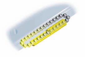
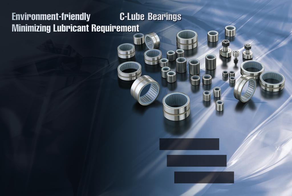
16 Optional special specifications for use under special environment Lubrication and Dust protection ith scrapers (for assembled set of M and M series Scraper Spacer nd seal /Z /ZZ Metal scrapers are provided on the slide units of assembled set of interchangeable specification or non-interchangeable specification. Scrapers (non-contact type are used to effectively remove large particles of dust or foreign matter adhering to the track rail. or the total length of the slide unit with scrapers, see Table. q /Z Scrapers are provided at the ends of slide units which are the closest to the ends of the track rail. (In case only one slide unit is assembled, scrapers are provided at both ends. w /ZZ Scrapers are provided at all ends of all slide units. (Applicable when the of slide units is two or more. In case only one slide unit is assembled, indicate /Z. Table Dimension of the slide unit with scrapers (Supplemental code /Z /ZZ Scraper (L (L Scraper unit : L L L L MC 0 M M M 0 MG MG MC M 0 M MG MG 0 0 M MC MG 0 M 0 MTL MG M MC 0 MG M 0 MT MG M 0 MC 0 MG M MTL M Remark : The above table shows representative model s but is applicable to all models of the same size. : The values are for the slide unit with scrapers at both ends. Lithium-soap base grease (MULTMP PS o. : KYODO YUSI is pre-packed in C-Lube Linear ay and lithium-soap base grease containing extreme pressure additive (ALVAIA grease P : SLL is pre-packed C-Lube Linear ay M, M and MUL. Additionally, C-Lube (Capillary sleeve a component part is placed in the ball recirculation path, thereby extending the re-lubrication (greasing interval time and maintenance work for a long period. C-Lube Linear ay is provided with an oil hole and with grease nipple shown in Table and. Supply nozzles matching the size of grease nipple are available. or these parts for lubrication, consult for further information. C-Lube Linear ay is dust protected with special rubber seals. But, if large amount of fine contaminants may present, or if large particles of foreign matter such as dust or chips may fall on the track rail, it is recoended to provide protective covers such as bellows for the entire linear motion mechanism. Bellows to match the dimensions of C-Lube Linear ay are optionally available. They are easy to mount and highly effective for dust protection. If required, consult. Table Oil hole M 0 d d Rubber part of end seal nd seal d 0. Casing nd plate Dimension of oil hole d unit : Table Grease nipple unit : Grease nipple Type Shape and dimension MT M M M M M M M M M A-M B-M A-M B-M idth across flats. M M Approx... idth across flats. R Approx.. quivalent to JIS type R idth across flats M.. idth across flats M MT SL M SL MU... MUL. Remark : The table shows representative model s but is also applicable to all the models in the same size. M M M M JIS type Approx.. quivalent to JIS type idth across flats 0 PT/.. Remark : The table shows representative model s but is also applicable to all the models in the same size. = 0.0kgf = 0.lbs. = 0.0inch
17 Precautions for use q Mounting surface, reference mounting surface, and general mounting structure To mount C-Lube linear way, correctly fit the reference mounting surfaces B and D of the slide unit and track rail to the reference mounting surfaces of the table and the bed, and then fix them tightly. (See ig.. and. The reference mounting surfaces B and D and the mounting surfaces A and C of C-Lube Linear ay are accurately finished by grinding. Stable and high accuracy liner motion can be obtained by finishing the mating mounting surfaces of machines or equipment with high accuracy and correctly mounting the guide on these surfaces. The slide unit reference mounting surface is always the side surface opposite to the mark. The track rail reference mounting surface is identified by locating the mark on the top surface of the track rail. The track rail reference mounting surface is the side surface above the mark (in the direction of the arrow. (See ig.. and. C C A D D B ig.. C-Lube Linear ay, M and M Reference mounting surfaces and general mounting structure Reference mounting surfaces D B Track rail Reference mounting surfaces mark Slide unit mark Slide unit ig.. C-Lube Linear ay, M and M Reference mounting surfaces mark Track rail ig.. C-Lube Linear ay MUL Reference mounting surfaces Reference mounting surfaces D mark w Corner radius and shoulder height of reference mounting surfaces It is recoended to make a relieved fillet at the corner of the mating reference mounting surfaces as shown in ig.. Otherwise, corner radius R and R are recoended shown in Table. and.. Table. and. shows recoended shoulder heights and radius of the reference mounting surfaces. B Table. h R M M 0 MT MS MT MS MT MS MT MS MT MS MT MS C-Lube Linear ay and M Shoulder height and radius of the reference mounting surfaces R Slide unit Shoulder height h..... Slide unit Relieved radius R max Track rail Shoulder height h unit : Track rail Relieved radius R max. ote : or with under seals of the size models, 0. is recoended. : or with under seals (supplemental code /U, it is recoended to use a value obtained by subtracting from the value h shown in the table. Remark : The table shows representative model s but is also applicable to all the models in the same size. h R.. R Table. h R C-Lube Linear ay M and MUL Shoulder height and radius of the reference mounting surfaces R Slide unit Slide unit Shoulder height h.. Relieved radius R max. Track rail Shoulder height h unit : Track rail Relieved radius R max. MT SL. MD SL 0. M SL. MD 0 SL 0. MT. MD 0. M 0. M M M M M.. MU.. 0. MUL. ote : or with under seals (supplemental code /U, it is recoended to use a value obtained by subtracting 0. from the value h shown in the table. : Provide a relieved fillet as shown ig.. Remark : The table shows representative model s but is also applicable to all the models in the same size. e Multiple slide units mounted in close distance hen using multiple slide units in close distance to each other, actual load may be greater than the calculated load depending on the mounting accuracy of the slide units on the mounting surfaces and the reference mounting surfaces of the machine. It is suggested in such cases to assume a greater load than the calculated load. r Operating temperature The C-Lube Linear ay must be used under 0 C (maximum. h R R A B ig. Relieved radius shape of reference mounting surface t Cleaning Do not wash C-Lube Linear ay with organic solvent and/or white kerosene, which have the ability of removing fat nor leave them in contact with the above agents. ig.. C-Lube Linear ay MUL Reference mounting surfaces and general mounting structure = 0.0kgf = 0.lbs. = 0.0inch
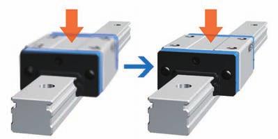
18 Mounting q Assembling two or more sets of C-Lube Linear ay specification In the case of an interchangeable specification product, assemble a slide unit and a track rail with the same interchangeable code. ( S slide unit + S track rail on-interchangeable specification Use an assembly of slide unit and track rail as delivered without changing the combination. Matched sets to be used as an assembled group Special specification products of matched sets (by supplemental code / are delivered as a group in which dimensional variations are specially controlled. Mount them without mixing with the sets of another group. w Assembling a slide unit and a track rail hen assembling C-Lube Linear ay, correctly fit the slide unit mounted on a steel ball holder to the groove of the track rail, and then move the slide unit gently from the steel ball holder to the track rail in parallel direction. Steel balls are retained in C-Lube Linear ay, so the slide unit can be separated freely from the track rail. owever, the slide unit can be assembled on the track rail much easier by using the steel ball holder. Steel ball holder is appended as an accessory to the interchangeable slide unit of C-Lube Linear ay as shown in Table. The steel ball holder for another models is also available. If required, consult for further information. Table C-Lube Linear ay and M s to which a steel ball holder is appended C-Lube Linear ay C-Lube Linear ay M C C 0 MT SL C, G C, G M SL C, G C, G MT SL G G MDC, G SL G G MDC, G0SL G G MDC, GSL G MT MD e Machining accuracy of mounting surfaces Inadequate mounting accuracy of C-Lube Linear ay will affect the operating accuracy and life adversely, so mounting must be carried out with care. hen multiple sets are mounted, the parallelism between the two mounting surfaces of machines must be prepared, in general, as shown in Table. If mounting parallelism is poor, frictional resistance will steeply increase giving a warning signal, which can be used to perform high accuracy mounting. Table Parallelism between two mounting surfaces unit : m Class Parallelism Ordinary o symbol igh Precision P Super precision SP 0 r Cleaning the mounting surfaces hen mounting C-Lube Linear ay, first clean all mounting and reference mounting surfaces. (See ig. Remove burrs and blemishes from the reference mounting surfaces and mounting surfaces of the machine using an oil-stone, etc., and then wipe the surfaces with clean cloth. Remove rust preventive oil and dirt from the reference mounting surfaces and mounting surfaces with clean cloth. ig. Cleaning the mounting surfaces t Plugging-in of caps for rail mounting holes hen plugging the caps for rail mounting holes (supplemental code / into the mounting holes of track rail, tap in the cap gently by applying a flat plate on the top face of the cap until the top face of the cap becomes level with the top face of the track rail. Table. C-Lube Linear ay (standard type and maximum lengths of track rails lat plate ig. Plugging-in of caps for rail mounting holes y Tightening torque of mounting bolts The standard torque values for C-Lube Linear ay mounting bolts are shown in Table. and.. hen machines or equipment are subjected to serve vibration, shock, large fluctuating load, or moment load, the bolts should be tightened with a torque. to. times higher than the standard torque values shown. hen the mating member material is cast iron or aluminum, tightening torque should be lowered in accordance with the strength characteristics of the material. Table. Tightening torque m Bolt size Carbon steel bolt Stainless steel bolt Strength division. Property division A-0 M 0... M M M.. M..0. M0.. M. 0 Remark : or C-Lube Linear ay, M (size, 0 and and MUL, see Table.. Track rail lengths Item C-Lube Linear ay M and M Tightening torque of mounting bolts and maximum lengths of track rails are shown in Table. to.. Track rail in any length are also available. Simply indicate the necessary length of track rail in millimeter ( in the identification. or the tolerance of dimention and Track rail length, consult for further information. length Ln Mounting hole pitch Reference Over (Incl. dimension Under L n (umber of mounting holes M M Table. C-Lube Linear ay, M (size, 0 and and MUL Tightening torque of mounting bolts Bolt size M 0. M.. M.0. M.. M 0. M 0. M 0. M Tightening torque m Carbon steel bolt Stainless steel bolt Strength division. Property division A In non-interchangeable specification, for track rail longer than the maximum length shown in Table. to., butt-jointing track rails are available upon request. In this case, indicate supplemental code /A in the identification. dimensions at both ends are the same unless otherwise specified. To change these dimensions, specify the specified rail mounting hole positions (supplemental code / of special specification unit : Maximum length Maximum of track rails for butt jointing Maximum length of butt jointing track rails 0 0 ote : ot applied to optional specification track rail stopper pins (supplemental code /S. : The track rails can be manufactured up to the maximum length shown in parentheses. If required, please consult for further information. : ot applicable to interchangeable specification. Remark : The table shows representative model s but is also applicable to all the models in the same size. = 0.0kgf = 0.lbs. = 0.0inch
19 Track rail lengths Table. C-Lube Linear ay (wide type and maximum lengths of track rails Table. C-Lube Linear ay M and maximum lengths of track rails n (umber of mounting holes n (umber of mounting holes n (umber of mounting holes Item Table. length Ln Mounting hole pitch Reference Over (Incl. dimension Under Maximum length Maximum of track rails for butt jointing Maximum length of butt jointing track rails L ote : ot applied to optional specification track rail stopper pins (supplemental code /S. : The track rails can be manufactured up to the maximum length shown in parentheses. If required, please consult : ot applicable to interchangeable specification. Remark : The table shows representative model s but is also applicable to all the models in the same size. Item C-Lube Linear ay M and maximum lengths of track rails length Ln Mounting hole pitch Reference Over (Incl. dimension Under Maximum length n (umber of mounting holes L M M M M ote : hen specifying a butt-jointing interchangeable track rail (supplimental code /T, pay attention to the dimension at the butt-jointing part. : ot applicable to the track rail with female threads for bellows (Supplemental code /J. : The dimension of stainless steel product is the half value of dimension. : The track rails can be manufactured up to the maximum length shown in parentheses. If required, please consult for further information. Remark : The table shows representative model s but is also applicable to all the models in the same size. unit : unit : M 000 M MSL MSL MSL MSL for further information Item ote : ot applicable to the track rail with female threads for bellows (Supplemental code /J : The track rails can be manufactured up to the maximum length shown in parentheses. If required, please consult Remark : The table shows representative model s but is also applicable to all the models in the same size. Table. length Ln Mounting hole pitch Reference Over (Incl. dimension Under Maximum length Item length Ln Mounting hole pitch Reference Over (Incl. dimension Under Maximum length C-Lube Linear ay MUL and maximum lengths of track rails M M M M M M M L Item length Ln Mounting hole pitch Reference Over (Incl. dimension Under Maximum length for further information. unit : unit : M SL M0SL MSL MSL MSL MSL MSL n (umber of mounting holes L unit : MU MUL ote : The track rails can be supplied with up to the length shown in parentheses as maximum. If required, please consult for further information. = 0.0kgf = 0.lbs. = 0.0inch
20 C-Lube Linear ay type CG Oil hole -M depth (L (L (L (L -M depth d C C M G G C C G G h C, L C C G C G C G C G C G C G Mass (Reference g Slide unit Track rail (per Dimension of assembly L L M depth Dimension of slide unit ote : Track rail lengths L are shown in Table.. : The directions of basic dynamic load rating (C, basic static load rating (C 0 and static moment rating (, and are shown in the sketches below. The upper values in the and column apply to one slide unit, and the lower values apply to two units in close contact. Remark : The appended bolts for mounting track rails are hexagon socket head bolts of JIS B or equivalent, or cross-recessed head cap screws for precision equipment. : Oil hole is provided for (C to (C, G models C, C 0 T M. M. M M. M M M d h. 0 Dimension of track rail type Length of slide unit C Short o symbol G igh rigidity long.. 0. code G,,,,,, umber of slide unit (two slide units Length of track rail ( Appended mounting bolt for track rail Bolt size length Cross-recessed head screw for precision equipment M exagon socket head bolt M exagon socket head bolt M exagon socket head bolt M exagon socket head bolt M0 exagon socket head bolt M exagon socket head bolt M xample of identification for assembled set Part code C R Basic Basic dynamic static load rating load rating C Preload symbol C Class symbol Static moment rating m m code m T P S /U code S specification on interchangeable o symbol specification Preload amount T0 Clearance o symbol T Light preload C C G C G C G C G C G C G Supplemental code Special specification A, D,, B,, LR, M,, S, U, P Accuracy class igh Precision In case ordering track rail only, model code is changed as shown below. Track rail of interchangeable code LL-B (x: LLRBPS = 0.0kgf = 0.lbs. = 0.0inch
21 C-Lube Linear ay ide type CG -M depth (L (L (L (L -M depth Oil hole d C0C 0 GG C G C G h C, 0 L C 0 0 C G C G C G C G C G Mass (Reference g Slide unit Track rail (per Dimension of assembly Dimension of slide unit L L M depth d h ote : Track rail lengths L are shown in Table.. : The directions of basic dynamic load rating (C, basic static load rating (C 0 and static moment rating (, and are shown in the sketches below. The upper values in the and column apply to one slide unit, and the lower values apply to two units in close contact. Remark : The appended bolts for mounting track rails are hexagon socket head bolts of JIS B or equivalent, or cross-recessed head cap screws for precision equipment. : Oil hole is provided for (C, G0 to (C, G models C, C 0 T M.. M M M M M Dimension of track rail xample of identification for assembled set 0 code ide type Length of slide unit C Short o symbol G igh rigidity long 0,,,,, umber of slide unit (two slide units Length of track rail ( G Bolt size length Cross-recessed head screw for precision equipment M. Appended mounting bolt for track rail exagon socket head bolt M exagon socket head bolt M exagon socket head bolt M exagon socket head bolt M exagon socket head bolt M Part code C R Basic Basic dynamic static load rating load rating C Preload symbol C Class symbol Static moment rating m m code S m Supplemental code T P /U code S specification on interchangeable o symbol specification Preload amount T0 Clearance o symbol T Light preload C 0 0 C G C G C G C G C G Special specification A, D,,, LR, M,, S, U, P Accuracy class igh Precision In case ordering track rail only, model code is changed as shown below. Track rail of interchangeable code LL-B (x: LLRBPS = 0.0kgf = 0.lbs. = 0.0inch
22 C-Lube Linear ay M lange type, mounting from bottom Short MC M igh rigidity longmg d (L (L -d (L (L -d h MC(SL L MC MC M M MG MG MC MC M M MG MG MC MC M M MG MG SL SL SL SL SL SL SL SL SL Mass (Reference Slide unit kg Track rail kg/m...0 Dimension of Dimension of slide unit Dimension of track rail Recoended Basic Basic Static moment rating assembly mounting bolt dynamic static for track rail load rating load rating C C 0 L L d d h Bolt size length m m m. ote : Track rail lengths L are shown in Table.. : Track rail mounting bolts are not appended. exagon socket bolts of JIS B strength division. or equivalent are recoended. Values in parentheses are applicable to the track rail of supplemental code /M of special specification. : The directions of basic dynamic load rating (C, basic static load rating (C 0 and static moment rating (, and are shown in the sketches below. The upper values in the and column apply to one slide unit, and the lower values apply to two units in close contact. Remark : Values in parentheses are applicable to the track rail of supplemental code "/M" of special specification (.. (.. (. M (M M M xample of identification for assembled set,, code M G umber of slide unit (two slide units Length of track rail ( Part code C R Material o symbol igh carbon steel SL Stainless steel Preload amount Tc Clearance o symbol T Light preload T Medium preload o symbol P SP MC MC M M MG MG MC MC M M MG MG MC MC M M MG MG T P S /U Accuracy class SL SL SL SL SL SL SL SL SL Material code Preload symbol Class symbol code Supplemental code code C, C M lange type, 0 S T0 T mounting from bottom specification X o on interchangeable Length of slide unit symbol specification C Short o symbol G igh rigidity long Special specification A, D,,,, J, L, L, MA, M,, T, U, V,, Z Ordinary igh Precision Super precision In case ordering track rail only, model code is changed as shown below. Track rail of interchangeable M code L (x: LRPS = 0.0kgf = 0.lbs. = 0.0inch
23 C-Lube Linear ay M lange type, mounting from bottom Short MC M igh rigidity longmg d (L (L -d (L (L -d h MC(SL L MC MC SL Mass (Reference Slide unit kg 0. Track rail kg/m Dimension of Dimension of slide unit Dimension of track rail Recoended Basic Basic Static moment rating assembly mounting bolt dynamic static for track rail load rating load rating C C 0 L L d d h Bolt size length m m m 0 00 MC MC SL M M SL M 00 0 M M SL MG MG SL MG MG SL MC M M MC M M M M ote : Track rail lengths L are shown in Table.. : Track rail mounting bolts are not appended. exagon socket bolts of JIS B strength division. or equivalent are recoended. : The directions of basic dynamic load rating (C, basic static load rating (C 0 and static moment rating (, and are shown in the sketches below. The upper values in the and column apply to one slide unit, and the lower values apply to two units in close contact. C, C 0 T0 xample of identification for assembled set code M G Part code C R Material code Preload symbol Class symbol code Supplemental code T P S /U lange type, M mounting from bottom Length of slide unit C Short o symbol G igh rigidity long,, umber of slide unit (two slide units Length of track rail ( Material o symbol igh carbon steel SL Stainless steel code S specification o on interchangeable symbol specification Preload amount Tc Clearance o symbol T Light preload T Medium preload Special specification A, D,,,, J, L, L, MA,, T, U, V,, Z o symbol P SP Accuracy class Ordinary igh Precision Super precision In case ordering track rail only, model code is changed as shown below. Track rail of interchangeable M code L (x: LRPS = 0.0kgf = 0.lbs. = 0.0inch
24 C-Lube Linear ay M lange type, Short MTC MT igh rigidity longmtg d (L (L -M (L (L -M h MTC(SL L MTC MTC SL MT MT SL MTG MTG SL MTC MTC SL MT MT SL MTG MTG SL MTC MTC SL MT MT SL MTG MTG SL Mass (Reference Slide unit kg Track rail kg/m...0 Dimension of Dimension of slide unit Dimension of track rail Recoended Basic Basic Static moment rating assembly mounting bolt dynamic static for track rail load rating load rating C C 0 L L M d h Bolt size length m m m. ote : Track rail lengths L are shown in Table.. : Track rail mounting bolts are not appended. exagon socket bolts of JIS B strength division. or equivalent are recoended. Values in parentheses are applicable to the track rail of supplemental code /M of special specification. : The directions of basic dynamic load rating (C, basic static load rating (C 0 and static moment rating (, and are shown in the sketches below. The upper values in the and column apply to one slide unit, and the lower values apply to two units in close contact. Remark : Values in parentheses are applicable to the track rail of supplemental code "/M" of special specification M M M (.. (.. (. M (M M M xample of identification for assembled set code MT G Part code C R MTC MTC SL MT MT SL MTG MTG SL MTC MTC SL MT MT SL MTG MTG SL MTC MTC SL MT MT SL MTG MTG SL Material code Preload symbol Class symbol code Supplemental code T P S /U C, C 0 T0 lange type, MT Length of slide unit C Short o symbol G igh rigidity long,, umber of slide unit (two slide units Length of track rail ( Material o symbol igh carbon steel SL Stainless steel code S specification o on interchangeable symbol specification Preload amount Tc Clearance o symbol T Light preload T Medium preload Special specification A, D,,,, J, L, L, MA, M,, T, U, V,, Z o symbol P SP Accuracy class Ordinary igh Precision Super precision In case ordering track rail only, model code is changed as shown below. Track rail of interchangeable M code L (x: LRPS = 0.0kgf = 0.lbs. = 0.0inch
25 C-Lube Linear ay M lange type, Short MTC MT igh rigidity longmtg d (L (L -M (L (L -M h MTC(SL L MTC MTC SL Mass (Reference Slide unit kg 0. Track rail kg/m Dimension of Dimension of slide unit Dimension of track rail Recoended Basic Basic Static moment rating assembly mounting bolt dynamic static for track rail load rating load rating C C 0 L L M d h Bolt size length m m m 0 00 MTC MTC SL MT MT SL M0 0 0 M 00 0 MT MT SL MTG MTG SL MTG MTG SL MTC MT M0 0 0 M MTC MT MT M.. 0 M MT ote : Track rail lengths L are shown in Table.. : Track rail mounting bolts are not appended. exagon socket bolts of JIS B strength division. or equivalent are recoended. : The directions of basic dynamic load rating (C, basic static load rating (C 0 and static moment rating (, and are shown in the sketches below. The upper values in the and column apply to one slide unit, and the lower values apply to two units in close contact. C, C 0 T0 xample of identification for assembled set code MT G Part code C R Material code Preload symbol Class symbol code Supplemental code T P S /U lange type, MT Length of slide unit C Short o symbol G igh rigidity long,, umber of slide unit (two slide units Length of track rail ( Material o symbol igh carbon steel SL Stainless steel code S specification o on interchangeable symbol specification Preload amount Tc Clearance o symbol T Light preload T Medium preload Special specification A, D,,,, J, L, L, MA,, T, U, V,, Z o symbol P SP Accuracy class Ordinary igh Precision Super precision In case ordering track rail only, model code is changed as shown below. Track rail of interchangeable M code L (x: LRPS = 0.0kgf = 0.lbs. = 0.0inch
26 C-Lube Linear ay M Block type, Short MSC MS igh rigidity longmsg (L (L -M depth (L (L -M depth d h MSC(SL L MSC MSC SL Mass (Reference Slide unit kg 0.0 Track rail kg/m Dimension of Dimension of slide unit Dimension of track rail Recoended Basic Basic Static moment rating assembly mounting bolt dynamic static for track rail load rating load rating C C 0 L L M depth d h Bolt size length m m m.... MSC MSC SL MS MS SL M... (.. (. ( M (M 0... MS MS SL MSG MSG SL MSG MSG SL MSC MSC SL MSC MSC SL MS MS SL M... M MS MS SL MSG MSG SL MSG MSG SL MSC MSC SL MSC MSC SL MS MS SL M. M MS MS SL MSG MSG SL MSG MSG SL ote : Track rail lengths L are shown in Table.. : Track rail mounting bolts are not appended. exagon socket bolts of JIS B strength division. or equivalent are recoended. Values in parentheses are applicable to the track rail of supplemental code /M of special specification. : The directions of basic dynamic load rating (C, basic static load rating (C 0 and static moment rating (, and are shown in the sketches below. The upper values in the and column apply to one slide unit, and the lower values apply to two units in close contact. Remark : Values in parentheses are applicable to the track rail of supplemental code "/M" of special specification. xample of identification for assembled set code MS G Part code C R Material code Preload symbol Class symbol code Supplemental code T P S /U C, C 0 T0 Block type, MS Length of slide unit C Short o symbol G igh rigidity long,, umber of slide unit (two slide units Length of track rail ( Material o symbol igh carbon steel SL Stainless steel code S specification o on interchangeable symbol specification Preload amount Tc Clearance o symbol T Light preload T Medium preload Special specification A, D,,,, J, L, L, MA, M,, T, U, V,, Z o symbol P SP Accuracy class Ordinary igh Precision Super precision In case ordering track rail only, model code is changed as shown below. Track rail of interchangeable M code L (x: LRPS = 0.0kgf = 0.lbs. = 0.0inch 0
27 C-Lube Linear ay M Block type, Short MSC MS igh rigidity longmsg (L (L -M depth (L (L -M depth d h MSC(SL L MSC MSC SL Mass (Reference Slide unit kg 0. Track rail kg/m Dimension of Dimension of slide unit Dimension of track rail Recoended Basic Basic Static moment rating assembly mounting bolt dynamic static for track rail load rating load rating C C 0 L L M depth d h Bolt size length m m m 0 00 MSC MSC SL MS MS SL M 0 M 00 0 MS MS SL MSG MSG SL MSG MSG SL MSC MS M 0 0 M MSC MS MS.0... M0.. 0 M MS ote : Track rail lengths L are shown in Table.. : Track rail mounting bolts are not appended. exagon socket bolts of JIS B strength division. or equivalent are recoended. : The directions of basic dynamic load rating (C, basic static load rating (C 0 and static moment rating (, and are shown in the sketches below. The upper values in the and column apply to one slide unit, and the lower values apply to two units in close contact. C, C 0 T0 xample of identification for assembled set code MS G Part code C R Material code Preload symbol Class symbol code Supplemental code T P S /U Block type, MS Length of slide unit C Short o symbol G igh rigidity long,, umber of slide unit (two slide units Length of track rail ( Material o symbol igh carbon steel SL Stainless steel code S specification o on interchangeable symbol specification Preload amount Tc Clearance o symbol T Light preload T Medium preload Special specification A, D,,,, J, L, L, MA,, T, U, V,, Z o symbol P SP Accuracy class Ordinary igh Precision Super precision In case ordering track rail only, model code is changed as shown below. Track rail of interchangeable M code L (x: LRPS = 0.0kgf = 0.lbs. = 0.0inch
28 C-Lube Linear ay M lange type, mounting from bottom M igh rigidity longmg (L (L -d d h L M Mass (Reference Slide unit kg 0. Track rail kg/m. Dimension of slide unit Dimension of track rail Recoended Basic Basic Static moment rating mounting bolt dynamic static for track rail load rating load rating C C 0 L L d d h Bolt size length m m Dimension of assembly M 0 0. m. M M MG M M MG M MG M M MG M MG M M MG M MG M M MG M MG M M MG ote : Track rail lengths L are shown in Table.. : Track rail mounting bolts are not appended. exagon socket bolts of JIS B strength division. or equivalent are recoended. : The directions of basic dynamic load rating (C, basic static load rating (C 0 and static moment rating (, and are shown in the sketches below. The upper values in the and column apply to one slide unit, and the lower values apply to two units in close contact. xample of identification for assembled set code M G Part code C R Material code Preload symbol Class symbol code Supplemental code T P S /D C, C 0 T0 lange type, M mounting from bottom Length of slide unit o symbol G igh rigidity long,,,,, umber of slide unit (two slide units Length of track rail ( Material o symbol igh carbon steel SL Stainless steel code S specification o on interchangeable symbol specification Preload amount T0 Clearance o symbol T Light preload T Medium preload T eavy preload P SP Special specification A, D,,,, J, L, L, MA, M,, PS, T, V,, Z Accuracy class igh Precision Super precision In case ordering track rail only, model code is changed as shown below. Track rail of interchangeable M code L (x: LRBPS = 0.0kgf = 0.lbs. = 0.0inch
29 C-Lube Linear ay M lange type, MT igh rigidity longmtg xtra igh rigidity longmtl d d d (L (L -M h MT SL M SL MT SL L Mass Dimension of Dimension of slide unit Dimension of track rail Recoended Basic Basic Static moment rating (Reference assembly mounting bolt dynamic static for track rail load rating load rating Slide Track C C 0 unit rail L L d M d h kg kg/m Bolt size length m m m MT SL M M MT SL MSL M M MSL MT MT SL M 0... M... MT MT SL MT MT SL M.. M MT MT SL MT MT SL.. M 0... M MTG MTG MT MT SL MT 0 00 MT MT SL MT SL M 0. M MTG MTG MT 0 00 MT MT SL. 0. MT SL MTG M M0 0 MTG MTL MTL MT MT MTG M M MTG MT MT MT MT MTG M M MTG MTL MTL ote : Track rail lengths L are shown in Table.. : Track rail mounting bolts are not appended. exagon socket bolts of JIS B strength division. or equivalent are recoended. : The directions of basic dynamic load rating (C, basic static load rating (C 0 and static moment rating (, and are shown in the sketches below. The upper values in the and column apply to one slide unit, and the lower values apply to two units in close contact. xample of identification for assembled set : MTSL, MT0SL, MT MTSL, MTL, MTL, and MTL can be mounted also from bottom direction. code Part code Material code Preload symbol Class symbol code Supplemental code Remark : Oil hole is provided for size and 0 models. MT G C R T P S /D C, C 0 T0 lange type, MT mounting from bottom Length of slide unit igh rigidity long o symbol G L code S specification o on interchangeable symbol specification Special specification A, D,,,, J, L, L, MA, M,, PS, T, V,, Z xtra igh rigidity long Accuracy class Preload amount T0 Clearance P, 0,,,,,,, o symbol SP umber of slide unit (two slide units Material T Light preload o symbol igh carbon steel T Medium preload Length of track rail ( SL Stainless steel T eavy preload igh Precision Super precision In case ordering track rail only, model code is changed as shown below. Track rail of interchangeable M code L (x: LRBPS = 0.0kgf = 0.lbs. = 0.0inch
30 C-Lube Linear ay M Block type, Short MDC MD igh rigidity longmdg xtra igh rigidity longmtl M depth M depth d MDC,G SL MDC,G0 SL MDC,G SL MD h (L (L (L (L MDCSL L Mass Dimension of Dimension of slide unit Dimension of track rail Recoended Basic Basic Static moment rating (Reference assembly mounting bolt dynamic static for track rail load rating load rating Slide Track C C 0 unit rail L L M depth d h kg kg/m Bolt size length m m m MDC SL MDC SL MD SL M M MD SL 0 MDG SL MDG SL MDC 0SL MDC 0SL MD 0SL M M MD 0SL MDG 0SL MDG 0SL MDC SL MDC SL MD MD MD SL M M.. MD SL MDG SL MDG SL MD M 0.. M MD MD MD.0... M 0. M MDG MDG MD MD MDG M 0 M 00 0 MDG MDL MDL MD MD MDG M 0 M MDG MD MD MD MD MDG M0. 0 M MDG 0 MDL MDL ote : Track rail lengths L are shown in Table.. : Track rail mounting bolts are not appended. exagon socket bolts of JIS B strength division. or equivalent are recoended. xample of identification for assembled set : The directions of basic dynamic load rating (C, basic static load rating (C 0 and static moment rating (, and are shown in the sketches below. code Part code Material code Preload symbol Class symbol code Supplemental code The upper values in the and column apply to one slide unit, and the lower values apply to two units in close contact. Remark : Oil hole is provided for size to 0 models. MD G C R T P S /D C, C 0 T0 Block type, MD Length of slide unit C Short o symbol G igh rigidity long L xtra igh rigidity long, 0,,,,,, umber of slide unit (two slide units Length of track rail ( Material o symbol igh carbon steel SL Stainless steel code S specification o on interchangeable symbol specification Preload amount T0 Clearance o symbol T Light preload T Medium preload T eavy preload P SP Special specification A, D,,,, J, L, L, MA, M,, PS, T, U, V,, Z Accuracy class igh Precision Super precision In case ordering track rail only, model code is changed as shown below. Track rail of interchangeable M code L (x: LRBPS = 0.0kgf = 0.lbs. = 0.0inch
31 C-Lube Linear ay M Compact block type, MS igh rigidity longmsg (L (L M depth d h L MS MS SL Mass (Reference Slide unit kg 0. Track rail kg/m. Dimension of Dimension of slide unit Dimension of track rail Recoended Basic Basic Static moment rating assembly mounting bolt dynamic static for track rail load rating load rating C C 0 L L M depth d h Bolt size length m m m... M.. M MS MS SL MS MS SL MSG M0... M MS MS SL MSG MS MS SL MSG M. M MS MS SL MSG MS MS MSG SL M 0 M MS MS MSG SL ote : Track rail lengths L are shown in Table.. : Track rail mounting bolts are not appended. exagon socket bolts of JIS B strength division. or equivalent are recoended. : The directions of basic dynamic load rating (C, basic static load rating (C 0 and static moment rating (, and are shown in the sketches below. The upper values in the and column apply to one slide unit, and the lower values apply to two units in close contact. C, C 0 T0 xample of identification for assembled set code MS G Part code C R Material code Preload symbol Class symbol code Supplemental code T P S /D Compact block type, MS Length of slide unit o symbol G igh rigidity long,,, umber of slide unit (two slide units Length of track rail ( Material o symbol igh carbon steel SL Stainless steel code S specification o on interchangeable symbol specification Preload amount o symbol T Light preload T Medium preload T eavy preload P SP Special specification A, D,,,, J, L, L, MA, M,, PS, T, U, V,, Z Accuracy class igh Precision Super precision In case ordering track rail only, model code is changed as shown below. Track rail of interchangeable M code L (x: LRBPS = 0.0kgf = 0.lbs. = 0.0inch
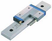
32 C-Lube Linear ay MUL Miniature type MUL -M depth Oil hole (L d h L Mass (Reference g Slide unit Track rail (per 00 Dimension of Dimension of slide unit Dimension of track rail Recoended Basic Basic Static moment rating assembly mounting bolt dynamic static for track rail load rating load rating C C 0 L M depth d h Bolt size length m m m MUL. M Cross-recessed head screw for precision equipment M MUL MUL.. M exagon socket head bolt M MUL ote : Track rail lengths L are shown in Table.. : Track rail mounting bolts are not appended. In case recoended bolts are required, please indicate /MA onto the identification. : The directions of basic dynamic load rating (C, basic static load rating (C 0 and static moment rating (, and are shown in the sketches below. The upper values in the and column apply to one slide unit, and the lower values apply to two units in close contact. C, C 0 T0 xample of identification for assembled set code MUL Part code Preload symbol Class symbol Supplemental code C R0 T /U MUL, umber of slide unit (two slide units Length of track rail (0 Special specification, LR, MA, U, Accuracy class o symbol Ordinary igh Preload amount o symbol T Light preload = 0.0kgf = 0.lbs. = 0.0inch
33

34
Maintenance Free C-Sleeve Linear Way ML ME MH MUL
 Maintenance ree C-Sleeve Linear ay M M MUL CAT-A e aim to be a Technology-Developing company taking customer-need as primary source for the development. ith our original technologies and creativities,
Maintenance Free C-Sleeve Linear Way
 U.S. PATTD Maintenance ree C-Sleeve Linear ay M M MUL Maintenance free for,000 km or or years CAT- Printed in Japan 0.0 (SIG Maintenance ree & C-Sleeve Linear ay strives to be a leader in Technology. Our
 Identification The of -Lube Linear Roller Way Super MX is identified by the identification, which consists of model code, size, part code, material symbol preload symbol, classification symbol, interchangeable
Identification Number
 Identification Number The specification of Micro Linear Way LWL is specified by the identification number, which consists of a model code, a size, a part code, a preload symbol, a classification symbol,
C-Lube Linear Way ML ML MLF
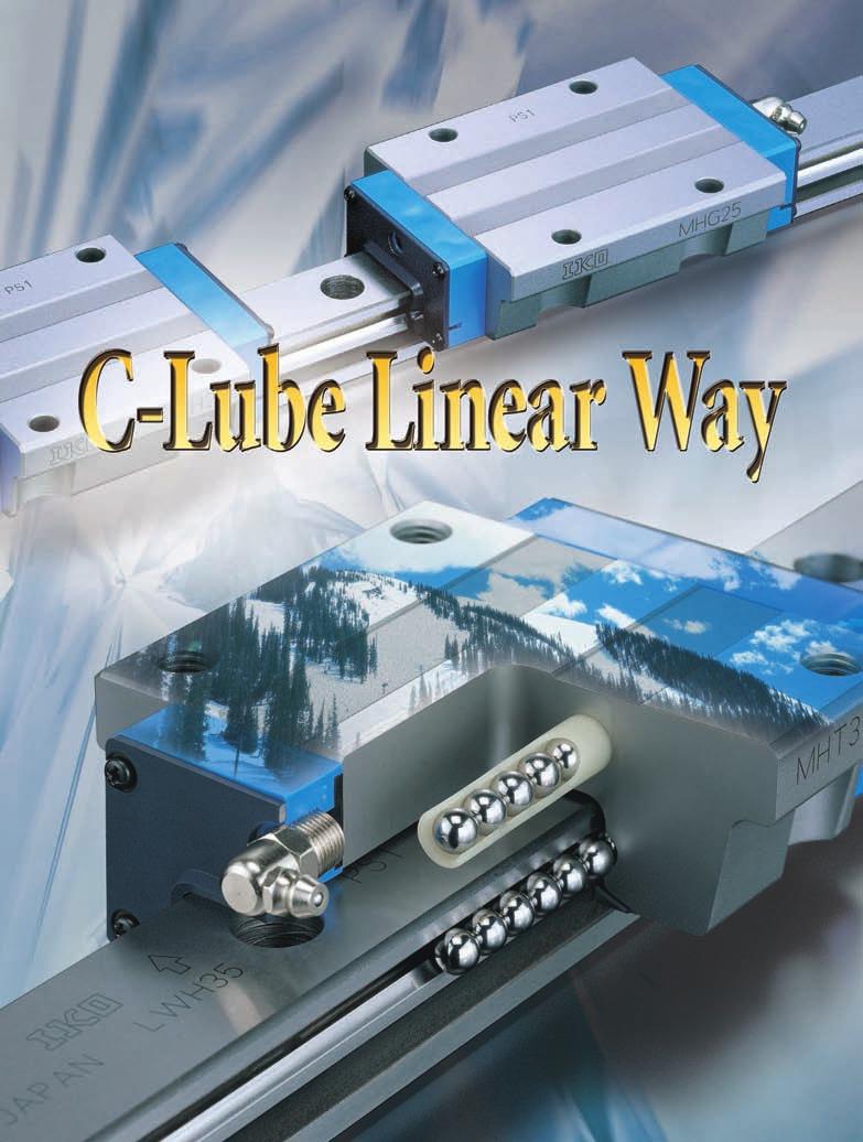
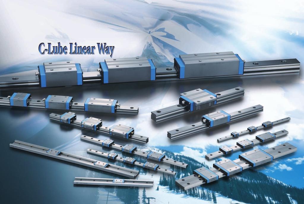
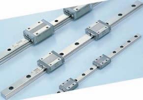
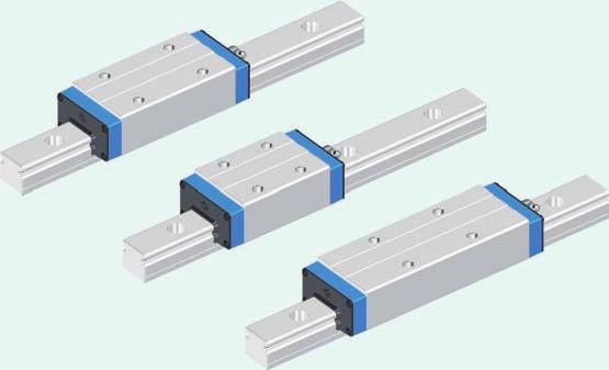
 Maintenance ree & U.S. PTTD C-Lube Linear ay Variation of C-Lube Linear ay Shape Length of slide unit Model code C-Lube Linear ay is a linear motion rolling guide, incorporating the C-Lube as a components
C-Lube Linear Way ML Linear Way L ML LWL
 -Lube Linear ay ML Linear ay L MLLL -Lube Maintenance ree Series -Lube Linear ay ML ML long term maintenance free supported! The aquamarine end plate is the symbol of maintenance free. Identification umber
Slide unit. Casing. Model. 3 Size. Linear Way E LWE. 6 Material type. 9 Interchangeable
 -Lube Maintenance ree Series -Lube Linear Way M M period maintenance free supported! Te aquamarine end plate is te symbol of maintenance free. Identification umber and Specification xample of an identification
General Explanation Ⅲ 1 Ⅲ 2
 General Explanation 1 2 Selection Procedure Selection of Linear Way and Linear Roller Way should be considered from the most important required matter to details in order. Typical procedure is shown below.
Low Decibel Linear Way E
 U.S. PATNTD Low Decibel Linear Way LWQLWTQLWSQ Low Decibel Linear Way series Sape lange type mounted from bottom Low Decibel Linear Way is a linear motion rolling guide for smoot and quiet motion. Its
Miniature (SEB Type) Tapped-Hole rail Types: Slide guides with clearance holes are standard and tapped holes are available upon request.
 Tapped-Hole rail Types: Slide guides with clearance holes are standard and tapped holes are available upon request.") Miniature (SE Type) The SE type slide guide is a linear motion bearing in which the ball elements roll along two tracking grooves. This is the smallest and lightest slide guide series offered by Nippon
Miniature (SE Type) The SE type slide guide is a linear motion bearing in which the ball elements roll along two tracking grooves. This is the smallest and lightest slide guide series offered by Nippon
Points. Precision Positioning Table TU. Variation. Major product specifications With flange
 9 0 Precision Positioning Table Ball screw inear Points lide table with high accuracy and high rigidity in a single structure lide table Compact and slim type positioning table with an original U-shaped
Miniature Slide Guide Series with Retained Ball now Offers Complete Selection
 Miniature Slide Guide Series with Retained Ball now Offers Complete Selection Wide type of Miniature Slide Guide, providing greater allowable moment, is now available with retained ball structure. Due
The basic dynamic load rating C is a statistical number and it is based on 90% of the bearings surviving 50 km of travel carrying the full load.
 Technical data Load Rating & Life Under normal conditions, the linear rail system can be damaged by metal fatigue as the result of repeated stress. The repeated stress causes flaking of the raceways and
Precision Ball Screw/Spline
 58-2E Models BNS-A, BNS, NS-A and NS Seal Outer ring Shim plate Seal Spline nut Seal Collar Shim plate Seal End cap Ball Outer ring Ball screw nut Outer ring Ball Retainer Retainer Outer ring Point of
SLIDE GUIDE SGL TYPE SLIDE GUIDE BLOCK TYPES ACCURACY
 SGL YPE he N slide is a linear motion earing utilizing the rotational motion of all elements along four rows of raceway grooves. It can e used in various applications due to its compactness and high load
SLIDE GUIDE SGL TYPE SLIDE GUIDE BLOCK TYPES ACCURACY
 SGL YPE he N slide is a linear motion earing utilizing the rotational motion of all elements along four rows of raceway grooves. It can e used in various applications due to its compactness and high load
Cam Roller Guides. The Drive and Control Company. Service Automation. Electric Drives and Controls. Linear Motion and Assembly Technologies
 Industrial Hydraulics Electric Drives and Controls Linear Motion and Assembly Technologies Pneumatics Service Automation Mobile Hydraulics Cam Roller Guides The Drive and Control Company Linear Motion
The SynchMotion. Retainer
 106 G99TE13-0809 Linear Guideways QE Series 2-9 QE Type Quiet Linear Guideway, with SynchMotion TM Technology The development of HIIN-QE linear guideway is based on a four-row circular-arc contact. The
Ball screw. Linear. Coupling cover. 1Positioning table of a structure with enhanced sealing property. 3 High corrosion resistance
 Cleanroom Precision Positioning Table TC Ball screw TC EB Slide table inear Way Side cover Stainless sheet Motor bracket inear Coupling cover Pipe threads for suction connector Points ight weight, low
PROCESS FOR SELECTING NB LINEAR SYSTEM
 The NB linear system is a linear motion mechanism which utilizes the recirculating movement of ball or roller elements to provide smooth and accurate linear travel. NB offers a wide range of linear motion
R-Plus System Frontespizio_R_PlusSystem.indd 1 11/06/ :32:02
 R-Plus System R-Plus System R-Plus system R-Plus system description Fig. R-Plus system R-Plus System is Rollon s series of rack & pinion driven actuators. Rollon R-Plus System series linear units are designed
Low Profile Slide Table
 Low Profile Slide Table Series ø, ø, ø1, ø Low-profile and compact type, air slide table with the construction of guide and cylinder aligned in parallel. Neat appearance Protecting stopper section with
Series MHY2/MHW Angular Gripper. Cam actuation style is now standardized! MHZ2 MHZJ2 MHQ MHL2 MHR MHK MHS MHC2 MHT2 MHY2 MHW2 MRHQ 2.
 18 Angular Gripper Cam Style Rack & Pinion Style Series / Cam actuation style is now standardized! 2.8-1 18 Angular Gripper 18 Angular Gripper Series / Cam Style Rack & Pinion Style Series / Series MHY/Cam
1 High precision, high rigidity positioning table
 TSHM CTHM 11 116 Precision Positioning Table H Ball screw TSH M Ball screw Slide table inear Way Bed inear Points 1 High precision, high rigidity positioning table High precision, high rigidity positioning
Monoca rrier TM CBLOCK C1-C22 C23-C68 C69-C88
 C-1 TM 1. Features C1 2. Classifications and Series C. Optional Components C. Selection of.1. Procedures for Selecting C.2. Rigidity C.. Maximum Speed C.. Accuracy Grade C.. Stroke and Ball Screw Lead
SNL plummer block housings, 2, 3, 5 and 6 series Other bearing housings Large SNL plummer block housings
 Bearing housings SNL plummer block housings, 2, 3, 5 and 6 series... 1033 Other bearing housings... 1058 Large SNL plummer block housings... 1058 SONL plummer block housings... 1059 SDG plummer block housings...
MonocarrierTM Monocarrier
 Monocarrier TM Significantly saves designing load of machinery through an integration of linear motion components in one unit. Demonstrates high performance in a wide range of applications, including assembling
FOUR-POINT CONTACT SLEWING RINGS - without gear [ O ]
![FOUR-POINT CONTACT SLEWING RINGS - without gear [ O ]](/thumbs/96/126795264.jpg "FOUR-POINT CONTACT SLEWING RINGS - without gear [ O ]") FOUR-POINT CONTACT SLEWING RINGS - without gear [ O ] Number of the Loading Boundary Dimensions Static Ax.Basic Load Rating Designation Weight Abutment Dimensions Curve d D T C oa G J 1 J 2 N 1 N 2 n 1
FOUR-POINT CONTACT SLEWING RINGS - without gear [ O ] Number of the Loading Boundary Dimensions Static Ax.Basic Load Rating Designation Weight Abutment Dimensions Curve d D T C oa G J 1 J 2 N 1 N 2 n 1
ø6, ø10, ø15, ø20, ø25, ø32, ø40, ø50, ø63 How to Order Switch rail Nil Standard stroke Refer to page 12 for standard stroke.
 Magnetically Coupled Rodless Cylinder: Direct Mount ype Series ø, ø, ø, ø, ø, ø, ø, ø0, ø Direct mount type mm mm mm mm mm mm mm 0 0 mm mm 00 MB Piping type Both sides piping type Centralized piping type
Drive Units with Ball Screw Drives R310EN 3304 ( ) The Drive & Control Company
 The Drive & Control Company") Drive Units with Ball Screw Drives R310EN 3304 (2007.05) The Drive & Control Company Linear Motion and Assembly Technologies Ball Rail Systems Roller Rail Systems Linear Bushings and Shafts Precision Ball
Drive Units with Ball Screw Drives R310EN 3304 (2007.05) The Drive & Control Company Linear Motion and Assembly Technologies Ball Rail Systems Roller Rail Systems Linear Bushings and Shafts Precision Ball
Must Read Before Installation TadPoleTM Safety and Warnings
 Must Read Before Installation TadPoleTM Safety and Warnings The recommendations, requirements, rules, and instructions of your Vehicle's Roof-Top Rack System should ALWAYS be followed. The TadPole TM,
ER2 Short-head Electric Chain Hoist
 O/M NO.SHER2-0903-CE-00 ER2 Short-head Electric Chain Hoist (250kg to 5t) Operation Manual (SHER2M/SHER2SG/SHER2SP) Introduction The KITO Short-head Electric Chain Hoist is intended for effective use in
Important Instructions
 Important Instructions Subject Use With Cabinet Hardmount Trunnion Replacement Cabinet Hardmount 8-60 Pound Washer-Extractors and Kits F77000, F7700, F7700, F7700, F7700, F7700, F9P and F9P WARNING This
General Explanation Ⅲ 1 Ⅲ 2
 General Explanation 1 2 Load Rating and Life Life of linear motion rolling guides Even in normal operational status, a linear motion rolling guide will reach the end of its life after a certain period
Bettis RGS F-Series. Quarter-Turn Spring-Return (SR) and Double-Acting (DA) Pneumatic Actuators. Product Data Sheet RGS Rev.
 and Double-Acting (DA) Pneumatic Actuators. Product Data Sheet RGS Rev.") Bettis RGS F-Series Quarter-Turn Spring-Return (SR) and Double-Acting (DA) Pneumatic Actuators Output Torques to 500,000 in-lb (56,492 N m) Ductile Iron or Stainless-Steel Construction Temperatures from
Bettis RGS F-Series Quarter-Turn Spring-Return (SR) and Double-Acting (DA) Pneumatic Actuators Output Torques to 500,000 in-lb (56,492 N m) Ductile Iron or Stainless-Steel Construction Temperatures from
E8EB-N0C2B E8EB-N0B2B
 Slim Sensor CSM DS_E 1 Ideal for Workpiece Position and Original Checking The to 1 kpa model can be used for workpiece position checking. The to 1MPa model is ideal for original pressure checking. Degree
Type Plunger Height x pitch Operating force (OF) Without ground terminal Flat type 4.3 x 6.5 mm General 0.98 N (100 gf) B3F-6000 B3F-6100
 Without ground terminal Flat type 4.3 x 6.5 mm General 0.98 N (100 gf) B3F-6000 B3F-6100") Mechanical Key Switch (Ral) B3F- Taped Ral Switches Automatic mounting possible via general- ral taped component inserters. Conform to EIAJ RC 1008A Electronic Component Taping Dimensions. The same snap-action
Mechanical Key Switch (Ral) B3F- Taped Ral Switches Automatic mounting possible via general- ral taped component inserters. Conform to EIAJ RC 1008A Electronic Component Taping Dimensions. The same snap-action
Linear Guides SH Series
 inear Guides S Series Ball Slide Models: A, B Front view of A and B types Side view of B type MRO B1 W B 4-M l 1 T MYO K E B 3 W2 W1 Model o. SA SB SA SB S2A S2B SA SB S3A S3B S4A S4B SA SB Assembly Ball
Product Description. Further highlights. Outstanding features. 4 Bosch Rexroth Corporation Miniature Linear Modules R310A 2418 (2009.
 4 Bosch Rexroth orporation Miniature Linear Modules R310A 2418 (2009.05) Product Description Outstanding features Rexroth Miniature Linear Modules are precise, ready-to-install linear motion systems that
CTV series CHARACTERISTICS LINEAR UNITS
 CTV series CHARACTERISTICS The CTV series describes s with a precision ball screw drive and two parallel, integrated, Zerobacklash rail guides. Compact dimensions allow high performance features such as,
flexible couplings for pipe repair
 A R P O L R E P flexible couplings for pipe repair 1 TABLE OF CONTENTS Advantages and Installation Arpol Repair Systems Nominal charts Material specifications Gaps between pipe ends Outside Diameter tolerances
Connector~Tech Providing Harsh Environment Connector
 Connector~Tech www.connectortech.com.au Providing Harsh Environment Connector SOLUTIONS Tajimi TC18 series connectors are water-pro up to 30 meters in depth. Economical and highly reliable construction
180 Angular Gripper. Series MHY2/MHW2. Cam actuation style is now standardised! 5-241
 18 Angular Gripper Cam tyle Rack & Pinion tyle eries MHY2/MHW2 Cam actuation style is now standardised! -21 18 Angular Gripper Cam tyle Rack & Pinion tyle eries MHY2/MHW2 eries MHY/Cam tyle Light and compact
ADVANCED MOTION TECHNOLOGIES CORP.
 LINEAR GUIDEWAY ADVANCED MOTION TECHNOLOGIES COR. No.7, Lane 89, Chung Shan Rd., Shen Kang Hsiang, Taichung Hsien 49, Taiwan TEL: +886464 FAX: +8864686 Email: amt.info@pmiamt.com.tw Web site: www.pmiamt.com
STAF Linear Guide. STAF Linear Guide Integrated Rail for Non Cage Type and Cage Type.
 STAF Linear Guide STAF Linear Guide Integrated Rail for Non Cage Type and Cage Type www.staf.com.tw A. Terms of Linear Guide 1-1 Main Factors a. Lifetime and Load of Linear Guide Selection of linear guide
ORTHOBLOC 3000 Drive systems Maintenance
 15 en 284 261 282 113 130 120 061 002 264 193 099 001 25 063 65 119 112 133 252 254 1 115 118 04 ORTHOBLOC 3000 Maintenance NOTE LEROY-SOMER reserves the right to modify the characteristics of its products
Installation, Maintenance and Operating Instructions
 Trunnion-Design Ball Valves 12 20 (DN 300 500) Series 7150 12 (DN 300) Series 730S 12 20 (DN 300 500) Series 7300 14 24 (DN 350 600) Series 9150 14 24 (DN 350 600) Series 9300 Installation, Maintenance
Ball Reverser. Ball Reverser Actuator. FLENNOR Power Transmission Products. Patented
 Ball Reverser FLENNOR Power Transmission Products Ball Reverser Actuator Patented Ball Reverser Principle General Information NORCO'S Ball Reverser Actuator is a unique actuator which provides automatic
HEAVY DUTY SWING-OUT VALVE
 ISO 900 REGISTERED COMPANY Akron Brass Company. 20 All rights reserved. No portion of this can be reproduced without the express written consent of Akron Brass Company. We will not be responsible for:
Identification system for short product names. Changes/amendments at a glance. 2 Bosch Rexroth AG OBB omega modules R ( )
") Omega Modules OBB 2 OBB omega modules R9990079 (206-05) Identification system for short product names Short product name Example: O B B - 085 - N N - System = Omega module Guideway = Ball Rail System Drive
Omega Modules OBB 2 OBB omega modules R9990079 (206-05) Identification system for short product names Short product name Example: O B B - 085 - N N - System = Omega module Guideway = Ball Rail System Drive
Peltier Application Note
 Peltier Application Note Early 19th century scientists, Thomas Seebeck and Jean Peltier, first discovered the phenomena that are the basis for today s thermoelectric industry. Seebeck found that if you
Load Washers. Force. for Forces of 7, kn. F z. Type 9001A A 9081B, 9091B
 Force Load Washers for Forces of 7,5... 1 200 kn Type 9001A... 9071A 9081B, 9091B 1-component force sensor for measuring dynamic and quasistatic forces in z direction. F z Calibrated measuring range 100
HEAVY DUTY SWING-OUT VALVE
 ISO 900 REGISTERED COMPANY HEAVY DUTY SWING-OUT VALVE 52 53 23 5 2 2 3 28 39 NOT USED WITH SZ HANDLE 2 NOT USED WITH SZ HANDLE 5 2 3 7 9 9 Premier Farnell Corporation. 20 All rights reserved. No portion
ATV WP2 FRONT MOUNT PUSH TUBE
 ATV WP2 FRONT MOUNT PUSH TUBE ASSEMBLY / OWNER S MANUAL Part No: 16-0000 MAN0352 Rev. 00 OPERATING INSTRUCTIONS Congratulations! You ve just purchased the most durable plow component in the industry. Cycle
product manual H-4204 Proving Ring Penetrometer
 05.09 product manual H-4204 Proving Ring Penetrometer nnmm Handle Proving Ring Extension Rod Coupler Penetration Rod Cone Figure #1 General Information The Proving Ring Penetrometer is a cone type of penetrometer
Identification Number. Accuracy. Clearances. Examples of identification number. Table 3 Radial internal clearance. Table 1 Tolerances
 Identiication umber Accuracy learances The identiication number example o Hex Head am Followers are shown below. Examples o identiication number Tolerances o Hex Head am Followers are shown in Table and
DRIFTER PLOW-IN-A-BOX ASSEMBLY / OWNER S MANUAL
 DRIFTER PLOW-IN-A-BOX ASSEMBLY / OWNER S MANUAL Part No: 10-0550 OPERATING INSTRUCTIONS Congratulations! You ve just purchased one of the industry s top plow systems. The DRIFTER Plow System works great
Product description. Compact Modules. Characteristic features. Further highlights
 4 Compact Modules Product description Characteristic features Five fine-tuned sizes based on a compact precision aluminum profile with two integrated pre-tensioned ball rail systems Identical external
THE LOSMANDY G-11 MOUNT
 Checking the parts THE LOSMANDY G-11 MOUNT Depending on which accessories you ordered, your G-11 mount was shipped in four or more boxes. The contents of each box are as follows: Equatorial Mount Adjustable
PLOW MOUNT KIT FOR POLARIS RANGER P/N ASSEMBLY / OWNERS MANUAL
 PLOW MOUNT KIT FOR POLARIS RANGER P/N 34-3010 ASSEMBLY / OWNERS MANUAL Application PLOW PUSH FRAME NO. 34-0000 or 34-0070 Before you begin, please read these instructions and check to be sure all parts
Proximity Sensor Ideal for High Temperatures and Cleaning Processes. Applicable to 120 C
 ASH & ALAIN INDIA PVT LTD S-00, F.I.E.E., Okhla Industrial Area, Phase-ii, New Delhi-000(India) Tel : 0-797575 Fax : 0-79757 E-mail : sales@ashalain.com Proximity Ideal for High Temperatures and Cleaning
INSTALLATION INSTRUCTIONS ATV Plow Blade Part Number: (50 ), (54 ), or (60 ) Application: All Terrain Vehicles
, (54 ), or (60 ) Application: All Terrain Vehicles") INSTALLATION INSTRUCTIONS ATV Plow Blade Part Number: 78950 (50 ), 78954 (54 ), or 78960 (60 ) Application: All Terrain Vehicles Your safety, and the safety of others, is very important. To help you make
INSTALLATION INSTRUCTIONS ATV Plow Blade Part Number: 78950 (50 ), 78954 (54 ), or 78960 (60 ) Application: All Terrain Vehicles Your safety, and the safety of others, is very important. To help you make
Bearing Internal Clearance and Preload
 . Bearing Internal Clearance and Preload. Bearing internal clearance Bearing internal clearance is the amount of internal free movement before mounting. As shown in Fig.., when either the inner ring or
Uncertainty Analysis of Experimental Data and Dimensional Measurements
 Uncertainty Analysis of Experimental Data and Dimensional Measurements Introduction The primary objective of this experiment is to introduce analysis of measurement uncertainty and experimental error.
Conversion Kit for: 7620 and 7820 Swing-Out Valves ft-lbs ft-lbs 8835/ ft-lbs
 ISO 900 REGISTERED COMPANY HEAVY DUTY SWING-OUT VALVE 52 53 23 5 2 2 3 28 39 NOT USED WITH SZ HANDLE 2 NOT USED WITH SZ HANDLE 5 2 3 7 9 9 Premier Farnell Corporation. 20 All rights reserved. No portion
LINE TECH Linear Modules. Ready to built-in linear modules with drive
 Ready to built-in linear modules with drive Anodized profile, produced in extrusion molding method Linear rail guiding system (LM3 LM5) Actuation by ball screw, high-helix lead _ screw or toothed belt
DISCONTINUED PRECISION MEASURING FOWLER CALIPERS 1 - VERNIER CALIPERS 4 - ELECTRONIC CALIPERS
 FOWLER CALIPERS 1 - VERNIER CALIPERS 4 - ELECTRONIC CALIPERS 52-058-016 Fine quality vernier calipers are constructed of stainless steel. 52-057-004 offers 3-way measurement to accuracy. 52-058-XXX series
Project PAJ2 Dynamic Performance of Adhesively Bonded Joints. Report No. 3 August Proposed Draft for the Revision of ISO
 NPL Report CMMT(A)81 Project PAJ2 Dynamic Performance of Adhesively Bonded Joints Report No. 3 August 1997 Proposed Draft for the Revision of ISO 11003-2 Adhesives - Determination of Shear Behaviour of
TE 75R RESEARCH RUBBER FRICTION TEST MACHINE
 TE 75R RESEARCH RUBBER FRICTION TEST MACHINE Background: The Research Rubber Friction Test Machine offers the ability to investigate fully the frictional behaviour of rubbery materials both in dry and
ENGINEERING INFORMATION TABLE OF CONTENTS SHAFT AND HOUSING FITS LUBRICATION LIFE AND LOAD RATINGS RADIAL CLEARANCE CHART
 ENGINEERING INFORMATION TABLE OF CONTENTS ENGINEERING INFORMATION SHAFT AND HOUSING FITS LUBRICATION LIFE AND LOAD RATINGS RADIAL CLEARANCE CHART SHAFT AND HOUSING FITS FOR METRIC RADIAL BALL AND ROLLER
Reference Only. Spec. No. JENF243G 0004G-01 P 1 / 12. Ferrite Bead Inductor BL02/BL03 Series
 Spec. No. JENF243G 0004G-01 P 1 / 12 1. Scope Ferrite Bead Inductor B02/B03 Series Reference Specification This reference specification applies Ferrite Bead Inductor (Radial Type). 2. Part Numbering (Ex.)
Tangential Fans Series TW Impeller diameter 150 mm and 200 mm
 Tangential Fans Series TW Impeller diameter mm and 0 mm 105 Corporate Drive, Suite E Spartanburg, SC 293 PO Box 2889, Spartanburg, SC 294 USA Tel: 864-599-63 Fax: 864-599-6344 e-mail: info@ltg-inc.net
SOLUTION (17.3) Known: A simply supported steel shaft is connected to an electric motor with a flexible coupling.
 Known: A simply supported steel shaft is connected to an electric motor with a flexible coupling.") SOLUTION (17.3) Known: A simply supported steel shaft is connected to an electric motor with a flexible coupling. Find: Determine the value of the critical speed of rotation for the shaft. Schematic and
SOLUTION (17.3) Known: A simply supported steel shaft is connected to an electric motor with a flexible coupling. Find: Determine the value of the critical speed of rotation for the shaft. Schematic and
Selection Calculations For Linear & Rotary Actuators
 H-8 For Electric Linear Slides and Electric Cylinders First determine your series, then select your product. Select the actuator that you will use based on the following flow charts: Selection Procedure
Lever-type Dial Test Indicators
 Lever-type Dial Test Indicators G-1 Lever-type Dial Test Indicators TESA IP65 Electronic Dial Test Indicators Provides the advantages of a mechanical test indicator with a digital reading. Inductive patented
The SKF model for calculating the frictional moment
 The SKF model for calculating the frictional moment The SKF model for calculating the frictional moment Bearing friction is not constant and depends on certain tribological phenomena that occur in the
/2" Heavy Duty Swing-Out
 Premier Farnell Corporation. 0 All rights reserved. No portion of this can be reproduced without the express written consent of Premier Farnell Corporation. ISO 900 REGISTERED COMPANY We will not be responsible
ERB Series. High Frequency Ceramic Capacitors. ERB Product Summary
 ERB Product Summary : Exhibiting a capacitance range of 0.5 to 1,000pF, the ERB series of capacitors comes with higher Q and lower ESR which is better than the standard products of equivalent packages.
ROTARY MOTION CONTROL
 ROTARY MOTION CONTROL Technical Data Sheet Nexen Mechanical Torque Limiter Family PMT / PMK / PMC 2TC 2CC ECC PCC Mechanical Torque Limiter The trend in industry is to design and incorporate more automation
Richter Optica. Instructions for Model: S850 Stereo Zoom Microscope
 Richter Optica info@richter-optica.com Instructions for Model: S850 Stereo Zoom Microscope Microscope Head Focus Knob Stage Clips Zoom Knob C-Mount Adapter Eyepiece Focusing Holder Focusing Holder Set
MODEL NAME : LLDMWW0-15K*0*A
 Eagle Eye (Outdoor LED Module) Application Note MODEL NAME : LLDMWW0-15K*0*A RoHS Compliant HALOGEN FREE (30)-4022 1 / 16 CONTENTS 1. Product Description 3/16 2. Specifications 2.1. Chromaticity Bins for
Electron Microscopy Sciences INSTRUCTION MANUAL. Stereo Microscopes Non-illuminated Stands
 Electron Microscopy Sciences 1 INSTRUCTION MANUAL Stereo Microscopes Non-illuminated Stands Model GL7-207: Binocular, 6.5:1 Zoom Ratio 10X to 65X, smooth ball bearing construction and Model GL7-307: Trinocular,
Rodless cylinders Series 1600
 Rodless cylinders Series 00 Basic version 0.Ø.stroke.0.M Max. stroke mt.) AL AI RA RB AF TC AM L LA+stroke AH TD AE TA RV Possibility of a single feed cylinder head AI AP AB AC AD TD TE TB AG RT Left head
TURQUOISE SWITCHES V TYPE (ABV)
") HIGH ENVIRONMENTAL RESISTANCE TURQUOISE SWITCHES V TYPE (ABV) FEATURES Miniature size (33 15.9.3 mm) (99.626.406 inch) Sealed construction for use in adverse environment Sealed construction by epoxy resin
HIGH ENVIRONMENTAL RESISTANCE TURQUOISE SWITCHES V TYPE (ABV) FEATURES Miniature size (33 15.9.3 mm) (99.626.406 inch) Sealed construction for use in adverse environment Sealed construction by epoxy resin
 Selection of jack size No. 5 Check again with ball screw jack Type J-B. Yes. Set the hand wheel radius if the screw jack is to be used for manual operation. Yes. Yes. Specification Select temporarily the
Section 8 Column radiators
 Section s Description Connections Standard without built-in valve -or- Version with built-in valve Air vent, Drain Fixing and mounting Pressure versions, Fittings, Surface finishes, Special versions eat
TABLE OF CONTENT Scope 2 Alignment Systems and Procedures 2 Balancing 8 Lubrication System 10 Preservation of Spare Parts 12
 Page : 1 of 21 Project Engineering Standard www.klmtechgroup.com KLM Technology #03-12 Block Aronia, Jalan Sri Perkasa 2 Taman Tampoi Utama 81200 Johor Bahru Malaysia TABLE OF CONTENT Scope 2 Alignment
Multilayer Ceramic Chip Capacitors
 HIGH VOLTAGE SERIES JARO high voltage series Multilayer Ceramic Capacitors are constructed by depositing alternative layers of ceramic dielectric materials and internal metallic electrodes, by using advanced
SMD Switch SI-C3436A General specification. Soldering conditions Reflow Soldering condition. Standard Reel Dimensions (mm) Packing specification
 Packing specification") SMD Switch SI - C3436A - 7017 Features External Dimensions : 3.4mm x 3.6mm, Height 0.70mm Suitable for thinner and lighter portable devices Suitable for water proof devices Reflow soldering Package With
SMD Switch SI - C3436A - 7017 Features External Dimensions : 3.4mm x 3.6mm, Height 0.70mm Suitable for thinner and lighter portable devices Suitable for water proof devices Reflow soldering Package With
Modular Style Air Combination. Assembled by simply tightening the screws
 Modular Style Air Combination Series AC Assembled by simply tightening the screws High strength die cast bracket Drain cock for one push drain exhaust Oil needle for easy oil volume adjustments The improved
Lever-type Dial Test Indicators
 Lever-type Dial Test Indicators www.tesatechnology.com G-1 Lever-type Dial Test Indicators TESA IP65 Electronic Dial Test Indicators Provides the advantages of a mechanical test indicator with a digital
AME Model. (1) Rated flow (l/min (ANR)) Port size (Nominal size B) Weight (kg)
 Rated flow (l/min (ANR)) Port size (Nominal size B) Weight (kg)") Super Mist Separator Series AME Series AME separates and absorbs aerosol state fine oil particles in compressed air and changes the oil lubricating compressed air to oilless equivalent air. It should be
Super Mist Separator Series AME Series AME separates and absorbs aerosol state fine oil particles in compressed air and changes the oil lubricating compressed air to oilless equivalent air. It should be
flexible couplings for pipe connections
 www.arpol.com A R P O L INSTAL flexible couplings for pipe connections 1 TABLE OF CONTENTS Advantages & installation 3 Sealing system & applications Nominal charts Material Specifications Gaps between
Wenzhou Tripod Instrument Manufacturing Co., Ltd.
 Wenzhou Tripod Instrument Manufacturing Co., Ltd. Website: http://aliyiqi.en.alibaba.com http://www.wzydyq.com/english/ Phone: 86-577-57572515 57572515 Fax: 86-577-57572516 57572516 E-mail: aliyiqi@gmail.com
SL27C SL32C. ScreenLine. Technical Catalogue. english. double-glazed unit 27 mm 32 mm
 VENETIAN SL27C SL32C BLIND english Technical Catalogue double-glazed unit 27 mm 32 mm dimensions technical specification SL27C SL32C System C C SL27C VENETIAN SL32C BLIND The venetian blinds SL27C and
Linear Motion Slides. The Drive and Control Company. Service Automation. Electric Drives and Controls. Linear Motion and Assembly Technologies
 Industrial Hydraulics Electric Drives and Controls inear Motion and ssembly Technologies Pneumatics Service utomation Mobile Hydraulics inear Motion Slides The Drive and Control Company The Product Range
Automatic Level Maintenance Manual SAL-XX W/ AIR DAMPENED COMPENSATOR
 Automatic Level Maintenance Manual SAL-XX W/ AIR DAMPENED COMPENSATOR CST/Berger 2001 SAL 20/24/28/32 PAGE 1 REV. C 071803 Automatic Level Maintenance Manual User Calibration and Testing... 3 Circular
second PLSA line R310EN 3308 ( )
") 01_1 Planetary st Headline_36 Screw Assemblies pt/14.4 mm second PLSA line R310EN 3308 (2011-09) 2 Planetary Screw Assemblies PLSA Planetary Screw Assemblies PLSA Product Overview 3 Nuts, Screws, Screw
01_1 Planetary st Headline_36 Screw Assemblies pt/14.4 mm second PLSA line R310EN 3308 (2011-09) 2 Planetary Screw Assemblies PLSA Planetary Screw Assemblies PLSA Product Overview 3 Nuts, Screws, Screw
Model 791 Calibration Plate for Tiltmeters and Inclinometers
 User s Manual Model 791 Calibration Plate for Tiltmeters and Inclinometers Serial No. Baseline, L Date measured By mm Introduction The Model 791 Calibration Plate is designed for calibrating any tiltmeter
Kalinka Optics Warehouse User Manual Kobra AK Side Mount Red Dot Sight Manual
 Kalinka Optics Warehouse User Manual www.kalinkaoptics.com Kobra AK Side Mount Red Dot Sight Manual CONTENTS 1. Introduction... 4 2. Purpose... 4 3. Specifications... 4 4. Components and Equipment Provided...