Structural Mechanics Column Behaviour
|
|
|
- Matthew Potter
- 6 years ago
- Views:
Transcription
1 Structural Mechanics Column Behaviour 008/9 Dr. Colin Caprani, 1
2 Contents 1. Introduction Background Stability of Equilibrium Buckling Solutions Introduction Pinned-Pinned Column Column with Initial Displacements The Effective ength of Columns Column Design Background to BS Column Design Examples Appendix Solutions to Differential Equations Code Extracts Past Exam Questions... 6

3 1. Introduction 1.1 Background In the linear elastic analysis of structures, we have assumed that compression members are limited in load capacity in the same way that tension members are, by ensuring the yield stress of the material is not exceeded. However, as can easily be checked with a ruler, compression members often fail long before the material yields due to buckling. So our problem is to identify reduced stress limits that should apply for compression members so that buckling does not occur. The first person to study this problem was Euler ( oil-er ) as a means to demonstrate his ability to solve differential equations. Some of the important results in buckling retain his name. eonhard Euler ( ) 3
4 1. Stability of Equilibrium A structure will be in an initial equilibrium position. The stability of its equilibrium can be assessed by examining the structure s behaviour in an adjacent position. There are three states: Stable equilibrium: the structure tends to return to its initial position. This is the best situation to have structures in. Neutral (or critical) equilibrium: the structure moves to a displaced configuration and remains in that position. This does not make for good structure. Unstable equilibrium: any movement from the initial position causes further movement resulting in a runaway failure of the structure. 4
5 In relation to columns, the stability of equilibrium takes the form: Stable: deflections to not result in extra bending moments, and hence extra deflections. Critical P= P : the load is at a critical value where the column remains in any cr displaced position. Unstable P> P : the load is greater than the critical load and so divergent cr displacements occur, leading to failure. These situations look like this: 5
6 . Buckling Solutions.1 Introduction A perfect column (perfectly straight) is one which is perfectly straight and so carries axial load up to the yield stress of the material. Since in reality columns are not perfectly straight, buckling occurs: In our solutions for buckling, we will find that both the perfectly straight and buckled profiles are both possible theoretically. However, since it is the real behaviour that is of interest, we will focus on the buckled solutions. 6
7 . Pinned-Pinned Column Formulation Firstly, consider the buckled configuration of a pin-ended column and draw a free body diagram of part of the column: From this we see: M = Py 7
8 So for equilibrium: M + Py = 0 We know from Euler-Bernoulli bending theory that: M d y = EI dx And so we have: EI d y Py 0 dx + = (1) Dividing across by EI gives: d y P + 0 y = dx EI If we make the substitution: k = () EI P We then have: d y ky 0 dx + = (3) 8
9 This is a second-order linear homogenous differential equation in y. We seek a solution for y which will be some function of x. The Appendix shows that the general solution to this equation is: y= Acoskx+ Bsin kx (4) where A and B are constants to be evaluated from the boundary conditions of the problem. 9
10 Relevant Solution To get the particular solution to our problem, we know that we have no deflection at the pinned end, that is: At x = 0, y = 0 Substituting this into equation (4): 0= Acosk0+ Bsink0 Since cos( 0) = 1 and sin( 0) = 0, we have: ( ) B( ) 0= A A = 0 Thus equation (4) becomes: y= Bsin kx (5) Using the second boundary condition, at x = y, = 0, we have: 0= Bsink (6) There are two possibilities now. The first is B = 0 which makes y = 0 by equation (5). This means that a possible solution is for no buckling to occur, in other words, the perfect column. Since we know that this is highly unlikely, and that buckling doesn t occur, we must consider the other possibility from equation (6): 10
11 sin k = 0 (7) We know that this only happens at values of: k = 0, π, π,3 π,... = nπ where n = 0,1,,3,.... Therefore we have: k nπ = (8) So from equation () we have: k P = = EI n π And so the critical loads at which the column buckles are: P cr n π EI = (9) Further, by using equation (8) in equation (5) the buckled shape is got as: y Bsin n π = x (10) 11
12 Euler Buckling oad Since we are interested in the lowest load that the column will buckle at, we use the value n = 1 to find the Euler Buckling oad, P, as: E P E π EI = (11) And we also find the displaced shape from equation (10) as: π y= Bsin x (1) This defines a half sine-wave curve as being the buckled shape of the column. Notice that we have no information about B, the amplitude of the displacement. This is because the column is in neutral equilibrium at P and will be in equilibrium at any E displacement amount. 1
13 Other Buckling Modes In general we can see that the column can buckle in the shapes: n Critical oad P = cr Infinite P E π EI = 4π EI 9π EI n π EI Mode Shape y = π 0 y= Bsin x Bsin π x 3 π Bsin x Bsin n π x Plot 13
14 However, to achieve these other buckling loads, the lower modes must be prevented from occurring by lateral restraints: 14
15 Critical Stress For design, we are interested in the stress that the material undergoes at the time of buckling the critical stress, σ : cr P π EI σ cr = E = A A (13) ooking at the factor I A, we see that it is a property of the shape of the cross 4 section, and is in units of [ length] [ length] = [ length]. Therefore, we define a new geometric property, r, called the Radius of Gyration as: I r = (14) A And so r has units of length. The radius of gyration can be thought of as a distance from the centroid at which the area of the cross section is concentrated for calculating the second moment of area, I, since by (14), I = Ar (15) The critical stress can now be expressed as: π Er σ = cr And we can see that the dimensional properties of the column are summed up by the factor Ratio, λ, as: r, which represents a ratio of r to. Thus we define the Slenderness 15
16 λ = (16) r Finally then, we have the equation for critical stress as: σ cr π E = (17) λ A plot of the critical stress against slenderness is called a strut curve and looks like: 16
17 As can be seen, at low slendernesses (that is short stocky columns), the critical stress (to cause bucking) reaches very high values. Since the maximum stress in the material is the yield stress, me must cap the curve at σ. y Finally, notice that typical experimental results fall below the Euler strut curve. This is because the theory examined so far is for perfectly straight columns that have somehow begun to buckle. In real columns there will be some initial imperfections which have the effect of reducing the strength of the column. These initial imperfections can be represented by an initial displacement curve. 17
18 .3 Column with Initial Displacements Problem Formulation The imperfections in the manufacture of real columns mean that an initial displacement curve exists in the column, prior to loading. Since any curve can be represented by a Fourier series expansion, we will approximate the initial displaced shape by the first term of a Fourier series a sine curve, the equation of which is: π y0 ( x) = asin x (18) where, at the midpoint of the column, the initial displacement is a. 18
19 Considering a free-body diagram as before: gives the equilibrium equation as: Thus we have: d y ( 0 ) 0 EI P y y dx + + = d y P P + y+ y = 0 0 dx EI EI Using equation () gives: 19
20 d y ky ky 0 0 dx + + = And so using equation (18) we have π x + = (19) d y ky kasin dx This is a non-homogenous second order differential equation. 0
21 Solution The solution to non-homogenous differential equations is made up of two parts: The complimentary solution (denoted y ): this is the solution to the C corresponding homogenous equation. That is, the solution when the right hand side is zero. We have this from before as equation (4): y = Acoskx+ Bsin kx (0) C The particular solution (denoted y P ): for the function on the right hand side, the solution is verified in the Appendix as: y P ka π x = sin π + k ka π x = sin π k (1) Thus the total solution is: y= y + y C P ka π x = Acoskx+ Bsin kx+ sin π k () To find the constants, we know that for the pinned-pinned column, y = 0 at x = 0: 1
22 ka ( 0) = cos ( 0) + sin ( 0) + sin ( 0) y A k B k 0 = A π k π Also, y = 0 at x =, giving: ka π y B k π k 0= Bsink ( ) = sin ( ) + sin ( ) Although this is the same equation as found for the perfectly straight column, we must consider the implications. If B 0 then sin k = 0 and so k = π as before. This yields k = π, or k = π. Substituting this into equation () means that the third term is infinite and so the deflection is infinite. Since this is impossible for a stable column with P< P, we conclude that B = 0 and we are left with: cr y = π ka k π x sin (3) This equation represents the deflections of the column caused by the loading. The total deflection will be that caused by the loading, in addition to the initial imperfection deflection curve: y = y+ y tot 0 And so:
23 k π x π x y = asin + asin tot π k Solving out, and dropping the tot subscript on y gives:: k π x y= + 1 asin π k And so: π π x y= asin π k (4) Now, using the expression for P (equation (11)), we have: E π = P E EI And with the expression for k (equation ()), equation (4) becomes: y= P EI π x E asin P EI P EI E And so we have: P π x E y= asin P P E 3 (5)
24 The term in brackets thus amplifies the initial deflection, depending on how close we are to the critical buckling load. A plot of load against deflection shows: 4
25 Maximum Stress Consideration At the mid-height of the column, the deflection will be largest, and thus so will the bending moment. The deflection at the mid-height is got from equation (5), with x = : P π E y = asin P P E P a P P E E = We can equally interpret this equation in terms of stresses by dividing each of the Ps by A: σ E y = a σ σ E (6) where σ is the stress associated with the critical Euler load (equation (13)). E Consider again the free-body diagram of the column from mid-height to pin. There are two sources of stress: 1. The stresses due to the moment alone are: σ = Moment Mz I where z is the distance from the neutral axis of the fibre under consideration. 5
26 . The stresses due to the axial force are: σ = Axial P A Thus the stresses at any point are given by: σ = P Mz A + I (7) Superposition of the stress diagrams shows this: The maximum stress is on the outside face and is thus: σ = P Mc max A + I (8) where c is the distance from the neutral axis to the inside face of the column. 6
27 Next, into equation (8), we introduce the relevant properties of equation (15) and the fact that M Py( ) = yields: σ max ( ) Pcy = σ + Ar But, from equation (6) we know the displacement at mid height, y( ) : σ Pc σ a E = σ + max Ar σ σ E At failure the maximum stress is the yield stress, σ. The stress associated with the y load P when this occurs is σ. Hence the governing equation becomes: cr σ σ σ c σ a E = + y cr cr r σ σ E cr Giving: σ y ac = σ + cr σ E 1 r σ E σ cr (9) We are looking to find the value of σ cr that solves this equation. At the load corresponding to σ failure occurs. As can be seen, this failure stress is a function of cr the section (through r and c) and the initial imperfection, a, as well as the usual Euler buckling load for the column (through σ ). E 7
28 Critical Stress for Buckling To solve equation (9) for σ we proceed as follows: cr y E y cr cr E cr cr cr E ( ) ( ) cr cr y E E y E ac σ E σ = σ 1 y cr + r σ σ E cr σ r σ σ = σ r σ σ + acσ σ ( ) ( ) σσ r σσ r σ σ r + σ σ r acσ σ = 0 σ r + σ σ r σ r acσ + σ σ r = 0 y E cr cr E cr cr E σ σ r σ σ r = σ σ r σ σ r + acσ σ ac σ + σ cr cr σ σ σ y E E + σσ 0 y E = r y E y cr cr E cr cr cr E We call the parameter that accounts for the initial imperfections called the Perry Factor: ac η = (30) r And this gives: ( ) σ + σ 1 0 cr cr σ σ + η σ σ y E + = (31) y E This is a quadratic equation in σ and so is solved by the usual: cr x = b b 4ac ± a where: 8
29 a = 1 y E ( 1 ) b = σ σ + η y E c = σσ And this gives: ( 1 ) ( 1 ) σ + σ + η y E σ + σ + η y E σ = σ σ cr y E 0.5 (3) Notice that we have chosen the lower root of the two possible solutions. Equation (3) is called the Perry-Robertson formula and it gives the buckling stress in terms of the yield stress and initial imperfections of the column, as well as its Euler buckling load. It is useful to introduce the following: ( 1 ) σ + σ + η y E φ = (33) And so the Perry-Robertson formula (equation (3)) becomes: σ = φ φ σ σ (34) cr y E 9
30 .4 The Effective ength of Columns So far we have only considered pinned-end columns but clearly other end conditions are possible. Analysis of the buckling loads for such columns can be carried out along the same lines as for pinned-end columns. However, a significant advantage can be got by remembering that a point of contraflexure (zero moment) behaves as a pin (zero moment). The distance between points of contraflexure can be considered as a pin-pin column, but with a smaller length than the overall column. We call this length the effective length, using the effective, rather than actual, length.. Analysis then proceeds as for pinned-end columns, but E The effective lengths of some typical columns are: Non-Sway Modes Pin-Pin Fix-Pin Fix-Fix 30
31 Sway Modes Fix-fix Fix-roller Cantilever (fix-free) Notice from the above that the locations of the points of contraflexure do not have to be and can be located outside the column. That is, the column is buckling over a notional length of. E The effective length only affects the slenderness and so the general case for slenderness is: λ = E (35) r 31
32 3. Column Design 3.1 Background to BS5950 Initial Imperfections Robertson performed many tests on struts to arrive at a suitable value for the initial imperfections in the approach outlined in the previous section. He suggested: η = 0.003λ (36) where λ is the slenderness of the column, given by equation (16). More recently, the initial imperfection has been taken as: λ η = (37) The idea of linking the initial imperfections to the slenderness is intuitively appealing the slimmer a column is, the more likely it is to have imperfections. The steel design code BS5950 is based on the following: η ( λ ) a λ 0 = (38) 1000 In which: a is the Robertson constant (and is not the same as the a we had for the deflection of the column previously); λ is called the limiting slenderness as is given by: 0 3
33 π E λ = 0. (39) 0 σ y By rearranging equation (17) it can be seen that this is: λ = λ 0 0. cr where λ is the slenderness at which the Euler stress reaches the yield stress of the cr material. As can be seen, the higher the value of a, the more initial imperfection is accounted for and the compressive strength reduces as a result. 33
34 Code Expressions In BS5950, the Perry-Robertson formula is given in a slightly different form to that presented in equation (34). To get the code expression, we multiply top and bottom of equation (34) by φ + φ σ σ to get: y E σ cr = φ φ σ σ φ + φ σ σ y E y E φ + φ σ σ y E And multiplying out gives: σ cr φ φ + σ σ y E = + φ φ σ σ y E σσ y E = φ + φ σ σ y E astly, to get the code expression, we must use the code notation which is: p p p C y E σ σ cr y σ E So finally we have the expression in Appendix C of BS5950: p p p E y = (40) c φ + φ p p E y 34
35 Strut Curves BS5950 provides four values of the Robertson constant that may be used in design. It also specifies what value of a to use for the various types of steel section and the axis about which buckling may occur. The values are: a =.0 - strut curve (a); a = strut curve (b); a = strut curve (c); a = strut curve (d). Given the initial imperfection model of equation (38) as well as the Perry-Roberston formula, equation (40), we can plot the four strut curves used in the code: Compression Strength (N/mm ) Euler a = a = 3.5 a = 5.5 a = Slenderness λ Also shown in this plot are the limiting slenderness, and the critical slenderness, discussed in relation to equation (38). 35
36 The code provides four tables (Table 4(a) to 4(d)) corresponding to the strut curves, which are formatted as follows: p y λ Values of p from equation (40) c Table 3 of the code allocates the strut curves to different section types and axes: 36
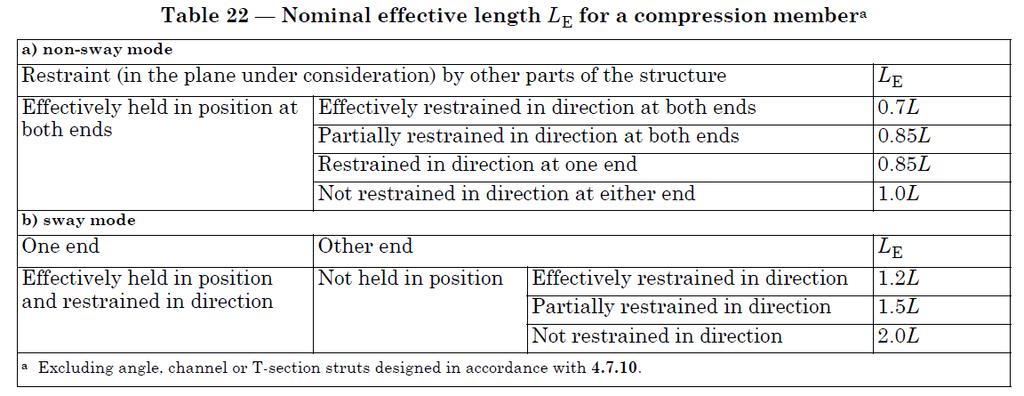
37 Effective engths Table of the code specifies the appropriate effective lengths for columns with different end conditions, end conditions that occur in practice. The meanings of the phrases in Table are as follows: Term Effectively held in position, not restrained in direction. (pin) Diagram Effectively held in position, partially restrained in direction. (rotational spring) Effectively held in position and restrained in direction. (fixed) Not held in position, and effectively restrained in direction. (fixed with sway) Not held in position, partially restrained in direction. (rotational spring with sway) Not held in position or restrained in direction. (free) 37
38 3. Column Design Examples Example 1 Problem A 5.6 m high column consists of a UC section. It is supported along its x-axis and is pinned at both ends. Find the buckling load. Solution Firstly, sketch the column: 38
39 Since the column is supported along its x-x axis, it can only buckle about its y-y axis. The relevant section properties for a UC are: Cross-Sectional Area 58.8 cm Yield stress 75 N/mm Modulus of Elasticity 05 kn/mm Radius of gyration about the y-y axis 5.1 cm Robertson Constant for the y-y axis 5.5 Thus: 5600 λ = = From Table 3 we see that we are using strut curve (c) and so a = 5.5. Also, E = 05 kn/mm and p = 65 N/mm from Table 9. Thus: y The limiting slenderness (equation (39)) is: 3 π E π λ = 0. = 0. = p 65 y The Perry Factor (equation (38)) is: ( λ ) ( ) a λ η = = = The Euler stress (equation (17) is: 39
40 p E 3 π E π = = = 168 N/mm λ 110 The modifying stress (equation (33)) is: ( η 1) pe 65 ( ) 168 p + + y + + φ = = = 59 N/mm And so the compressive strength (equations (34)or (40)): p c p p E y = = = N/mm φ + φ p p E y Thus the buckling load is: P= A p = = kn g c 3 10 To check this, use Table 4(c), for λ 110 and p = 65 N/mm gives: y p = 108 N/mm and so the capacity is c the previous calculation = 635 kn, which is similar to 40
41 Example Problem For the column of Example 1, the restraint along the x-x axis has to be removed. Determine the buckling capacity. Solution Again, sketch the column: 41
42 Since the column can now buckle about both its x-x axis and y-y axis, we will need to determine the buckling capacity of each axis. Of course the buckling capacity about the y-y axis has already been determined from Example 1, so it remains to find the capacity about the x-x axis. The relevant section properties are: Cross-Sectional Area 58.8 cm Yield stress 75 N/mm Modulus of Elasticity 05 kn/mm Radius of gyration about the x-x axis 8.81 cm Robertson Constant for the x-x axis 3.5 Thus: 5600 λ = = The limiting slenderness is the same as in Example 1 since E nor p change: y λ = The Perry Factor (equation (38)) is: ( λ ) ( ) a λ η = = = The Euler stress (equation (17) is: p E 3 π E π = = = N/mm λ
43 The modifying stress (equation (33)) is: ( η 1) pe 65 ( ) p + + y + + φ = = = 43.3 N/mm And so the compressive strength (equations (34)or (40)): p c p p E y = = = 07.7 N/mm φ + φ p p E y Thus the load to cause buckling about the x-x axis is: P= A p = = g c kn 10 Check this value using Table 4. Since the buckling capacities are: x-x axis: P = 11.5 kn ; y-y axis P = kn ; the column will first buckle about the y-y axis and so its overall buckling capacity is: P = kn 43
44 Example 3 Problem To increase the capacity of the column of Example, the supports in the y-y axis have been changed to fixed-fixed. Determine the buckling capacity. Solution As always, sketch the column: 44
45 We know the buckling capacity about the x-x axis from Example, but since the support conditions for the y-y axis have changed, the buckling capacity about the y-y axis changes. Again the relevant properties are: Cross-Sectional Area 58.8 cm Yield stress 75 N/mm Modulus of Elasticity 05 kn/mm Radius of gyration about the y-y axis 5.1 cm Robertson Constant for the y-y axis 5.5 In this case, since the restraints are fixed-fixed, the effective length is: E = 0.7= = 390 mm Thus the slenderness is: 390 λ = = The limiting slenderness is the same as before, λ 0 = The Perry Factor (equation (38)) is: ( λ ) ( ) a λ η = = = The Euler stress (equation (17) is: p E 3 π E π = = = 345. N/mm λ
46 The modifying stress (equation (33)) is: ( η 1) pe 65 ( 0.3 1) 345. p + + y + + φ = = = 361. N/mm And so the compressive strength (equations (34)or (40)): p c p p E y = = = N/mm φ + φ p p E y Thus the load to cause buckling about the y-y axis is thus: P= A p = = 96.9 kn g c 3 10 Check this value using Table 4. Since the buckling capacities are: x-x axis: P = 11.5 kn - still as per Example ; y-y axis P = 96.9 kn - changed due to new support conditions; thus, the column will first buckle about the y-y axis and so its overall buckling capacity is: P = 96.9 kn Notice that a change in support conditions has resulted in a nearly 50% increase in capacity. 46
47 4. Appendix 4.1 Solutions to Differential Equations The Homogenous Equation To find the solution of: d y ky 0 dx + = (41) we try y= e λx (note that this λ has nothing to do with slenderness but is the conventional mathematical notation for this problem). Thus we have: dy dx d y λx = λe ; = λ e dx λx Substituting this into (41) gives: e k e λx λx λ + = 0 And so we get the characteristic equation by dividing out x e λ : λ + k = 0 From which: λ = ± k Or, 47
48 λ =+ ik; λ = ik 1 Where i = 1. Since these are both solutions, they are both valid and the expression for y becomes: y Ae Ae ikx ikx = + (4) 1 In which A and A are constants to be determined from the initial conditions of the 1 problem. Introducing Euler s equations: ikx e = coskx+ isin kx ikx e = coskx isin kx (43) into (4) gives us: ( cos sin ) ( cos sin ) y = A kx + i kx + A kx i kx 1 Collecting terms: ( ) cos ( ) y= A + A kx+ ia ia sin kx 1 1 Since the coefficients of the trigonometric functions are constants we can just write: y= Acoskx+ Bsin kx (44) Which is the solution presented in equation (4). 48
49 Particular Solution of Non-homogenous Equation We seek here to show the particular solution to the problem: d y sin dx + ky= A λx (45) Is given by: y= Bsin λx (46) From (46): dy dx d y cos ; sin = λb λx = λ B λx dx Substitution into (45) gives: λ Bsin λx+ k Bsin λx= Asin λx (47) Dividing out the common term: λ B + kb= A (48) And so: A B = λ + k (49) 49
50 Thus (46) becomes: A y= sin λx (50) λ + k ooking at equation (19), we see that: A λ π ka And so the particular solution of equation (19) becomes: ka y= π + k sin λx (51) Which is given previously as equation (1). 50
51 4. Code Extracts 51
52 5
53 53
54 54
55 55
56 56
57 57
58 58
59 59
60 60
61 61
62 4.3 Past Exam Questions Semester 1 Paper 007/8 (a) Briefly explain how to calculate the second moment of area of a section comprised of simple shapes. (b) Describe what is meant by complimentary shear stresses. (c) Determine the maximum load w that can be sustained by the column BD shown in Fig. Q.4. The relevant section properties are given in Table Q4 and the Perry-Robertson formula is given. (3 marks) (4 marks) (18 marks) w kn/m A B PINNED CONNECTION C B 6 m 3 m 3 m D D 3 m 6 m EEVATION X-X AXIS EEVATION Y-Y AXIS FIG. Q4 Table Q4 Relevant Section Properties for UC Cross-Sectional Area 9. cm Radius of gyration about the x-x axis 6.54 cm Yield stress 75 N/mm Radius of gyration about the y-y axis 3.70 cm Modulus of Elasticity 05 kn/mm Robertson Constant for the x-x axis 5.5 Robertson Constant for the y-y axis 5.5 Perry-Robertson Strut Formula: p c pepy = φ+ φ p p E y ( η 1) π E ( λ λ ) py + + pe a where φ = ; pe = ; η = ; λ = 0. λ 1000 In which the symbols have their usual meanings. 0 π 0 py E 6
needed to buckle an ideal column. Analyze the buckling with bending of a column. Discuss methods used to design concentric and eccentric columns.
 CHAPTER OBJECTIVES Discuss the behavior of columns. Discuss the buckling of columns. Determine the axial load needed to buckle an ideal column. Analyze the buckling with bending of a column. Discuss methods
9.1 Introduction to bifurcation of equilibrium and structural
 Module 9 Stability and Buckling Readings: BC Ch 14 earning Objectives Understand the basic concept of structural instability and bifurcation of equilibrium. Derive the basic buckling load of beams subject
Mechanical Design in Optical Engineering
 OPTI Buckling Buckling and Stability: As we learned in the previous lectures, structures may fail in a variety of ways, depending on the materials, load and support conditions. We had two primary concerns:
7.5 Elastic Buckling Columns and Buckling
 7.5 Elastic Buckling The initial theory of the buckling of columns was worked out by Euler in 1757, a nice example of a theory preceding the application, the application mainly being for the later invented
to introduce the principles of stability and elastic buckling in relation to overall buckling, local buckling
 to introduce the principles of stability and elastic buckling in relation to overall buckling, local buckling In the case of elements subjected to compressive forces, secondary bending effects caused by,
Chapter 12 Elastic Stability of Columns
 Chapter 12 Elastic Stability of Columns Axial compressive loads can cause a sudden lateral deflection (Buckling) For columns made of elastic-perfectly plastic materials, P cr Depends primarily on E and
Chapter 5 Compression Member
 Chapter 5 Compression Member This chapter starts with the behaviour of columns, general discussion of buckling, and determination of the axial load needed to buckle. Followed b the assumption of Euler
Critical Load columns buckling critical load
 Buckling of Columns Buckling of Columns Critical Load Some member may be subjected to compressive loadings, and if these members are long enough to cause the member to deflect laterally or sideway. To
EMA 3702 Mechanics & Materials Science (Mechanics of Materials) Chapter 10 Columns
 Chapter 10 Columns") EMA 370 Mechanics & Materials Science (Mechanics of Materials) Chapter 10 Columns Columns Introduction Columns are vertical prismatic members subjected to compressive forces Goals: 1. Study the stability
EMA 370 Mechanics & Materials Science (Mechanics of Materials) Chapter 10 Columns Columns Introduction Columns are vertical prismatic members subjected to compressive forces Goals: 1. Study the stability
Civil Engineering Design (1) Design of Reinforced Concrete Columns 2006/7
 Design of Reinforced Concrete Columns 2006/7") Civil Engineering Design (1) Design of Reinforced Concrete Columns 2006/7 Dr. Colin Caprani, Chartered Engineer 1 Contents 1. Introduction... 3 1.1 Background... 3 1.2 Failure Modes... 5 1.3 Design Aspects...
Civil Engineering Design (1) Design of Reinforced Concrete Columns 2006/7 Dr. Colin Caprani, Chartered Engineer 1 Contents 1. Introduction... 3 1.1 Background... 3 1.2 Failure Modes... 5 1.3 Design Aspects...
Elastic Stability Of Columns
 Elastic Stability Of Columns Introduction: Structural members which carry compressive loads may be divided into two broad categories depending on their relative lengths and cross-sectional dimensions.
UNIVERSITY OF BOLTON SCHOOL OF ENGINEERING. BEng (HONS) CIVIL ENGINEERING SEMESTER 1 EXAMINATION 2016/2017 MATHEMATICS & STRUCTURAL ANALYSIS
 CIVIL ENGINEERING SEMESTER 1 EXAMINATION 2016/2017 MATHEMATICS & STRUCTURAL ANALYSIS") TW21 UNIVERSITY OF BOLTON SCHOOL OF ENGINEERING BEng (HONS) CIVIL ENGINEERING SEMESTER 1 EXAMINATION 2016/2017 MATHEMATICS & STRUCTURAL ANALYSIS MODULE NO: CIE4011 Date: Wednesday 11 th January 2017 Time:
TW21 UNIVERSITY OF BOLTON SCHOOL OF ENGINEERING BEng (HONS) CIVIL ENGINEERING SEMESTER 1 EXAMINATION 2016/2017 MATHEMATICS & STRUCTURAL ANALYSIS MODULE NO: CIE4011 Date: Wednesday 11 th January 2017 Time:
MODULE C: COMPRESSION MEMBERS
 MODULE C: COMPRESSION MEMBERS This module of CIE 428 covers the following subjects Column theory Column design per AISC Effective length Torsional and flexural-torsional buckling Built-up members READING:
Comparison of Euler Theory with Experiment results
 Comparison of Euler Theory with Experiment results Limitations of Euler's Theory : In practice the ideal conditions are never [ i.e. the strut is initially straight and the end load being applied axially
Deflection of Flexural Members - Macaulay s Method 3rd Year Structural Engineering
 Deflection of Flexural Members - Macaulay s Method 3rd Year Structural Engineering 009/10 Dr. Colin Caprani 1 Contents 1. Introduction... 4 1.1 General... 4 1. Background... 5 1.3 Discontinuity Functions...
Unit III Theory of columns. Dr.P.Venkateswara Rao, Associate Professor, Dept. of Civil Engg., SVCE, Sriperumbudir
 Unit III Theory of columns 1 Unit III Theory of Columns References: Punmia B.C.,"Theory of Structures" (SMTS) Vol II, Laxmi Publishing Pvt Ltd, New Delhi 2004. Rattan.S.S., "Strength of Materials", Tata
Mechanics of Materials Primer
 Mechanics of Materials rimer Notation: A = area (net = with holes, bearing = in contact, etc...) b = total width of material at a horizontal section d = diameter of a hole D = symbol for diameter E = modulus
Deflection of Flexural Members - Macaulay s Method 3rd Year Structural Engineering
 Deflection of Flexural Members - Macaulay s Method 3rd Year Structural Engineering 008/9 Dr. Colin Caprani 1 Contents 1. Introduction... 3 1.1 General... 3 1. Background... 4 1.3 Discontinuity Functions...
Chapter 4 Deflection and Stiffness
 Chapter 4 Deflection and Stiffness Asst. Prof. Dr. Supakit Rooppakhun Chapter Outline Deflection and Stiffness 4-1 Spring Rates 4-2 Tension, Compression, and Torsion 4-3 Deflection Due to Bending 4-4 Beam
Laboratory 4 Topic: Buckling
 Laboratory 4 Topic: Buckling Objectives: To record the load-deflection response of a clamped-clamped column. To identify, from the recorded response, the collapse load of the column. Introduction: Buckling
Lecture Slides. Chapter 4. Deflection and Stiffness. The McGraw-Hill Companies 2012
 Lecture Slides Chapter 4 Deflection and Stiffness The McGraw-Hill Companies 2012 Chapter Outline Force vs Deflection Elasticity property of a material that enables it to regain its original configuration
9.5 Compression Members
 9.5 Compression Members This section covers the following topics. Introduction Analysis Development of Interaction Diagram Effect of Prestressing Force 9.5.1 Introduction Prestressing is meaningful when
MAHALAKSHMI ENGINEERING COLLEGE
 MAHALAKSHMI ENGINEERING COLLEGE TIRUCHIRAALLI - 6113. QUESTION WITH ANSWERS DEARTMENT : CIVIL SEMESTER: V SUB.CODE/ NAME: CE 5 / Strength of Materials UNIT 3 COULMNS ART - A ( marks) 1. Define columns
Structural Steelwork Eurocodes Development of A Trans-national Approach
 Structural Steelwork Eurocodes Development of A Trans-national Approach Course: Eurocode Module 7 : Worked Examples Lecture 0 : Simple braced frame Contents: 1. Simple Braced Frame 1.1 Characteristic Loads
SECTION 7 DESIGN OF COMPRESSION MEMBERS
 SECTION 7 DESIGN OF COMPRESSION MEMBERS 1 INTRODUCTION TO COLUMN BUCKLING Introduction Elastic buckling of an ideal column Strength curve for an ideal column Strength of practical column Concepts of effective
March 24, Chapter 4. Deflection and Stiffness. Dr. Mohammad Suliman Abuhaiba, PE
 Chapter 4 Deflection and Stiffness 1 2 Chapter Outline Spring Rates Tension, Compression, and Torsion Deflection Due to Bending Beam Deflection Methods Beam Deflections by Superposition Strain Energy Castigliano
CH. 4 BEAMS & COLUMNS
 CH. 4 BEAMS & COLUMNS BEAMS Beams Basic theory of bending: internal resisting moment at any point in a beam must equal the bending moments produced by the external loads on the beam Rx = Cc + Tt - If the
Structural Steelwork Eurocodes Development of A Trans-national Approach
 Structural Steelwork Eurocodes Development of A Trans-national Approach Course: Eurocode 3 Module 7 : Worked Examples Lecture 20 : Simple braced frame Contents: 1. Simple Braced Frame 1.1 Characteristic
Structural Analysis III Moment Distribution
 Structural Analysis III oment Distribution 2008/9 Dr. Colin Caprani 1 Contents 1. Introduction... 4 1.1 Overview... 4 1.2 The Basic Idea... 5 2. Development... 10 2.1 Carry-Over... 10 2.2 Fixed End oments...
PURE BENDING. If a simply supported beam carries two point loads of 10 kn as shown in the following figure, pure bending occurs at segment BC.
 BENDING STRESS The effect of a bending moment applied to a cross-section of a beam is to induce a state of stress across that section. These stresses are known as bending stresses and they act normally
Design of Steel Structures Prof. S.R.Satish Kumar and Prof. A.R.Santha Kumar
 5.10 Examples 5.10.1 Analysis of effective section under compression To illustrate the evaluation of reduced section properties of a section under axial compression. Section: 00 x 80 x 5 x 4.0 mm Using
Mechanics of Materials II. Chapter III. A review of the fundamental formulation of stress, strain, and deflection
 Mechanics of Materials II Chapter III A review of the fundamental formulation of stress, strain, and deflection Outline Introduction Assumtions and limitations Axial loading Torsion of circular shafts
Advanced Structural Analysis EGF Section Properties and Bending
 Advanced Structural Analysis EGF316 3. Section Properties and Bending 3.1 Loads in beams When we analyse beams, we need to consider various types of loads acting on them, for example, axial forces, shear
CE6306 STRENGTH OF MATERIALS TWO MARK QUESTIONS WITH ANSWERS ACADEMIC YEAR
 CE6306 STRENGTH OF MATERIALS TWO MARK QUESTIONS WITH ANSWERS ACADEMIC YEAR 2014-2015 UNIT - 1 STRESS, STRAIN AND DEFORMATION OF SOLIDS PART- A 1. Define tensile stress and tensile strain. The stress induced
CHAPTER 4. ANALYSIS AND DESIGN OF COLUMNS
 4.1. INTRODUCTION CHAPTER 4. ANALYSIS AND DESIGN OF COLUMNS A column is a vertical structural member transmitting axial compression loads with or without moments. The cross sectional dimensions of a column
 UNIT III DEFLECTION OF BEAMS 1. What are the methods for finding out the slope and deflection at a section? The important methods used for finding out the slope and deflection at a section in a loaded
Structural Analysis III Moment Distribution
 Structural Analysis III oment Distribution 2009/10 Dr. Colin Caprani 1 Contents 1. Introduction... 4 1.1 Overview... 4 1.2 The Basic Idea... 5 2. Development... 10 2.1 Carry-Over Factor... 10 2.2 Fixed-End
Reg. No. : Question Paper Code : B.Arch. DEGREE EXAMINATION, APRIL/MAY Second Semester AR 6201 MECHANICS OF STRUCTURES I
 WK 4 Reg. No. : Question Paper Code : 71387 B.Arch. DEGREE EXAMINATION, APRIL/MAY 2017. Second Semester AR 6201 MECHANICS OF STRUCTURES I (Regulations 2013) Time : Three hours Maximum : 100 marks Answer
7.4 The Elementary Beam Theory
 7.4 The Elementary Beam Theory In this section, problems involving long and slender beams are addressed. s with pressure vessels, the geometry of the beam, and the specific type of loading which will be
MECHANICS OF MATERIALS
 CHTER MECHNICS OF MTERILS 10 Ferdinand. Beer E. Russell Johnston, Jr. Columns John T. DeWolf cture Notes: J. Walt Oler Texas Tech University 006 The McGraw-Hill Companies, Inc. ll rights reserved. Columns
DEPARTMENT OF CIVIL ENGINEERING
 KINGS COLLEGE OF ENGINEERING DEPARTMENT OF CIVIL ENGINEERING SUBJECT: CE 2252 STRENGTH OF MATERIALS UNIT: I ENERGY METHODS 1. Define: Strain Energy When an elastic body is under the action of external
Lecture 15 Strain and stress in beams
 Spring, 2019 ME 323 Mechanics of Materials Lecture 15 Strain and stress in beams Reading assignment: 6.1 6.2 News: Instructor: Prof. Marcial Gonzalez Last modified: 1/6/19 9:42:38 PM Beam theory (@ ME
Design Calculations & Real Behaviour (Hambly s Paradox)
") Design Calculations & Real Behaviour (Hambly s Paradox) Carol Serban 1. Introduction The present work is meant to highlight the idea that engineering design calculations (lately most of the time using
Design Calculations & Real Behaviour (Hambly s Paradox) Carol Serban 1. Introduction The present work is meant to highlight the idea that engineering design calculations (lately most of the time using
National Exams May 2015
 National Exams May 2015 04-BS-6: Mechanics of Materials 3 hours duration Notes: If doubt exists as to the interpretation of any question, the candidate is urged to submit with the answer paper a clear
APPENDIX 1 MODEL CALCULATION OF VARIOUS CODES
 163 APPENDIX 1 MODEL CALCULATION OF VARIOUS CODES A1.1 DESIGN AS PER NORTH AMERICAN SPECIFICATION OF COLD FORMED STEEL (AISI S100: 2007) 1. Based on Initiation of Yielding: Effective yield moment, M n
Mechanics of Structure
 S.Y. Diploma : Sem. III [CE/CS/CR/CV] Mechanics of Structure Time: Hrs.] Prelim Question Paper Solution [Marks : 70 Q.1(a) Attempt any SIX of the following. [1] Q.1(a) Define moment of Inertia. State MI
Stress Analysis Lecture 4 ME 276 Spring Dr./ Ahmed Mohamed Nagib Elmekawy
 Stress Analysis Lecture 4 ME 76 Spring 017-018 Dr./ Ahmed Mohamed Nagib Elmekawy Shear and Moment Diagrams Beam Sign Convention The positive directions are as follows: The internal shear force causes a
ENG1001 Engineering Design 1
 ENG1001 Engineering Design 1 Structure & Loads Determine forces that act on structures causing it to deform, bend, and stretch Forces push/pull on objects Structures are loaded by: > Dead loads permanent
Chapter 5 Elastic Strain, Deflection, and Stability 1. Elastic Stress-Strain Relationship
 Chapter 5 Elastic Strain, Deflection, and Stability Elastic Stress-Strain Relationship A stress in the x-direction causes a strain in the x-direction by σ x also causes a strain in the y-direction & z-direction
Flexural-Torsional Buckling of General Cold-Formed Steel Columns with Unequal Unbraced Lengths
 Proceedings of the Annual Stability Conference Structural Stability Research Council San Antonio, Texas, March 21-24, 2017 Flexural-Torsional Buckling of General Cold-Formed Steel Columns with Unequal
STRENGTH OF MATERIALS-I. Unit-1. Simple stresses and strains
 STRENGTH OF MATERIALS-I Unit-1 Simple stresses and strains 1. What is the Principle of surveying 2. Define Magnetic, True & Arbitrary Meridians. 3. Mention different types of chains 4. Differentiate between
ME 354, MECHANICS OF MATERIALS LABORATORY COMPRESSION AND BUCKLING
 ME 354, MECHANICS OF MATERIALS LABATY COMPRESSION AND BUCKLING PURPOSE 01 January 2000 / mgj The purpose of this exercise is to study the effects of end conditions, column length, and material properties
Plastic Analysis 3rd Year Structural Engineering
 lastic Analysis 3rd Year Structural Engineering 2009/10 Dr. Colin Caprani 1 Contents 1. Introduction... 4 1.1 Background... 4 2. Basis of lastic Design... 5 2.1 aterial Behaviour... 5 2.2 Cross Section
Introduction to Continuous Systems. Continuous Systems. Strings, Torsional Rods and Beams.
 Outline of Continuous Systems. Introduction to Continuous Systems. Continuous Systems. Strings, Torsional Rods and Beams. Vibrations of Flexible Strings. Torsional Vibration of Rods. Bernoulli-Euler Beams.
Unit 18 Other Issues In Buckling/Structural Instability
 Unit 18 Other Issues In Buckling/Structural Instability Readings: Rivello Timoshenko Jones 14.3, 14.5, 14.6, 14.7 (read these at least, others at your leisure ) Ch. 15, Ch. 16 Theory of Elastic Stability
Slenderness Effects for Concrete Columns in Sway Frame - Moment Magnification Method (CSA A )
") Slenderness Effects for Concrete Columns in Sway Frame - Moment Magnification Method (CSA A23.3-94) Slender Concrete Column Design in Sway Frame Buildings Evaluate slenderness effect for columns in a
Slenderness Effects for Concrete Columns in Sway Frame - Moment Magnification Method (CSA A23.3-94) Slender Concrete Column Design in Sway Frame Buildings Evaluate slenderness effect for columns in a
ENCE 455 Design of Steel Structures. III. Compression Members
 ENCE 455 Design of Steel Structures III. Compression Members C. C. Fu, Ph.D., P.E. Civil and Environmental Engineering Department University of Maryland Compression Members Following subjects are covered:
OUTCOME 1 - TUTORIAL 3 BENDING MOMENTS. You should judge your progress by completing the self assessment exercises. CONTENTS
 Unit 2: Unit code: QCF Level: 4 Credit value: 15 Engineering Science L/601/1404 OUTCOME 1 - TUTORIAL 3 BENDING MOMENTS 1. Be able to determine the behavioural characteristics of elements of static engineering
ENG2000 Chapter 7 Beams. ENG2000: R.I. Hornsey Beam: 1
 ENG2000 Chapter 7 Beams ENG2000: R.I. Hornsey Beam: 1 Overview In this chapter, we consider the stresses and moments present in loaded beams shear stress and bending moment diagrams We will also look at
Structures. Shainal Sutaria
 Structures ST Shainal Sutaria Student Number: 1059965 Wednesday, 14 th Jan, 011 Abstract An experiment to find the characteristics of flow under a sluice gate with a hydraulic jump, also known as a standing
NYIT Instructors: Alfred Sanabria and Rodrigo Suarez
 NYIT Instructors: Alfred Sanabria and Rodrigo Suarez Massive stone columns, used from Stonehenge to Ancient Greece were stabilized by their own work With steel and concrete technology columns have become
INSTITUTE OF AERONAUTICAL ENGINEERING (Autonomous) Dundigal, Hyderabad
 Dundigal, Hyderabad") INSTITUTE OF AERONAUTICAL ENGINEERING (Autonomous) Dundigal, Hyderabad -00 04 CIVIL ENGINEERING QUESTION BANK Course Name : STRENGTH OF MATERIALS II Course Code : A404 Class : II B. Tech II Semester Section
INSTITUTE OF AERONAUTICAL ENGINEERING (Autonomous) Dundigal, Hyderabad -00 04 CIVIL ENGINEERING QUESTION BANK Course Name : STRENGTH OF MATERIALS II Course Code : A404 Class : II B. Tech II Semester Section
Structural Analysis III Compatibility of Displacements & Principle of Superposition
 Structural Analysis III Compatibility of Displacements & Principle of Superposition 2007/8 Dr. Colin Caprani, Chartered Engineer 1 1. Introduction 1.1 Background In the case of 2-dimensional structures
QUESTION BANK SEMESTER: III SUBJECT NAME: MECHANICS OF SOLIDS
 QUESTION BANK SEMESTER: III SUBJECT NAME: MECHANICS OF SOLIDS UNIT 1- STRESS AND STRAIN PART A (2 Marks) 1. Define longitudinal strain and lateral strain. 2. State Hooke s law. 3. Define modular ratio,
Advanced Analysis of Steel Structures
 Advanced Analysis of Steel Structures Master Thesis Written by: Maria Gulbrandsen & Rasmus Petersen Appendix Report Group B-204d M.Sc.Structural and Civil Engineering Aalborg University 4 th Semester Spring
 mportant nstructions to examiners: ) The answers should be examined by key words and not as word-to-word as given in the model answer scheme. ) The model answer and the answer written by candidate may
6. Bending CHAPTER OBJECTIVES
 CHAPTER OBJECTIVES Determine stress in members caused by bending Discuss how to establish shear and moment diagrams for a beam or shaft Determine largest shear and moment in a member, and specify where
Structural Steelwork Eurocodes Development of A Trans-national Approach
 Structural Steelwork Eurocodes Development of A Trans-national Approach Course: Eurocode Module 7 : Worked Examples Lecture 22 : Design of an unbraced sway frame with rigid joints Summary: NOTE This example
LATERAL STABILITY OF BEAMS WITH ELASTIC END RESTRAINTS
 LATERAL STABILITY OF BEAMS WITH ELASTIC END RESTRAINTS By John J. Zahn, 1 M. ASCE ABSTRACT: In the analysis of the lateral buckling of simply supported beams, the ends are assumed to be rigidly restrained
Level 7 Postgraduate Diploma in Engineering Computational mechanics using finite element method
 9210-203 Level 7 Postgraduate Diploma in Engineering Computational mechanics using finite element method You should have the following for this examination one answer book No additional data is attached
External Pressure... Thermal Expansion in un-restrained pipeline... The critical (buckling) pressure is calculated as follows:
 pressure is calculated as follows:") External Pressure... The critical (buckling) pressure is calculated as follows: P C = E. t s ³ / 4 (1 - ν ha.ν ah ) R E ³ P C = Critical buckling pressure, kn/m² E = Hoop modulus in flexure, kn/m² t s
External Pressure... The critical (buckling) pressure is calculated as follows: P C = E. t s ³ / 4 (1 - ν ha.ν ah ) R E ³ P C = Critical buckling pressure, kn/m² E = Hoop modulus in flexure, kn/m² t s
FLEXIBILITY METHOD FOR INDETERMINATE FRAMES
 UNIT - I FLEXIBILITY METHOD FOR INDETERMINATE FRAMES 1. What is meant by indeterminate structures? Structures that do not satisfy the conditions of equilibrium are called indeterminate structure. These
Civil Engineering Design (1) Analysis and Design of Slabs 2006/7
 Analysis and Design of Slabs 2006/7") Civil Engineering Design (1) Analysis and Design of Slabs 006/7 Dr. Colin Caprani, Chartered Engineer 1 Contents 1. Elastic Methods... 3 1.1 Introduction... 3 1. Grillage Analysis... 4 1.3 Finite Element
Civil Engineering Design (1) Analysis and Design of Slabs 006/7 Dr. Colin Caprani, Chartered Engineer 1 Contents 1. Elastic Methods... 3 1.1 Introduction... 3 1. Grillage Analysis... 4 1.3 Finite Element
Structural Dynamics Lecture Eleven: Dynamic Response of MDOF Systems: (Chapter 11) By: H. Ahmadian
 By: H. Ahmadian") Structural Dynamics Lecture Eleven: Dynamic Response of MDOF Systems: (Chapter 11) By: H. Ahmadian ahmadian@iust.ac.ir Dynamic Response of MDOF Systems: Mode-Superposition Method Mode-Superposition Method:
Structural Dynamics Lecture Eleven: Dynamic Response of MDOF Systems: (Chapter 11) By: H. Ahmadian ahmadian@iust.ac.ir Dynamic Response of MDOF Systems: Mode-Superposition Method Mode-Superposition Method:
Design of Steel Structures Prof. S.R.Satish Kumar and Prof. A.R.Santha Kumar
 5.4 Beams As stated previousl, the effect of local buckling should invariabl be taken into account in thin walled members, using methods described alread. Laterall stable beams are beams, which do not
two structural analysis (statics & mechanics) APPLIED ACHITECTURAL STRUCTURES: DR. ANNE NICHOLS SPRING 2017 lecture STRUCTURAL ANALYSIS AND SYSTEMS
 APPLIED ACHITECTURAL STRUCTURES: DR. ANNE NICHOLS SPRING 2017 lecture STRUCTURAL ANALYSIS AND SYSTEMS") APPLIED ACHITECTURAL STRUCTURES: STRUCTURAL ANALYSIS AND SYSTEMS DR. ANNE NICHOLS SPRING 2017 lecture two structural analysis (statics & mechanics) Analysis 1 Structural Requirements strength serviceability
APPLIED ACHITECTURAL STRUCTURES: STRUCTURAL ANALYSIS AND SYSTEMS DR. ANNE NICHOLS SPRING 2017 lecture two structural analysis (statics & mechanics) Analysis 1 Structural Requirements strength serviceability
R13. II B. Tech I Semester Regular Examinations, Jan MECHANICS OF SOLIDS (Com. to ME, AME, AE, MTE) PART-A
 PART-A") SET - 1 II B. Tech I Semester Regular Examinations, Jan - 2015 MECHANICS OF SOLIDS (Com. to ME, AME, AE, MTE) Time: 3 hours Max. Marks: 70 Note: 1. Question Paper consists of two parts (Part-A and Part-B)
SET - 1 II B. Tech I Semester Regular Examinations, Jan - 2015 MECHANICS OF SOLIDS (Com. to ME, AME, AE, MTE) Time: 3 hours Max. Marks: 70 Note: 1. Question Paper consists of two parts (Part-A and Part-B)
CITY AND GUILDS 9210 UNIT 135 MECHANICS OF SOLIDS Level 6 TUTORIAL 5A - MOMENT DISTRIBUTION METHOD
 Outcome 1 The learner can: CITY AND GUIDS 910 UNIT 15 ECHANICS OF SOIDS evel 6 TUTORIA 5A - OENT DISTRIBUTION ETHOD Calculate stresses, strain and deflections in a range of components under various load
CHAPTER 4: BENDING OF BEAMS
 (74) CHAPTER 4: BENDING OF BEAMS This chapter will be devoted to the analysis of prismatic members subjected to equal and opposite couples M and M' acting in the same longitudinal plane. Such members are
Chapter 11. Displacement Method of Analysis Slope Deflection Method
 Chapter 11 Displacement ethod of Analysis Slope Deflection ethod Displacement ethod of Analysis Two main methods of analyzing indeterminate structure Force method The method of consistent deformations
CIVIL DEPARTMENT MECHANICS OF STRUCTURES- ASSIGNMENT NO 1. Brach: CE YEAR:
 MECHANICS OF STRUCTURES- ASSIGNMENT NO 1 SEMESTER: V 1) Find the least moment of Inertia about the centroidal axes X-X and Y-Y of an unequal angle section 125 mm 75 mm 10 mm as shown in figure 2) Determine
QUESTION BANK DEPARTMENT: CIVIL SEMESTER: III SUBJECT CODE: CE2201 SUBJECT NAME: MECHANICS OF SOLIDS UNIT 1- STRESS AND STRAIN PART A
 DEPARTMENT: CIVIL SUBJECT CODE: CE2201 QUESTION BANK SEMESTER: III SUBJECT NAME: MECHANICS OF SOLIDS UNIT 1- STRESS AND STRAIN PART A (2 Marks) 1. Define longitudinal strain and lateral strain. 2. State
Downloaded from Downloaded from / 1
 PURWANCHAL UNIVERSITY III SEMESTER FINAL EXAMINATION-2002 LEVEL : B. E. (Civil) SUBJECT: BEG256CI, Strength of Material Full Marks: 80 TIME: 03:00 hrs Pass marks: 32 Candidates are required to give their
Compression Members. ENCE 455 Design of Steel Structures. III. Compression Members. Introduction. Compression Members (cont.)
") ENCE 455 Design of Steel Structures III. Compression Members C. C. Fu, Ph.D., P.E. Civil and Environmental Engineering Department University of Maryland Compression Members Following subjects are covered:
ENCE 455 Design of Steel Structures III. Compression Members C. C. Fu, Ph.D., P.E. Civil and Environmental Engineering Department University of Maryland Compression Members Following subjects are covered:
COLUMNS: BUCKLING (DIFFERENT ENDS)
") COLUMNS: BUCKLING (DIFFERENT ENDS) Buckling of Long Straight Columns Example 4 Slide No. 1 A simple pin-connected truss is loaded and supported as shown in Fig. 1. All members of the truss are WT10 43
COLUMNS: BUCKLING (DIFFERENT ENDS) Buckling of Long Straight Columns Example 4 Slide No. 1 A simple pin-connected truss is loaded and supported as shown in Fig. 1. All members of the truss are WT10 43
7.3 Design of members subjected to combined forces
 7.3 Design of members subjected to combined forces 7.3.1 General In the previous chapters of Draft IS: 800 LSM version, we have stipulated the codal provisions for determining the stress distribution in
Chapter 2: Deflections of Structures
 Chapter 2: Deflections of Structures Fig. 4.1. (Fig. 2.1.) ASTU, Dept. of C Eng., Prepared by: Melkamu E. Page 1 (2.1) (4.1) (2.2) Fig.4.2 Fig.2.2 ASTU, Dept. of C Eng., Prepared by: Melkamu E. Page 2
Design of Steel Structures Prof. S.R.Satish Kumar and Prof. A.R.Santha Kumar. Local buckling is an extremely important facet of cold formed steel
 5.3 Local buckling Local buckling is an extremely important facet of cold formed steel sections on account of the fact that the very thin elements used will invariably buckle before yielding. Thinner the
Influence of residual stresses in the structural behavior of. tubular columns and arches. Nuno Rocha Cima Gomes
 October 2014 Influence of residual stresses in the structural behavior of Abstract tubular columns and arches Nuno Rocha Cima Gomes Instituto Superior Técnico, Universidade de Lisboa, Portugal Contact:
Name (Print) ME Mechanics of Materials Exam # 2 Date: March 29, 2017 Time: 8:00 10:00 PM - Location: WTHR 200
 ME Mechanics of Materials Exam # 2 Date: March 29, 2017 Time: 8:00 10:00 PM - Location: WTHR 200") Name (Print) (Last) (First) Instructions: ME 323 - Mechanics of Materials Exam # 2 Date: Time: 8:00 10:00 PM - Location: WTHR 200 Circle your lecturer s name and your class meeting time. Koslowski Zhao
Name (Print) (Last) (First) Instructions: ME 323 - Mechanics of Materials Exam # 2 Date: Time: 8:00 10:00 PM - Location: WTHR 200 Circle your lecturer s name and your class meeting time. Koslowski Zhao
Basic principles of steel structures. Dr. Xianzhong ZHAO
 Basic principles of steel structures Dr. Xianzhong ZHAO.zhao@mail.tongji.edu.cn www.sals.org.cn 1 Introduction Resistance of cross-section Compression members Outlines Overall stabilit of uniform (solid
Finite Element Analysis Prof. Dr. B. N. Rao Department of Civil Engineering Indian Institute of Technology, Madras. Module - 01 Lecture - 11
 Finite Element Analysis Prof. Dr. B. N. Rao Department of Civil Engineering Indian Institute of Technology, Madras Module - 01 Lecture - 11 Last class, what we did is, we looked at a method called superposition
Shafts: Torsion of Circular Shafts Reading: Crandall, Dahl and Lardner 6.2, 6.3
 M9 Shafts: Torsion of Circular Shafts Reading: Crandall, Dahl and Lardner 6., 6.3 A shaft is a structural member which is long and slender and subject to a torque (moment) acting about its long axis. We
FINAL EXAMINATION. (CE130-2 Mechanics of Materials)
") UNIVERSITY OF CLIFORNI, ERKELEY FLL SEMESTER 001 FINL EXMINTION (CE130- Mechanics of Materials) Problem 1: (15 points) pinned -bar structure is shown in Figure 1. There is an external force, W = 5000N,
UNIVERSITY OF CLIFORNI, ERKELEY FLL SEMESTER 001 FINL EXMINTION (CE130- Mechanics of Materials) Problem 1: (15 points) pinned -bar structure is shown in Figure 1. There is an external force, W = 5000N,
Problem d d d B C E D. 0.8d. Additional lecturebook examples 29 ME 323
 Problem 9.1 Two beam segments, AC and CD, are connected together at C by a frictionless pin. Segment CD is cantilevered from a rigid support at D, and segment AC has a roller support at A. a) Determine
Lecture M1 Slender (one dimensional) Structures Reading: Crandall, Dahl and Lardner 3.1, 7.2
 Structures Reading: Crandall, Dahl and Lardner 3.1, 7.2") Lecture M1 Slender (one dimensional) Structures Reading: Crandall, Dahl and Lardner 3.1, 7.2 This semester we are going to utilize the principles we learnt last semester (i.e the 3 great principles and
Lecture M1 Slender (one dimensional) Structures Reading: Crandall, Dahl and Lardner 3.1, 7.2 This semester we are going to utilize the principles we learnt last semester (i.e the 3 great principles and
Strength of Materials Prof: S.K.Bhattacharya Dept of Civil Engineering, IIT, Kharagpur Lecture no 28 Stresses in Beams- III
 Strength of Materials Prof: S.K.Bhattacharya Dept of Civil Engineering, IIT, Kharagpur Lecture no 28 Stresses in Beams- III Welcome to the 3 rd lesson of the 6 th module which is on Stresses in Beams part
Accordingly, the nominal section strength [resistance] for initiation of yielding is calculated by using Equation C-C3.1.
![Accordingly, the nominal section strength [resistance] for initiation of yielding is calculated by using Equation C-C3.1.](/thumbs/89/98617066.jpg "Accordingly, the nominal section strength [resistance] for initiation of yielding is calculated by using Equation C-C3.1.") C3 Flexural Members C3.1 Bending The nominal flexural strength [moment resistance], Mn, shall be the smallest of the values calculated for the limit states of yielding, lateral-torsional buckling and distortional
C3 Flexural Members C3.1 Bending The nominal flexural strength [moment resistance], Mn, shall be the smallest of the values calculated for the limit states of yielding, lateral-torsional buckling and distortional
December 10, PROBLEM NO points max.
 PROBLEM NO. 1 25 points max. PROBLEM NO. 2 25 points max. B 3A A C D A H k P L 2L Given: Consider the structure above that is made up of rod segments BC and DH, a spring of stiffness k and rigid connectors
BEAM A horizontal or inclined structural member that is designed to resist forces acting to its axis is called a beam
 BEM horizontal or inclined structural member that is designed to resist forces acting to its axis is called a beam INTERNL FORCES IN BEM Whether or not a beam will break, depend on the internal resistances