or Op Amps for short
|
|
|
- Arlene Dickerson
- 6 years ago
- Views:
Transcription
1 or Op Amps for short
2 Objective of Lecture Describe how an ideal operational amplifier (op amp) behaves. Define voltage gain, current gain, transresistance gain, and transconductance gain. Explain the operation of an ideal op amp in a voltage comparator and inverting amplifier circuit. Show the effect of using a real op amp. Chapters Fundamentals of Electric Circuits
3 Op Amps Applications Audio amplifiers Speakers and microphone circuits in cell phones, computers, mpg players, boom boxes, etc. Instrumentation amplifiers Biomedical systems including heart monitors and oxygen sensors. Power amplifiers Analog computers Combination of integrators, differentiators, summing amplifiers, and multipliers
4 Pspice Symbols OpAmp ua741 LM111 LM324
5 Terminals on an Op Amp Non-inverting Input terminal Positive power supply (Positive rail) Output terminal Inverting input terminal Negative power supply (Negative rail)
6 Op Amp Equivalent Circuit v 2 v d = v 2 v 1 A is the open-loop voltage gain v 1 Voltage controlled voltage source
7 Typical Op Amp Parameters Parameter Variable Typical Ranges Open-Loop Voltage Gain Ideal Values A 10 5 to 10 8 Input Resistance Output Resistance Ri 10 5 to W W Ro 10 to 100 W 0 W Supply Voltage Vcc/V + -Vcc/V - 5 to 30 V -30V to 0V N/A N/A
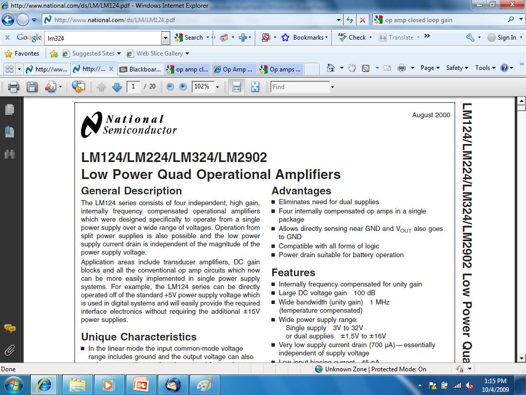
8 How to Find These Values Component Datasheets Many manufacturers have made these freely available on the internet Example: LM 324 Operational Amplifier
9
10 db Decibels Since P = V 2 /R 10 log (P/P ref ) or 20 log (V/V ref ) In this case: 20 log (V o /V in ) = 20 log (A) = 100 A = 10 5 = 100,000
11
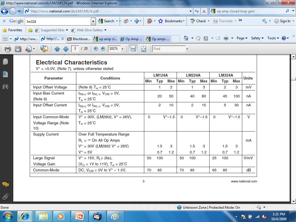
12 Large Signal Voltage Gain = A Typical A = 100 V/mV = 100V/0.001V = 100,000 Minimum A = 25 V/mV = 25 V/0.001V = 25,000
13 Caution A is Frequency Dependent
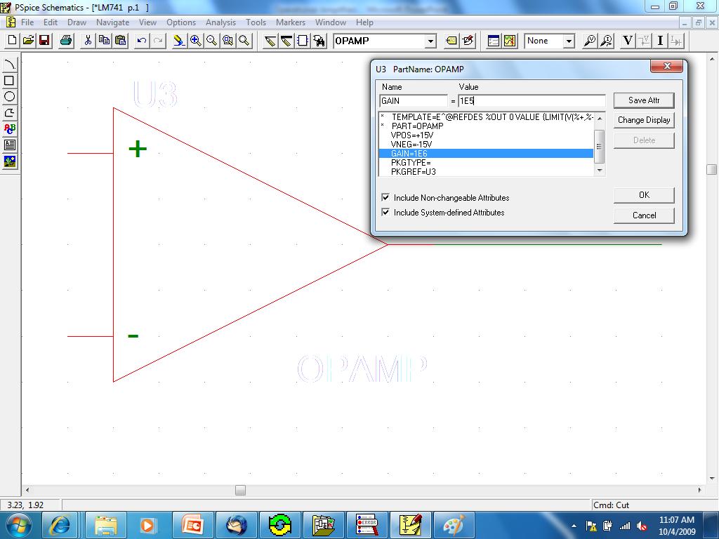
14 Modifying Gain in Pspice OpAmp Place part in a circuit Double click on component Enter a new value for the part attribute called GAIN
15 OrCAD Schematics
16 Open Circuit Output Voltage v o = A v d Ideal Op Amp v o = (v d )
17 Open Circuit Output Voltage Real Op Amp Voltage Range Output Voltage Positive Saturation A v d > V + v o ~ V + Linear Region V - < A v d < V + v o = A v d Negative A v d < V - v o ~ V - Saturation The voltage produced by the dependent voltage source inside the op amp is limited by the voltage applied to the positive and negative rails.
18 Voltage Transfer Characteristic Range where we operate the op amp as an amplifier. v d
19 Ideal Op Amp Because Ri is equal to W, the voltage across Ri is 0V. v 2 i 2 = 0 v 1 = v 2 v d = 0 V v 1 i 1 = 0
20 Almost Ideal Op Amp Ri = W Therefore, i 1 = i 2 = 0A Ro = 0 W Usually, v d = 0V so v 1 = v 2 The op amp forces the voltage at the inverting input terminal to be equal to the voltage at the noninverting input terminal if there is some component connecting the output terminal to the inverting input terminal. Rarely is the op amp limited to V - < v o < V +. The output voltage is allowed to be as positive or as negative as needed to force v d = 0V.
21 Example #1: Voltage Comparator i s = 0 i 1 = 0 i 2 = 0 Note that the inverting input and non-inverting input terminals have rotated in this schematic.
22 Example #1 (con t) The internal circuitry in the op amp tries to force the voltage at the inverting input to be equal to the noninverting input. As we will see shortly, a number of op amp circuits have a resistor between the output terminal and the inverting input terminals to allow the output voltage to influence the value of the voltage at the inverting input terminal.
23 Example #1: Voltage Comparator i s = 0 i 1 = 0 i 2 = 0 When Vs is equal to 0V, Vo = 0V. When Vs is smaller than 0V, Vo = V +. When Vs is larger than 0V, Vo = V -.
24 Electronic Response Given how an op amp functions, what do you expect Vo to be if v2 = 5V when: 1. Vs = 0V? 2. Vs = 5V? 3. Vs = 6V?
25 Example #2: Closed Loop Gain i f i s i 1 = 0 v 1 i 2 = 0 v 2
26 Example #2 (con t) i f i s i 1 i o i 2 For an almost ideal op amp, Ri = W and Ro = 0 W. The output voltage will never reach V + or V -.
27 Example #2 (con t) Virtual ground i f i s i 1 i i 2 The op amp outputs a voltage Vo such that V1 = V2.
28 Example #2 (con t) i s i 1 i f i i 2
29 Example #2: Closed Loop Gain This circuit is known as an inverting amplifier / / / 0 R R A R R V v i i i i R v R i V V v f V f s o f s f f o s S C A B
30 Types of Gain i f i s i 1 i o i i 2
31 Types of Closed Loop Gain Gain Variable Name Equation Units Voltage Gain A V v o /v s None or V/V Current Gain A I i o /i s None or A/A Transresistance Gain A R v o /i s V/A or W Transconductance Gain A G i o /v s A/V or W 1
32 Example #3: Closed Loop Gain with Real Op Amp i f i s i 1 v 1 i i 2 v 2
33 Example #3 (con t) i s = i 1 + i f i = i f - i 1 = i 2 v d = v 2 v 1 = Ri (- i 1 ) = Ri (i 2 ) V o = Av d - Ro(- i) V s = R1(i s ) v d V s = R1(i s ) + Rf(i f ) + V o V o /V s = (-R f /R1){Ab/[1 +Ab]}, where b = R1/(R1+R f )
34 Summary The output of an ideal op amp is a voltage from a dependent voltage source that attempts to force the voltage at the inverting input terminal to equal the voltage at the non-inverting input terminal. Output voltage limited to the range between V + and V -. Ideal op amp is assumed to have Ri = W and Ro = 0W. v d = 0V and the current flowing into the output terminal of the op amp is as much as required to force v 1 = v 2. Operation of an op amp was used in the analysis of voltage comparator and inverting amplifier circuits. Effect of Ri < W and Ro > 0 W was shown.
ECE2262 Electric Circuits. Chapter 4: Operational Amplifier (OP-AMP) Circuits
 Circuits") ECE2262 Electric Circuits Chapter 4: Operational Amplifier (OP-AMP) Circuits 1 4.1 Operational Amplifiers 2 4. Voltages and currents in electrical circuits may represent signals and circuits can perform
ECE2262 Electric Circuits Chapter 4: Operational Amplifier (OP-AMP) Circuits 1 4.1 Operational Amplifiers 2 4. Voltages and currents in electrical circuits may represent signals and circuits can perform
The equivalent model of a certain op amp is shown in the figure given below, where R 1 = 2.8 MΩ, R 2 = 39 Ω, and A =
 The equivalent model of a certain op amp is shown in the figure given below, where R 1 = 2.8 MΩ, R 2 = 39 Ω, and A = 10 10 4. Section Break Difficulty: Easy Learning Objective: Understand how real operational
EE100Su08 Lecture #9 (July 16 th 2008)
") EE100Su08 Lecture #9 (July 16 th 2008) Outline HW #1s and Midterm #1 returned today Midterm #1 notes HW #1 and Midterm #1 regrade deadline: Wednesday, July 23 rd 2008, 5:00 pm PST. Procedure: HW #1: Bart
EE100Su08 Lecture #9 (July 16 th 2008) Outline HW #1s and Midterm #1 returned today Midterm #1 notes HW #1 and Midterm #1 regrade deadline: Wednesday, July 23 rd 2008, 5:00 pm PST. Procedure: HW #1: Bart
Designing Information Devices and Systems I Fall 2018 Lecture Notes Note Introduction: Op-amps in Negative Feedback
 EECS 16A Designing Information Devices and Systems I Fall 2018 Lecture Notes Note 18 18.1 Introduction: Op-amps in Negative Feedback In the last note, we saw that can use an op-amp as a comparator. However,
PHYS225 Lecture 9. Electronic Circuits
 PHYS225 Lecture 9 Electronic Circuits Last lecture Field Effect Transistors Voltage controlled resistor Various FET circuits Switch Source follower Current source Similar to BJT Draws no input current
Operational Amplifiers
 Operational Amplifiers A Linear IC circuit Operational Amplifier (op-amp) An op-amp is a high-gain amplifier that has high input impedance and low output impedance. An ideal op-amp has infinite gain and
EE 321 Analog Electronics, Fall 2013 Homework #3 solution
 EE 32 Analog Electronics, Fall 203 Homework #3 solution 2.47. (a) Use superposition to show that the output of the circuit in Fig. P2.47 is given by + [ Rf v N + R f v N2 +... + R ] f v Nn R N R N2 R [
D is the voltage difference = (V + - V - ).
.") 1 Operational amplifier is one of the most common electronic building blocks used by engineers. It has two input terminals: V + and V -, and one output terminal Y. It provides a gain A, which is usually
1 Operational amplifier is one of the most common electronic building blocks used by engineers. It has two input terminals: V + and V -, and one output terminal Y. It provides a gain A, which is usually
Operational amplifiers (Op amps)
") Operational amplifiers (Op amps) Recall the basic two-port model for an amplifier. It has three components: input resistance, Ri, output resistance, Ro, and the voltage gain, A. v R o R i v d Av d v Also
Operational amplifiers (Op amps) Recall the basic two-port model for an amplifier. It has three components: input resistance, Ri, output resistance, Ro, and the voltage gain, A. v R o R i v d Av d v Also
Time Varying Circuit Analysis
 MAS.836 Sensor Systems for Interactive Environments th Distributed: Tuesday February 16, 2010 Due: Tuesday February 23, 2010 Problem Set # 2 Time Varying Circuit Analysis The purpose of this problem set
Electronics II. Midterm #2
 The University of Toledo EECS:3400 Electronics I Section sums_elct7.fm - StudentName Electronics II Midterm # Problems Points. 8. 3. 7 Total 0 Was the exam fair? yes no The University of Toledo sums_elct7.fm
Electronics II. Midterm #2
 The University of Toledo EECS:3400 Electronics I su4ms_elct7.fm Section Electronics II Midterm # Problems Points. 8. 7 3. 5 Total 0 Was the exam fair? yes no The University of Toledo su4ms_elct7.fm Problem
E40M. Op Amps. M. Horowitz, J. Plummer, R. Howe 1
 E40M Op Amps M. Horowitz, J. Plummer, R. Howe 1 Reading A&L: Chapter 15, pp. 863-866. Reader, Chapter 8 Noninverting Amp http://www.electronics-tutorials.ws/opamp/opamp_3.html Inverting Amp http://www.electronics-tutorials.ws/opamp/opamp_2.html
DESIGN MICROELECTRONICS ELCT 703 (W17) LECTURE 3: OP-AMP CMOS CIRCUIT. Dr. Eman Azab Assistant Professor Office: C
 LECTURE 3: OP-AMP CMOS CIRCUIT. Dr. Eman Azab Assistant Professor Office: C") MICROELECTRONICS ELCT 703 (W17) LECTURE 3: OP-AMP CMOS CIRCUIT DESIGN Dr. Eman Azab Assistant Professor Office: C3.315 E-mail: eman.azab@guc.edu.eg 1 TWO STAGE CMOS OP-AMP It consists of two stages: First
MICROELECTRONICS ELCT 703 (W17) LECTURE 3: OP-AMP CMOS CIRCUIT DESIGN Dr. Eman Azab Assistant Professor Office: C3.315 E-mail: eman.azab@guc.edu.eg 1 TWO STAGE CMOS OP-AMP It consists of two stages: First
320-amp-models.tex Page 1 ECE 320. Amplifier Models. ECE Linear Active Circuit Design
 320ampmodels.tex Page 1 ECE 320 Amplifier Models ECE 320 Linear Active Circuit Design 320ampmodels.tex Page 2 2Port Networks A 2port network is any circiut with two pairs of wires connecting to the outside
FEEDBACK AND STABILITY
 FEEDBCK ND STBILITY THE NEGTIVE-FEEDBCK LOOP x IN X OUT x S + x IN x OUT Σ Signal source _ β Open loop Closed loop x F Feedback network Output x S input signal x OUT x IN x F feedback signal x IN x S x
ELECTRONIC SYSTEMS. Basic operational amplifier circuits. Electronic Systems - C3 13/05/ DDC Storey 1
 Electronic Systems C3 3/05/2009 Politecnico di Torino ICT school Lesson C3 ELECTONIC SYSTEMS C OPEATIONAL AMPLIFIES C.3 Op Amp circuits» Application examples» Analysis of amplifier circuits» Single and
Homework Assignment 08
 Homework Assignment 08 Question 1 (Short Takes) Two points each unless otherwise indicated. 1. Give one phrase/sentence that describes the primary advantage of an active load. Answer: Large effective resistance
Lecture 4: Feedback and Op-Amps
 Lecture 4: Feedback and Op-Amps Last time, we discussed using transistors in small-signal amplifiers If we want a large signal, we d need to chain several of these small amplifiers together There s a problem,
Systematic methods for labeling circuits and finding a solvable set of equations, Operational Amplifiers. Kevin D. Donohue, University of Kentucky 1
 Systematic methods for labeling circuits and finding a solvable set of equations, Operational Amplifiers Kevin D. Donohue, University of Kentucky Simple circuits with single loops or node-pairs can result
Feedback Control G 1+FG A
 Introduction to Operational Amplifiers Circuit Functionality So far, only passive circuits (C, L and LC) have been analyzed in terms of the time-domain operator T and the frequency-domain operator A(ω),
Electronics II. Final Examination
 The University of Toledo f17fs_elct27.fm 1 Electronics II Final Examination Problems Points 1. 11 2. 14 3. 15 Total 40 Was the exam fair? yes no The University of Toledo f17fs_elct27.fm 2 Problem 1 11
Lecture 5: Using electronics to make measurements
 Lecture 5: Using electronics to make measurements As physicists, we re not really interested in electronics for its own sake We want to use it to measure something often, something too small to be directly
Designing Information Devices and Systems I Spring 2018 Lecture Notes Note 17
 EECS 16A Designing Information Devices and Systems I Spring 2018 Lecture Notes Note 17 17.1 Capacitive Touchscreen Viewing the physical structure corresponding to one pixel on the capacitive screen, we
Today. 1/25/11 Physics 262 Lecture 2 Filters. Active Components and Filters. Homework. Lab 2 this week
 /5/ Physics 6 Lecture Filters Today Basics: Analog versus Digital; Passive versus Active Basic concepts and types of filters Passband, Stopband, Cut-off, Slope, Knee, Decibels, and Bode plots Active Components
Chapter 10 Feedback. PART C: Stability and Compensation
 1 Chapter 10 Feedback PART C: Stability and Compensation Example: Non-inverting Amplifier We are analyzing the two circuits (nmos diff pair or pmos diff pair) to realize this symbol: either of the circuits
Bandwidth of op amps. R 1 R 2 1 k! 250 k!
 Bandwidth of op amps An experiment - connect a simple non-inverting op amp and measure the frequency response. From the ideal op amp model, we expect the amp to work at any frequency. Is that what happens?
Midterm Exam (closed book/notes) Tuesday, February 23, 2010
 Tuesday, February 23, 2010") University of California, Berkeley Spring 2010 EE 42/100 Prof. A. Niknejad Midterm Exam (closed book/notes) Tuesday, February 23, 2010 Guidelines: Closed book. You may use a calculator. Do not unstaple
University of California, Berkeley Spring 2010 EE 42/100 Prof. A. Niknejad Midterm Exam (closed book/notes) Tuesday, February 23, 2010 Guidelines: Closed book. You may use a calculator. Do not unstaple
U1 is zero based because its noninverting terminal is connected to circuit common. Therefore, the circuit reference voltage is 0 V.
 When you have completed this exercise, you will be able to operate a zener-clamped op amp comparator circuit using dc and ac voltages. You will verify your results with an oscilloscope. U1 is zero based
ECEN 325 Electronics
 ECEN 325 Electronics Operational Amplifiers Dr. Aydın İlker Karşılayan Texas A&M University Department of Electrical and Computer Engineering Opamp Terminals positive supply inverting input terminal non
Operational amplifiers (Op amps)
") Operational amplifiers (Op amps) v R o R i v i Av i v View it as an ideal amp. Take the properties to the extreme: R i, R o 0, A.?!?!?!?! v v i Av i v A Consequences: No voltage dividers at input or output.
Operational amplifiers (Op amps) v R o R i v i Av i v View it as an ideal amp. Take the properties to the extreme: R i, R o 0, A.?!?!?!?! v v i Av i v A Consequences: No voltage dividers at input or output.
Electromechanical devices MM2EMD. Lecture 5 Using Operational Amplifiers (opamps) in the real world
 in the real world") University of Nottingham Electromechanical devices MM2EMD Lecture 5 Using Operational Amplifiers (opamps) in the real world Dr. roderick.mackenzie@nottingham.ac.uk Summer 2015 @rcimackenzie Released under
University of Nottingham Electromechanical devices MM2EMD Lecture 5 Using Operational Amplifiers (opamps) in the real world Dr. roderick.mackenzie@nottingham.ac.uk Summer 2015 @rcimackenzie Released under
Linear Circuit Experiment (MAE171a) Prof: Raymond de Callafon
 Prof: Raymond de Callafon") Linear Circuit Experiment (MAE171a) Prof: Raymond de Callafon email: callafon@ucsd.edu TA: Younghee Han tel. (858) 8221763/8223457, email: y3han@ucsd.edu class information and lab handouts will be available
Linear Circuit Experiment (MAE171a) Prof: Raymond de Callafon email: callafon@ucsd.edu TA: Younghee Han tel. (858) 8221763/8223457, email: y3han@ucsd.edu class information and lab handouts will be available
Electronics II. Midterm #1
 The University of Toledo EECS:3400 Electronics I su3ms_elct7.fm Section Electronics II Midterm # Problems Points. 5. 6 3. 9 Total 0 Was the exam fair? yes no The University of Toledo su3ms_elct7.fm Problem
Lecture 5: Using electronics to make measurements
 Lecture 5: Using electronics to make measurements As physicists, we re not really interested in electronics for its own sake We want to use it to measure something often, something too small to be directly
Operational Amplifier (Op-Amp) Operational Amplifiers. OP-Amp: Components. Internal Design of LM741
 Operational Amplifiers. OP-Amp: Components. Internal Design of LM741") (Op-Amp) s Prof. Dr. M. Zahurul Haq zahurul@me.buet.ac.bd http://teacher.buet.ac.bd/zahurul/ Department of Mechanical Engineering Bangladesh University of Engineering & Technology ME 475: Mechatronics
(Op-Amp) s Prof. Dr. M. Zahurul Haq zahurul@me.buet.ac.bd http://teacher.buet.ac.bd/zahurul/ Department of Mechanical Engineering Bangladesh University of Engineering & Technology ME 475: Mechatronics
Operational Amplifiers
 NDSU Operational Amplifiers ECE 06 JSG Operational Amplifiers An operational amplifier is a input device with V o k(v V ) where k is a large number. For short, the following symbol is used for an differential
Notes on Electricity (Circuits)
") A circuit is defined to be a collection of energy-givers (batteries) and energy-takers (resistors, light bulbs, radios, etc.) that form a closed path (or complete path) through which electrical current
A circuit is defined to be a collection of energy-givers (batteries) and energy-takers (resistors, light bulbs, radios, etc.) that form a closed path (or complete path) through which electrical current
EE 230 Lecture 20. Nonlinear Op Amp Applications. The Comparator Nonlinear Analysis Methods
 EE 230 Lecture 20 Nonlinear Op Amp Applications The Comparator Nonlinear Analysis Methods Quiz 14 What is the major purpose of compensation when designing an operatinal amplifier? And the number is? 1
Electronic Circuits. Prof. Dr. Qiuting Huang Integrated Systems Laboratory
 Electronic Circuits Prof. Dr. Qiuting Huang 6. Transimpedance Amplifiers, Voltage Regulators, Logarithmic Amplifiers, Anti-Logarithmic Amplifiers Transimpedance Amplifiers Sensing an input current ii in
Nonlinear Op-amp Circuits
 deba21pratim@gmail.com Electronic Systems Group Department of Electrical Engineering IIT Bombay May 3, 2013 Overview of op-amp operating regions Linear Region Occurs when the op-amp output is stable i.e.
IMPERIAL COLLEGE OF SCIENCE, TECHNOLOGY AND MEDICINE UNIVERSITY OF LONDON DEPARTMENT OF ELECTRICAL AND ELECTRONIC ENGINEERING EXAMINATIONS 2010
 Paper Number(s): E1.1 IMPERIAL COLLEGE OF SCIENCE, TECHNOLOGY AND MEDICINE UNIVERSITY OF LONDON DEPARTMENT OF ELECTRICAL AND ELECTRONIC ENGINEERING EXAMINATIONS 2010 EEE/ISE PART I: MEng, BEng and ACGI
Unit 2: Modeling in the Frequency Domain. Unit 2, Part 4: Modeling Electrical Systems. First Example: Via DE. Resistors, Inductors, and Capacitors
 Unit 2: Modeling in the Frequency Domain Part 4: Modeling Electrical Systems Engineering 582: Control Systems I Faculty of Engineering & Applied Science Memorial University of Newfoundland January 20,
Designing Information Devices and Systems I Spring 2018 Homework 10
 EECS 16A Designing Information Devices and Systems I Spring 2018 Homework 10 This homework is due April 9, 2018, at 23:59. Self-grades are due April 12, 2018, at 23:59. Submission Format Your homework
Bipolar Junction Transistor (BJT) - Introduction
 - Introduction") Bipolar Junction Transistor (BJT) - Introduction It was found in 1948 at the Bell Telephone Laboratories. It is a three terminal device and has three semiconductor regions. It can be used in signal amplification
Bipolar Junction Transistor (BJT) - Introduction It was found in 1948 at the Bell Telephone Laboratories. It is a three terminal device and has three semiconductor regions. It can be used in signal amplification
Frequency Dependent Aspects of Op-amps
 Frequency Dependent Aspects of Op-amps Frequency dependent feedback circuits The arguments that lead to expressions describing the circuit gain of inverting and non-inverting amplifier circuits with resistive
Lecture 7: Transistors and Amplifiers
 Lecture 7: Transistors and Amplifiers Hybrid Transistor Model for small AC : The previous model for a transistor used one parameter (β, the current gain) to describe the transistor. doesn't explain many
Metal-Oxide-Semiconductor Field Effect Transistor (MOSFET)
") Metal-Oxide-Semiconductor ield Effect Transistor (MOSET) Source Gate Drain p p n- substrate - SUB MOSET is a symmetrical device in the most general case (for example, in an integrating circuit) In a separate
Metal-Oxide-Semiconductor ield Effect Transistor (MOSET) Source Gate Drain p p n- substrate - SUB MOSET is a symmetrical device in the most general case (for example, in an integrating circuit) In a separate
1/13/12 V DS. I d V GS. C ox ( = f (V GS ,V DS ,V SB = I D. + i d + I ΔV + I ΔV BS V BS. 19 January 2012
 /3/ 9 January 0 Study the linear model of MOS transistor around an operating point." MOS in saturation: V GS >V th and V S >V GS -V th " VGS vi - I d = I i d VS I d = µ n ( L V V γ Φ V Φ GS th0 F SB F
ECS 40, Fall 2008 Prof. Chang-Hasnain Test #3 Version A
 ECS 40, Fall 2008 Prof. ChangHasnain Test #3 Version A 10:10 am 11:00 am, Wednesday December 3, 2008 Total Time Allotted: 50 minutes Total Points: 100 1. This is a closed book exam. However, you are allowed
Massachusetts Institute of Technology Department of Electrical Engineering and Computer Science Electronic Circuits Fall 2000.
 Massachusetts Institute of Technology Department of Electrical Engineering and Computer Science 6.002 Electronic Circuits Fall 2000 Final Exam Please write your name in the space provided below, and circle
55:041 Electronic Circuits The University of Iowa Fall Final Exam
 Final Exam Name: Score Max: 135 Question 1 (1 point unless otherwise noted) a. What is the maximum theoretical efficiency for a class-b amplifier? Answer: 78% b. The abbreviation/term ESR is often encountered
Homework 3 Solution. Due Friday (5pm), Feb. 14, 2013
, Feb. 14, 2013") University of California, Berkeley Spring 2013 EE 42/100 Prof. K. Pister Homework 3 Solution Due Friday (5pm), Feb. 14, 2013 Please turn the homework in to the drop box located next to 125 Cory Hall (labeled
University of California, Berkeley Spring 2013 EE 42/100 Prof. K. Pister Homework 3 Solution Due Friday (5pm), Feb. 14, 2013 Please turn the homework in to the drop box located next to 125 Cory Hall (labeled
Homework 6 Solutions and Rubric
 Homework 6 Solutions and Rubric EE 140/40A 1. K-W Tube Amplifier b) Load Resistor e) Common-cathode a) Input Diff Pair f) Cathode-Follower h) Positive Feedback c) Tail Resistor g) Cc d) Av,cm = 1/ Figure
Lecture 11: J-FET and MOSFET
 ENE 311 Lecture 11: J-FET and MOSFET FETs vs. BJTs Similarities: Amplifiers Switching devices Impedance matching circuits Differences: FETs are voltage controlled devices. BJTs are current controlled devices.
Notes on Electricity (Circuits)
") A circuit is defined to be a collection of energy-givers (active elements) and energy-takers (passive elements) that form a closed path (or complete path) through which electrical current can flow. The
A circuit is defined to be a collection of energy-givers (active elements) and energy-takers (passive elements) that form a closed path (or complete path) through which electrical current can flow. The
Prof. D. Manstretta LEZIONI DI FILTRI ANALOGICI. Danilo Manstretta AA
 AA-3 LEZIONI DI FILTI ANALOGICI Danilo Manstretta AA -3 AA-3 High Order OA-C Filters H() s a s... a s a s a n s b s b s b s b n n n n... The goal of this lecture is to learn how to design high order OA-C
Introduction to Electrical and Computer Engineering. International System of Units (SI)
") Introduction to Electrical and Computer Engineering Basic Circuits and Simulation Basic Circuits and Simulation (1 of 22) International System of Units (SI) Length: meter (m) Mass: kilogram (kg) Time:
Introduction to Electrical and Computer Engineering Basic Circuits and Simulation Basic Circuits and Simulation (1 of 22) International System of Units (SI) Length: meter (m) Mass: kilogram (kg) Time:
ECE-343 Test 2: Mar 21, :00-8:00, Closed Book. Name : SOLUTION
 ECE-343 Test 2: Mar 21, 2012 6:00-8:00, Closed Book Name : SOLUTION 1. (25 pts) (a) Draw a circuit diagram for a differential amplifier designed under the following constraints: Use only BJTs. (You may
C 0 U R S E A N. Problems
 C 0 U R S E A N Problems S 0 L U T I 0 N S Introduction and Basic Concepts Note: All references to Figures and Equations whose numbers are not preceded by an "S" refer to the textbook. Following the example
EECE 2510 Circuits and Signals, Biomedical Applications Final Exam Section 3. Name:
 EECE 2510 Circuits and Signals, Biomedical Applications Final Exam Section 3 Instructions: Closed book, closed notes; Computers and cell phones are not allowed Scientific calculators are allowed Complete
Design of Analog Integrated Circuits
 Design of Analog Integrated Circuits Chapter 11: Introduction to Switched- Capacitor Circuits Textbook Chapter 13 13.1 General Considerations 13.2 Sampling Switches 13.3 Switched-Capacitor Amplifiers 13.4
Nonlinear opamp circuits
 Nonlinear opamp circuits This worksheet and all related files are licensed under the Creative Commons Attribution License, version 1.0. To view a copy of this license, visit http://creativecommons.org/licenses/by/1.0/,
Active Circuits: Life gets interesting
 Actie Circuits: Life gets interesting Actie cct elements operational amplifiers (OP AMPS) and transistors Deices which can inject power into the cct External power supply normally comes from connection
Fundamentals of Electric Circuits, Second Edition - Alexander/Sadiku
 Chapter 3, Problem 9(8). Find V x in the network shown in Fig. 3.78. Figure 3.78 Chapter 3, Solution 9(8). Consider the circuit below. 2 Ω 2 Ω -j 8 30 o I j 4 j 4 I 2 -j2v For loop, 8 30 = (2 j4)i ji 2
Notes for course EE1.1 Circuit Analysis TOPIC 10 2-PORT CIRCUITS
 Objectives: Introduction Notes for course EE1.1 Circuit Analysis 4-5 Re-examination of 1-port sub-circuits Admittance parameters for -port circuits TOPIC 1 -PORT CIRCUITS Gain and port impedance from -port
ECE 220 Laboratory 4 Volt Meter, Comparators, and Timer
 ECE 220 Laboratory 4 Volt Meter, Comparators, and Timer Michael W. Marcellin Please follow all rules, procedures and report requirements as described at the beginning of the document entitled ECE 220 Laboratory
Lecture 310 Open-Loop Comparators (3/28/10) Page 310-1
 Page 310-1") Lecture 310 Open-Loop Comparators (3/28/10) Page 310-1 LECTURE 310 OPEN-LOOP COMPARATORS LECTURE ORGANIZATION Outline Characterization of comparators Dominant pole, open-loop comparators Two-pole, open-loop
Lecture 310 Open-Loop Comparators (3/28/10) Page 310-1 LECTURE 310 OPEN-LOOP COMPARATORS LECTURE ORGANIZATION Outline Characterization of comparators Dominant pole, open-loop comparators Two-pole, open-loop
VI. Transistor amplifiers: Biasing and Small Signal Model
 VI. Transistor amplifiers: iasing and Small Signal Model 6.1 Introduction Transistor amplifiers utilizing JT or FET are similar in design and analysis. Accordingly we will discuss JT amplifiers thoroughly.
Summary Notes ALTERNATING CURRENT AND VOLTAGE
 HIGHER CIRCUIT THEORY Wheatstone Bridge Circuit Any method of measuring resistance using an ammeter or voltmeter necessarily involves some error unless the resistances of the meters themselves are taken
An Ultra Low Resistance Continuity Checker
 An Ultra Low Resistance Continuity Checker By R. G. Sparber Copyleft protects this document. 1 Some understanding of electronics is assumed. Although the title claims this is a continuity checker, its
EE 230 Lecture 21. Nonlinear Op Amp Applications. Nonlinear analysis methods Comparators with Hysteresis
 EE 230 Lecture 2 Nonlinear Op Amp Applications Nonlinear analysis methods Comparators with Hysteresis Quiz 5 Plot the transfer charactristics of the following circuit. Assume the op amp has =2 and SATL
Analog Circuits Prof. Jayanta Mukherjee Department of Electrical Engineering Indian Institute of Technology -Bombay
 Analog Circuits Prof. Jayanta Mukherjee Department of Electrical Engineering Indian Institute of Technology -Bombay Week -01 Module -05 Inverting amplifier and Non-inverting amplifier Welcome to another
EE-201 Review Exam I. 1. The voltage Vx in the circuit below is: (1) 3V (2) 2V (3) -2V (4) 1V (5) -1V (6) None of above
 3V (2) 2V (3) -2V (4) 1V (5) -1V (6) None of above") EE-201, Review Probs Test 1 page-1 Spring 98 EE-201 Review Exam I Multiple Choice (5 points each, no partial credit.) 1. The voltage Vx in the circuit below is: (1) 3V (2) 2V (3) -2V (4) 1V (5) -1V (6)
EE-201, Review Probs Test 1 page-1 Spring 98 EE-201 Review Exam I Multiple Choice (5 points each, no partial credit.) 1. The voltage Vx in the circuit below is: (1) 3V (2) 2V (3) -2V (4) 1V (5) -1V (6)
Print Name : ID : ECE Test #1 9/22/2016
 Print Name : Email ID : ECE 2660 Test #1 9/22/2016 All answers must be recorded on the answer page (page 2). You must do all questions on the exam. For Part 4 you must show all your work and write your
E2.2 Analogue Electronics
 E2.2 Analogue Electronics Instructor : Christos Papavassiliou Office, email : EE 915, c.papavas@imperial.ac.uk Lectures : Monday 2pm, room 408 (weeks 2-11) Thursday 3pm, room 509 (weeks 4-11) Problem,
ECE3050 Assignment 7
 ECE3050 Assignment 7. Sketch and label the Bode magnitude and phase plots for the transfer functions given. Use loglog scales for the magnitude plots and linear-log scales for the phase plots. On the magnitude
Active Circuits: Life gets interesting
 Actie Circuits: Life gets interesting Actie cct elements operational amplifiers (P AMPS) and transistors Deices which can inject power into the cct External power supply normally comes from connection
Chapter 18 Electric Currents
 Chapter 18 Electric Currents 1 The Electric Battery Volta discovered that electricity could be created if dissimilar metals were connected by a conductive solution called an electrolyte. This is a simple
OPERATIONAL AMPLIFIER ª Differential-input, Single-Ended (or Differential) output, DC-coupled, High-Gain amplifier
 output, DC-coupled, High-Gain amplifier") à OPERATIONAL AMPLIFIERS à OPERATIONAL AMPLIFIERS (Introduction and Properties) Phase relationships: Non-inverting input to output is 0 Inverting input to output is 180 OPERATIONAL AMPLIFIER ª Differential-input,
à OPERATIONAL AMPLIFIERS à OPERATIONAL AMPLIFIERS (Introduction and Properties) Phase relationships: Non-inverting input to output is 0 Inverting input to output is 180 OPERATIONAL AMPLIFIER ª Differential-input,
Lab 5a: Magnetic Levitation (Week 1)
") ME C134 / EE C128 Fall 2017 Lab 5a Lab 5a: Magnetic Levitation (Week 1) Magnetism, as you recall from physics class, is a powerful force that causes certain items to be attracted to refrigerators. Dave
ME C134 / EE C128 Fall 2017 Lab 5a Lab 5a: Magnetic Levitation (Week 1) Magnetism, as you recall from physics class, is a powerful force that causes certain items to be attracted to refrigerators. Dave
ECE 342 Electronic Circuits. 3. MOS Transistors
 ECE 342 Electronic Circuits 3. MOS Transistors Jose E. Schutt-Aine Electrical & Computer Engineering University of Illinois jschutt@emlab.uiuc.edu 1 NMOS Transistor Typically L = 0.1 to 3 m, W = 0.2 to
Problem Set 4 Solutions
 University of California, Berkeley Spring 212 EE 42/1 Prof. A. Niknejad Problem Set 4 Solutions Please note that these are merely suggested solutions. Many of these problems can be approached in different
Physics 364, Fall 2012, reading due your answers to by 11pm on Thursday
 Physics 364, Fall 2012, reading due 2012-09-20. Email your answers to ashmansk@hep.upenn.edu by 11pm on Thursday Course materials and schedule are at http://positron.hep.upenn.edu/p364 Assignment: This
Lecture 320 Improved Open-Loop Comparators and Latches (3/28/10) Page 320-1
 Page 320-1") Lecture 32 Improved OpenLoop Comparators and es (3/28/1) Page 321 LECTURE 32 IMPROVED OPENLOOP COMPARATORS AND LATCHES LECTURE ORGANIZATION Outline Autozeroing Hysteresis Simple es Summary CMOS Analog
Lecture 32 Improved OpenLoop Comparators and es (3/28/1) Page 321 LECTURE 32 IMPROVED OPENLOOP COMPARATORS AND LATCHES LECTURE ORGANIZATION Outline Autozeroing Hysteresis Simple es Summary CMOS Analog
Final Exam. 55:041 Electronic Circuits. The University of Iowa. Fall 2013.
 Final Exam Name: Max: 130 Points Question 1 In the circuit shown, the op-amp is ideal, except for an input bias current I b = 1 na. Further, R F = 10K, R 1 = 100 Ω and C = 1 μf. The switch is opened at
Engineering Fundamentals and Problem Solving, 6e
 Engineering Fundamentals and Problem Solving, 6e Chapter 17 Electrical Circuits Chapter Objectives Compute the equivalent resistance of resistors in series and in parallel Apply Ohm s law to a resistive
I. Frequency Response of Voltage Amplifiers
 I. Frequency Response of Voltage Amplifiers A. Common-Emitter Amplifier: V i SUP i OUT R S V BIAS R L v OUT V Operating Point analysis: 0, R s 0, r o --->, r oc --->, R L ---> Find V BIAS such that I C
Prepare for this experiment!
 Notes on Experiment #10 Prepare for this experiment! Read the P-Amp Tutorial before going on with this experiment. For any Ideal p Amp with negative feedback you may assume: V - = V + (But not necessarily
ECE-342 Test 3: Nov 30, :00-8:00, Closed Book. Name : Solution
 ECE-342 Test 3: Nov 30, 2010 6:00-8:00, Closed Book Name : Solution All solutions must provide units as appropriate. Unless otherwise stated, assume T = 300 K. 1. (25 pts) Consider the amplifier shown
Analog Computing Technique
 Analog Computing Technique by obert Paz Chapter Programming Principles and Techniques. Analog Computers and Simulation An analog computer can be used to solve various types o problems. It solves them in
Chapter 2 Circuit Elements
 Chapter 2 Circuit Elements 2.1 Voltage and Current Sources 2.2 Electrical Resistance (Ohm s Law) 2.3 Construction of a Circuit Model 2.4 Kirchhoff s Laws 2.5 Analysis of a Circuit Containing Dependent
Chapter 2. Engr228 Circuit Analysis. Dr Curtis Nelson
 Chapter 2 Engr228 Circuit Analysis Dr Curtis Nelson Chapter 2 Objectives Understand symbols and behavior of the following circuit elements: Independent voltage and current sources; Dependent voltage and
Electronics. Basics & Applications. group talk Daniel Biesinger
 Electronics Basics & Applications group talk 23.7.2010 by Daniel Biesinger 1 2 Contents Contents Basics Simple applications Equivalent circuit Impedance & Reactance More advanced applications - RC circuits
EE 435. Lecture 2: Basic Op Amp Design. - Single Stage Low Gain Op Amps
 EE 435 ecture 2: Basic Op Amp Design - Single Stage ow Gain Op Amps 1 Review from last lecture: How does an amplifier differ from an operational amplifier?? Op Amp Amplifier Amplifier used in open-loop
Homework assignment from , MEMS Capacitors lecture
 Homework assignment from 05-02-2006, MEMS Capacitors lecture 1. Calculate the capacitance for a round plate of 100µm diameter with an air gap space of 2.0 µm. C = e r e 0 * A/d (1) e 0 = 8.85E-12 F/m e
MAS.836 PROBLEM SET THREE
 MAS.836 PROBLEM SET THREE FSR, Strain Gauge, and Piezo Circuits: The purpose of this problem set is to familiarize yourself with the most common forms of pressure and force measurement. The circuits you
Series & Parallel Resistors 3/17/2015 1
 Series & Parallel Resistors 3/17/2015 1 Series Resistors & Voltage Division Consider the single-loop circuit as shown in figure. The two resistors are in series, since the same current i flows in both
INTRODUCTION TO ELECTRONICS
 INTRODUCTION TO ELECTRONICS Basic Quantities Voltage (symbol V) is the measure of electrical potential difference. It is measured in units of Volts, abbreviated V. The example below shows several ways
Lecture 7, ATIK. Continuous-time filters 2 Discrete-time filters
 Lecture 7, ATIK Continuous-time filters 2 Discrete-time filters What did we do last time? Switched capacitor circuits with nonideal effects in mind What should we look out for? What is the impact on system