General Explanation Ⅲ 1 Ⅲ 2
|
|
|
- Coleen James
- 6 years ago
- Views:
Transcription

1 General Explanation 1 2
2 Selection Procedure Selection of Linear Way and Linear Roller Way should be considered from the most important required matter to details in order. Typical procedure is shown below. Example of Linear Way and Linear Roller Way selection procedure Check for use condition Machines and locations in use Confirm requirements, performance, and special environments of Linear Way and Linear Roller Way. Selection of Linear Way and Linear Roller Way model Select a suitable Linear Way and Linear Roller Way model for usage conditions in consideration of an applied load, a load direction, rigidity, friction, ease of mounting, etc. See pages 7 to 8 and descriptions of each series. Selection of interchangeable or non-interchangeable specification Take maintainability and ease of assembly into account. See pages 15 to 18 and descriptions of each series. Selection of accuracy class Select based on required traveling accuracy. Select a higher accuracy class especially when traveling accuracy is important. See descriptions of each series. Temporary specification of size and numbers of sets and slide units Take a balance of machines / equipment and past experience into account. Calculation of applied load Calculate an applied load on each slide unit of Linear Way and Linear Roller Way. Consider loads and fluctuating loads by acceleration and deceleration. See pages 9 to 18. Calculation of static safety factor Calculate a static safety factor to confirm suitability for usage conditions. See page 6. Calculation of life Calculate rating life to confirm suitability for use conditions. See page 6. Consideration of preload amount or clearance Select a suitable preload amount or clearance for use conditions. See page 20 and descriptions of each series. Determination of size, numbers of sets and slide units, and preload Selection of lubrication and dust protection Select oil lubrication or grease lubrication. Select dust protection such as seals and bellows according to environmental conditions. See page 21 and descriptions of each series. Consideration of surroundings Consider a mounting method and related dimensions. See page 36 and descriptions of each series. Final specification determination of Linear Way, Linear Roller Way and their surroundings 3 4
3 Load Rating and Life Life of linear motion rolling guides Basic dynamic load rating C Calculating formula of life Static safety factor Even in normal operational status, a linear motion rolling guide will reach the end of its life after a certain period of operations. As repeated load is constantly applied onto a raceway and rolling elements of the linear motion rolling guide, this leads to leprous damage (scale-like wear fragments) called fatigue flaking due to rolling contact fatigue of materials, it will be unusable at the end. Total traveling distance before occurrence of this fatigue flaking on a raceway or rolling elements is called the life of linear motion rolling guide. As the life of linear motion rolling guide may vary depending on material fatigue phenomenon, rating life based on statistic calculation is used. Rating life Complying with ISO Basic dynamic load rating refers to load with certain direction and size that is logically endurable for rating life of m when a group of the same linear motion rolling guides is operated individually under the same conditions. Basic static load rating C 0 Complying with ISO Basic static load rating refers to static load generating a certain contact stress at the center of contact part of the rolling elements and a raceway under maximum load, which is the load at the allowable limit for normal rolling motion. Generally, it is used considering static safety factor. The rating life calculation formulas are shown below. Linear Way L50( C P ) 3 (1) Linear Roller Way L50( C P ) 10/3 (2) where, L: Rating life, 10 3 m C: Basic dynamic load rating, N P: Dynamic equivalent load, N Life time can be calculated by applying a stroke length and a number of strokes per minute to the formula below. L h 106 L 2Sn 1 60 (3) Generally, basic static load rating and static moment rating is considered as load at the allowable limit for normal rolling motion. However, static safety factor must be considered according to operating conditions and required performance of the linear motion rolling guide. Static safety factor can be obtained by the following equation and typical values are indicated in Tables 2.1 and 2.2. Equation (6) is a representative equation for a moment load. Moment load and static moment rating in each direction is applied for the calculation. f S C 0 P (5) 0 f S T 0 M (6) 0 Rating life of linear motion rolling guide refers to the total traveling distance 90% of a group of the same linear motion rolling guide can operate without linear motion rolling guide material damages due to rolling contact fatigue when they are operated individually under the same conditions. C, C0 Fig. 1 Direction of load rating Static moment rating T 0, T X, T Y Static moment rating refers to static moment load generating a certain contact stress at the center of contact parts of rolling elements and a raceway under the maximum load when the moment load shown in Fig. 2 is loaded, which is the moment load at the allowable limit for normal rolling motion. Generally, it is used considering static safety factor. where, L h : Rating life in hours, h S : Stroke length, mm n 1 : Number of strokes per minute, cpm Load factor Load applied to a linear motion rolling guide can be larger than theoretical load due to machine vibration or shock. Generally, the applied load is obtained by multiplying it by the load factor indicated in Table 1. Table 1 Load factor Operating conditions Smooth operation free from shock Normal operation Operation with shock load f W where, f S : Static safety factor C 0 : Basic static load rating, N P 0 : Static equivalent load, N T 0 : Static moment rating, Nm M 0 : Moment load in each direction, Nm (maximum moment load) Table 2.1 Static safety factor for Linear Way Operational conditions Operation with vibration and / or shock 3 5 High operating performance 2 4 Normal operating conditions 1 3 Table 2.2 Static safety factor for Linear Roller Way Operational conditions Operation with vibration and / or shock 4 6 High operating performance 3 5 Normal operating conditions f s f s T 0 T X T Y Fig. 2 Direction of static moment rating 5 6
4 Load Rating and Life Dynamic equivalent load Table 3 Conversion factor for load direction Static equivalent load Table 5 Conversion factor for load direction When a load is applied in a direction other than that of the basic dynamic load rating or a complex load is applied, the dynamic equivalent load must be calculated to obtain the basic rating life. F r F a F a F r When a load is applied in a direction other than that of the basic static load rating or a complex load is applied, the static equivalent load must be calculated to obtain the static safety factor. F r F a F a F r Obtain the downward and lateral conversion loads from the loads and moments in various directions. F re k r F r C 0 T0 M 0 C 0 TX M X (7) F ae k a F a C 0 T M Y (8) Y where, F re : Downward conversion load, N F ae : Lateral conversion load, N F r : Downward load, N F a : Lateral load, N M 0 : Moment load in the T 0 direction, Nm M X : Moment load in the T X direction, Nm M Y : Moment load in the T Y direction, Nm k r, k a : Conversion factors for load direction (See Table 3) C 0 : Basic static load rating, N T 0 : Static moment rating in the T 0 direction, Nm T X : Static moment rating in the T X direction, Nm T Y : Static moment rating in the T Y direction, Nm Linear Way and Linear Roller Way Conversion factor Series name and size k r Fr 0 F r 0 ka C-Lube Linear Way ML Ball retained type Linear Way L Ball non-retained type C-Lube Linear Way MLV C-Lube Linear Way MV C-Lube Linear Way ME Linear Way E Low Decibel Linear Way E C-Lube Linear Way MH Linear Way H Linear Way H Horizontal mounting type Linear Way F C-Lube Linear Way MUL Linear Way U LWFH , C-Lube Linear Roller Way Super MX Linear Roller Way Super X Linear Roller Way X LWLM Linear Way Module LWM LRWM Note 1 The upper value of k a columns represents the right direction and the lower value represents the left direction. F r Linear Way Module Linear Way H Side mounting type F a P 0 k 0r F r k 0a F a C 0 T0 M 0 C 0 TX M X C 0 T M Y (10) Y where, P 0 : Static equivalent load, N F r : Downward load, N F a : Lateral load, N M 0 : Moment load in the T 0 direction, Nm M X : Moment load in the T X direction, Nm M Y : Moment load in the T Y direction, Nm k 0r, k 0a : Conversion factors for load direction (See Table 5) C 0 : Basic static load rating, N T 0 : Static moment rating in the T 0 direction, Nm T X : Static moment rating in the T X direction, Nm T Y : Static moment rating in the T Y direction, Nm Linear Way and Linear Roller Way Conversion factor Series name and size k 0r F r 0 F r 0 k0a C-Lube Linear Way ML Ball retained type Linear Way L Ball non-retained type C-Lube Linear Way MLV C-Lube Linear Way MV C-Lube Linear Way ME Linear Way E Low Decibel Linear Way E C-Lube Linear Way MH Linear Way H Linear Way H Horizontal mounting type Linear Way F C-Lube Linear Way MUL Linear Way U LWFH , C-Lube Linear Roller Way Super MX Linear Roller Way Super X Linear Roller Way X LWLM Linear Way Module LWM LRWM Note 1 The upper value of k 0a columns represents the right direction and the lower value represents the left direction. F r Linear Way Module Linear Way H Side mounting type F a Obtain the dynamic equivalent load from the downward and lateral conversion loads. PXF re YF ae (9) where, P : Dynamic equivalent load, N X, Y : Dynamic equivalent load factor (See Table 4) F re : Downward conversion load, N F ae : Lateral conversion load, N Table 4 Dynamic equivalent load factor Class X Y F re F ae F re F ae
5 Calculated Load Examples of calculation for the loads applied to Linear Way and Linear Roller Way that is incorporated in machine / equipment is shown in Table 6.1 to Table 6.6. Table 6.1 One track rail and one slide unit Y Table 6.3 Two track rails and one slide unit 1 Y M y Load positionx, Y, Z M y F X 1 0 Z 0 M p Load positionx, Y, Z F Y X X M r F Y 0 Z F Z Load positionx, Y, Z Y Drive positiony d, Z d L L2 L2 2 Z F x F Y 0 X M p 0 X 2 0 Z M r F Y F Z Load positionx, Y, Z 1 Y Drive positiony d, Z d Slide unit No. Downward load F r Lateral load F a Load applied on the slide unit Moment load in the T 0 direction M 0 Moment load in the T X direction M X Moment load in the T Y direction M Y 1 F z F Y M r M p M y Remark: The moment loads in each direction M r, M p, M y can be obtained by the following equation. M r F Y ZF Z Y M p F X ZZ d F Z X M y F X YY d F Y X Slide unit No. 1 2 Downward load F r F z 2 M r L F z 2 M r L Load applied on the slide unit Lateral load F a Remark: The moment loads in each direction M r, M p, M y can be obtained by the following equation. M r F Y ZF Z Y M p F X ZZ d F Z X M y F X YY d F Y X F 2 Y F 2 Y Moment load in the T X direction M X M 2 p M 2 p Moment load in the T Y direction M Y M 2 y M 2 y Table 6.2 One track rail and two slide units Y M y Load positionx, Y, Z F x 2 1 F Y 0 X l2 l l2 Z M r Z F Z M p F Y Load positionx, Y, Z X 0 Y Drive positiony d, Z d Slide unit No. Downward load F r Load applied on the slide unit Lateral load F a Moment load in the T 0 direction M 0 1 F z 2 M p l F Y 2 M y l M 2 r 2 F z 2 M p l F Y 2 M y l M 2 r Remark: The moment loads in each direction M r, M p, M y can be obtained by the following equation. M r F Y ZF Z Y M p F X ZZ d F Z X M y F X YY d F Y X 9 10
6 Calculated Load Table 6.4 Two track rails and two slide units Table 6.5 Two track rails and three slide units Y M y Load positionx, Y, Z Y M y Load positionx, Y, Z L L2 L2 0 F x 4 3 F Y X L L2 L2 F x F Y X l2 l l2 Z M r l2 l l2 Z M r Z M p 3,4 F Y F Z Load positionx, Y, Z 1,2 Z M p 4,5,6 F Y F Z Load positionx, Y, Z 1,2,3 0 2,4 1,3 X 0 Y Drive positiony d, Z d 0 X 3,6 2,5 1,4 0 Y Drive positiony d, Z d Slide unit No. Downward load F r Load applied on the slide unit Lateral load F a Slide unit No. Downward load F r Load applied on the slide unit Lateral load F a 1 F z 4 M r 2L M p 2l F Y 4 M y 2l 1 F z 6 M r 3L M p 2l F Y 6 M y 2l 2 F z 4 M r 2L M p 2l F Y 4 M y 2l 2 F z 6 M r 3L F 6 Y 3 F z 4 M r 2L M p 2l F Y 4 M y 2l 3 F z 6 M r 3L M p 2l F Y 6 M y 2l 4 F z 4 M r 2L M p 2l F Y 4 M y 2l 4 F z 6 M r 3L M p 2l F Y 6 M y 2l Remark: The moment loads in each direction M r, M p, M y can be obtained by the following equation. M r F Y ZF Z Y M p F X ZZ d F Z X M y F X YY d F Y X 5 6 F z 6 M r 3l F z 6 M r 3L M p 2l Remark: The moment loads in each direction M r, M p, M y can be obtained by the following equation. M r F Y ZF Z Y M p F X ZZ d F Z X M y F X YY d F Y X F 6 Y F Y 6 M y 2l 11 12
7 Calculated Load Table 6.6 Two track rails and four slide units L L2 L2 Y M y F x Load positionx, Y, Z 1 F Y X 5 Mean Equivalent Load for Fluctuating Load When the load on the Linear Way and Linear Roller Way varies, instead of dynamic equivalent load P, the mean equivalent load P m is used for calculating formula of life. The mean equivalent load is a load converted to give life equal to that for fluctuating load. It is obtained by the following formula: p P m 1 L p P n dl (11) L 0 l2 l2l2 l l l2 Z M r where, P m : Mean equivalent load, N L : Total traveling distance, m P n : Fluctuating load, N p : Exponent (ball type: 3, roller type: 10/3) Z M p 5,6,7,8 F Y F Z Load positionx, Y, Z 1,2,3,4 Table 7 gives calculation examples of the mean equivalent load for typical fluctuating loads. 0 X 4,8 3,7 2,6 1,5 0 Y Drive position Y d, Z d Table 7 Mean equivalent load for fluctuating load Example Mean equivalent load Slide unit No. 1 2 Downward load F r F z 8 M r 4L M p 2 F z 8 M r 4L M p 2 l l 2 l 2 l l 2 l 2 Load applied on the slide unit Lateral load F a F M 8 Y y l 2 l 2 l 2 F M 8 Y y l 2 l 2 l 2 Stepwise changing load P L 1 P 1 P 2 L 2 L P n L n P m P m = p 1 L P p 1 L 1 +P p 2 L 2 + +P p n L n where, L 1 : Total traveling distance receiving the load P 1, m L 2 : Total traveling distance receiving the load P 2, m L n : Total traveling distance receiving the load P n, m F z 8 M r 4L M p 2 F z 8 M r 4L M p 2 F z 8 M r 4L M p 2 l l 2 l 2 l l 2 l 2 l l 2 l 2 F M 8 Y y l 2 l 2 l 2 F M 8 Y y l 2 l 2 l 2 F M 8 Y y l 2 l 2 l 2 Monotonously changing load P P min L P max P m P m 1 3 2P max +P min where, P max : Maximum value of fluctuating load, N P min : Minimum value of fluctuating load, N 6 F z 8 M r 4L M p 2 l l 2 l 2 F M 8 Y y l 2 l 2 l 2 7 F z 8 M r 4L M p 2 l l 2 l 2 F M 8 Y y l 2 l 2 l 2 8 F z 8 M r 4L M p 2 l l 2 l 2 F M 8 Y y l 2 l 2 l 2 Remark: The moment loads in each direction M r, M p, M y can be obtained by the following equation. M r F Y ZF Z Y M p F X ZZ d F Z X M y F X YY d F Y X 13 14
8 Examples of Load and Life Calculation Example 1 Linear Way Model ME 25 C2 R640 H Work mass m 2 10 kg Basic dynamic load Position of center of rating C N gravity of work X 3 75 mm Basic static load rating C N Y 3 Z 3 80 mm 68 mm Applied load F X N Number of strokes per F Y N minute n 1 5 cpm F Z N Stroke length S 100 mm Load position X 1 60 mm Distance between Y 1 50 mm slide units l 100 mm Z 1 83 mm Distance between the Table mass m 1 10 kg track rails L 150 mm Position of the center of gravity of table X 2 0 mm Drive position Y d Z d 150 mm 10 mm Y 2 0 mm Z 2 43 mm Position of the center of gravity of table X 2, Y 2, Z 2 Unit 3, 4 L2 0 L Z F Y F Z m 1 g Load positionx 1, Y 1, Z 1 m 2 g Position of the center of gravity of work X 3, Y 3, Z 3 Unit 1, 2 Y Drive positiony d, Z d L2 Unit 2, 4 l2 0 l Z F X m 1 g l2 F Z m 2 g X Unit 1, 3 The life and static safety factor in the case of Example 1 is calculated. Load factor f W is assumed to be 1.5. Calculation of load on the slide unit Due to the applied load and the table weight, moment load occurs around each coordinate axis of the Linear Way as shown below. M r F Y ZF Z YF Y1 Z 1 F Z1 Y 1 m 1 gy 2 m 2 gy M p F X ZZ d F Z XF X1 Z 1 Z d F Z1 X 1 m 1 gx 2 m 2 gx M y F X YY d F Y XF X1 Y 1 Y d F Y1 X where, M r : Moment load in the rolling direction, Nmm M p : Moment load in the pitching direction, Nmm M y : Moment load in the yawing direction, Nmm The loads applied on each slide unit are calculated according to Table 6.4 on page 11. F r1 F Z M r M p 4 2L M r M p 2L 2 l F r2 F Z M r M p 4 2L F r3 F Z M r M p 4 2L F r4 F Z M r M p 4 2L 1150 F m gm Z1 1 2 g 2 l 4 F m gm Z1 1 2 g 2 l 4 F m gm Z1 1 2 g 2 l 4 F m gm Z1 1 2 g 2 l 4 F a1 F a3 F Y M y 4 2 F Y1 M y l 4 2 l F a2 F a4 F Y M y F Y1 M y 4 2 l 4 2 l 600 M r M p 2L 2 l 346 M r M p 2L 2 l 252 M r M p 2L 2 l Calculating of rating life The upward / downward load and lateral load are converted by formula (7) and (8) on page 7. F re1 k r F r F re2 k r F r F re3 k r F r F re4 k r F r F ae1 k a F a F ae2 k a F a F ae3 k a F a F ae4 k a F a where, k r, k a : Conversion factors for load direction (See Table 3 on page 7.) The dynamic equivalent load is calculated by formula (9) on page 7. P 1 XF re1 YF ae P 2 XF re2 YF ae P 3 XF re3 YF ae P 4 XF re4 YF ae The basic rating life of slide unit 1 receiving the largest dynamic equivalent load is calculated. The basic rating life is obtained by the formula (1) given on the page 6 considering the load factor f w (see Table 1 on page 6). C L 50 1 ( fw P 1 ) 3 50 ( ) L h1 106 L 2S n As the result of calculation above, the basic rating life is about 73,500 hours. Calculating of static safety factor The static equivalent load is calculated from the upward / downward load and lateral load by formula (10) on page 8. P 01 k 0r F r1 k 0a F a P 02 k 0r F r2 k 0a F a P 03 k 0r F r3 k 0a F a P 04 k 0r F r4 k 0a F a where, k 0r, k 0a : Conversion factors for load direction (See Table 5 on page 8.) The static safety factor of slide unit 1 receiving the largest static equivalent load is calculated. The static safety factor is calculated by formula (5) on page 6. f s1 C P As the result of calculation above, the static safety factor is about
9 Examples of Load and Life Calculation Example 2 Linear Way Model MH 45 C2 R1050 H Distance between slide units l 200 mm Basic dynamic load rating C N Stroke length S 500 mm Basic static load rating C N Number of strokes per minute n 1 6 cpm Static moment rating in the T 0 direction T Nm Maximum traveling velocity V 100 mm/s Table mass m kg Time spent for acceleration t s Position of the center of gravity of table X 1 50 mm Time spent during constant speed motion t s Y 1 0 mm Time spent for deceleration t s Z 1 80 mm Drive position Y d 60 mm Work mass m kg Z d 20 mm Position of center of gravity of work X mm Y 2 10 mm Z mm The life and static safety factor in the case of Example 2 is calculated. Load factor f W is assumed to be 1.5. Calculation of load on the slide unit Due to the applied load and the table mass and inertia force, moment load occurs around each coordinate axis of the Linear Way as shown below. During acceleration at the start of motion M r F Y ZF Z Ym 1 gy 1 m 2 gy M p F X ZZ d F Z X V max m t1 Z 1 Z d m 1000t1 2 Z 2 Z d m 1 gx 1 m 2 gx 2 V max Velocity mm/s M y F X YY d F Y X V max 0 Z m 2 g m 1 g Position of center of gravity of work X 2, Y 2, Z 2 Position of the center of gravity of table X 1, Y 1, Z 1 Y Unit 2 Drive position Y d, Z d t 1 t 2 t 3 Time S V max m 1000t1 1 Y 1 Y d m 1000t1 2 Y 2 Y d Stroke length l2 0 l Z l2 During constant speed motion M r m 1 gy 1 m 2 gy M p m 1 gx 1 m 2 gx M y 0 Inertia force of the table During deceleration at the end of motion M r m 1 gy 1 m 2 gy V max M p m t3 Z 1 Z d m 1000t3 2 Z 2 Z d m 1 gx 1 m 2 gx V max Unit 1 Inertia force of the work V max V max M y m 1000t3 1 Y 1 Y d m 1000t3 2 Y 2 Y d where, M r : Moment load in the rolling direction, Nmm M p : Moment load in the pitching direction, Nmm M y : Moment load in the yawing direction, Nmm X The loads applied on each slide unit are calculated according to Table 6.2 on page 9. During acceleration at the start of motion F r1 F Z M p 2 m gm 1 2 g M p l 2 l F r2 F Z M p 2 m gm 1 2 g M p l 2 l 5460 F a1 F Y M y 2 l 280 F a2 F Y M y 2 l 280 M 01 M 02 M r During constant speed motion F r F r F a1 F a2 0 M 01 M During deceleration at the end of motion F r F r F a1 280 F a2 280 M 01 M Calculating of rating life The upward / downward load, lateral load and the moment load along T 0 direction are calculated by the formula (7) and (8) on page 7, and the dynamic equivalent load is calculated by formula (9). During acceleration at the start of motion F re1 k r F r1 C 0 M T F re F ae1 k a F a F ae P 1a X F re1 Y F ae P 2a X F re2 Y F ae During constant speed motion F re F re F ae1 0 F ae2 0 P 1b P 2b 7100 During deceleration at the end of motion F re F re Because the dynamic equivalent load changes stepwise along the traveling distance, the mean equivalent load is calculated from in Table 7 on page 14. P 3 1 V max t V max t 3 m1 ( P 1 S 1a 3 P 2 1b3 V max t 2 P 1c ) 3 2 { 1 ( { 1 ( P m )} 1/ )} 1/ The basic rating life of slide unit 1 receiving the largest dynamic equivalent load is calculated. The basic rating life is obtained by the formula (1) given on the page 6 considering the load factor f w (see Table 1 on page 6). L 50 1 ( C fw P m1 ) 3 50 ( ) L h1 106 L 2S n As the result of calculation above, the basic rating life is about 3,030 hours. Calculating of static safety factor The static equivalent load is calculated from the upward / downward load and lateral load by formula (10) on page 8. During acceleration at the start of motion P 01a k 0r F r1 k 0a F a1 C 0 M T P 02a k 0r F r2 k 0a F a2 C 0 M T During constant speed motion P 01b P 02b During deceleration at the end of motion P 01c P 02c The static safety factor of slide unit 1 during acceleration at the start of motion receiving the largest static equivalent load is calculated. The static safety factor is calculated by formula (5) on page 6. f s C P01a As the result of calculation above, the static safety factor is about F ae F ae P 1c P 2c
10 Accuracy Five classes of accuracy, ordinary, high, precision, super precision, and ultra precision are specified for Linear Way and Linear Roller Way. Table 8 Accuracy classes and series Series name C-Lube Linear Way ML Linear Way L Class classification symbol The outline of applicable accuracy classes is shown in Table 8. For details, see an explanation of each series. Ordinary High Precision Super precision Ultra precision No symbol H P SP UP C-Lube Linear Way MLV C-Lube Linear Way MV C-Lube Linear Way ME Linear Way E C-Lube Linear Way MH Linear Way H Linear Way F C-Lube Linear Way MUL Linear Way U C-Lube Linear Roller Way Super MX Linear Roller Way Super X Linear Roller Way X Linear Way Module Preload Objectives of preload In some cases, the linear motion rolling guide is used with clearance given to the linear motion rolling guide when light motion with small load is required. However, for some applications, it may be used with play in the guiding mechanism removed or with preload to increase rigidity. Preload is applied to the contact parts of a raceway and rolling elements with internal stress generated in advance. When a external load is applied on the preloaded linear motion rolling guide, shock absorbing with this internal stress makes elastic deformation smaller, and its rigidity is increased. (See Fig. 3) Preload setting Preload amount is determined by considering the characteristics of the machines or equipments on which the linear motion rolling guide is mounted and the nature of load acting on the linear motion rolling guide. The standard amount of preload for linear motion rolling guides is, in general, approx. 1/3 of load when the rolling elements are balls (steel balls) and approx. 1/2 of load when they are rollers (cylindrical rollers). If the linear motion rolling guides are required to have very high rigidity to withstand vibration or fluctuating load, a larger preload may be applied. For applicable preload amount, see Table 9. For details, see an explanation of each series. Precaution for preload selection Even when high rigidity must be required, excessive preload should be avoided, because it will produce an excessive stress between rolling elements and raceways, and eventually result in short life of linear motion rolling guides. It is important to apply a proper amount of preload, considering the operational conditions. When using with a large preload, contact. Table 9 Series and preload amount Series name C-Lube Linear Way ML Linear Way L Preload preload symbol Elastic deformation μm Ball diameter 10 mm Diameter and length of roller 10 mm10 mm Preload amount: Equivalent to 0.05C 0 Ball without preload Ballwith preload Roller without preload Roller with preload Load N Fig. 3 Preload and elastic deformation behavior Clearance Clearance Standard Light preload Medium preload Heavy preload TC T0 No symbol T1 T2 T3 C-Lube Linear Way MLV 1 C-Lube Linear Way MV C-Lube Linear Way ME Linear Way E C-Lube Linear Way MH Linear Way H Linear Way F C-Lube Linear Way MUL Linear Way U C-Lube Linear Roller Way Super MX Linear Roller Way Super X Linear Roller Way X Note 1 Preload is adjusted to have subtle clearance or minimal amount of preload
11 Friction Lubrication Friction of linear motion rolling guide Objectives of lubrication Grease replenishment interval Mixing of different type of grease The static friction (start-up friction) of linear motion rolling guides is much lower than that of conventional plain guides. Also, the difference between static friction and dynamic friction is small, and frictional resistance varies little when velocity changes. These are excellent features of linear motion rolling guides, and account for their ability to reduce power consumption, suppress operating temperature rise, and increase traveling speed. Since frictional resistance and variation are small, highspeed response characteristics to motion commands and high accuracy positioning can be achieved. Friction coefficient The frictional resistance of linear motion rolling guides varies with their model, applied load, velocity and characteristics of lubricant. Generally, lubricant or seals are major factors in determining the frictional resistance in light load or highspeed operation, while the amount of load is the major factor in heavy load or low speed operation. The frictional resistance of linear motion rolling guides depends on various factors, but generally the following formula is used. FP (11) where, F : Frictional resistance, N : Dynamic friction coefficient P : Applied load, N For sealed guides, seal resistance is added to the above value, but this resistance varies greatly depending on the interference amount of seal lip and lubrication conditions. Where the lubrication and mounting condition are correct and the load is moderate, the friction coefficients of Linear Way and Linear Roller Way in operation are within the range shown in Table 10. Generally, friction coefficient is large under small load. Table 10 Friction coefficient 21 Series name Linear Way Linear Roller Way Dynamic friction coefficient Note 1 These friction coefficients do not include seal. The objectives of applying lubricant for linear motion rolling guides is to keep raceways, rolling elements, etc. in a linear motion rolling guide from metal contact, and thereby reduce friction and wear preventing heat generation and seizure. When an adequate oil film is formed at the rolling contact area between the raceways and rolling elements, the contact stress due to load can be reduced. To manage the formation of adequate oil film is important for ensuring the reliability of linear motion rolling mechanism. Selection of lubricant To obtain the full performance of linear motion rolling guides, it is necessary to select an appropriate lubricant and lubrication method by considering the model, load and velocity of each linear motion rolling guide. However, as compared with plain guides, lubrication of linear motion rolling guides is much simpler. Only a small amount of lubrication oil is needed and replenishment interval is longer, so maintenance can be greatly reduced. Grease and oil are the two most commonly used lubricants for linear motion rolling guides. Grease lubrication For linear motion rolling guides, lithium-soap base grease (Consistency No.2 of JIS) is commonly used. For rolling guides operating under heavy load conditions, grease containing extreme pressure additives is recommended. In clean and high-vacuum environments, where low dust generating performance and low vaporization characteristics are required, greases containing a synthetic-base oil or a soap other than the lithium-soap base are used. For applications in these environments, due consideration is necessary to select a grease that is suitable for the operating conditions of linear motion rolling guide and achieves satisfactory lubrication performance at the same time. Table 11 Pre-packed grease list Series name C-Lube Linear Way ML Linear Way L C-Lube Linear Way MLV C-Lube Linear Way MV C-Lube Linear Way ME Linear Way E C-Lube Linear Way MH 1 Linear Way H 1 Linear Way F C-Lube Linear Way MUL Linear Way U 2 Pre-packed grease MULTEMP PS No.2 [KYODO YUSHI CO., LTD.] Alvania EP Grease 2 [SHOWA SHELL SEKIYU K. K.] MULTEMP PS No.2 [KYODO YUSHI CO., LTD.] C-Lube Linear Roller Way Super MX Linear Roller Way Super X Alvania EP Grease 2 Linear Roller Way X [SHOWA SHELL SEKIYU K. K.] Linear Way Module Notes 1 MULTEMP PS No.2 is pre-packed in size 8 to 12 series. 2 Alvania EP Grease 2 is pre-packed in size 40 to 130 series. The quality of any grease will gradually deteriorate as operating time passes. Therefore, periodic replenishment is necessary. Grease replenishment interval varies depending on the operating conditions. A six month interval is generally recommended, and if the machine operation consists of reciprocating motions with many cycles and long strokes, replenishment every three month is recommended. In addition, linear motion rolling guides in which the lubrication part "C-Lube" is built deliver long-term maintenance free performance. This eliminates the need for lubrication mechanism and workload which used to be necessary for linear motion rolling guides and significantly reduces maintenance cost. Grease replenishment method New grease must be supplied through a grease feed device such as a grease nipple until old grease is discharged. After grease is replenished, running-in is performed and excess grease will be discharged to outside of the linear motion rolling guide. Discharged grease must then be removed before starting the operation. The amount of grease required for standard replenishment is about 1/3 to 1/2 of the free space inside the linear motion rolling guide. When grease is supplied from a grease nipple for the first time, there will be grease lost in the replenishment path. The amount lost should be taken into consideration. Generally, immediately after grease is replenished, frictional resistance tends to increase. If additional running-in is performed for 10 to 20 reciprocating cycles after excess grease is discharged, frictional resistance becomes small and stable. For applications where low frictional resistance is required, the replenishment amount of grease may be reduced, but it must be kept to an appropriate level so as not to give a bad influence on the lubrication performance. Table 12 Grease brands used in linear motion rolling guide Mixing different types of grease may result in changing the properties of base oil, soap base, or additives used, and, in some cases, severely deteriorate the lubrication performance or cause trouble due to chemical changes of additives. Old grease should therefore be removed thoroughly before filling with new grease. Lubrication part "C-Lube" C-Lube is a porous resin with molding formed fine resin powder. It is a lubrication part impregnated with a large amount of lubrication oil in its open pores by capillary inside. Lubrication oil is supplied directly to balls (steel balls) or rollers (cylindrical rollers), not to the track rail. When the balls or rollers have contact with C-Lube built in the slide unit, lubrication oil is supplied to the surface of the balls or rollers. As the balls or rollers circulate, the lubricant is distributed to the loading area along the track rail. This results in adequate lubrication oil being properly maintained in the loading area and lubrication performance will last for a long time. The surface of C-Lube is always covered with the lubrication oil. Lubrication oil is continuously supplied to the surface of balls or rollers by surface tension in the contact of C-Lube surface and balls or rollers. Oil lubrication Brand Base oil Thickener For oil lubrication, heavy load requires high oil viscosity and high velocity requires low oil viscosity. Generally, for linear motion rolling guides operating under heavy load, lubrication oil with a viscosity of about 68 mm 2 /s is used. For linear motion rolling guides under light load at high-speed operation, lubrication oil with a viscosity of about 13 mm 2 /s is used. Range of operating temperature 2 Alvania EP Grease 2 [SHOWA SHELL SEKIYU K. K.] Mineral oil Lithium General application with extreme-pressure additive Alvania Grease S2 [SHOWA SHELL SEKIYU K. K.] Mineral oil Lithium General application MULTEMP PS No.2 [KYODO YUSHI CO., LTD.] Synthetic oil, Mineral oil Lithium General application Low Dust-Generation Grease for Clean Environment CG2 Low Dust-Generation Grease for Clean Environment CGL DEMNUM TM Grease L [NIPPON THOMPSON CO., LTD.] Synthetic oil Urea [NIPPON THOMPSON CO., LTD.] [DAIKIN INDUSTRIES, LTD.] Synthetic oil, Mineral oil Synthetic oil FOMBLIN Y-VAC3 1 [SOLVAY SOLEXIS] Synthetic oil Anti-Fretting Corrosion Grease AF2 Lithium / Calcium Ethylene tetrafluoride Ethylene tetrafluoride Usage For clean environment Long life For clean environment Low sliding For clean environment For vacuum [NIPPON THOMPSON CO., LTD.] Synthetic oil Urea Fretting-proof 6459 Grease N [SHOWA SHELL SEKIYU K. K.] Mineral oil Poly-urea Fretting-proof Notes 1 Set replenishment intervals to short. 2 The ranges of operating temperature are quoted from the grease manufacturer's cataloged values, but do not guarantee regular use under high temperature environment. Remarks 1. FOMBLIN is a registered trademark of SOLVAY SOLEXIS. 2. Check with the chosen grease manufacturer's catalog before use. For grease for use other than listed, contact. 22
12 Lubrication Miniature greaser The miniature greaser is specially prepared for grease replenishment for Linear Way and Linear Roller Way with an oil hole. Table 13 shows types of grease and specifications of miniature greasers. Table 13 Grease type and miniature greaser Identification number MG10 / MT2 MG10 / CG2 MG2.5 / EP2 MG2.5 / CG2 MG2.5 / CGL MG2.5 / AF2 Grease name MULTEMP PS No.2 [KYODO YUSHI CO., LTD.] Low Dust-Generation Grease for Clean Environment CG2 Alvania EP Grease 2 [SHOWA SHELL SEKIYU K. K.] Low Dust-Generation Grease for Clean Environment CG2 Low Dust-Generation Grease for Clean Environment CGL Anti-Fretting Corrosion Grease AF2 Amount 10 ml 2.5 ml Grease nipple and supply nozzle Outer diameter of grease feed needle 1 mm Tables 14.1 and 14.2 show the specifications of grease nipples and applicable types of supply nozzles, and Table 15 shows the specifications of supply nozzles. Table 14.1 Grease nipple and applicable supply nozzle type Type Grease nipple Dimensions and shape Applicable supply nozzle type Type Shape Table 14.2 Grease nipple and applicable supply nozzle type Grease nipple Applicable supply nozzle type Type Dimensions and shape Type Shape B-M6 JIS type 1 JIS type 2 JIS type 4 A-PT 1/4 JIS type 1 equivalent Width across flats 8 MT Width across flats 7 M Width across flats 10 PT1/8 JIS type 1 equivalent 12.5 About 67.5 Width across flats 10 PT1/ Width across flats 14 PT1/4 2.7 About R or less 9.5 or less or less Products available on the market Straight type Chuck type Hose type Note 1 For straight type, chuck type and hose type supply nozzles available on the market, it is recommended to use one with an outer diameter D of 13 mm or less. D 1 D 1 D 1 Table 15 Types and dimensions of supply nozzle Type A-5120V A-5240V B-5120V B-5240V A-8120V B-8120V Dimensions and shape Remark: The supply nozzles shown in the table can be mounted on the main body of a common grease gun available on the market shown below. If needed, specify the supply nozzle type and place an order to. Supply nozzle Width across Width across flats 12 flats 12 5 PT1/ Width across Width across flats 12 flats 12 5 PT1/ Width across Width across flats 12 flats PT1/ Width across Width across flats 12 flats PT1/ Width across Width across flats 15 flats 14 8 PT1/ Width across Width across flats 15 flats 14 8 PT1/8 Main body of grease gun Piping joint When applying centralized grease or oil lubrication, detach the grease nipple or plug from the slide unit, and replace them with piping joints, which are prepared for various female threads for piping. Use them after confirming the dimensions of the piping joints and H 3 dimensions in the dimensions table of each models, because the top face of some piping joints is at the same or higher level than the top face of slide unit. Fig. 4.1 and 4.2 and Tables 16.1, 16.2, 16.3, and 16.4 show identification number and dimensions of piping joints. Note that some of them are not applicable for the slide units of special specifications. Piping joints can be mounted on Linear Way and Linear Roller Way prior to delivery upon request. If needed, please contact. Identification number SC4-20S Remark: Not applicable to MX, LRX series. Fig. 4.1 Piping joint for M40.7 (Straight type) Identification number 7 8 M60.75 Depth LC M60.75 Depth 6 8 Remark: It is recommended to mount the straight type piping joint in Table 16.1 for female threads (M60.75). Fig. 4.2 Piping joint for M40.7 (L type) M40.7 Inner diameter of pipe 1.5 M40.7 Tapered screw 4.2 Inner diameter of pipe 1.5 A-M3 Width across flats 4 Table 16.1 Piping joint for M60.75 (Straight type) M30.5 R3 4.2 A-5120V A-5240V B-5120V B-5240V Straight type L 3 L 2 MT60.75 D A-M4 Width across flats 4.5 M A-V Straight type with angle PT1/8 L 1 Inner diameter of pipe 3 unit: mm B-M About A-8120V B-8120V B-V Identification number L 1 L 2 L 3 D SC SC6-22S SC6-25S Width across flats 6 M40.7 (Tapered screw)
13 Lubrication Dust Protection Table 16.2 Piping joint for M60.75 (L type) 12 Identification number L 1 L 2 D LC LC6-22S 28 6 LC LC6-25S 31 6 Table 16.3 Piping joint for PT1/8 (Straight type) Identification number SC1/8-19S 25 SC1/8-34S 40 Table 16.4 Piping joint for PT1/8 (L type) PT1/8 Identification number PT1/8 14 LC1/8-19S 25 LC1/8-34S PT1/8 L 2 L 1 L 1 L 1 L 1 L 1 PT1/ MT60.75 D Inner diameter of pipe 3 Inner diameter of pipe 3 PT1/8 Inner diameter of pipe 3 unit: mm unit: mm unit: mm Purpose of dust protection To obtain the full performance of linear motion rolling guides, it is important to protect them from the intrusion of dust and other harmful foreign substances. Select an effective sealing or dust-protection device to withstand any operating conditions that might be imposed. Method of dust protection Linear Way and Linear Roller Way have end seals as a standard specification. In addition, double seals or scrapers are provided as special specifications for improvement in dust protection performance. Also caps and a rail cover sheet to cover the mounting hole of track rail (Fig. 5) and track rail mounting from bottom with no mounting hole on the upper surface (Fig. 6) will further increase the reliability of dust protection. However, if large amount of contaminant or dust are floating, or if large particles of foreign substances such as chips or sand may adhere to the raceway, complete dust protection becomes difficult. In this case, it is recommended to cover the whole unit with bellows (Fig. 7), telescope type shield, etc. When rail cover sheet or track rails mounting from bottom specification is needed, please contact. End cover Rail cover sheet Fixing bolt for end cover Fixing bolt for end cover Rail cover sheet specification track rail Fig. 5 Rail cover sheet Slide unit Track rail mounting from bottom End cover Specific bellows The specific bellows are manufactured to match the dimensions of Linear Way and Linear Roller Way for easy mounting and excellent dust protection. If special bellows to be used in an upside-down position or those made of heat-resistant material are needed, please contact. Identification number of bellows The identification number of bellows consists of a model code, dimensions, and any supplemental codes. Its standard arrangement is shown below. Model code Dimensions JRXS / 1210 B /M Model of bellows Size of bellows Length of bellows Minimum 210 mm / Maximum 1,210 mm Supplemental code Intermediate bellows Calculation of minimum length of bellows The minimum necessary length of specific bellows is determined, by first calculating the necessary number of accordion pleats as follows. S ns ls max ls min where, ns : Number of pleats (Raise decimal fractions) S : Stroke length, mm ls max : Maximum length of one pleat (See Tables 18.1 and 18.2) ls min : Minimum length of one pleat (See Tables 18.1 and 18.2) L min nsls min m510 L max SL min where, L min : Minimum length of bellows, mm L max : Maximum length of bellows, mm m : Number of internal guide plates (See Table 17) Table 17 Number of internal guide plates for bellows Model JEF JRES JES JHS JFS JRXSB JFFS P dimensions of specific bellows 1 mm Above Below Number of internal guide plates m m ns 16 when ns20, then m0 m ns 12 when ns18, then m0 Note 1 For P dimensions, see Table 18.1 and Table Remark: In calculating the number of internal guide plates m, raise the decimal fractions for JEF and JRES and omit the decimal fractions for others. Intermediate bellows m ns 1 7 m ns 8 Since different type of mounting plate is used for mounting bellows between slide units. add supplemental code "/M" onto the identification number when ordering. Reinforced bellows are also available, which are specially designed for use on long track rails or for lateral mounting. The width A of reinforced bellows is greater than that of standard type bellows. If needed, please contact. Female threads for mounting Fig. 6 Track rail mounting from bottom Fig. 7 Bellows 25 26
14 Dust Protection Identification number and quantity for ordering Table 18.1 Dimensions of bellows and applicable models H A B A P To order a set of Linear Way and Linear Roller Way, please specify the number of sets based on the number of track rails. For slide units of the interchangeable specification or single track rails, please specify the number of units. ls P Track rail side A Type Slide unit side A Non-interchangeable specification H a Track rail side B ls Type B P Slide unit side P unit: mm Assembled set When 1 set is needed Example of identification number indication LWESG 25 C2 R640 SL T1 P /FU Order quantity 1 set Series name Size Bellows model code Type H A a B P ls min ls max 15 JEF JEF C-Lube Linear Way ME 25 JEF Linear Way E 30 JES JES JES JHS JHS JHS C-Lube Linear Way MH Linear Way H 1 Linear Way F 30 JHS JHS JHS JHS JHS JFFS JFFS JFS JFFS JFS JFFS JFS Notes 1 Not applicable to horizontal mounting type LWHY. 2 The height of bellows may become higher than the height H of dimensions of assembly of slide units. Check H dimensions of each series in dimension table. 3 The width of bellows may become larger than the W 2 dimensions of slide units. Check with W 2 dimensions of each series in dimension table. Interchangeable specification Single slide unit Example of identification number indication When 2 pieces are needed Single track rail When 1 unit is needed Assembled set When 1 set is needed LWESG 25 C1 SL T1 P S /U Order quantity Only C1 is specified. 2 pieces Please specify S1 or S2. Example of identification number indication Order quantity LWE 25 R640 SL P S /F 1 unit Example of identification number indication Please specify S1 or S2. Order quantity LWESG 25 C2 R640 SL T1 P S /FU 1 set Please specify S1 or S2. Specification with 1 multiple assembled sets as 1 assembled group (Special specification /W) Table 18.2 Dimensions of bellows and applicable models A A H B B a ls P 1 P 2 Linear Way and Linear Roller Way 27 Track rail side Slide unit side unit: mm Series name Size Bellows model code H A a B P 1 P 2 ls min ls max 15 JRES JRES JRES C-Lube 30 JRES Linear Roller Way Super MX 35 JRES Linear Roller Way Super X 45 JRES JRES JRES JRES JRXS 25B JRXS 35B Linear Roller Way X 45 JRXS 45B JRXS 55B JRXS 75B Notes 1 The height of bellows may become higher than the height H of dimensions of assembly of slide units. Check H dimensions of each series in dimension table. 2 The width of bellows may become larger than the W 2 dimensions of slide units. Check W 2 dimensions of each series in dimension table. Example of identification number indication LRX 45 C2 R1260 T3 SP /W2 When 2 sets as 1 assembled group is needed Linear Way Module Example of identification number indication When 2 sets as 1 assembled group is needed LWM 2 M2 R480 P /W2 Order quantity 2 sets Order quantity 2 set 28
15 Special Specification For Linear Way and Linear Roller Way, special specification described in pages 29 through 35 is available. There is limitation on applicable special specification. For details, see an explanation of each series. Butt-jointing track rails /A 4 A1 4 A1 4 A2 4 B1 4 B1 4 B2 Stainless steel end plate /BS 4 A2 4 B2 When the track rail of non-interchangeable specification is longer than the maximum length, two or more track rails should be butted in a linear motion direction. For length and number of track rails to butt, contact. Specified rail mounting hole positions /E E Reference mounting surface D Mark By specifying E dimensions from the mounting hole at the track rail left end to the left end surface when seen from mark of the slide unit, specify the position of track rail mounting hole. Specify the dimensions (in mm) after "/E". In addition, E dimension range is limited. For details, please contact. For Linear Way H horizontal mounting type and Linear Way Module series, see an explanation of each series. Stainless steel end plate The standard synthetic resin end plates are replaced with stainless steel end plates. The total length of the slide unit remains unchanged. In addition, for improvement of heat resistance, it is recommended to use "No end seal (supplemental code /N)" together. Caps for rail mounting holes /F Caps for rail mounting holes Synthetic resin Dedicated caps for rail mounting holes are included. They close track rail mounting holes to improve sealing property in a motion direction. Contact for aluminum alloy caps for rail mounting holes. Chamfered reference surface /C /CC Chamfered slide unit Add chamfer to the reference mounting surface of the slide unit and track rail. /C Add chamfer to the reference mounting surface of the track rail. /CC Add chamfer to the reference mounting surface of the slide unit and track rail. Changed pitch of slide unit middle mounting holes /GE L 2 L 2 L 6 Change the dimension between mounting holes at the slide unit center. Chamfered track rail Opposite reference surfaces arrangement /D Reference mounting surface of the slide unit Reference mounting surface of the track rail should be the opposite of the standard position. Accuracy of N dimensions and parallelism during operation remain unchanged. Hybrid C-Lube Linear Way /HB Change the material of rolling elements built into the slide unit to silicon nitride ceramics. Half pitch mounting holes for track rail /HP N Reference mounting surface of track rail E F Set the pitch of track rail mounting holes to a half of the standard F dimension. The specification with bolts for track rail mounting holes are supplied with the required number of bolts. E/2 F/
16 Special Specification Inspection sheet / Inspection sheet of H dimension, N dimension and parallelism during slide unit operation are appended in each set. Female threads for bellows (Single unit) /J /JR /JL Female threads for bellows Female threads for bellows For single slide unit or single track rail of the interchangeable specification, fit female threads for bellows. Fluorine black chrome surface treatment /LFC /LFR /LFCR Fluorinated resin coating is applied to improve the rust prevention property after black impregnated chrome surface treatment. In addition, this prevent foreign substances from sticking to the surface. /LFC Perform casing treatment. /LFR Perform track rail treatment. /LFCR Perform casing and track rail treatment. Slide unit Track rail /J Fit female threads to both ends of the slide unit or track rail. /JR Fit female threads to a right end surface of the slide unit seen from mark of the slide unit. /JL Fit female threads to a left end surface of the slide unit seen from mark of the slide unit. With track rail mounting bolt /MA Recommended track rail mounting bolt is included. For bolt size, see the dimension table. Without track rail mounting bolt /MN Track rail mounting bolt is not included. Female threads for bellows (Assembled set) /J /JJ /JR /JS /JJS For assembled set of the interchangeable specification or a noninterchangeable specification product, fit female threads for bellows to the slide unit and track rail. Changed size of mounting holes /M4 Set the M3 track rail mounting hole for ME15 to M4. For combination with track rail mounting bolt (supplemental code "/MA"), specify "/MA4". Female threads for bellows Female threads for bellows /J Fit female threads to both ends of the track rail and to slide unit end nearest to both ends of the track rail. (When only one slide unit is used, fit them to both ends of the track rail) /JJ When two or more slide units are used, fit female threads to both ends of the track rail and to both ends of each slide unit. (When only one slide unit is used, specify "/J") /JR Fit female threads to both ends of the track rail. /JS Fit female threads to slide unit end nearest to both ends of the track rail. (When only one slide unit is used, they are fitted to both ends of the track rail) /JJS When two or more slide units are used, fit female threads to both ends of each slide unit. (When only one slide unit is used, specify "/JS") No end seal /N End pressure plate Rail cover plate for track rail /PS End pressure plate End seals at both ends of the slide unit can be replaced with end pressure plates, which do not come in contact with the track rail, to reduce frictional resistance. No under seal is attached. This specification is not effective for dust protection. Black chrome surface treatment /LC /LR /LCR Acrylate resin coating is applied to improve the rust prevention property after black impregnated chrome surface treatment. /LC Perform casing treatment. /LR Perform track rail treatment. /LCR Perform casing and track rail treatment. Rail cover plate Deliver with the track rail cover plate mounted. Covering the upper surface with U-shape stainless steel thin plate after assembly of the track rail improves the sealing property further. Change the end seal to dedicated one. In addition, see the supplied rail cover plate instruction manual for mounting of rail cover plate
17 Special Specification With C-Lube plate /Q Under seal 1 /U C-Lube C-Lube The C-Lube impregnated with lubricant is attached inside the end seal of the slide unit, so that the interval for reapplicating lubricant can be extended. H 1 Under seal Under seal The seal is attached to the bottom of the slide unit to prevent foreign substances from entering from underneath. Note 1 For C-Lube Linear Way UL and Linear Way U, attach "upper seal". The seal is attached to the upper end of the slide unit to prevent foreign substances from entering from above. Upper seal Upper seal C-Wiper /RC /RCC C-Wiper C-Wiper C-Wiper is mounted on the slide unit end to improve dust protection property. In addition, the slide unit with C-Wiper is equipped with inner seal ( /UR) and scraper ( /Z) together. /RC Fit C-Wiper to slide unit end nearest to both ends of the track rail. When only one slide unit is used, fit them to both ends of the track rail. /RCC When two or more slide units are used, fit C-Wiper to both ends of each slide unit. Inner seal /UR Inner seal Attach the inner seal to the inside of the slide unit. Inner seal improves dust protection property of the cylindrical roller circulation part against foreign substances from the upper surface of the track rail. Special environment seal /RE The standard end seal and under seal are replaced with seals for special environment that can be used at high temperatures. End seal/us Track rail with stopper pins /S Stopper pin Stopper pin Mount stopper pins to both ends of the track rail as slide unit retainers. End seal End seal Attach end seals instead of scrapers on both sides of the slide unit in order to improve the dust protection performance. Double seals (Single unit) /V /VR /VL Butt-jointing track rails (Interchangeable specification) /T Finish the butted parts at both ends so as to set the interchangeable specification track rail in a linear motion direction. Butt the same interchangeable code for track rails. For non-interchangeable specification, specify butt-jointing track rails "/A". Double end seals are mounted to the interchangeable specification slide unit to improve the dust protection property. /V Apply double seals to both ends of the slide unit. /VR Apply double seals to a right end surface of the slide unit seen from the mark of the slide unit. /VL Apply double seals to a left end surface of the slide unit seen from the mark of the slide unit
18 Special Specification Double seals (Assembled set) /V /VV A group of multiple assembled sets /W H Specified grease /YCG /YCL /YAF /YBR /YNG The type of pre-packed grease can be changed by the supplemental code. /YCG /YCL /YAF /YBR /YNG 35 Set a End seal Low Dust-Generation Grease for Clean Environment CG2 is pre-packed. Low Dust-Generation Grease for Clean Environment CGL is pre-packed. Anti-Fretting Corrosion Grease AF2 is pre-packed. MOLYCOTE BR2- Plus Grease [Dow Corning] is pre-packed. No grease is pre-packed. Scraper (Single unit) /Z /ZR /ZL Double end seals are mounted to the interchangeable specification assembled set or non-interchangeable specification product's slide unit to improve the dust protection property. /V Apply double seals to slide unit end nearest to both ends of the track rail. When only one slide unit is used, fit them to both ends of the track rail. /VV When two or more slide units are used, apply double seals to both ends of each slide unit. Set the variation of H dimensions of the Linear Way and Linear Roller Way of multiple assembled sets on the same flat surface in the standard range. The variation of H dimensions of the multiple assembled sets is the same as the accuracy of one set. Indicate the number of sets after "/W" based on the number of units when specify. Mount a metal scraper to the interchangeable specification slide unit. The scraper is non-contact type and effectively eliminate large foreign substances adhering to the track rail. /Z Mount scrapers to both ends of the slide unit. /ZR Fit a scraper to a right end surface of the slide unit seen from mark of the slide unit. /ZL Fit a scraper to a left end surface of the slide unit seen from mark of the slide unit. Scraper (Assembled set) /Z /ZZ Scraper Filler piece Filler piece End seal End seal Set b H Mount a metal scraper to the interchangeable specification assembled set or non-interchangeable specification product's slide unit. The scraper is non-contact type and effectively eliminate large foreign substances adhering to the track rail. /Z /ZZ Fit a scraper to slide unit end nearest to both ends of the track rail. When only one slide unit is used, fit them to both ends of the track rail. When two or more slide units are used, fit scrapers to both ends of each slide unit. Precaution for Use Operating temperature The maximum operating temperature for linear motion rolling guide with integrated C-Lube is 80C. The maximum operating temperature for linear motion rolling guide without integrated C-Lube is 120C and temperature up to 100C is allowed for continuous operation. When the temperature exceeds 100C, contact. When specifying special specification with C-Lube plate (supplemental code "/Q"), utilize it below 80C. Multiple slide units used in close proximity When using multiple slide units in close proximity, greater load may be applied than the calculated value depending on the deviation of slide unit mounting accuracy for the machine or device. In such cases, allowance for greater applied load than the calculated value should be made. Lateral or upside-down mounting For lateral or upside-down mounting of the Linear Way E and Linear Way F, specify the special specification (supplemental code "/U") with under seal as necessary to prevent foreign substances from entering into the slide unit. Operation velocity Operation velocity limit value of the Linear Way and Linear Roller Way depends on operation conditions such as motion characteristics, applied load, lubrication status, mounting accuracy and environment temperature. Reference values based on actual performance and experienced values as a reference of maximum velocity under typical operating conditions are indicated in Table 19. Table 19 Reference maximum velocity Size Maximum velocity m/min Cleaning and removing fat Never clean up a linear motion rolling guide with integrated C-Lube with organic solvent or white kerosene with property of removing fat. Lubrication oil supply point for oil lubrication If the lubrication oil is supplied by a gravity drip system, enough lubrication oil may not be supplied to ways above the supply point, so lubrication path and supply point must be considered. For such applications, contact. Precaution for Mounting When mounting multiple assembled sets at the same time Interchangeable specification products For interchangeable specification products, assemble a slide unit and a track rail with the same interchangeable code ("S1" or "S2"). Non-interchangeable specification products Do not change the combination of delivered slide unit and track rail. Product including multiple assembled sets For special specification (supplemental code "/W") products with multiple assembled sets, the delivered combination is managed as a group for variation. So do not mix with different group for mounting. Assembling of slide unit and track rail When assembling the slide unit on the track rail, correctly fit the grooves of the slide unit and the track rail and move the slide unit softly in parallel direction. Rough handling may result in damaging of seals or dropping of steel balls and cylindrical roller. For product including a dummy rail as a standard accessory, operation of the slide unit to the track rail can be made easier by using the dummy rail. Though the dummy rail is included as an accessory of products indicated in Table 21.1 and Table 21.2, it is also available for other products. If these parts are necessary, please contact. Mounting accuracy Deviation of accuracy of Linear Way and Linear Roller Way mounting surface or deviation of accuracy in mounting may generate large load over the calculated value. Note that such load could affect the life adversely. It enhances the reliability of Linear Way and Linear Roller Way to ensure high machining accuracy and assembly accuracy depending on operational conditions of the track rail and slide unit such as required motion accuracy and rigidity and to consider mounting structure that can maintain the accuracy and performance. Typical reference values for mounting parallelism between multiple assembled sets used are shown in Table 20. Table 20 Parallelism between two mounting surfaces unit: m Classification Ordinary High Precision Super Ultra precision precision No symbol H P SP UP Parallelism Shoulder height and corner radius of the reference mounting surface For the shape of opposite corner of the reference surface, it is recommended to have relieved fillet as indicated in Fig. 8, but you may also use it with providing radius at the corner. For recommended values for the shoulder height and corner radius of the reference mounting surface, see an explanation of each series. Fig. 8 Corner of the mating reference mounting 36
19 Precaution for Mounting Table 21.1 Products appended with dummy rail : Appended Series name and size Interchangeable Non-interchangeable specification Single unit Assembled set Assembled set C-Lube Linear Way ML See Table 21.2 Linear Way L See Table 21.2 C-Lube Linear Way MLV C-Lube Linear Way MV C-Lube Linear Way ME Linear Way E 812 C-Lube Linear Way MH 1565 Linear Way H Extra long Linear Way F C-Lube Linear Way MUL 25, 30 Linear Way U C-Lube Linear Roller Way Super MX 3565 Linear Roller Way Super X Extra long 85, 100 Linear Roller Way X Cleanup of mounting surface Remove burrs and blemishes by using oil-stone, etc. and wipe off rust prevention oil and dust with clean cloth from mounting surface and reference mounting surface of the machine or device to which the Linear Way or Linear Roller Way are mounted. Fig. 9 Cleanup of mounting surface Mounting of caps for rail mounting holes When mounting the special specification caps for rail mounting holes (supplemental code "/F") on the track rail, use a flat applicator and stamp it by bits until it becomes plane with the track rail upper surface. Applicator Fig. 10 Mounting of caps for rail mounting holes Table 21.2 Appended dummy rail model number for C-Lube Linear Way ML, C-Lube Linear Way MLV and Linear Way L 37 C-Lube Linear Way ML C-Lube Linear Way MLV Linear Way L Standard type Wide type Standard type Standard type Wide type LWL 2 LWLF 4 MLC 3 MLFC 6 LWLC 3 LWLFC 6 ML 3 MLF 6 LWL 3 LWLF 6 MLC 5 MLFC 10 LWLC 5B LWLFC 10B ML 5 MLF 10 LWL 5B LWLF 10B MLC 7 MLFC 14 MLV 7 LWLC 7B LWLFC 14B ML 7 MLF 14 LWL 7B LWLF 14B MLG 7 MLFG 14 LWLG 7B LWLFG 14B MLC 9 MLFC 18 MLV 9 LWLC 9B LWLFC 18B ML 9 MLF 18 LWL 9B LWLF 18B MLG 9 MLFG 18 LWLG 9B LWLFG 18B MLL 9 LWLG 12B LWLFG 24B MLG 12 MLFG 24 LWLG 15B LWLFG 30B MLL 12 LWLG 20B LWLFG 42B MLG 15 MLFG 30 LWLG 25B MLL 15 MLG 20 MLFG 42 MLG 25 Tightening torque for fixing screw Typical fixing screw tightening torque to mount the Linear Way and Linear Roller Way is indicated in Table 22. When vibration and shock of the machine or device are large, fluctuating load is large, or moment load is applied, fix it by using the torque 1.2 to 1.5 times larger than the value indicated as necessary. If the mating member material is cast iron or aluminum alloy, reduce the tightening torque depending on the strength characteristics of the mating member material. For details, see an explanation of each series. Though the track rail mounting bolts are appended as an accessory of products indicated in Table 23, it is also available for other products. If these parts are necessary, please contact. Table 22 Tightening torque for fixing screw Bolt size Tightening torque N m High carbon steel-made screw High carbon steel-made screw High carbon steel-made screw Stainless steel-made screw Strength division 8.8 Strength division 10.9Strength division 12.9Property division A2-70 M M M M M M M M M M M M M M M M M M M
20 Precaution for Mounting Table 23 Specifications of appended track rail mounting bolts Series Specifications of appended bolts Size Material type Type Material Class C-Lube Linear Way ML Standard type Stainless JCIS Cross-recessed pan head Stainless steel made screw for precision equipment steel made Linear Way L Standard type 1 5 Stainless JCIS Cross-recessed pan head Stainless steel made screw for precision equipment steel made 7 25 Stainless JIS B 1176 Hexagon socket Stainless Property steel made head bolt steel made division A High carbon JIS B 1176 Hexagon socket High carbon Strength steel made head bolt steel made division 8.8 C-Lube Linear Way ML Wide type Stainless JCIS Cross-recessed pan head Stainless steel made screw for precision equipment steel made Linear Way L Wide type Stainless JIS B 1176 Hexagon socket Stainless Property steel made head bolt steel made division A High carbon JIS B 1176 Hexagon socket High carbon Strength steel made head bolt steel made division 8.8 C-Lube Linear Way MLV Stainless JIS B 1176 Hexagon socket Stainless Property steel made head bolt steel made division A2-70 C-Lube Linear Way MV 3 High carbon JIS B 1176 Hexagon socket High carbon Strength steel made head bolt steel made division 12.9 C-Lube Linear Way ME 3 Stainless JIS B 1176 Hexagon socket Stainless Property steel made head bolt steel made division A2-70 Linear Way E 3 High carbon JIS B 1176 Hexagon socket High carbon Strength steel made head bolt steel made division 12.9 C-Lube Linear Way MH Stainless JIS B 1176 Hexagon socket Stainless Property steel made head bolt steel made division A2-70 Linear Way H 5 12 High carbon JIS B 1176 Hexagon socket High carbon Strength steel made head bolt steel made division High carbon JIS B 1176 Hexagon socket High carbon Strength steel made head bolt steel made division 12.9 Linear Way F Stainless JIS B 1176 Hexagon socket Stainless Property steel made head bolt steel made division A2-70 High carbon steel made JIS B 1176 Hexagon socket head bolt High carbon steel made Strength division 12.9 C-Lube Linear Way MUL 3 25 Stainless JCIS Cross-recessed pan head Stainless steel made screw for precision equipment steel made 30 Stainless JIS B 1176 Hexagon socket Stainless Property steel made head bolt steel made division A2-70 Linear Way U 25 Stainless JCIS Cross-recessed pan head Stainless steel made screw for precision equipment steel made 30 Stainless JIS B 1176 Hexagon socket Stainless Property steel made head bolt steel made division A2-70 High carbon JIS B 1176 Hexagon socket High carbon Strength steel made head bolt steel made division 12.9 C-Lube Linear Roller Way Super M Stainless JIS B 1176 Hexagon socket Stainless Property steel made head bolt steel made division A2-70 Linear Roller Way Super X High carbon JIS B 1176 Hexagon socket High carbon Strength steel made head bolt steel made division High carbon JIS B 1176 Hexagon socket High carbon Strength steel made head bolt steel made division 10.9 Linear Roller Way X High carbon JIS B 1176 Hexagon socket High carbon Strength steel made head bolt steel made division High carbon JIS B 1176 Hexagon socket High carbon Strength steel made head bolt steel made division 10.9 Linear Way LM 6 Stainless JIS B 1176 Hexagon socket Stainless Property steel made head bolt steel made division A2-70 Linear Way M 7 Linear Roller Way M 7 High carbon steel made JIS B 1176 Hexagon socket head bolt High carbon steel made Strength division 12.9 Notes 1 The bolts are not appended for tapped rail specification. 2 The bolts are not appended. Specifications in the table are the ones prepared by. 3 The bolts are not appended. Specifications in the table are the ones when special specification "/MA" (with track rail mounting bolts) is specified. 4 The bolts are not appended in an assembled set. Specifications in the table are the ones when special specification "/MA" (with track rail mounting bolts) is specified. 5 The bolts are not appended in LWHMU. 6 Slide member mounting bolts are not appended. 7 Slide member mounting bolts are also appended. Mounting surface, reference mounting surface and typical mounting structure When mounting Linear Way and Linear Roller Way, properly align the reference mounting surface B and D of the track rail and slide unit with the reference mounting surface of the table and bed and fix them. (See Fig. 11) The reference mounting surfaces B and D and mounting surfaces A and C are precisely ground. Machining the mounting surface of the table and bed, such as machine or device, to high accuracy and mounting them properly will ensure stable linear motion with high accuracy. C A D Fig. 11 Reference mounting surface and typical mounting structure of Linear Way and Linear Roller Way Reference mounting surface of the slide unit is the opposite side of the mark. The track rail reference mounting surface is identified by locating the mark on the top surface of the track rail. It is the side surface above the mark (in the direction of the arrow). (See Fig. 12.) Track rail Fig. 12 Position of reference mounting surface of Linear Way and Linear Roller Way (Representative example) B Mark Slide unit Reference mounting surface Mark D B Load direction and mounting structure When lateral load, alternate load, or fluctuating load is applied onto the Linear Way or Linear Roller Way, securely fix the ends of slide unit and track rail as indicated in the Fig. 13 and Fig. 14. When the load is small or operational conditions are not harsh, mounting methods indicated in Fig. 15 and Fig. 16 may be used. Reference mounting surface Fig. 13 Mounting example with pressure plate Reference mounting surface Reference mounting surface Reference mounting surface Pressure plate Tapered jib Fig. 14 Mounting example with tapered jib Reference mounting surface Reference mounting surface Pressure screw Fig. 15 Mounting example with pressure screw Reference mounting surface Reference mounting surface Dowel pin Fig. 16 Mounting example with dowel pin 39 40
21 Mounting Examples Typical procedures to mount Linear Way and Linear Roller Way are described in Examples 1 to 4 using a Linear Way as a representative case. Example 1. Typical operation Fixing of Linear Way track rail Use small type vise or the like to stick track rail reference mounting surface to the reference mounting surface of the bed and tighten the fixing bolt at the same position. Repeat this method from one end to fix the track rail in order. (See Fig. 20) Linear Way track rail should be left temporarily fixed. Example 2. Operation for linear motion with accuracy and rigidity Linear Way Linear Way Reference mounting surface Fixing of Linear Way and track rails Stick the track rail reference mounting surface of the Linear Way to the reference mounting surface of the bed with pressure plate or pressure screws and tighten the track rail fixing bolt at the same position. Repeat this method from one end to fix the track rail in order. (See Fig. 26) Linear Way Linear Way Reference mounting surface Table Table Reference mounting surface Bed Reference mounting surface Bed Fig. 23 Mounting example 2 Reference mounting surface Fig. 17 Mounting example 1 For typical application without shock, reference mounting surface is prepared on each bed and table on the reference side. The mounting procedures are as follows. (See Fig. 17) Cleanup of mounting surface and reference mounting surface Remove burrs and blemishes by using oil-stone, etc. from reference mounting surface and mounting surface of the machine or the device to which Linear Way is mounted and wipe off with clean cloth. (see Fig. 18) Wipe off rust prevention oil and dust on the reference mounting surface and the mounting surface of the Linear Way with clean cloth. Fig. 20 Fixing of reference side track rail Temporary fixing of Linear Way and slide units Align the Linear Way with the mounting position of the table and load the table gently. Temporarily fix the Linear Way and slide units to the table. Fixing of Linear Way slide unit Align the reference mounting surface of the Linear Way slide unit with the reference mounting surface of the table correctly and fix them. Fixing of Linear Way slide unit Fix one of the Linear Way slide units in a motion direction correctly and leave the other slide units temporarily fixed. (See Fig. 21) If accuracy and rigidity of linear motion are required, prepare two reference mounting surfaces on the bed and one reference mounting surface on the table. The mounting procedures are as follows. (See Fig. 23) Cleanup of mounting surface and reference mounting surface Remove burrs and blemishes by using oil-stone, etc. from reference mounting surface and mounting surface of the machine or the device to which Linear Way is mounted and wipe off with clean cloth. (see Fig. 24) Wipe off rust prevention oil and dust on the reference mounting surface and the mounting surface of the Linear Way with clean cloth. Fig. 26 Fixing of track rail Temporary fixing of Linear Way and slide units Align the slide unit with the mounting position of the table and load the table gently. Temporarily fix the Linear Way and slide units to the table. Fixing of Linear Way slide unit Align the reference mounting surface of the Linear Way slide unit with the reference mounting surface of the table correctly and fix them with pressure plate or pressure screws. Fixing of Linear Way slide unit Move the table ensuring smooth motion status, and fix the Linear Way slide unit. (See Fig. 27) Fig. 21 Fixing of slide unit Fig. 24 Cleanup of mounting surface Fig. 18 Cleanup of mounting surface Temporary fixing of Linear Way and track rails Align and temporarily fix them with reference mounting surface of each Linear Way track rail. (See Fig. 19) At this point, ensure that the fixing bolt does not interfere with the mounting hole. Fix the Linear Way track rail to the bed. Fixing of Linear Way track rail Move the table and fix the Linear Way track rail ensuring smooth motion status. At this point, tighten each fixing bolt immediately after the fixed slide unit of the Linear Way passes on each of it. Repeat this method from one end to fix the track rail in order. (See Fig. 22) Temporary fixing of Linear Way and track rails Align and temporarily fix them with reference mounting surface of each Linear Way track rail. (See Fig. 25) At this point, ensure that the fixing bolt does not interfere with the mounting hole. Fig. 27 Fixing of slide unit Fig. 22 Fixing of driven side track rail Fig. 25 Temporary fixing of track rail Fig. 19 Temporary fixing of track rail Fixing of Linear Way slide unit Fix the rest of the Linear Way II slide units
22 Mounting Examples Example 3 Operation in case the slide unit is fixed separated from the track rail Linear Way Reference mounting surface Table Linear Way Fixing of Linear Way track rail Use small type vise or the like to stick track rail reference mounting surface to the reference mounting surface of the bed and tighten the fixing bolt at the same position. Repeat this method from one end to fix the track rail in order. (See Fig. 31) Linear Way track rail should be left temporarily fixed. Example 4. Operation of Linear Way Module Reference mounting surface Slide member Table Slide member Fixing the slide member Align the reference mounting surface of the slide member with the reference mounting surface of the table correctly, tighten the fixing bolt to fix them, and temporarily fix the slide member (see Fig. 36). Slide member Bed Bed Reference mounting surface Fig. 28 Mounting example 3 Track rail Reference mounting surface Fig. 33 Mounting example 4 Track rail Reference mounting surface Slide member If it cannot be fixed securely with the table loaded, prepare one reference mounting surface on the bed and two reference mounting surfaces on the table. The mounting procedures are as follows. (See Fig. 28) Cleanup of mounting surface and reference mounting surface Remove burrs and blemishes by using oil-stone, etc. from reference mounting surface and mounting surface of the machine or the device to which Linear Way is mounted and wipe off with clean cloth. (see Fig. 29) Wipe off rust prevention oil and dust on the reference mounting surface and the mounting surface of the Linear Way with clean cloth. Fig. 31 Fixing of track rail Separation of track rail and slide unit After checking the combination and positions of Linear Way and track rails and slide units, separate each slide unit from the track rail. Fixing of Linear Way and slide units Align with the reference mounting surface of the Linear Way and slide units correctly, and fix them. (See Fig. 32) For the Linear Way Module, normally 2 sets are used in parallel as indicated in Fig. 33. For the mounting, typically follow the procedure below (see Fig. 33). Cleanup of mounting surface and reference mounting surface Remove burrs and blemishes by using oil-stone, etc. from reference mounting surface and mounting surface of the machine or the device to which Linear Way Module is mounted and wipe off with clean cloth (see Fig. 34). Wipe off rust prevention oil and dust on the reference mounting surface and the mounting surface of the Linear Way Module with clean cloth. Fig. 36 Fixing of slide member Setting of table and bed Insert and assemble the slide member fixed to the table slowly with care while aligning it with the track rail fixed to the bed to maintain parallelism. Fixing the slide member As indicated in Fig. 37, tighten the preload adjusting screw at the center first and then all the rest preload adjusting screws in order while measuring the clearance by using the dial gauge. The position where the dial gauge deflection stops after moving the table to right and left indicates zero preload or slight preload state. After preload adjustment, tighten the fixing bolt to fix them. Fig. 32 Fixing of slide unit Fig. 29 Cleanup of mounting surface Temporary fixing of Linear Way and track rails Align and temporarily fix them with reference mounting surface of each Linear Way track rail. (See Fig. 30) At this point, ensure that the fixing bolt does not interfere with the mounting hole. Setting of track rail and slide unit Insert and assemble the slide unit fixed to the table slowly with care while aligning it with the track rail fixed and temporarily fixed to the bed to maintain parallelism. Fixing of Linear Way track rail Move the table and fix the Linear Way track rail ensuring smooth motion status. At this point, tighten each fixing bolt immediately after the fixed slide unit of the Linear Way passes on each of it. Repeat this method from one end to fix the track rail in order. Fig. 34 Cleanup of mounting surface Fixing of track rail Align the reference mounting surfaces of track rails and with the reference mounting surfaces of the bed correctly, stick them by using small type vise, and tighten the fixing bolts at the same position (see Fig. 35). Fig. 37 Preload adjustment Fig. 38 Example of preload adjustment check method Fig. 30 Temporary fixing of track rail Fig. 35 Fixing of track rail 43 44
23 Mounting Examples Mounting of reference side track rail Mounting methods of reference side track rail are indicated below. Select a method suitable for the specifications of your machine or device. Method to use reference mounting surface Stick track rail reference mounting surface to the reference mounting surface of the bed by using a pressure plate or small type vise, and tighten the fixing bolt at the same position. Repeat this method from one end to fix the track rail in order. Mounting of driven side track rail Mounting methods of driven side track rail are indicated below. Select a method suitable for the specifications of your machine or device. Method to use reference mounting surface Stick track rail reference mounting surface to the reference mounting surface of the bed by using a pressure plate or small type vise, and tighten the fixing bolt at the same position. Repeat this method from one end to fix the track rail in order. Mounting procedures when track rails are butt-jointed When multiple track rails are butt-jointed, it is necessary to specify special specification butted track rails (noninterchangeable specification, supplemental code "/A") or butt-jointing track rails (interchangeable specification, supplemental code "/T"). Butt-jointing track rails have a butt-jointing mark on the track rail end surface as indicated in Fig. 42. Typical method to butt-joint the track rails is as follows. Method to use temporary reference surface Prepare temporary reference surface around the mounting surface of the bed, temporarily fix the track rail, fix the measurement stand on the upper surface of the slide unit as indicated in Fig. 39, place an indicator onto the temporary reference surface, and fix them from one end of the track rail in order while maintaining straightness. Fig. 39 Method to use temporary reference surface Method with straight-edge After temporary fixing of the track rail, apply an indicator to the reference mounting surface of the track rail as indicated in Fig. 40 and fix them from one end of the track rail in order referring to the straight-edge while maintaining straightness. Method to follow the reference side track rail Correctly mount the reference side track rail and one of the driven slide units in motion direction, temporarily fix the rest of slide units and track rails, and fix them from one end of the driven side track rail in order ensuring smooth motion status. Method with straight-edge After temporary fixing of the track rail, apply an indicator to the reference mounting surface of the track rail as indicated in Fig. 40 and fix them from one end of the track rail in order referring to the straight-edge while maintaining straightness. Method to use reference side Linear Way Fix a measurement stand onto the upper surface of the reference side slide unit as indicated in Fig. 41, place an indicator onto the reference mounting surface of the driven side track rail, and fix them from one end in order while maintaining parallelism. 4 A 4 B Align the butt-jointing mark on the track rail end surface and temporarily fix it. Since butt-jointing track rails are interchangeable, no butt-jointing position is specified. Correctly align the reference mounting surface of the track rail with that of the bed in order. At this point, use a small type vise or the like to stick the reference mounting surfaces of the bed and track rail together so as to eliminate any step at the joint part of the track rail. (See Fig. 43) 4 A 4 B Fig. 42 Butt-jointing mark 4 A1 4 B1 4 A1 4 B1 4 A2 4 B2 4 A2 4 B2 Fig. 41 Method to use reference side Linear Way Fig. 43 Method to butt-joint track rails Fig. 40 Method with straight-edge 45 46

24 Introduction of Application Examples 1 2


25 Introduction of Application Examples Machine Tool Machine Tool Complex machining center LRX Four-axis control CNC lathe LRX Lateral type complex machining center LRX 3 4


26 Machine Tool Machine Tool CNC compact type automatic lathe LRXSLRXSC Lateral type machining center LRXLRXDG 5 6


27 Machine Tool Machine Tool Gantry type machining center LWHG Gantry type machining center MXGMXDG 7 8


28 Machine Tool Machine Tool Surface grinding machine LRX Precision forming surface grinding machine MXDLRXDGMHD 9 10


29 Machine Tool Machine Tool Vertical grinding machine MXMXL Tool grinding machine LRXDGLRXG Multi-function drilling machine MXGMXNGMXNSG 11 12


30 Machine Tool Machine Tool Tool grinding machine LRXDLRXDG Synchronized control gear grinding machine LRXG 13 14


31 Machine Tool Machine Tool Piston ring grinding machine LRXGLRXD High precision NC lens polishing machine MXDLRXS 15 16


32 Machine Tool Machine Tool Roll forming machine LRXG Plasma cutting machine MXG 17 18


33 Machine Tool Mounter Automatic work changer for five-axis control vertical machining center MXDGMXDL Chip mounter MXSGMLMESMHD Chip mounter LWLC 19 20


34 Mounter Mounter, SemiconductorLCD Manufacturing Machines Twin head high-speed multi function mounter MXSMXSGMLFG High-speed chip mounter LWLFLWHSLWHSG High-speed modular mounter LRXDMLGMLF Stepper LWLLWLFLWHS 21 22
35 SemiconductorLCD Manufacturing Machines SemiconductorLCD Manufacturing Machines Burn-in handler MLLWHS IC handler LWHD 23 24
36 SemiconductorLCD Manufacturing Machines SemiconductorLCD Manufacturing Machines Die bonder LRXDLRXS Spectroscope LWL 25 26


37 Other Industrial Machines Other Industrial Machines Resin forming machine for electronics devises LRXDG Rotary offset printing machine LWHLWHDG Multi-head type electronic embroidery machine LWL 27 28


38 Other Industrial Machines Other Industrial Machines Newspaper packaging machine LWHS Welding machine for airplane body panels LRXDLWL 29 30


39 Other Industrial Machines Other Industrial Machines Spring forming machine MXGMXDGMXSGMXNSG Locating machines for airplane body panels LRX Injection molding machine LWES 31 32


40 Other Industrial Machines Other Industrial Machines CNC gear profile inspection machine LRX Maintenance machine for railroad application LRXG 33 34


41 Other Industrial Machines Other Industrial Machines High pressure forming machine for wood materials LRXG Automatic case packer LWLLWESLWHLWHSLWHDG Shield type tunnel excavator LRXDGLWHS 35 36


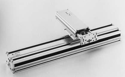
42 Pneumatic Equipments Pneumatic Equipments Pneumatic cylinder unit LWL Pneumatic actuator LWL Pneumatic slide table LWL 37 38


43 Pneumatic Equipments, Industrial Robot Pneumatic Equipments, Industrial Robot Rodless cylinder LWL XYZ-axis robot LWHD 39 40
Identification Number
 Identification Number The specification of Micro Linear Way LWL is specified by the identification number, which consists of a model code, a size, a part code, a preload symbol, a classification symbol,
C-Lube Linear Way ML Linear Way L ML LWL
 -Lube Linear ay ML Linear ay L MLLL -Lube Maintenance ree Series -Lube Linear ay ML ML long term maintenance free supported! The aquamarine end plate is the symbol of maintenance free. Identification umber
General Explanation Ⅲ 1 Ⅲ 2
 General Explanation 1 2 Load Rating and Life Life of linear motion rolling guides Even in normal operational status, a linear motion rolling guide will reach the end of its life after a certain period
 Identification The of -Lube Linear Roller Way Super MX is identified by the identification, which consists of model code, size, part code, material symbol preload symbol, classification symbol, interchangeable
C-Lube Linear Way ML ML MLF
 Maintenance ree & U.S. PTTD C-Lube Linear ay Variation of C-Lube Linear ay Shape Length of slide unit Model code C-Lube Linear ay is a linear motion rolling guide, incorporating the C-Lube as a components
 Identification The specification of C-Lube Linear ay is identified by the identification, which consists of a model code, a size, a part code, a material code, a preload symbol, a classification symbol,
Maintenance Free C-Sleeve Linear Way ML ME MH MUL
 Maintenance ree C-Sleeve Linear ay M M MUL CAT-A e aim to be a Technology-Developing company taking customer-need as primary source for the development. ith our original technologies and creativities,
The basic dynamic load rating C is a statistical number and it is based on 90% of the bearings surviving 50 km of travel carrying the full load.
 Technical data Load Rating & Life Under normal conditions, the linear rail system can be damaged by metal fatigue as the result of repeated stress. The repeated stress causes flaking of the raceways and
PROCESS FOR SELECTING NB LINEAR SYSTEM
 The NB linear system is a linear motion mechanism which utilizes the recirculating movement of ball or roller elements to provide smooth and accurate linear travel. NB offers a wide range of linear motion
Maintenance Free C-Sleeve Linear Way
 U.S. PATTD Maintenance ree C-Sleeve Linear ay M M MUL Maintenance free for,000 km or or years CAT- Printed in Japan 0.0 (SIG Maintenance ree & C-Sleeve Linear ay strives to be a leader in Technology. Our
Miniature (SEB Type) Tapped-Hole rail Types: Slide guides with clearance holes are standard and tapped holes are available upon request.
 Tapped-Hole rail Types: Slide guides with clearance holes are standard and tapped holes are available upon request.") Miniature (SE Type) The SE type slide guide is a linear motion bearing in which the ball elements roll along two tracking grooves. This is the smallest and lightest slide guide series offered by Nippon
Miniature (SE Type) The SE type slide guide is a linear motion bearing in which the ball elements roll along two tracking grooves. This is the smallest and lightest slide guide series offered by Nippon
Points. Precision Positioning Table TU. Variation. Major product specifications With flange
 9 0 Precision Positioning Table Ball screw inear Points lide table with high accuracy and high rigidity in a single structure lide table Compact and slim type positioning table with an original U-shaped
Ball screw. Linear. Coupling cover. 1Positioning table of a structure with enhanced sealing property. 3 High corrosion resistance
 Cleanroom Precision Positioning Table TC Ball screw TC EB Slide table inear Way Side cover Stainless sheet Motor bracket inear Coupling cover Pipe threads for suction connector Points ight weight, low
The SynchMotion. Retainer
 106 G99TE13-0809 Linear Guideways QE Series 2-9 QE Type Quiet Linear Guideway, with SynchMotion TM Technology The development of HIIN-QE linear guideway is based on a four-row circular-arc contact. The
Cam Roller Guides. The Drive and Control Company. Service Automation. Electric Drives and Controls. Linear Motion and Assembly Technologies
 Industrial Hydraulics Electric Drives and Controls Linear Motion and Assembly Technologies Pneumatics Service Automation Mobile Hydraulics Cam Roller Guides The Drive and Control Company Linear Motion
ENGINEERING INFORMATION TABLE OF CONTENTS SHAFT AND HOUSING FITS LUBRICATION LIFE AND LOAD RATINGS RADIAL CLEARANCE CHART
 ENGINEERING INFORMATION TABLE OF CONTENTS ENGINEERING INFORMATION SHAFT AND HOUSING FITS LUBRICATION LIFE AND LOAD RATINGS RADIAL CLEARANCE CHART SHAFT AND HOUSING FITS FOR METRIC RADIAL BALL AND ROLLER
Precision Ball Screw/Spline
 58-2E Models BNS-A, BNS, NS-A and NS Seal Outer ring Shim plate Seal Spline nut Seal Collar Shim plate Seal End cap Ball Outer ring Ball screw nut Outer ring Ball Retainer Retainer Outer ring Point of
Miniature Slide Guide Series with Retained Ball now Offers Complete Selection
 Miniature Slide Guide Series with Retained Ball now Offers Complete Selection Wide type of Miniature Slide Guide, providing greater allowable moment, is now available with retained ball structure. Due
SLIDE GUIDE SGL TYPE SLIDE GUIDE BLOCK TYPES ACCURACY
 SGL YPE he N slide is a linear motion earing utilizing the rotational motion of all elements along four rows of raceway grooves. It can e used in various applications due to its compactness and high load
Linear Motion Rolling Guide series with. Capillary Plate. Lubrication parts U.S. PATENTED CAT- 5921D. More interchangeable models now available!
 Linear Motion Rolling Guide series with Capillary Plate Lubrication parts CAT- 921D U.S. PATENTED More interchangeable models now available! Linear Motion Rolling Guide series with Capillary Plate Applicable
SLIDE GUIDE SGL TYPE SLIDE GUIDE BLOCK TYPES ACCURACY
 SGL YPE he N slide is a linear motion earing utilizing the rotational motion of all elements along four rows of raceway grooves. It can e used in various applications due to its compactness and high load
R-Plus System Frontespizio_R_PlusSystem.indd 1 11/06/ :32:02
 R-Plus System R-Plus System R-Plus system R-Plus system description Fig. R-Plus system R-Plus System is Rollon s series of rack & pinion driven actuators. Rollon R-Plus System series linear units are designed
The SKF model for calculating the frictional moment
 The SKF model for calculating the frictional moment The SKF model for calculating the frictional moment Bearing friction is not constant and depends on certain tribological phenomena that occur in the
Slide unit. Casing. Model. 3 Size. Linear Way E LWE. 6 Material type. 9 Interchangeable
 -Lube Maintenance ree Series -Lube Linear Way M M period maintenance free supported! Te aquamarine end plate is te symbol of maintenance free. Identification umber and Specification xample of an identification
Low Decibel Linear Way E
 U.S. PATNTD Low Decibel Linear Way LWQLWTQLWSQ Low Decibel Linear Way series Sape lange type mounted from bottom Low Decibel Linear Way is a linear motion rolling guide for smoot and quiet motion. Its
Product Description. Further highlights. Outstanding features. 4 Bosch Rexroth Corporation Miniature Linear Modules R310A 2418 (2009.
 4 Bosch Rexroth orporation Miniature Linear Modules R310A 2418 (2009.05) Product Description Outstanding features Rexroth Miniature Linear Modules are precise, ready-to-install linear motion systems that
Example of Calculating the Nominal Life
 Condition (Horizontal Installation) Assumed model number : KR 5520A LM Guide unit (C = 800N, C 0 = 6900N) Ball Screw unit (C a = 620N, C 0a = 9290N) Bearing unit(fixed Side) (C a = 7600N, P 0a = 990N)
MonocarrierTM Monocarrier
 Monocarrier TM Significantly saves designing load of machinery through an integration of linear motion components in one unit. Demonstrates high performance in a wide range of applications, including assembling
Monoca rrier TM CBLOCK C1-C22 C23-C68 C69-C88
 C-1 TM 1. Features C1 2. Classifications and Series C. Optional Components C. Selection of.1. Procedures for Selecting C.2. Rigidity C.. Maximum Speed C.. Accuracy Grade C.. Stroke and Ball Screw Lead
BEARINGS Pillow Blocks
 The bearing size is usually selected according to the required bearing life and reliability under a specified type of load charged on the bearing. The load applied to the bearing operating under a static
SNL plummer block housings, 2, 3, 5 and 6 series Other bearing housings Large SNL plummer block housings
 Bearing housings SNL plummer block housings, 2, 3, 5 and 6 series... 1033 Other bearing housings... 1058 Large SNL plummer block housings... 1058 SONL plummer block housings... 1059 SDG plummer block housings...
Bearing Internal Clearance and Preload
 . Bearing Internal Clearance and Preload. Bearing internal clearance Bearing internal clearance is the amount of internal free movement before mounting. As shown in Fig.., when either the inner ring or
CTV series CHARACTERISTICS LINEAR UNITS
 CTV series CHARACTERISTICS The CTV series describes s with a precision ball screw drive and two parallel, integrated, Zerobacklash rail guides. Compact dimensions allow high performance features such as,
ER2 Short-head Electric Chain Hoist
 O/M NO.SHER2-0903-CE-00 ER2 Short-head Electric Chain Hoist (250kg to 5t) Operation Manual (SHER2M/SHER2SG/SHER2SP) Introduction The KITO Short-head Electric Chain Hoist is intended for effective use in
Series MHY2/MHW Angular Gripper. Cam actuation style is now standardized! MHZ2 MHZJ2 MHQ MHL2 MHR MHK MHS MHC2 MHT2 MHY2 MHW2 MRHQ 2.
 18 Angular Gripper Cam Style Rack & Pinion Style Series / Cam actuation style is now standardized! 2.8-1 18 Angular Gripper 18 Angular Gripper Series / Cam Style Rack & Pinion Style Series / Series MHY/Cam
E 094 E 103 E 143. Tank top mounting Connection up to G1 Nominal flow rate up to 135 l/min e
 R e t u r n F i l t e rs E 094 E 103 E 143 Tank top mounting Connection up to G1 Nominal flow rate up to 135 l/min 20.30-5e D e s c r i p t i o n Application In the return line circuits of hydraulic systems.
LINE TECH Linear Modules. Ready to built-in linear modules with drive
 Ready to built-in linear modules with drive Anodized profile, produced in extrusion molding method Linear rail guiding system (LM3 LM5) Actuation by ball screw, high-helix lead _ screw or toothed belt
Ball Reverser. Ball Reverser Actuator. FLENNOR Power Transmission Products. Patented
 Ball Reverser FLENNOR Power Transmission Products Ball Reverser Actuator Patented Ball Reverser Principle General Information NORCO'S Ball Reverser Actuator is a unique actuator which provides automatic
Linear guide drives. Synchronous shafts The use of synchronous shafts enables several linear axes to be operated with one drive.
 Linear guide drives Drive concept The linear guides are driven via the hollow shaft in the drive head. The drive head is used to directly install a motor or alternatively (in connection with a center shaft)
FOUR-POINT CONTACT SLEWING RINGS - without gear [ O ]
![FOUR-POINT CONTACT SLEWING RINGS - without gear [ O ]](/thumbs/96/126795264.jpg "FOUR-POINT CONTACT SLEWING RINGS - without gear [ O ]") FOUR-POINT CONTACT SLEWING RINGS - without gear [ O ] Number of the Loading Boundary Dimensions Static Ax.Basic Load Rating Designation Weight Abutment Dimensions Curve d D T C oa G J 1 J 2 N 1 N 2 n 1
FOUR-POINT CONTACT SLEWING RINGS - without gear [ O ] Number of the Loading Boundary Dimensions Static Ax.Basic Load Rating Designation Weight Abutment Dimensions Curve d D T C oa G J 1 J 2 N 1 N 2 n 1
Drive Units with Ball Screw Drives R310EN 3304 ( ) The Drive & Control Company
 The Drive & Control Company") Drive Units with Ball Screw Drives R310EN 3304 (2007.05) The Drive & Control Company Linear Motion and Assembly Technologies Ball Rail Systems Roller Rail Systems Linear Bushings and Shafts Precision Ball
Drive Units with Ball Screw Drives R310EN 3304 (2007.05) The Drive & Control Company Linear Motion and Assembly Technologies Ball Rail Systems Roller Rail Systems Linear Bushings and Shafts Precision Ball
Sliding Contact Bearings
 Sliding Contact Bearings Classification of Bearings 1. According to the direction of load to be supported. The bearings under this group are classified as: (a) Radial bearings (b) Thrust bearings. In radial
STAF Linear Guide. STAF Linear Guide Integrated Rail for Non Cage Type and Cage Type.
 STAF Linear Guide STAF Linear Guide Integrated Rail for Non Cage Type and Cage Type www.staf.com.tw A. Terms of Linear Guide 1-1 Main Factors a. Lifetime and Load of Linear Guide Selection of linear guide
1 High precision, high rigidity positioning table
 TSHM CTHM 11 116 Precision Positioning Table H Ball screw TSH M Ball screw Slide table inear Way Bed inear Points 1 High precision, high rigidity positioning table High precision, high rigidity positioning
Product description. Compact Modules. Characteristic features. Further highlights
 4 Compact Modules Product description Characteristic features Five fine-tuned sizes based on a compact precision aluminum profile with two integrated pre-tensioned ball rail systems Identical external
Rodless cylinders Series 1600
 Rodless cylinders Series 00 Basic version 0.Ø.stroke.0.M Max. stroke mt.) AL AI RA RB AF TC AM L LA+stroke AH TD AE TA RV Possibility of a single feed cylinder head AI AP AB AC AD TD TE TB AG RT Left head
AF SERIES AWEA MECHANTRONIC CO., LTD. High Performance Vertical Machining Center AGENT ISO 9001 ISO 14001
 AWEA MECHANTRONIC CO., LTD. HEADQUARTERS 629, Suezhetou Section, Kwanpu Rd., Wenshan Li, Hsinpu, Hsinchu, Taiwan TEL : +886-3-88-191 FAX : +886-3-88-19 Website : www.awea.com CENTRAL TAIWAN SCIENCE PARK
Identification system for short product names. Changes/amendments at a glance. 2 Bosch Rexroth AG OBB omega modules R ( )
") Omega Modules OBB 2 OBB omega modules R9990079 (206-05) Identification system for short product names Short product name Example: O B B - 085 - N N - System = Omega module Guideway = Ball Rail System Drive
Omega Modules OBB 2 OBB omega modules R9990079 (206-05) Identification system for short product names Short product name Example: O B B - 085 - N N - System = Omega module Guideway = Ball Rail System Drive
ISO INTERNATIONAL STANDARD. Rolling bearings Thermal speed rating Calculation and coefficients
 INTERNATIONAL STANDARD ISO 1512 First edition 200-12-01 Rolling bearings Thermal speed rating Calculation and coefficients Roulements Vitesse de référence thermique Calculs et facteurs de correction Reference
ADVANCED MOTION TECHNOLOGIES CORP.
 LINEAR GUIDEWAY ADVANCED MOTION TECHNOLOGIES COR. No.7, Lane 89, Chung Shan Rd., Shen Kang Hsiang, Taichung Hsien 49, Taiwan TEL: +886464 FAX: +8864686 Email: amt.info@pmiamt.com.tw Web site: www.pmiamt.com
S.C. Rulmenti S.A. Barlad Romania Republicii Street No
 SELECTION OF BEARING SIZE Basic load ratings The size of a bearing is selected considering the load in the used rolling bearing and also depends on the operational rating life and prescribed operating
Experiment Instructions. Deformation of Frames
 Experiment Instructions SE 0.20 Deformation of Frames Experiment Instructions This manual must be kept by the unit. Before operating the unit: - Read this manual. - All participants must be instructed
Coating K = TFE wear resist, dry lubricant Kerkote X = Special coating, (Example: Kerkote with grease)
") HAYD: 0 WGS0 Low Profile, Screw Driven Slide WGS0 Linear Rail with Hybrid 000 Series Size Single and Double Stacks and 000 Series Size Single and Double Stacks Kerk Motorized WGS Linear Slide utilizes
HAYD: 0 WGS0 Low Profile, Screw Driven Slide WGS0 Linear Rail with Hybrid 000 Series Size Single and Double Stacks and 000 Series Size Single and Double Stacks Kerk Motorized WGS Linear Slide utilizes
Rotary modules.
 Rotary modules www.comoso.com www.comoso.com Rotary modules ROTARY MODULES Series Size Page Rotary modules RM swivel unit 156 RM 08 160 RM 10 162 RM 12 164 RM 15 168 RM 21 172 RM rotor 176 RM 50 180 RM
Dynamic Analysis for Needle Roller Bearings Under Planetary Motion
 NTN TECHNICAL REVIEW No.75 2007 Technical Paper Dynamic Analysis for Needle Roller Bearings Under Planetary Motion Tomoya SAKAGUCHI A dynamic analysis tool for needle roller bearings in planetary gear
( ) Calculating the Nominal Life. Nominal Life Equation for an LM Guide Using Balls. Nominal Life Equation for the Oil-Free LM Guide L = ( C L =
 Calculating the Nominal Life. Nominal Life Equation for an LM Guide Using Balls. Nominal Life Equation for the Oil-Free LM Guide L = ( C L =") Point of Selection The service life of an LM Guide is subject to variations even under the same operational conditions. Therefore, it is necessary to use the nominal life defi ned below as a reference
Point of Selection The service life of an LM Guide is subject to variations even under the same operational conditions. Therefore, it is necessary to use the nominal life defi ned below as a reference
BNA Series. PLENUM FAN with Backward Wheels
 BNA Series PLENUM FAN with Backward Wheels BNA Series BNA Series Plenum Fans Backward wheels Kruger Plenum Fans are designed for air handling applications where the fan operates unhoused within a plenum.
Thermohydrodynamic Lubrication Characteristics of High-Speed Tilting Pad Journal Bearings
 Thermohydrodynamic Lubrication Characteristics of High-Speed Tilting Pad Journal Bearings OGATA Hideki : Manager, Vibration Engineering & Tribology Department, Research Laboratory, Corporate Research &
Linear Guides SH Series
 inear Guides S Series Ball Slide Models: A, B Front view of A and B types Side view of B type MRO B1 W B 4-M l 1 T MYO K E B 3 W2 W1 Model o. SA SB SA SB S2A S2B SA SB S3A S3B S4A S4B SA SB Assembly Ball
Load Washers. Force. for Forces of 7, kn. F z. Type 9001A A 9081B, 9091B
 Force Load Washers for Forces of 7,5... 1 200 kn Type 9001A... 9071A 9081B, 9091B 1-component force sensor for measuring dynamic and quasistatic forces in z direction. F z Calibrated measuring range 100
T20WN. Data Sheet. Torque transducers. Special features. Installation example with bellows couplings. B en
 T20WN Torque transducers Data Sheet Special features - Nominal (rated) torques 0.1 N m, 0.2 N m, 0. N m, 1 N m, 2 N m, N m, 10 N m, 20 N m, 0 N m, 100 N m, 200 N m - Accuracy class: 0.2 - Contactless transmission
TE 75R RESEARCH RUBBER FRICTION TEST MACHINE
 TE 75R RESEARCH RUBBER FRICTION TEST MACHINE Background: The Research Rubber Friction Test Machine offers the ability to investigate fully the frictional behaviour of rubbery materials both in dry and
Chapter 11. Bearing Types. Bearing Load. The Reliability Goal. Selection of Tapered Roller Bearings
 Chapter 11 Rolling Contact Bearing Bearing Types Bearing Life Bearing Load Bearing Survival The Reliability Goal Selection of Ball and Straight Roller Bearings Selection of Tapered Roller Bearings 1 Introduction
Technical Data Sheet 3ψ Infrared Piranha
 Technical Data Sheet 3ψ Infrared Piranha Features High reliability High total radiated power Peak wavelength λp=730nm Low forward voltage Pb free The product itself will remain within RoHS compliant version.
Friction in Anti-friction Bearings
 Tribology Prof. Dr. Harish Hirani Department of Mechanical Engineering Indian Institute of Technology, Delhi Lecture No. # 32 Friction of Rolling Element Bearing Welcome to thirty second lecture of video
Calculating the Applied Load
 The LM Guide is capable of receiving loads and moments in all directions that are generated due to the mounting orientation, alignment, gravity center position of a traveling object, thrust position and
RGS08 Linear Rails: RGS08 Non-Motorized With and Without Guide Screw. RGS08 Non-Motorized Linear Rails
 RGS08 RGS08 Non-Motorized With and Without Guide RGS08 Non-Motorized Linear Rails RG Series linear rails are available: RGS08 Non-Motorized, -driven linear rail RGS08 Non-Motorized linear rail without
ORTHOBLOC 3000 Drive systems Maintenance
 15 en 284 261 282 113 130 120 061 002 264 193 099 001 25 063 65 119 112 133 252 254 1 115 118 04 ORTHOBLOC 3000 Maintenance NOTE LEROY-SOMER reserves the right to modify the characteristics of its products
3mm Photodiode PD204-6B
 3mm Photodiode Features Fast response time High photo sensitivity Small junction capacitance Pb free This product itself will remain within RoHS compliant version. Description is a high speed and high
second PLSA line R310EN 3308 ( )
") 01_1 Planetary st Headline_36 Screw Assemblies pt/14.4 mm second PLSA line R310EN 3308 (2011-09) 2 Planetary Screw Assemblies PLSA Planetary Screw Assemblies PLSA Product Overview 3 Nuts, Screws, Screw
01_1 Planetary st Headline_36 Screw Assemblies pt/14.4 mm second PLSA line R310EN 3308 (2011-09) 2 Planetary Screw Assemblies PLSA Planetary Screw Assemblies PLSA Product Overview 3 Nuts, Screws, Screw
For ASME Committee use only.
 ð15þ KD-232 PROTECTION AGAINST LOCAL FAILURE In addition to demonstrating protection against plastic collapse as defined in KD-231, the local failure criteria below shall be satisfied. KD-232.1 Elastic
Selection Calculations For Linear & Rotary Actuators
 H-8 For Electric Linear Slides and Electric Cylinders First determine your series, then select your product. Select the actuator that you will use based on the following flow charts: Selection Procedure
DESIGN AND APPLICATION
 III. 3.1 INTRODUCTION. From the foregoing sections on contact theory and material properties we can make a list of what properties an ideal contact material would possess. (1) High electrical conductivity
EVERLIGHT ELECTRONICS CO., LTD.
 Lead (Pb) Free Product - RoHS Compliant Feature Piranha package. Colorless clear resin. Low thermal resistance Packaged in tubes for automatic insertion equipment. Total flux: 7150 to 14250 mlm at 70mA.
RGS06 Linear Rails: RGS06 Non-Motorized With and Without Guide Screw. RGS06 Non-Motorized Linear Rails
 on-motorized With and Without Guide on-motorized Linear Rails RG Series linear rails are available: on-motorized, -driven linear rail on-motorized, Wide format, -driven linear rail on-motorized, Wide format,
SKF actuators available for quick delivery. Selection guide
 SKF actuators available for quick delivery Selection guide A wide range of SKF actuators available for quick delivery Industrial actuator 24 Volt DC Load range 1 000 to 4 000 N Speed range 5 to 52 mm/s
Planetary Screw Assemblies PLSA
 Planetary Screw Assemblies PLSA R310EN 3308 (2011-09) The Drive & Control Company C/ Centauro, 13 Área Empresarial Las Cubiertas 28971-Griñón (Madrid) T. 0034 91 126 6627 info@diversiatec.com www.diversiatec.com
5mm Silicon PIN Photodiode, T-1 3/4 PD333-3B/H0/L2
 Features Fast response time High photo sensitivity Small junction capacitance Pb free This product itself will remain within RoHS compliant version. Description is a high speed and high sensitive PIN photodiode
INVESTIGATION OF BALL SCREWS FOR FEED DRIVE 1. INTRODUCTION
 Journal of Machine Engineering, Vol. 3, No. 4, 203 ball screws, machine tools, rigidity, impact forces Jerzy Z. SOBOLEWSKI INVESTIGATION OF BALL SCEWS FO FEED DIVE The paper presents a method which enables
Tribology Prof. Dr. Harish Hirani Department of Mechanical Engineering Indian Institute of Technology, Delhi
 Tribology Prof. Dr. Harish Hirani Department of Mechanical Engineering Indian Institute of Technology, Delhi Lecture No. # 29 Rolling Element Bearings (Contd.) Welcome to 29 th lecture of video course
Press. Allbest Creative Development Ltd. (ALLBEST)
") Press Allbest Creative Development Ltd. (ALLBEST) Technology Portfolio Equal-hydrostatic press (cold isostatic press) Hydraulic press for fibercement sheet and other building materials Hydraulic press
Press Allbest Creative Development Ltd. (ALLBEST) Technology Portfolio Equal-hydrostatic press (cold isostatic press) Hydraulic press for fibercement sheet and other building materials Hydraulic press
CL-L102-C7D. 1. Scope of Application. These specifications apply to LED package, model CL-L102-C7D. 2. Part code
 Specification sheet 1/10 1. Scope of Application These specifications apply to LED package, model. 2. Part code Series L102 : High power LED for general lighting Watt Class C7 : 7 watt class package Lighting
Study of Rupture Directivity in a Foam Rubber Physical Model
 Progress Report Task 1D01 Study of Rupture Directivity in a Foam Rubber Physical Model Rasool Anooshehpoor and James N. Brune University of Nevada, Reno Seismological Laboratory (MS/174) Reno, Nevada 89557-0141
Double Layer Capacitors. PN: NEX_ series & NED_ series
 Rev B - August 2010 www.niccomp.com Technical support: tpmg@niccomp.com Double Layer Capacitors PN: NEX_ series & NED_ series NEXC SMT Reflow Soldering NEXA / NEXG NEXS / NEXT Low Profile Radial LDD NEXM
AE302,ME302,DAE14,DME14
 AE302,ME302,DAE14,DME14 III SEMESTER DIPLOMA EXAMINATION, JANUARY-2013 MANUFACTURING TECHNOLOGY-I Time: 3 Hours Max. Marks: 75 GROUP A : Answer any three questions. (Question No. 1 is compulsory) Q.1 What
3mm Advanced Super Flux LEDs B84-YSC-A1T1U1DH-AM
 3mm Advanced Super Flux LEDs Feature RoHS compliant. Piranha package. Colorless clear resin. Low thermal resistance Packaged in tubes for automatic insertion equipment. Total flux: 7150 to 14250 mlm at
ANGULAR CONTACT BALL BEARINGS PASSED BY ELECTRIC CURRENT
 6th INTERNATIONALMULTIDISCIPLINARY CONFERENCE ANGULAR CONTACT BALL BEARINGS PASSED BY ELECTRIC CURRENT Racocea Cristina, Racocea Cezar, Nacu Ionuţ Technical University Gh. Asachi of Iasi Abstract. The
Digital display Pressure range ON/OFF output Linear output Model No Positive pressure 0 to 98 kpa (0 to 1 kgf/cm 2 ) NPN open collector o 1 to o5
 NPN open collector o 1 to o5") Pressure Sensor E8CC with Built-in Microcomputer and Digital Display and New E8CB General-purpose Model Withstands a of 490 kpa (5 kgf/cm 2 ) and highly reliable. Incorporates a two-turn adjuster ensuring
Pressure Sensor E8CC with Built-in Microcomputer and Digital Display and New E8CB General-purpose Model Withstands a of 490 kpa (5 kgf/cm 2 ) and highly reliable. Incorporates a two-turn adjuster ensuring
Here is what you will be able to do when you complete each objective: 1. State the general laws of static and kinetic friction.
 Friction I Learning Outcome When you complete this module you will be able to: Describe and solve problems involving friction. Learning Objectives Here is what you will be able to do when you complete
ED 701 General Industry Pressure Transmitter
 ED 701 General Industry Pressure Transmitter Standard industrial process connections Complete range of electrical connections 4... 20 ma and Voltage outputs Accuracy: 0.1%, 0.2% and 0.4% FS Quick response
MLCC APPLICATION GUIDE
 MLCC APPLICATION GUIDE 1/11 No. Process Condition 1 Operating Condition (Storage) 1) The capacitor must be stored in an ambient temperature between 5 ~ 40 with a relative humidity of 20 ~ 70%. The products
IBV Series Z Alloy Steel Inverted Bucket Vertical Steam Trap
 Local regulations may restrict the use of this product to below the conditions quoted. In the interests of development and improvement of the product, we reserve the right to change the specification without
E8EB-N0C2B E8EB-N0B2B
 Slim Sensor CSM DS_E 1 Ideal for Workpiece Position and Original Checking The to 1 kpa model can be used for workpiece position checking. The to 1MPa model is ideal for original pressure checking. Degree
IBV Series C Carbon Steel Inverted Bucket Vertical Steam Trap
 Local regulations may restrict the use of this product to below the conditions quoted. In the interests of development and improvement of the product, we reserve the right to change the specification without
Low Profile Slide Table
 Low Profile Slide Table Series ø, ø, ø1, ø Low-profile and compact type, air slide table with the construction of guide and cylinder aligned in parallel. Neat appearance Protecting stopper section with
LAMP /T2C1-4WYC
 Features Popular T-1 3/4 round package High luminous power Typical chromaticity coordinates x=0.30, y=0.29 according to CIE1931 Bulk, available taped on reel. ESD-withstand voltage: up to 4KV The product
Module 7 Design of Springs. Version 2 ME, IIT Kharagpur
 Module 7 Design of Springs Lesson 1 Introduction to Design of Helical Springs Instructional Objectives: At the end of this lesson, the students should be able to understand: Uses of springs Nomenclature
LAWS OF MOTION Newtons laws of motion. (i) First law: Law of inertia. Every body continues to be in its state of rest or of uniform motion in a
 First law: Law of inertia. Every body continues to be in its state of rest or of uniform motion in a") LAWS OF MOTION Newtons laws of motion. (i) First law: Law of inertia. Every body continues to be in its state of rest or of uniform motion in a straight line unless compelled to change that state by an
LAWS OF MOTION Newtons laws of motion. (i) First law: Law of inertia. Every body continues to be in its state of rest or of uniform motion in a straight line unless compelled to change that state by an
THE LOSMANDY G-11 MOUNT
 Checking the parts THE LOSMANDY G-11 MOUNT Depending on which accessories you ordered, your G-11 mount was shipped in four or more boxes. The contents of each box are as follows: Equatorial Mount Adjustable
ISO INTERNATIONAL STANDARD. Rolling bearings Linear motion rolling bearings Part 2: Static load ratings
 INTERNATIONAL STANDARD ISO 14728-2 First edition 2004-06-01 Rolling bearings Linear motion rolling bearings Part 2: Static load ratings Roulements Roulements à mouvement linéaire Partie 2: Charges statiques