Nonlinear Seismic Analysis of Buried Pipelines During Liquefaction
|
|
|
- Catherine Farmer
- 6 years ago
- Views:
Transcription


1 Missouri University of Science and Technology Scholars Mine International Conference on Case Histories in Geotechnical Engineering (8) - Sixth International Conference on Case Histories in Geotechnical Engineering Aug th - Aug 6th Nonlinear Seismic Analysis of Buried Pipelines During Liquefaction Amir M. Halabian Isfahan University of Technology, Isfahan, Iran S. Hamid Hashemolhosseini Isfahan University of Technology, Isfahan, Iran Mehdi Rezaei Isfahan University of Technology, Isfahan, Iran Follow this and additional works at: Part of the Geotechnical Engineering Commons Recommended Citation Halabian, Amir M.; Hashemolhosseini, S. Hamid; and Rezaei, Mehdi, "Nonlinear Seismic Analysis of Buried Pipelines During Liquefaction" (8). International Conference on Case Histories in Geotechnical Engineering.. This Article - Conference proceedings is brought to you for free and open access by Scholars Mine. It has been accepted for inclusion in International Conference on Case Histories in Geotechnical Engineering by an authorized administrator of Scholars Mine. This work is protected by U. S. Copyright Law. Unauthorized use including reproduction for redistribution requires the permission of the copyright holder. For more information, please contact scholarsmine@mst.edu.
2 NONLINEAR SEISMIC ANALYSIS OF BURIED PIPELINES DURING LIQUEFACTION Amir M. Halabian S. Hamid Hashemolhosseini Mehdi Rezaei Faculty of Civil Engineering Faculty of Mining Engineering Faculty of Civil Engineering Isfahan University of Technology Isfahan University of technology Isfahan University of technology Isfahan, Iran Isfahan, Iran Isfahan, Iran ABSTRACT The safety of buried pipelines during earthquakes has involved a great deal of attention in last few years. Important characteristics of buried pipelines are that they cover large areas and can be subjected to a variety of geotectonic hazards. Earthquake damages to buried pipelines can be attributed to transient ground deformations (TGD), permanent ground deformations (PGD) or both. PGD occurs as a result of surface faulting, liquefaction, landslides, and differential settlement from consolidation of cohesionless soil. To evaluate seismic behavior of buried pipelines subjected to large values of permanent ground deformations, appropriate non-linear cyclic stressstrain relationship should be implemented in any numerical method. Among the phenomena, which cause permanent ground deformations, the settlement and lateral spreading induced by liquefaction are considered as the main cause of damage in buried structures. Therefore, this study is aimed to take into account the potential of liquefaction during an earthquake into the numerical analysis of buried pipelines using FEM. During the earthquake, the soil volume and also pore-pressure water is changed and therefore as saturated loose sands undergo simple shear deformations, the stiffness at any time is changed as the function of mean normal effective stress. In this study, a hypo-elastic model is adopted for the soil to evaluate changes in the pore pressures and also effective stresses during the excitation. In a finite element modeling, for the areas not expecting the liquefaction to occur, the pipe is modeled using beam elements and soil is modeled by some bi-linear springs; while for liquefied areas, the pipe is modeled by shell elements and solid elements are used to model the surrounding soil. INTRODUCTION A great deal of study has been done regarding the safety of buried pipelines in the last few years. Since buried pipeline networks cover wide areas, therefore they may be subjected to a variety of geotectonic hazards including spatial ground motions. A number of severe earthquakes in recent years such as 995 Kobe in Japan, the 999 Chi-Chi in Taiwan and the 999 Kocaeli in Turkey have shown that the damage mechanism of buried pipelines could be mainly caused by post-earthquake hazards such as fault movement, land sliding and also liquefaction-induced soil displacements all so-called Permanent Ground Deformation (PGD). Therefore performance of buried pipelines may significantly be affected by permanent ground deformations during and after earthquake. The widespread soil liquefaction that happened in Japan during the 995 Hyogoken-Nambu earthquake (Kobe earthquake) caused tremendous damage to various lifeline facilities resulting flotation of buried pipelines. Since then serious concern to buried pipelines was realized by researchers due to damages occurred resulting from liquefaction as one of cause of permanent ground deformation. A detailed review of the literature on earthquake response of underground pipeline systems reveals that great progress has been acquired (ORourke and Lane (989)) in seismic response of buried pipelines subjected to fault movement. The pseudo-static method has been used widely in analyzing the soil-pipe mutual system. This method only models the soil as springs simply, and cannot consider the reduction of soil intensity. Under a seismic action for saturated sands, because of the remarkable nonlinear behavior and the solid-liquid twophase character of the soil, the dynamic properties of the soil will be changed significantly and the deformation of soil is mostly depended on the development of pore water pressure. This nonlinear cyclic behavior of the soil may influence the dynamic response of the soil-pipeline system. This study focused primarily on pipeline response resulting from earthquake deformation induced by liquefaction. Therefore, the effect of soil cyclic nonlinear behavior, introduced by soil liquefaction, on the soil-pipe interaction phenomena is evaluated throughout a time history analysis. Knowing this fact that implementing advanced constitutive Paper No. 4.6
3 models into any dynamic numerical analysis method requires remarkable computational efforts, a very simple algorithm to define the hysteretic loops when liquefiable sands are subjected to ground motions during loading-reloading phase of excitation is developed. A practical diameter of Gas pipelines embedded in different soil layers are chosen to reveal the unfavorable effects of the soil-structure interaction phenomenon during liquefaction. Using the simple hysteretic algorithm for saturated soils developed here in this study, a 3D coupled finite element modeling is carried out to trace the stresses and deformations of the pipe and the adjacent soil during the initial liquefaction. For a given site, appropriate input ground motions are chosen to enforce the inelastic behavior of the soil. The role of several parameters on both the pipe s response and induced soil strains are extensively studied. In a framework of parametric studies, the present work can be extended to the different soil profiles and properties as well as the characteristics of the input motion (i.e. amplitude, frequency content, Arias intensity). CONSTITUTIVE MODEL FOR LIQUEFIABLE SOIL The earthquake response of saturated sands is a very complicated process due to coupling between the dissipation and the re-distribution of pore water pressure and also the soil frame deformation during cyclic loading. Dynamic shear stresses and shear strain generated by the earthquake cause slip at grain contacts and then the volume could be changed and consequently the pore-pressure during the event may be increased until all effective stresses are eliminated from the system. In this state the sand has significant loss of shearing resistance and deform like a liquid. Therefore, one can say that the soil shear modulus of elasticity at a given strain level is a function of normal effective stresses. As a result, when computing the response of saturated sands to a given earthquake, important factors can be classified as: the soil initial shear modulus, the variation of shear modulus with shear strain and generation and dissipation of pore-water pressures. To simulate the liquefaction, the soil in the model should be assumed to show the hysteretic characteristics based on the undrained conditions. Therefore, it is very important to consider the hysteretic characteristics on the effective stressstrain relationships of soils. In this study, the constitutive law developed by Finn and Lee (977) as a hypo-elastic model was employed to evaluate the shear modulus of elasticity as a function of effective shear stress or shear strain. The skeleton curve is given by the following hyperbolic equation (Fig. ): Gm τ = () + G γ / τ ( ) γ m m G m As seen in Fig., is the shear modulus at the initial part of the backbone curve and τ m is the undrained shear strength, both can be obtained by Hardin-Dernevich relation (Prakash, 98): (.973 e) + k Gm = α.( ). σ v () + e 3 τ + K + K = [( σ v (3) m Sinφ ) ( ) ] where e, σ v, K and φ are void ratio, effective vertical stress, confining pressure ratio and soil friction angle, respectively. τ + τ r γ + γ r = f τ τ r γ γ r = f Fig.. Soil stress-strain relationship For each loading-reloading loop, after reversal point, the unloading path is defined as τ τ r γ γ r = f in which τ r and γ r are the shear stress and shear strain at the reversal point. During the liquefaction as the effective stress and soil stiffness decreases, the effect of increased pore pressure is to degrade or soften the soil backbone curve. In the Finn constitutive model, relating the pore pressure variations to the incremental volumetric strain, the rebound shear modulus is expressed as σ v G mn = G m ( ) (5) σ σ v v σ v where and are the current and initial vertical effective stresses. To take into account effect of degrading in the undrained shear strength for the n th cycle, τ mn, can also be evaluated as σ v τ mn = τ m ( ) (6) σ v In this study, an energy dissipation approach was used to modify the Finn model and to predict the reversal point in loading-reloading paths of hysteretic loop. Based on this approach the reversal loading direction is judged by the sign of the dissipated energy increment (the incremental shear work), WS. The shear work increment can be obtained in a FEM analysis as the different between the total incremental work, WT, and the incremental volumetric work, WN, for an increment strain during loading or reloading as (4) Paper No. 4.6
4 W = W W (7) s T N where W T = σ ε + σ ε + σ 33 ε 33 + ( σ ε + σ 3 ε 3 + σ 3 ε 3 ) (8) W N K = 3 =. σ KK ε 3 KK (9) K = The rebound shear modulus can be calculated by effective stresses through a non-linear dynamic analysis. However, in the effective stress analysis the results strongly depend on the constitutive equations and also the level of effective vertical stresses at the different loading-reloading cycles. Therefore in this study, the energy dissipation approach was also used to evaluate the maximum shear modulus at the initial part of each loading-reloading loop as: G mn.( Ws m = Gm ( ) ) () W T where Ws is the total shear work and WT is the total work done to the n th cycle. The parameter m will be obtained throughout a calibration process with the experimental works. The variation of the excess pore water pressure can be obtained using the definition of the effective stress, i.e. v v U = σ σ () The effective stress at a given time, t, can also be evaluated by σ σ v v G = G m t () As it was mentioned the model proposed in this study is a simple model that characterize only liquefaction aspect of saturated sands behavior. Hence, the model parameters should be defined from standard undrained triaxial tests. The implementation of the proposed model in a finite element code has been tested by simulation of a triaxial compression test with initial confining pressure, p, equal to kpa (Habte, 6). The experimental tests was for the soil with initial void ratio of.737 and internal friction angle of 3. Using the finite element code equipped with the proposed non-linear soil constitutive model proposed in this study, an axi-symmetric FE model was developed (shown in Fig. ). The results for the above triaxial test for deviatoric stress versus shear strain are shown in Fig. 3, which is matched with the results reported in Fig. 4 (Habte, 6) in terms of the maximum stress and the number of loops. Fig.. The triaxial test FE model q(kn/m ) Fig. 3. Cyclic undrained triaxial FE model q-ε q curve SOIL-PIPE MODELING The early studies on buried pipelines behavior subjected to permanent ground deformation specially fault movements were focused on the displacements that cause tensile failure of the pipeline using cable theory (Newmark-Hall, 975; Kennedy, 977). Some observations of the damages (V-shape and Z-shape) caused by earthquakes showed that pipelines could undergo out of plane axial and bending deformations due to ground displacements specially when crossing normal faults and in plane axial and bending deformations at reverse faults. Since the cable theory could not satisfy the equilibrium condition for a pipeline crossing a reverse fault, the beam model was developed to consider the bending stiffness of the pipe (Wang and Yeh 985). In the beam model, the large deflection part of the pipe was modeled as a constant curvature curved segment and the remaining part of the pipe, which is small deflection, was treated as a semi-infinite beam on elastic foundation. For the cases that the pipe is subjected to moderate and large movements, this model yielded more realistic than cable model. It has been noticed from past earthquakes that the buried pipelines suffered severe damages εq Paper No
5 due to huge deformations in the pipe section that creates the very large amount of strain. Therefore, the pipe response in some areas is a complicated nonlinear behavior. Since it is difficult for the cable or beam model to analyze the large deformation in the pipe crossing section, the shell FEM model has been proposed in the analysis of fault-crossing pipeline in order to consider the effect of local buckling and wrinkle in the pipe s section (Ariman and Lee, 99). In this study to investigate the effect large deformation in the pipe s sections and also non-linear behavior of liquefiable soil during earthquake a hybrid shell-beam model was adapted to represents the long geometry of soil-pipe system. In this finite element model, the middle part located in the area susceptible to liquefaction has been modeled by shell elements for the pipe and 8-node brick elements for the soil around the pipe. While beam elements are used for the side parts, which are between the fixed point and end points of the shell segment and are subjected to large deformations in the soil-pipe system (Fig. 4). To assess the integrity of the pipelines against ground deformations, it is important to quantitatively evaluate the interaction between the pipelines and the surrounding soil. The shell elements are linked with beam elements to represent sections of straight pipe outside the zone of large localized strain induced by liquefaction. Soil-pipeline interaction in the side parts in response to relative displacement between pipe and soil is modeled with discrete spring elements using a bilinear force-displacement relationship to represent the elasto-plastic nature of the soil-pipeline interaction. Theses springs represent the axial, transverse horizontal and transverse vertical soil restraints. The soil-pipeline interaction specified in the major seismic design guidelines for pipelines has a bilinear force-displacement relationship curve, where the actual experimental results showed due to large ground deformations the soil-pipe interaction decreases as the relative are subjected less deformation, using bilinear representations are sufficiently adequate. Using the load-deformation characteristics for soil-pipeline interaction recommended in ALA, the parameters for mutually perpendicular Winkler s springs are obtained from Table. In the Table, D and H are the pipe s diameter and embedded depth, respectively. C is the soil cohesion and γ is used as effective unit weight. N and N can be obtained from the ch qh Fig. 4. Soil-pipeline system displacement between the soil and pipe increases (Trautmann and O Rourke, 983). However, in this study as the side parts Table. Bilinear soil-pipeline interaction springs parameters [7] Component Ultimate soil force Yield soil displacement + K t π α π γ tan δ Axial u = D C + D H t =. 5 cm (t-x curves) α =.68.3 C + 3 C + C + Transverse Horizontal(p-y curves) p N CD + N γhd =.4 ( H + D ) (. u = ch qh P.5 ) D Transverse Vertical (q-z curves) Q Q d u = N N Upward Direction: cv qv C u D γhd for Clays for Sands N cv = ( H ) D H N qv = ( ϕ ) N q 44 D Downward Direction: D = N ccd + N qγhd + Nγ γ Upward Direction: For Sands: q u = (..) H <. D For Clays: q u = (..) H <. D Downward Direction: For Sands: q u =. D For Clays: q u =. D Paper No
6 charts recommended by ALA (). N, N and N are the soil capacity factors given by ALA (). THE GOVERNING EQUATIONS The displacements and tractions within the soil around the pipe and also inside the pipe are obtained from the governing equation Mpp u && p CppCpi Mii u && i + Cip Cii Mss u && s Csi u & p K ppkpi Cis u & i + Kip Kii Css u & s Ksi c q u p Mpp Kis u i = Mii Kss u s Mss u&& g (3) where M, C and K are the mass, damping and stiffness matrices obtained by the finite-element formulation. The common nodes at the interface of the pipeline and soil or springs representing side regions soil are defined with i ; the nodes of shell elements representing the pipeline and the nodes within the soil around the pipeline in the middle part are defined with p and s, respectively. The mass, the stiffness and the damping at the interface nodes are the sum of the contribution from the pipeline (p) and the soil (s), and are given by p p M s s ii = M ii + Mii ; Cii = C ii + Cii and p s K = K + K (4) ii ii ii As it was noted the liquefiable part of the soil can experience very large amount of strains during the earthquake. Having this kind of non-linearity and also the material and geometric non-linearities of the pipe, using implicit algorithm can be followed with some difficulties in terms of convergences. Therefore, in this study, the explicit approach as a computational efficient approach was adopted to solve the governing equations. The static geometric non-linear analysis under the static situation is essential as a starting point for the non-linear seismic analysis using explicit algorithm, taking the initial conditions at rest for the soil and accounting the initial induced strains to the pipeline due to surcharge loads. The explicit central-difference operator satisfies the dynamic equilibrium equations at the beginning of the increment, t; The accelerations calculated at time are used to advance the t velocity solution to time t + and the displacement solution to time t + t as t + N N i i {} u & {} u& + = {} u& N i i+ i + t γ (5) N N { u} { } { } N i+ u i + ti+ u i = & (6) + The subscript i refers to the increment number in an explicit dynamics step. {u} N velocity vector and { u& &} N is the displacement vector, { u& } N is the is the acceleration vector, where N is the number of degrees of freedom in the model. The explicit integration rule is quite simple but by itself does not provide the computational efficiency associated with the explicit dynamics procedure. The accelerations at the beginning of the time increment using D Alambert s principle are computed by N {} [ ] NJ J u& & = M ({ P } { I } J ) (7) i i where [M] - NJ is the inverse mass matrix, { P} J i load vector, and { I} J i i is the applied is the internal force vector including stiffness and damping forces and J is a numerator. A lumped mass matrix is used because its inverse is simple to compute and because the vector multiplication of the mass inverse by the inertial force requires only N operations. The explicit procedure requires no iterations and no tangent stiffness matrix. The internal force vector, {} I i is assembled from contributions from the individual elements such that a global stiffness matrix need not be formed. The explicit procedure integrates through time by using many small time increments. The central-difference operator is conditionally stable, and the stability limit for the operator (with no damping) is given in terms of the highest frequency of the system as t (8) ω max With damping, the stable time increment is given by t ( + ζ max ζ max ) (9) ω max where ω max is the highest natural frequency and ζ max is the fraction of critical damping in the mode with the highest frequency. EXAMPLE CALCULATIONS To investigate the effect of liquefaction on seismic behavior of buried pipelines, using the model developed in this study, a gas pipeline with a diameter of 6 mm, 5m length and 9.5 mm wall thickness was used. The liquefaction zone assumed to spread along a m length of the pipeline. The liquefiable zone is designed with a 7m-width and 8m-depth uniform saturated sandy soil space, ground water is set at the ground J Paper No
7 surface; and the steel pipe assumed to be buried at the depth of.5m. Table shows the soil dynamic parameters used in the example. Fig. 5. Bilinear soil-pipeline interaction relationships Soil Parameters Table. Soil Dynamic Parameters Density φ ν E Interface friction Angle Fig. 5 shows the bilinear force-displacement relationships representing the axial, transverse horizontal and transverse vertical soil stiffnesses in the non-liquefiable side parts. To take into account the non-linear behavior of the pipe, steel Type X-6 with Ramberg-Osgood elastoplastic stress-strain relationship was used. The dynamic analyses of the soilpipeline system was carried subjected to Northridge Earthquake (994) followed by the static analysis for the at rest condition under gravity loads. The ground excitation is applied to the bottom boundary conditions horizontally. The boundary adopts Lysmer viscous boundary, which can eliminate the numerical error aroused by the limited region. Besides, the pore water pressure boundary is designed as a complete drain boundary. For the Northridge earthquake excitation, Figs. 6 and 7 show the development of pore water pressure changes with the seismic duration for different depths (element A at the depth of m and element B at the depth of 7m). From the results of Figs. 6 and 7 for the system studied in this paper, the liquefaction will happen after 8s of the earthquake (the first 7s is related to the static loading). It can be seen that after liquefaction occurred the soil strains raise significantly leading to remarkable settlements in the soil-pipeline system (Fig. ). At the shallow depths, as the cyclic strength decreases, pore pressures developed faster and then it can be noted after the initial liquefaction, the maximum shear strain increase significantly. Fig. 8 shows the variation of maximum shear strain during the excitation for the element A. This figure also shows after around 8 seconds of the earthquake, the loss of strength starts to take place as pore water pressure builds up. The stress components for two elements A and B are shown in Figs. 9 and. The results indicated that amount of shear strain that can develop or the amount of loss of shear stress appears to be related by the number of cycles and their magnitude, which occurs in the stress time history after the application of peak stress. To consider the liquefaction effect on deformation of the pipeline, the longitudinal settlement of the pipe is recorded for the 8s of the earthquake. It can be noted from Fig. the general tendency for deformation of the pipe are similar suggested by ALA as y( x) = δ ( cos nπx ) () L CONCLUSION In this paper, an effective stress method and nonlinear constitutive relation model of soil were used to study the development and the dissipation of pore water pressure during a seismic excitation. This very simple algorithm to define the hysteretic loops for liquefiable sands during loading-reloading phase of excitation was implemented into the finite element method. A 3D soil-pipeline model was developed to study the Paper No
8 dynamic behavior of pipelines embedded in liquefiable soils. A suitable contact interface model is adopted to simulate the interaction between pipeline and surrounding soil. Using the 3D methodology developed in this study, a numerical simulation of the full-process liquefaction analysis for an underground pipeline was performed. The results show that the methodology can predict the pore pressure build-up and consequently the loss of soil strength consistent with the liquefaction process. The deformation induced in the pipeline due to liquefaction was found similar to a harmonic settlement. Soil Strain 3.E-.E-.E-.E+ ε E- ε -.E- ε3 ε -3.E- ε3 ε33-4.e- Time(s) Fig. 6. Strains time histories for A- element Soil Strain ε ε ε3 ε ε3 ε33 Time(s) Fig. 7. Strains time histories for A- element 5 Shear stress (KN/m ) Time (s) Fig. 8. Maximum shear stress on saturated soil Soil Stress ( KN/m ) σ 5 σ 5 σ3 σ σ3 σ Time(s) S o il S tres s ( KN/m) Time(s) σ σ σ3 σ σ3 σ33 Fig. 9. Stresses time histories for A- element Fig.. Stresses time histories in A- element Paper No


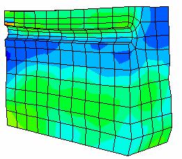
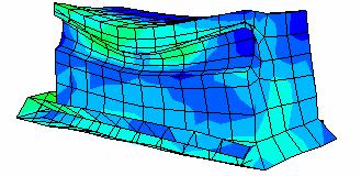
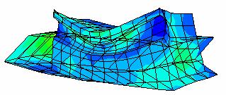
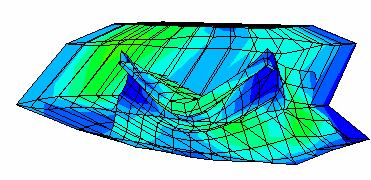
9 Static Equilibrium 5 th second th second 5 th second th second 5 th second Fig.. The soil-pipeline deformation during earthquake excitation Paper No
10 Vertical Displacement (m) Distance(m) Pipe Soil -.9 Trautmann, C. H. and O Rourke, T.D. [983], Behavior of pipe in dry sand under lateral and uplift loading, Geotechnical Engineering Report 83-7, Cornell University. Wang L., R., L., and Yeh Y. [985], A Refined Seismic Analysis and Design of Buried Pipeline for Fault Movement, Earthquake Engineering and Structural Dynamics, vol. 3, Fig.. The pipe deformation during the liquefaction at 8s of earthquake ACKNOWLEDGEMENT This research was funded by by Isfahan Gas Distribution Company as part of project to evaluate the serviceability of Isfahan Gas network during extreme events. Their support is greatly appreciated. REFERENCES American Lifelines Alliance ASCE [], Guidelines for the Design of Buried Steel Pipes. Ariman, T. and Lee B. J. [99], Tension/Bending Behavior of Buried Pipe-lines Subjected to Fault Movements in Earthquake, Proceeding th World Conference on Earthquake Engineering, Madrid, pp Habte, M. A. [6], Numerical and Constitutive Modeling Of Monotonic and Cyclic Loading in Variably Saturated Soils, Ph.D. Thesis, School of Civil and Environmental Engineering, The University of New South Wales, Sydney, Australia. Finn, W. D. and Lee, W. [977], An Effective Stress Model For Liquefaction, ASCE Journal, Geotechnical Engineering Division, GT.6, pp Kennedy, R. P., Chow, A. W. and Williamson, R. A. [977], Fault Movement Effects on Buried Oil Pipeline, Transportation Engineering Journal, ASCE, Vol. 3, No. 5, pp Newmark, N. M. and Hall, W. J., [975], Pipeline Design to Resist Large Fault Displacement, Proceeding of U. S. National Conference on Earthquake Engineering, pp O Rourke, T. and Lane, P. [989], Liquefaction Hazards and Their Effects on Buried Pipelines, NCEER, pp Prakash, S. [98], Soil Dynamics. McGraw-Hill, Inc. Paper No
RESPONSE OF STEEL BURIED PIPELINES TO THREE-DIMENSIONAL FAULT MOVEMENTS BY CONSIDERING MATERIAL AND GEOMETRICAL NON-LINEARITIES
 3 th World Conference on Earthquake Engineering Vancouver, B.C., Canada August -6, 24 Paper No. 694 RESPONSE OF STEEL BURIED PIPELINES TO THREE-DIMENSIONAL FAULT MOVEMENTS BY CONSIDERING MATERIAL AND GEOMETRICAL
Technical Note 16 Equivalent Static Method
 Technical Note 16 Equivalent Static Method Contents Technical Note 21 -... 1 1 Introduction... 1 2 Operational Strain in the Pipeline... 2 3 Seismicity... 2 4 Vertical Uplift... 3 5 Vertical Bearing...
Seismic Response of Structures with Underground Stories Considering Non-Linear Soil-Structure Interaction
 Missouri University of Science and Technology Scholars Mine International Conference on Case Histories in Geotechnical Engineering (8) - Sixth International Conference on Case Histories in Geotechnical
Effective stress analysis of pile foundations in liquefiable soil
 Effective stress analysis of pile foundations in liquefiable soil H. J. Bowen, M. Cubrinovski University of Canterbury, Christchurch, New Zealand. M. E. Jacka Tonkin and Taylor Ltd., Christchurch, New
3-D DYNAMIC ANALYSIS OF TAIYUAN FLY ASH DAM
 3-D DYNAMIC ANALYSIS OF TAIYUAN FLY ASH DAM Jian ZHOU 1, Peijiang QI 2 And Yong CHI 3 SUMMARY In this paper, the seismic stability of Taiyuan Fly Ash Dam in China is studied by using 3-D dynamic effective
SEISMIC RESPONSE ANALYSIS OF UNDERGROUND PIPELINES USING EFFECTIVE STRESS METHOD
 13 th World Conference on Earthquake Engineering Vancouver, B.C., Canada August 1-6, 2004 Paper No. 3223 SEISMIC RESPONSE ANALYSIS OF UNDERGROUND PIPELINES USING EFFECIVE SRESS MEHOD Xiaoqiu AI 1 And Jie
Liquefaction Potential Variations Influenced by Building Constructions
 Earth Science Research; Vol. 1, No. 2; 2012 ISSN 1927-0542 E-ISSN 1927-0550 Published by Canadian Center of Science and Education Liquefaction Potential Variations Influenced by Building Constructions
Soil Dynamics and Earthquake Engineering
 Soil Dynamics and Earthquake Engineering 30 (2010) 1361 1376 Contents lists available at ScienceDirect Soil Dynamics and Earthquake Engineering journal homepage: www.elsevier.com/locate/soildyn Finite
Verification of Numerical Modeling in Buried Pipelines under Large Fault Movements by Small-Scale Experiments
 Verification of Numerical Modeling in Buried Pipelines under Large Fault Movements by Small-Scale Experiments T.J. Lin, G.Y. Liu, L.L. Chung, and C.H. Chou National Center for Research on Earthquake Engineering,
S Wang Beca Consultants, Wellington, NZ (formerly University of Auckland, NZ)
") Wang, S. & Orense, R.P. (2013) Proc. 19 th NZGS Geotechnical Symposium. Ed. CY Chin, Queenstown S Wang Beca Consultants, Wellington, NZ (formerly University of Auckland, NZ) Jackson.wang@beca.com R P Orense
Wang, S. & Orense, R.P. (2013) Proc. 19 th NZGS Geotechnical Symposium. Ed. CY Chin, Queenstown S Wang Beca Consultants, Wellington, NZ (formerly University of Auckland, NZ) Jackson.wang@beca.com R P Orense
SOME OBSERVATIONS RELATED TO LIQUEFACTION SUSCEPTIBILITY OF SILTY SOILS
 SOME OBSERVATIONS RELATED TO LIQUEFACTION SUSCEPTIBILITY OF SILTY SOILS Upul ATUKORALA 1, Dharma WIJEWICKREME 2 And Norman MCCAMMON 3 SUMMARY The liquefaction susceptibility of silty soils has not received
Advanced model for soft soils. Modified Cam-Clay (MCC)
") Advanced model for soft soils. Modified Cam-Clay (MCC) c ZACE Services Ltd August 2011 1 / 62 2 / 62 MCC: Yield surface F (σ,p c ) = q 2 + M 2 c r 2 (θ) p (p p c ) = 0 Compression meridian Θ = +π/6 -σ
Advanced model for soft soils. Modified Cam-Clay (MCC) c ZACE Services Ltd August 2011 1 / 62 2 / 62 MCC: Yield surface F (σ,p c ) = q 2 + M 2 c r 2 (θ) p (p p c ) = 0 Compression meridian Θ = +π/6 -σ
UNIVERSITY OF CALGARY. Numerical Modeling of Pipe-Soil Interaction under Transverse Direction. Bahar Farhadi Hikooei A THESIS
 UNIVERSITY OF CALGARY Numerical Modeling of Pipe-Soil Interaction under Transverse Direction by Bahar Farhadi Hikooei A THESIS SUBMITTED TO THE FACULTY OF GRADUATE STUDIES IN PARTIAL FULFILMENT OF THE
Numerical analysis of effect of mitigation measures on seismic performance of a liquefiable tailings dam foundation
 Numerical analysis of effect of mitigation measures on seismic performance of a liquefiable tailings dam foundation Yong-Beom Lee, Jorge Castillo Ausenco, USA Aurelian C. Trandafir Fugro GeoConsulting
ANALYTICAL STUDY ON SOIL-PIPELINE INTERACTION DUE TO LARGE GROUND DEFORMATION
 13 th World Conference on Earthquake Engineering Vancouver, B.C., Canada August 1-6, 2004 Paper No. 1402 ANALYTICAL STUDY ON SOIL-PIPELINE INTERACTION DUE TO LARGE GROUND DEFORMATION Koji YOSHIZAKI 1 and
Module 3. DYNAMIC SOIL PROPERTIES (Lectures 10 to 16)
") Module 3 DYNAMIC SOIL PROPERTIES (Lectures 10 to 16) Lecture 15 Topics 3.6 STRESS-STRAIN BEHAVIOR OF CYCLICALLY LOADED SOILS 3.7 SOME BASIC ASPECTS OF PARTICULATE MATTER BEHAVIOR 3.8 EQUIVALENT LINEAR
Module 3 DYNAMIC SOIL PROPERTIES (Lectures 10 to 16) Lecture 15 Topics 3.6 STRESS-STRAIN BEHAVIOR OF CYCLICALLY LOADED SOILS 3.7 SOME BASIC ASPECTS OF PARTICULATE MATTER BEHAVIOR 3.8 EQUIVALENT LINEAR
Designing Offshore Pipelines Facing the Geohazard of Active Seismic Faults
 International Journal of Civil, Environmental, Structural, Construction and Architectural Engineering Vol:9, No:6, 215 Designing Offshore Pipelines Facing the Geohazard of Active Seismic Faults Maria S.
TIME-DEPENDENT BEHAVIOR OF PILE UNDER LATERAL LOAD USING THE BOUNDING SURFACE MODEL
 TIME-DEPENDENT BEHAVIOR OF PILE UNDER LATERAL LOAD USING THE BOUNDING SURFACE MODEL Qassun S. Mohammed Shafiqu and Maarib M. Ahmed Al-Sammaraey Department of Civil Engineering, Nahrain University, Iraq
8.1. What is meant by the shear strength of soils? Solution 8.1 Shear strength of a soil is its internal resistance to shearing stresses.
 8.1. What is meant by the shear strength of soils? Solution 8.1 Shear strength of a soil is its internal resistance to shearing stresses. 8.2. Some soils show a peak shear strength. Why and what type(s)
CHAPTER 6: ASSESSMENT OF A COMPREHENSIVE METHOD FOR PREDICTING PERFORMANCE
 CHAPTER 6: ASSESSMENT OF A COMPREHENSIVE METHOD FOR PREDICTING PERFORMANCE 6.1 Overview The analytical results presented in Chapter 5 demonstrate the difficulty of predicting the performance of an improved
Liquefaction and Foundations
 Liquefaction and Foundations Amit Prashant Indian Institute of Technology Gandhinagar Short Course on Seismic Design of Reinforced Concrete Buildings 26 30 November, 2012 What is Liquefaction? Liquefaction
DYNAMIC ANALYSIS OF PILES IN SAND BASED ON SOIL-PILE INTERACTION
 October 1-17,, Beijing, China DYNAMIC ANALYSIS OF PILES IN SAND BASED ON SOIL-PILE INTERACTION Mohammad M. Ahmadi 1 and Mahdi Ehsani 1 Assistant Professor, Dept. of Civil Engineering, Geotechnical Group,
Role of hysteretic damping in the earthquake response of ground
 Earthquake Resistant Engineering Structures VIII 123 Role of hysteretic damping in the earthquake response of ground N. Yoshida Tohoku Gakuin University, Japan Abstract Parametric studies are carried out
EARTHQUAKE-INDUCED SETTLEMENT AS A RESULT OF DENSIFICATION, MEASURED IN LABORATORY TESTS
 13 th World Conference on Earthquake Engineering Vancouver, B.C., Canada August 1-6, 2004 Paper No. 3291 EARTHQUAKE-INDUCED SETTLEMENT AS A RESULT OF DENSIFICATION, MEASURED IN LABORATORY TESTS Constantine
Liquefaction: Additional issues. This presentation consists of two parts: Section 1
 Liquefaction: Additional issues Ahmed Elgamal This presentation consists of two parts: Section 1 Liquefaction of fine grained soils and cyclic softening in silts and clays Section 2 Empirical relationship
Centrifuge Shaking Table Tests and FEM Analyses of RC Pile Foundation and Underground Structure
 Centrifuge Shaking Table s and FEM Analyses of RC Pile Foundation and Underground Structure Kenji Yonezawa Obayashi Corporation, Tokyo, Japan. Takuya Anabuki Obayashi Corporation, Tokyo, Japan. Shunichi
2D Liquefaction Analysis for Bridge Abutment
 D Liquefaction Analysis for Bridge Abutment Tutorial by Angel Francisco Martinez Integrated Solver Optimized for the next generation 64-bit platform Finite Element Solutions for Geotechnical Engineering
Numerical Modeling of Interface Between Soil and Pile to Account for Loss of Contact during Seismic Excitation
 Numerical Modeling of Interface Between Soil and Pile to Account for Loss of Contact during Seismic Excitation P. Sushma Ph D Scholar, Earthquake Engineering Research Center, IIIT Hyderabad, Gachbowli,
Landslide FE Stability Analysis
 Landslide FE Stability Analysis L. Kellezi Dept. of Geotechnical Engineering, GEO-Danish Geotechnical Institute, Denmark S. Allkja Altea & Geostudio 2000, Albania P. B. Hansen Dept. of Geotechnical Engineering,
On seismic landslide hazard assessment: Reply. Citation Geotechnique, 2008, v. 58 n. 10, p
 Title On seismic landslide hazard assessment: Reply Author(s) Yang, J; Sparks, A.D.W. Citation Geotechnique, 28, v. 58 n. 1, p. 831-834 Issued Date 28 URL http://hdl.handle.net/1722/58519 Rights Geotechnique.
Gapping effects on the lateral stiffness of piles in cohesive soil
 Gapping effects on the lateral stiffness of piles in cohesive soil Satyawan Pranjoto Engineering Geology, Auckland, New Zealand. M. J. Pender Department of Civil and Environmental Engineering, University
The Preliminary Study of the Impact of Liquefaction on Water Pipes
 The Preliminary Study of the Impact of Liquefaction on Water Pipes Jerry J. Chen and Y.C. Chou ABSTRACT Damages to the existing tap-water pipes have been found after earthquake. Some of these damages are
Piles in Lateral Spreading due to Liquefaction: A Physically Simplified Method Versus Centrifuge Experiments
 "Pile-Group Response to Large Soil Displacements and Liquefaction: Centrifuge Experiments Versus A Physically Simplified Analysis", Journal of Geotechnical and Geoenvironmental Engineering, ASCE, Vol.
LIQUEFACTION ASSESSMENT BY THE ENERGY METHOD THROUGH CENTRIFUGE MODELING
 LIQUEFACTION ASSESSMENT BY THE ENERGY METHOD THROUGH CENTRIFUGE MODELING Hesham M. Dief, Associate Professor, Civil Engineering Department, Zagazig University, Zagazig, Egypt J. Ludwig Figueroa, Professor
Dynamic Analysis Contents - 1
 Dynamic Analysis Contents - 1 TABLE OF CONTENTS 1 DYNAMIC ANALYSIS 1.1 Overview... 1-1 1.2 Relation to Equivalent-Linear Methods... 1-2 1.2.1 Characteristics of the Equivalent-Linear Method... 1-2 1.2.2
Evaluation of Pore Water Pressure Characteristics in Embankment Model.
 Evaluation of Pore Water Pressure Characteristics in Embankment Model. Abdoullah Namdar and Mehdi Khodashenas Pelkoo Mysore University, Mysore, India. 76. Amirkabir University, Department of Mining Engineering,
Numerical simulation of inclined piles in liquefiable soils
 Proc. 20 th NZGS Geotechnical Symposium. Eds. GJ Alexander & CY Chin, Napier Y Wang & R P Orense Department of Civil and Environmental Engineering, University of Auckland, NZ. ywan833@aucklanduni.ac.nz
LIQUEFACTION CHARACTERISTICS EVALUATION THROUGH DIFFERENT STRESS-BASED MODELS: A COMPARATIVE STUDY
 Journal of Engineering Research and Studies E-ISSN976-7916 Research Article LIQUEFACTION CHARACTERISTICS EVALUATION THROUGH DIFFERENT STRESS-BASED MODELS: A COMPARATIVE STUDY P. Raychowdhury 1* and P.
Numerical model comparison on deformation behavior of a TSF embankment subjected to earthquake loading
 Numerical model comparison on deformation behavior of a TSF embankment subjected to earthquake loading Jorge Castillo, Yong-Beom Lee Ausenco, USA Aurelian C. Trandafir Fugro GeoConsulting Inc., USA ABSTRACT
INFLUENCE OF SOIL NONLINEARITY AND LIQUEFACTION ON DYNAMIC RESPONSE OF PILE GROUPS
 INFLUENCE OF SOIL NONLINEARITY AND LIQUEFACTION ON DYNAMIC RESPONSE OF PILE GROUPS Rajib Sarkar 1 and B.K. Maheshwari 2 1 Research Scholar, Dept. of Earthquake Engineering, IIT Roorkee, India, e-mail:
Protection of Pipelines and Buried Structures Using EPS Geofoam. Campus Dr., Salt Lake City, UT 84112;
 Protection of Pipelines and Buried Structures Using EPS Geofoam Steven F. Bartlett 1, M. ASCE, P.E., Bret N. Lingwall 2 1, Dept. of Civil and Environmental Engineering, University of Utah, 110 Central
Determination of Excess Pore Pressure in Earth Dam after Earthquake
 ABSTRACT: Determination of Excess Pore Pressure in Earth Dam after Earthquake S.M. Nasrollahi Faculty of Islamic Azad University Qaenat Branch, Qaen, Iran. Email: s.m.nasrollahi@gmail.com Pore pressure
PRACTICAL THREE-DIMENSIONAL EFFECTIVE STRESS ANALYSIS CONSIDERING CYCLIC MOBILITY BEHAVIOR
 PRACTICAL THREE-DIMENSIONAL EFFECTIVE STRESS ANALYSIS CONSIDERING CYCLIC MOBILITY BEHAVIOR Hiroyuki Yoshida 1, Kohji Tokimatsu 2, Tatsuya Sugiyama 3 and Tadahiko Shiomi 4 1 Member, Arch. & Struct. Eng.
USER S MANUAL 1D Seismic Site Response Analysis Example University of California: San Diego August 30, 2017
 USER S MANUAL 1D Seismic Site Response Analysis Example http://www.soilquake.net/ucsdsoilmodels/ University of California: San Diego August 30, 2017 Table of Contents USER'S MANUAL TABLE OF CONTENTS Page
Dynamic Soil Pressures on Embedded Retaining Walls: Predictive Capacity Under Varying Loading Frequencies
 6 th International Conference on Earthquake Geotechnical Engineering 1-4 November 2015 Christchurch, New Zealand Dynamic Soil Pressures on Embedded Retaining Walls: Predictive Capacity Under Varying Loading
Ch 4a Stress, Strain and Shearing
 Ch. 4a - Stress, Strain, Shearing Page 1 Ch 4a Stress, Strain and Shearing Reading Assignment Ch. 4a Lecture Notes Sections 4.1-4.3 (Salgado) Other Materials Handout 4 Homework Assignment 3 Problems 4-13,
Soil Damping Ratio: Theoretical Aspect and Measurement
 Ratio: Theoretical Aspect and Measurement Sri Atmaja P. Rosyidi, Ph.D. Assistant Professor, Universitas Muhammadiyah Yogyakarta A Two Day Workshop on SASW for Practicing Engineer 17-18 February 2011, Faculty
POST CYCLIC SHEAR STRENGTH OF FINE GRAINED SOILS IN ADAPAZARI TURKEY DURING 1999 KOCAELI EARTHQUAKE
 POST CYCLIC SHEAR STRENGTH OF FINE GRAINED SOILS IN ADAPAZARI TURKEY DURING 1999 KOCAELI EARTHQUAKE A.Erken 1, Z.Kaya 2 and A.Şener 3 1 Professor Istanbul Technical University, Civil Engineering Faculty,
Dynamic Analyses of an Earthfill Dam on Over-Consolidated Silt with Cyclic Strain Softening
 Keynote Lecture: Dynamic Analyses of an Earthfill Dam on Over-Consolidated Silt with Cyclic Strain Softening W.D. Liam Finn University of British Columbia, BC, Canada Guoxi Wu BC Hydro, Burnaby, BC, Canada
Numerical Modelling of Dynamic Earth Force Transmission to Underground Structures
 Numerical Modelling of Dynamic Earth Force Transmission to Underground Structures N. Kodama Waseda Institute for Advanced Study, Waseda University, Japan K. Komiya Chiba Institute of Technology, Japan
Module 6 LIQUEFACTION (Lectures 27 to 32)
") Module 6 LIQUEFACTION (Lectures 27 to 32) Lecture 31 Topics 6.6 EFFECTS OF LIQUEFACTION 6.6.1 Alteration of Ground Motion 6.6.2 Development of Sand Boils 6.6.3 Settlement 6.6.4 Settlement of Dry Sands
Module 6 LIQUEFACTION (Lectures 27 to 32) Lecture 31 Topics 6.6 EFFECTS OF LIQUEFACTION 6.6.1 Alteration of Ground Motion 6.6.2 Development of Sand Boils 6.6.3 Settlement 6.6.4 Settlement of Dry Sands
STUDY OF THE BEHAVIOR OF PILE GROUPS IN LIQUEFIED SOILS
 STUDY OF THE BEHAVIOR OF PILE GROUPS IN LIQUEFIED SOILS Shin-Tower Wang 1, Luis Vasquez 2, and Lymon C. Reese 3, Honorary Member,, ASCE ABSTRACT : 1&2 President & Project Manager, Ensoft, Inc. Email: ensoft@ensoftinc.com
ASIAN JOURNAL OF CIVIL ENGINEERING (BUILDING AND HOUSING) VOL. 10, NO. 5 (2009) PAGES **-**
 VOL. 10, NO. 5 (2009) PAGES **-**") ASIAN JOURNAL OF CIVIL ENGINEERING (BUILDING AND HOUSING) VOL. 10, NO. 5 (2009) PAGES **-** AN EXPERIMENTAL STUDY ON THE ANTI-SEISMIC PERFORMANCE OF A U-PVC WATER SUPPLY PIPELINE WITH ENLARGED EXPANSION
ASIAN JOURNAL OF CIVIL ENGINEERING (BUILDING AND HOUSING) VOL. 10, NO. 5 (2009) PAGES **-** AN EXPERIMENTAL STUDY ON THE ANTI-SEISMIC PERFORMANCE OF A U-PVC WATER SUPPLY PIPELINE WITH ENLARGED EXPANSION
DUCTILITY BEHAVIOR OF A STEEL PLATE SHEAR WALL BY EXPLICIT DYNAMIC ANALYZING
 The 4 th World Conference on arthquake ngineering October -7, 008, Beijing, China ABSTRACT : DCTILITY BHAVIOR OF A STL PLAT SHAR WALL BY XPLICIT DYNAMIC ANALYZING P. Memarzadeh Faculty of Civil ngineering,
Investigation of Liquefaction Behaviour for Cohesive Soils
 Proceedings of the 3 rd World Congress on Civil, Structural, and Environmental Engineering (CSEE 18) Budapest, Hungary April 8-10, 2018 Paper No. ICGRE 134 DOI: 10.11159/icgre18.134 Investigation of Liquefaction
A STUDY ON DAMAGE TO STEEL PIPE PILE FOUNDATION ON RECLAIMED LAND DURING HYOGO-KEN-NANBU EARTHQUAKE
 A STUDY ON DAMAGE TO STEEL PIPE PILE FOUNDATION ON RECLAIMED LAND DURING HYOGO-KEN-NANBU EARTHQUAKE Takaaki IKEDA 1, Shigeru MIWA And Hiroshi OH-OKA 3 SUMMARY Damage investigation was conducted on steel
Drained Against Undrained Behaviour of Sand
 Archives of Hydro-Engineering and Environmental Mechanics Vol. 54 (2007), No. 3, pp. 207 222 IBW PAN, ISSN 1231 3726 Drained Against Undrained Behaviour of Sand Andrzej Sawicki, Waldemar Świdziński Institute
2005 OpenSees Symposium OpenSees
 P E E R 25 OpenSees Symposium OpenSees Geotechnical Capabilities and Applications Dr. Liangcai He Prof. Ahmed Elgamal Dr. Zhaohui Yang Mr. James L. Yan Mr. Jinchi Lu (U.C. San Diego) Soil Materials and
Deep Foundations 2. Load Capacity of a Single Pile
 Deep Foundations 2 Load Capacity of a Single Pile All calculations of pile capacity are approximate because it is almost impossible to account for the variability of soil types and the differences in the
Propagation of Seismic Waves through Liquefied Soils
 Propagation of Seismic Waves through Liquefied Soils Mahdi Taiebat a,b,, Boris Jeremić b, Yannis F. Dafalias b,c, Amir M. Kaynia a, Zhao Cheng d a Norwegian Geotechnical Institute, P.O. Box 393 Ullevaal
Embedment Depth Effect on the Shallow Foundation - Fault Rupture Interaction
 Embedment Depth Effect on the Shallow Foundation - Fault Rupture Interaction M. Ashtiani & A. Ghalandarzadeh Faculty of Civil Engineering, University of Tehran, Iran SUMMARY: The 1999 earthquakes in Turkey
Comparison of Structural Models for Seismic Analysis of Multi-Storey Frame Buildings
 Comparison of Structural Models for Seismic Analysis of Multi-Storey Frame Buildings Dj. Ladjinovic, A. Raseta, A. Radujkovic & R. Folic University of Novi Sad, Faculty of Technical Sciences, Novi Sad,
Cyclic Triaxial Behavior of an Unsaturated Silty Soil Subjected to Suction Changes
 6 th International Conference on Earthquake Geotechnical Engineering 1-4 November 215 Christchurch, New Zealand Cyclic Triaxial Behavior of an Unsaturated Silty Soil Subjected to Suction Changes T. Nishimura
Seismic Evaluation of Tailing Storage Facility
 Australian Earthquake Engineering Society 2010 Conference, Perth, Western Australia Seismic Evaluation of Tailing Storage Facility Jonathan Z. Liang 1, David Elias 2 1 Senior Geotechnical Engineer, GHD
The Role of Slope Geometry on Flowslide Occurrence
 American Journal of Environmental Sciences 3 (3): 93-97, 27 ISSN 1553-345X 27 Science Publications Corresponding Author: The Role of Slope Geometry on Flowslide Occurrence Chiara Deangeli DITAG, Politecnico
Dynamic Response of EPS Blocks /soil Sandwiched Wall/embankment
 Proc. of Second China-Japan Joint Symposium on Recent Development of Theory and Practice in Geotechnology, Hong Kong, China Dynamic Response of EPS Blocks /soil Sandwiched Wall/embankment J. C. Chai 1
Dynamic effective stress analysis using the finite element approach
 2017 2018 Lecture for CIVL 581 at University of BC by Dr. Guoxi Wu of BC Hydro / Wutec Geot. Dynamic effective stress analysis using the finite element approach for soils and soil-structure interactions
DYNAMIC RESPONSE APPROACH AND METHODOLOGY
 DYNAMIC RESPONSE APPROACH AND METHODOLOGY Traditional seismic stability procedures vs coupled effective-stress approach. Traditional seismic stability procedures: Empirical and laboratory corrections and
Dynamic Analysis of a Reinforced Concrete Structure Using Plasticity and Interface Damage Models
 Dynamic Analysis of a Reinforced Concrete Structure Using Plasticity and Interface Damage Models I. Rhee, K.J. Willam, B.P. Shing, University of Colorado at Boulder ABSTRACT: This paper examines the global
NUMERICAL ANALYSIS OF DAMAGE OF RIVER EMBANKMENT ON SOFT SOIL DEPOSIT DUE TO EARTHQUAKES WITH LONG DURATION TIME
 Proceedings of the International Symposium on Engineering Lessons Learned from the 2011 Great East Japan Earthquake, March 1-4, 2012, Tokyo, Japan NUMERICAL ANALYSIS OF DAMAGE OF RIVER EMBANKMENT ON SOFT
PILE DESIGN IN LIQUEFYING SOIL
 PILE DESIGN IN LIQUEFYING SOIL Vijay K. Puri 1 and Shamsher Prakash 2 1 Professor,Civil and Environmental Engineering, Southern Illinois University, Carbondale, USA 2 Professor Emeritus, Missouri University
Cyclic Behavior of Sand and Cyclic Triaxial Tests. Hsin-yu Shan Dept. of Civil Engineering National Chiao Tung University
 Cyclic Behavior of Sand and Cyclic Triaxial Tests Hsin-yu Shan Dept. of Civil Engineering National Chiao Tung University Causes of Pore Pressure Buildup due to Cyclic Stress Application Stress are due
Intro to Soil Mechanics: the what, why & how. José E. Andrade, Caltech
 Intro to Soil Mechanics: the what, why & how José E. Andrade, Caltech The What? What is Soil Mechanics? erdbaumechanik The application of the laws of mechanics (physics) to soils as engineering materials
Evaluation of 1-D Non-linear Site Response Analysis using a General Quadratic/Hyperbolic Strength-Controlled Constitutive Model
 6 th International Conference on Earthquake Geotechnical Engineering -4 November 25 Christchurch, New Zealand Evaluation of -D Non-linear Site Response Analysis using a General Quadratic/Hyperbolic Strength-Controlled
Evaluation of dynamic behavior of culverts and embankments through centrifuge model tests and a numerical analysis
 Computer Methods and Recent Advances in Geomechanics Oka, Murakami, Uzuoka & Kimoto (Eds.) 2015 Taylor & Francis Group, London, ISBN 978-1-138-00148-0 Evaluation of dynamic behavior of culverts and embankments
Geotechnical Modeling Issues
 Nonlinear Analysis of Viaducts and Overpasses Geotechnical Modeling Issues Steve Kramer Pedro Arduino Hyung-Suk Shin University of Washington The Problem Approach Soil Soil Soil Soil Soil Soil Soil Soil
PILE FOUNDATION RESPONSE DUE TO SOIL LATERAL SPREADING DURING HYOGO-KEN NANBU EARTHQUAKE
 PILE FOUNDATION RESPONSE DUE TO SOIL LATERAL SPREADING DURING HYOGO-KEN NANBU EARTHQUAKE Kohji KOYAMADA, Yuji MIYAMOTO and Yuji SAKO Kobori Research Complex, Kajima Corporation, Tokyo, Japan Email: koyamada@krc.kajima.co.jp
SLOPE FAILURE VERIFICATION OF BURIED STEEL PIPELINES
 SLOPE FAILURE VERIFICATION OF BURIED STEEL PIPELINES Charis J. Gantes 1, George D. Bouckovalas 2, Vlasis K. Koumousis 3 ABSTRACT. A methodology for the evaluation of the effects of down-slope ground movements,
INELASTIC RESPONSES OF LONG BRIDGES TO ASYNCHRONOUS SEISMIC INPUTS
 13 th World Conference on Earthquake Engineering Vancouver, B.C., Canada August 1-6, 24 Paper No. 638 INELASTIC RESPONSES OF LONG BRIDGES TO ASYNCHRONOUS SEISMIC INPUTS Jiachen WANG 1, Athol CARR 1, Nigel
CENTRIFUGE MODELING OF PILE FOUNDATIONS SUBJECTED TO LIQUEFACTION-INDUCED LATERAL SPREADING IN SILTY SAND
 CENTRIFUGE MODELING OF PILE FOUNDATIONS SUBJECTED TO LIQUEFACTION-INDUCED LATERAL SPREADING IN SILTY SAND L. González 1, D. Lucas 2 and T. Abdoun 3 1 Assistant Professor, Dept. of Civil Engineering, University
Nonlinear Time-Dependent Soil Behavior due to Construction of Buried Structures
 Journal of Earth Sciences and Geotechnical Engineering, vol. 4, no. 1, 214, 71-88 ISSN: 172-4 (print), 172- (online) Scienpress Ltd, 214 Nonlinear Time-Dependent Soil Behavior due to Construction of Buried
Applicability of Multi-spring Model Based on Finite Strain Theory to Seismic Behavior of Embankment on Liquefiable Sand Deposit
 Applicability of Multi-spring Model Based on Finite Strain Theory to Seismic Behavior of Embankment on Liquefiable Sand Deposit Kyohei Ueda Railway Technical Research Institute, Kokubunji, Tokyo, Japan
SEISMIC DESIGN OF CONTINUOUS BURIED PIPELINE A.K.Arya 1 *, B. Shingan 2,, Ch. Vara Prasad 3
 SEISMIC DESIGN OF CONTINUOUS BURIED PIPELINE A.K.Arya 1 *, B. Shingan 2,, Ch. Vara Prasad 3 1,2,3* Department of Chemical Engineering, University of Petroleum & Energy Studies, Dehradun, INDIA Abstract
Finite Deformation Analysis of Dynamic Behavior of Embankment on Liquefiable Sand Deposit Considering Pore Water Flow and Migration
 6 th International Conference on Earthquake Geotechnical Engineering 1-4 November 215 Christchurch, New Zealand Finite Deformation Analysis of Dynamic Behavior of Embankment on Liquefiable Sand Deposit
Prediction of liquefaction potential and pore water pressure beneath machine foundations
 Cent. Eur. J. Eng. 4(3) 2014 226-249 DOI: 10.2478/s13531-013-0165-y Central European Journal of Engineering Prediction of liquefaction potential and pore water pressure beneath machine foundations Research
Seismic Analysis of Soil-pile Interaction under Various Soil Conditions
 Seismic Analysis of Soil-pile Interaction under Various Soil Conditions Preeti Codoori Assistant Professor, Department of Civil Engineering, Gokaraju Rangaraju Institute of Engineering and Technology,
1.8 Unconfined Compression Test
 1-49 1.8 Unconfined Compression Test - It gives a quick and simple measurement of the undrained strength of cohesive, undisturbed soil specimens. 1) Testing method i) Trimming a sample. Length-diameter
USER S MANUAL 1D Seismic Site Response Analysis Example University of California: San Diego August 30, 2017
 USER S MANUAL 1D Seismic Site Response Analysis Example http://www.soilquake.net/ucsdsoilmodels/ University of California: San Diego August 30, 2017 Table of Contents USER'S MANUAL TABLE OF CONTENTS Page
Influences of material dilatancy and pore water pressure on stability factor of shallow tunnels
 Influences of material dilatancy and pore water pressure on stability factor of shallow tunnels YANG Xiao-li( ), HUANG Fu( ) School of Civil and Architectural Engineering, Central South University, Changsha
3-D Numerical simulation of shake-table tests on piles subjected to lateral spreading
 3-D Numerical simulation of shake-table tests on piles subjected to lateral spreading M. Cubrinovski 1, H. Sugita 2, K. Tokimatsu 3, M. Sato 4, K. Ishihara 5, Y. Tsukamoto 5, T. Kamata 5 1 Department of
Session 2: Triggering of Liquefaction
 Session 2: Triggering of Liquefaction Plenary Speaker: Geoff Martin Professor Emeritus University of Southern California What are the primary deficiencies in the simplified method for evaluation of liquefaction
USER S MANUAL. 1D Seismic Site Response Analysis Example. University of California: San Diego.
 USER S MANUAL 1D Seismic Site Response Analysis Example http://www.soilquake.net/ucsdsoilmodels/ University of California: San Diego August 2, 2017 Table of Contents USER'S MANUAL TABLE OF CONTENTS Page
NUMERICAL SIMULATION OF THE INELASTIC SEISMIC RESPONSE OF RC STRUCTURES WITH ENERGY DISSIPATORS
 NUMERICAL SIMULATION OF THE INELASTIC SEISMIC RESPONSE OF RC STRUCTURES WITH ENERGY DISSIPATORS ABSTRACT : P Mata1, AH Barbat1, S Oller1, R Boroschek2 1 Technical University of Catalonia, Civil Engineering
SHEAR MODULUS AND DAMPING RATIO OF SANDS AT MEDIUM TO LARGE SHEAR STRAINS WITH CYCLIC SIMPLE SHEAR TESTS
 4 th International Conference on Earthquake Geotechnical Engineering June 25-28, 27 Paper No. 1732 SHEAR MODULUS AND DAMPING RATIO OF SANDS AT MEDIUM TO LARGE SHEAR STRAINS WITH CYCLIC SIMPLE SHEAR TESTS
Soil Properties - II
 Soil Properties - II Amit Prashant Indian Institute of Technology andhinagar Short Course on eotechnical Aspects of Earthquake Engineering 04 08 March, 2013 Seismic Waves Earthquake Rock Near the ground
INTERPRETATION OF UNDRAINED SHEAR STRENGTH OF UNSATURATED SOILS IN TERMS OF STRESS STATE VARIABLES
 INTERPRETATION OF UNDRAINED SHEAR STRENGTH OF UNSATURATED SOILS IN TERMS OF STRESS STATE VARIABLES S. K. Vanapalli and D.G. Fredlund Department of Civil Engineering University of Saskatchewan, Saskatoon
Soil Dynamics Prof. Deepankar Choudhury Department of Civil Engineering Indian Institute of Technology, Bombay
 Soil Dynamics Prof. Deepankar Choudhury Department of Civil Engineering Indian Institute of Technology, Bombay Module - 4 Lecture 21 Dynamic Soil, Properties Estimation of Gmax, Modulus Reduction Curves,
NUMERICAL STUDY ON LATERAL SPREADING OF LIQUEFIED GROUND BEHIND A SHEET PILE MODEL IN A LARGE SCALE SHAKE TABLE TEST
 13 th World Conference on Earthquake Engineering Vancouver, B.C., Canada August 1-6, 24 Paper No. 2515 NUMERICAL STUDY ON LATERAL SPREADING OF LIQUEFIED GROUND BEHIND A SHEET PILE MODEL IN A LARGE SCALE
Reinforced Soil Structures Reinforced Soil Walls. Prof K. Rajagopal Department of Civil Engineering IIT Madras, Chennai
 Geosynthetics and Reinforced Soil Structures Reinforced Soil Walls continued Prof K. Rajagopal Department of Civil Engineering IIT Madras, Chennai e-mail: gopalkr@iitm.ac.inac in Outline of the Lecture
Evaluation of Fault Foundation Interaction, Using Numerical Studies
 Evaluation of Fault Foundation Interaction, Using Numerical Studies Jabbary, M. Msc Student, School of Civil Engineering, Iran University of Science and Technology, Tehran, Iran, Nabizadeh, A. PhD Candidate,