Finite State Machine. By : Ali Mustafa
|
|
|
- Hillary Owen
- 6 years ago
- Views:
Transcription
1 Finite State Machine By : Ali Mustafa
2 So Far We have covered the memory elements issue and we are ready to implement the sequential circuits. We need to know how to Deal(analyze) with a sequential circuit?
3 How could you describe circuit? Truth table Logic function between input and output F = A+B => if A= 1 and B= 0 F= 1 if A =0 and B=0 F=0 (not depends on the pervious value of F) How could you describe a sequential circuit? The sequential circuit output is now function in the inputs and past outputs So, we need a tool to help us describe the behavior of the circuit.
4 Finite State Machine (FSM) Finite State Machine is a tool to model the desired behavior of a sequential system. The designer has to develop a finite state model of the system behavior and then designs a circuit that implements this model. A FSM consists of several states. Inputs into the machine are combined with the current state of the machine to determine the new state or next state of the machine. Depending on the state of the machine, outputs are generated based on either the state or the state and inputs of the machine.
5 How to describe FSM? 1. State equation ( transition equation ) input variables, present states, next states equation 2. State table input variables, present states,next states, truth table 3. State diagram
6 State tables Table is another way to represent an FSM with an emphasis on exploring all Event/State combinations Similar to the truth table Doesn t contain the system clock when specifying its transitions (it is implicit that transitions occur only when allowed by clock) Unless different stated, all the transitions are occurring on the positive edge of the clock
7 Design of Sequential Circuits The procedure of designing synchronous sequential circuits can be summarized as follows: 1. From the word description and specs of the desired operation, derive a state diagram for the circuit 2. Assign binary values to the states. 3. Obtain the binary-coded state table 4. Choose the type of flip-flops to be used. 5. Derive the simplified flip-flop input and output equations. 6. Draw the logic diagram.
8 State Transition Diagrams Used to visually represent any Finite State Machine Emphasis is on identifying states and possible transitions Circles represent States Arrows represent Transitions
9 Example Using T-type FFs, design a 3-bits binary counter that can count in binary from 0 to 7 with step 1
10 1-Derive the state diagram As we need a 3 binary bits to represent the numbers from 0 to 7so we need 1 T-FF to generate 1binary bit We need 3 T-FF to implement this design

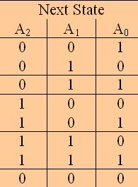
11 2-Derive state table
12 K-map for the FF output equations
13 Draw Circuit logic diagram

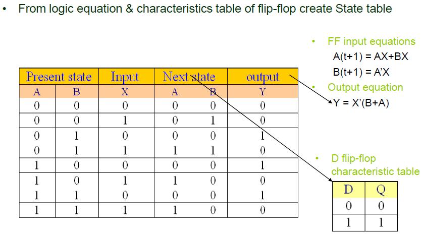
14 Analysis with D Flip Flop : Circuit, State Diagram, State Table Input Equation = DA = A ɸ x ɸ y
15 Example 1: Circuit, State Diagram, State Table
16 Example 1: State Equation A(t+1) = A(t)x(t) + B(t)x(t) B(t+1) = A (t)x(t) Y(t) = *A(t) + B(t)+x (t)
17 Example 2: Analysis with T Flip Flop Characteristic equation of T is Q(t+1) = T ɸ Q = T Q + TQ NOTE : ɸ is exclusive Output Equation will be TA = BX TB = X Y = AB
18 Example 2: Analysis with T Flip Flop
19 Types of State Machines Mealy Model for FSM Characterized by Outputs are a function of both inputs and current state Inputs Next State Logic Excitation State Memory (F/F) Current State Output Logic Outputs CLOCK
20 Types of State Machines Moore Model for FSM Characterized by Outputs are a function current state only Inputs Next State Logic Excitation State Memory (F/F) Current State Output Logic Outputs CLOCK
21 Problem : Already Discussed Analyze the following sequential circuit How to analyze any sequential circuit You need to know : State equation State diagram State table

22 Solution: 1-Determine State equation
23 Solution:2-Create State table
24 Solution :3-Construct the state diagram
25 Self Study 1. Analysis of JK Flip Flop 2. Detail study of Mealy & Moore Models
Chapter 5 Synchronous Sequential Logic
 Chapter 5 Synchronous Sequential Logic Sequential circuit: A circuit that includes memory elements. In this case the output depends not only on the current input but also on the past inputs. Memory A synchronous
Sequential Synchronous Circuit Analysis
 Sequential Synchronous Circuit Analysis General Model Current State at time (t) is stored in an array of flip-flops. Next State at time (t+1) is a Boolean function of State and Inputs. Outputs at time
Synchronous Sequential Logic
 1 IT 201 DIGITAL SYSTEMS DESIGN MODULE4 NOTES Synchronous Sequential Logic Sequential Circuits - A sequential circuit consists of a combinational circuit and a feedback through the storage elements in
Digital Logic and Design (Course Code: EE222) Lecture 19: Sequential Circuits Contd..
 Lecture 19: Sequential Circuits Contd..") Indian Institute of Technology Jodhpur, Year 2017-2018 Digital Logic and Design (Course Code: EE222) Lecture 19: Sequential Circuits Contd.. Course Instructor: Shree Prakash Tiwari Email: sptiwari@iitj.ac.in
Indian Institute of Technology Jodhpur, Year 2017-2018 Digital Logic and Design (Course Code: EE222) Lecture 19: Sequential Circuits Contd.. Course Instructor: Shree Prakash Tiwari Email: sptiwari@iitj.ac.in
Analysis and Design of Sequential Circuits: Examples
 COSC3410 Analysis and Design of Sequential Circuits: Examples J. C. Huang Department of Computer Science University of Houston Sequential machine slide 1 inputs combinational circuit outputs memory elements
COE 202: Digital Logic Design Sequential Circuits Part 3. Dr. Ahmad Almulhem ahmadsm AT kfupm Phone: Office:
 COE 202: Digital Logic Design Sequential Circuits Part 3 Dr. Ahmad Almulhem Email: ahmadsm AT kfupm Phone: 860-7554 Office: 22-324 Objectives Important Design Concepts State Reduction and Assignment Design
COE 202: Digital Logic Design Sequential Circuits Part 3. Dr. Ahmad Almulhem ahmadsm AT kfupm Phone: Office:
 COE 202: Digital Logic Design Sequential Circuits Part 3 Dr. Ahmad Almulhem Email: ahmadsm AT kfupm Phone: 860-7554 Office: 22-324 Objectives State Reduction and Assignment Design of Synchronous Sequential
Chapter 4 Part 2 Sequential Circuits
 University of Wisconsin - Madison ECE/Comp Sci 352 Digital Systems Fundamentals Kewal K. Saluja and Yu Hen Hu Spring 2002 Chapter 4 Part 2 Sequential Circuits Originals by: Charles R. Kime and Tom Kamisnski
Lecture (08) Synchronous Sequential Logic
 Synchronous Sequential Logic") Lecture (08) Synchronous Sequential Logic By: Dr. Ahmed ElShafee ١ Dr. Ahmed ElShafee, ACU : Spring 2018, CSE303 Logic design II Analysis of Clocked Sequential Circuits The behavior of a clocked sequential
Lecture (08) Synchronous Sequential Logic By: Dr. Ahmed ElShafee ١ Dr. Ahmed ElShafee, ACU : Spring 2018, CSE303 Logic design II Analysis of Clocked Sequential Circuits The behavior of a clocked sequential
Lecture 8: Sequential Networks and Finite State Machines
 Lecture 8: Sequential Networks and Finite State Machines CSE 140: Components and Design Techniques for Digital Systems Spring 2014 CK Cheng, Diba Mirza Dept. of Computer Science and Engineering University
6 Synchronous State Machine Design
 Design of synchronous counters. Based on the description of the problem, determine the required number n of the FFs - the smallest value of n is such that the number of states N 2 n and the desired counting
Synchronous Sequential Logic. Chapter 5
 Synchronous Sequential Logic Chapter 5 Other Flip Flops D flip flops requires smallest number of gates. Thus, they are commonly used Other flip flops are JK flip flops T flip flops
Lecture 10: Synchronous Sequential Circuits Design
 Lecture 0: Synchronous Sequential Circuits Design. General Form Input Combinational Flip-flops Combinational Output Circuit Circuit Clock.. Moore type has outputs dependent only on the state, e.g. ripple
3. Complete the following table of equivalent values. Use binary numbers with a sign bit and 7 bits for the value
 EGC22 Digital Logic Fundamental Additional Practice Problems. Complete the following table of equivalent values. Binary. Octal 35.77 33.23.875 29.99 27 9 64 Hexadecimal B.3 D.FD B.4C 2. Calculate the following
FSM model for sequential circuits
 1 FSM model for sequential circuits The mathematical model of a sequential circuit is called finite-state machine. FSM is fully characterized by: S Finite set of states ( state ~ contents of FFs) I Finite
Clocked Synchronous State-machine Analysis
 Clocked Synchronous State-machine Analysis Given the circuit diagram of a state machine: Analyze the combinational logic to determine flip-flop input (excitation) equations: D i = F i (Q, inputs) The input
Finite State Machine (FSM)
") Finite State Machine (FSM) Consists of: State register Stores current state Loads next state at clock edge Combinational logic Computes the next state Computes the outputs S S Next State CLK Current State
Finite State Machine (FSM) Consists of: State register Stores current state Loads next state at clock edge Combinational logic Computes the next state Computes the outputs S S Next State CLK Current State
Digital Circuits and Systems
 EE201: Digital Circuits and Systems 4 Sequential Circuits page 1 of 11 EE201: Digital Circuits and Systems Section 4 Sequential Circuits 4.1 Overview of Sequential Circuits: Definition The circuit whose
ELE2120 Digital Circuits and Systems. Tutorial Note 9
 ELE2120 Digital Circuits and Systems Tutorial Note 9 Outline 1. Exercise(1) Sequential Circuit Analysis 2. Exercise (2) Sequential Circuit Analysis 3. Exercise (3) Sequential Circuit Analysis 4. Ref. Construction
Synchronous Sequential Circuit Design. Digital Computer Design
 Synchronous Sequential Circuit Design Digital Computer Design Races and Instability Combinational logic has no cyclic paths and no races If inputs are applied to combinational logic, the outputs will always
FYSE420 DIGITAL ELECTRONICS
 FYSE42 IGITAL ELECTRONICS Lecture 4 [] [2] [3] IGITAL LOGIC CIRCUIT ANALYSIS & ESIGN Nelson, Nagle, Irvin, Carrol ISBN -3-463894-8 IGITAL ESIGN Morris Mano Fourth edition ISBN -3-98924-3 igital esign Principles
Sequential Circuit Analysis
 Sequential Circuit Analysis Last time we started talking about latches and flip-flops, which are basic one-bit memory units. Today we ll talk about sequential circuit analysis and design. First, we ll
UNIVERSITY OF BOLTON SCHOOL OF ENGINEERING BENG (HONS) ELECTRICAL & ELECTRONICS ENGINEERING EXAMINATION SEMESTER /2017
 ELECTRICAL & ELECTRONICS ENGINEERING EXAMINATION SEMESTER /2017") UNIVERSITY OF BOLTON TW35 SCHOOL OF ENGINEERING BENG (HONS) ELECTRICAL & ELECTRONICS ENGINEERING EXAMINATION SEMESTER 2-2016/2017 INTERMEDIATE DIGITAL ELECTRONICS AND COMMUNICATIONS MODULE NO: EEE5002
UNIVERSITY OF BOLTON TW35 SCHOOL OF ENGINEERING BENG (HONS) ELECTRICAL & ELECTRONICS ENGINEERING EXAMINATION SEMESTER 2-2016/2017 INTERMEDIATE DIGITAL ELECTRONICS AND COMMUNICATIONS MODULE NO: EEE5002
Synchronous Sequential Logic Part I. BME208 Logic Circuits Yalçın İŞLER
 Synchronous Sequential Logic Part I BME28 Logic Circuits Yalçın İŞLER islerya@yahoo.com http://me.islerya.com Sequential Logic Digital circuits we have learned, so far, have been combinational no memory,
The Design Procedure. Output Equation Determination - Derive output equations from the state table
 The Design Procedure Specification Formulation - Obtain a state diagram or state table State Assignment - Assign binary codes to the states Flip-Flop Input Equation Determination - Select flipflop types
CprE 281: Digital Logic
 CprE 281: Digital Logic Instructor: Alexander Stoytchev http://www.ece.iastate.edu/~alexs/classes/ Synchronous Sequential Circuits Basic Design Steps CprE 281: Digital Logic Iowa State University, Ames,
Sequential logic and design
 Principles Of Digital Design Sequential logic and design Analysis State-based (Moore) Input-based (Mealy) FSM definition Synthesis State minimization Encoding Optimization and timing Copyright 20-20by
ECEN 248: INTRODUCTION TO DIGITAL SYSTEMS DESIGN. Week 7 Dr. Srinivas Shakkottai Dept. of Electrical and Computer Engineering
 ECEN 248: INTRODUCTION TO DIGITAL SYSTEMS DESIGN Week 7 Dr. Srinivas Shakkottai Dept. of Electrical and Computer Engineering SEQUENTIAL CIRCUITS: LATCHES Overview Circuits require memory to store intermediate
Appendix B. Review of Digital Logic. Baback Izadi Division of Engineering Programs
 Appendix B Review of Digital Logic Baback Izadi Division of Engineering Programs bai@engr.newpaltz.edu Elect. & Comp. Eng. 2 DeMorgan Symbols NAND (A.B) = A +B NOR (A+B) = A.B AND A.B = A.B = (A +B ) OR
Logical design of digital systems
 21062017 lectures Summer Semester 2017 Table of content 1 Combinational circuit design 2 Elementary combinatorial circuits for data transmission 3 Memory structures 4 Programmable logic devices 5 Algorithmic
Lecture 17: Designing Sequential Systems Using Flip Flops
 EE210: Switching Systems Lecture 17: Designing Sequential Systems Using Flip Flops Prof. YingLi Tian April 11, 2019 Department of Electrical Engineering The City College of New York The City University
Clocked Sequential Circuits UNIT 13 ANALYSIS OF CLOCKED SEQUENTIAL CIRCUITS. Analysis of Clocked Sequential Circuits. Signal Tracing and Timing Charts
 ed Sequential Circuits 2 Contents nalysis by signal tracing & timing charts State tables and graphs General models for sequential circuits sequential parity checker Reading Unit 3 asic unit Unit : Latch
Chapter 7. Synchronous Sequential Networks. Excitation for
 Chapter 7 Excitation for Synchronous Sequential Networks J. C. Huang, 2004 igital Logic esign 1 Structure of a clocked synchronous sequential network Mealy model of a clocked synchronous sequential network
Synchronous Sequential Logic Part I
 Synchronous Sequential Logic Part I Mantıksal Tasarım BBM23 section instructor: Ufuk Çelikcan Sequential Logic Digital circuits we have learned, so far, have been combinational no memory, outputs are entirely
Fundamentals of Digital Design
 Fundamentals of Digital Design Digital Radiation Measurement and Spectroscopy NE/RHP 537 1 Binary Number System The binary numeral system, or base-2 number system, is a numeral system that represents numeric
CSE140: Digital Logic Design Registers and Counters
 CSE14: Digital Logic Design Registers and Counters Prof. Tajana Simunic Rosing 38 Where we are now. What we covered last time: ALUs, SR Latch Latches and FlipFlops (FFs) Registers What we ll do next FSMs
Different encodings generate different circuits
 FSM State Encoding Different encodings generate different circuits no easy way to find best encoding with fewest logic gates or shortest propagation delay. Binary encoding: K states need log 2 K bits i.e.,
Lecture 3 Review on Digital Logic (Part 2)
") Lecture 3 Review on Digital Logic (Part 2) Xuan Silvia Zhang Washington University in St. Louis http://classes.engineering.wustl.edu/ese461/ ircuit Optimization Simplest implementation ost criterion literal
Lecture 3 Review on Digital Logic (Part 2) Xuan Silvia Zhang Washington University in St. Louis http://classes.engineering.wustl.edu/ese461/ ircuit Optimization Simplest implementation ost criterion literal
ECE380 Digital Logic. Synchronous sequential circuits
 ECE38 Digital Logic Synchronous Sequential Circuits: State Diagrams, State Tables Dr. D. J. Jackson Lecture 27- Synchronous sequential circuits Circuits here a clock signal is used to control operation
Models for representing sequential circuits
 Sequential Circuits Models for representing sequential circuits Finite-state machines (Moore and Mealy) Representation of memory (states) Changes in state (transitions) Design procedure State diagrams
Chapter 15 SEQUENTIAL CIRCUITS ANALYSIS, STATE- MINIMIZATION, ASSIGNMENT AND CIRCUIT IMPLEMENTATION
 Chapter 15 SEQUENTIAL CIRCUITS ANALYSIS, STATE- MINIMIZATION, ASSIGNMENT AND CIRCUIT IMPLEMENTATION Lesson 2 ANALYSIS OF CLOCKED SEQUENTIAL CIRCUIT Ch15L2- "Digital Principles and Design", Raj Kamal, Pearson
Digital Logic Design - Chapter 5
 Digital Logic Design - Chapter 5 S. Design a 2-bit binary up counter a) using positive-edge-triggered D flip-flops. b) using positive-edge-triggered T flip-flops. c) using positive-edge-triggered JK flip-flops.
ENGG 1203 Tutorial _03 Laboratory 3 Build a ball counter. Lab 3. Lab 3 Gate Timing. Lab 3 Steps in designing a State Machine. Timing diagram of a DFF
 ENGG 1203 Tutorial _03 Laboratory 3 Build a ball counter Timing diagram of a DFF Lab 3 Gate Timing difference timing for difference kind of gate, cost dependence (1) Setup Time = t2-t1 (2) Propagation
King Fahd University of Petroleum and Minerals College of Computer Science and Engineering Computer Engineering Department
 King Fahd University of Petroleum and Minerals College of Computer Science and Engineering Computer Engineering Department Page 1 of 13 COE 202: Digital Logic Design (3-0-3) Term 112 (Spring 2012) Final
CSE 140: Components and Design Techniques for Digital Systems. Lecture 9: Sequential Networks: Implementation
 CSE 4: Components and Design Techniques for Digital Systems Lecture 9: Sequential Networks: Implementation CK Cheng Dept. of Computer Science and Engineering University of California, San Diego Implementation
Counters. We ll look at different kinds of counters and discuss how to build them
 Counters We ll look at different kinds of counters and discuss how to build them These are not only examples of sequential analysis and design, but also real devices used in larger circuits 1 Introducing
Sequential Circuits Sequential circuits combinational circuits state gate delay
 Sequential Circuits Sequential circuits are those with memory, also called feedback. In this, they differ from combinational circuits, which have no memory. The stable output of a combinational circuit
EGR224 F 18 Assignment #4
 EGR224 F 18 Assignment #4 ------------------------------------------------------------------------------------------------------------- Due Date: Friday (Section 10), October 19, by 5 pm (slide it under
Chapter 5 Synchronous Sequential Logic
 Chapter 5 Synchronous Sequential Logic Sequential Circuits Latches and Flip Flops Analysis of Clocked Sequential Circuits HDL Optimization Design Procedure Sequential Circuits Various definitions Combinational
or 0101 Machine
 Synchronous State Graph or Synchronous State Graph or Detector Design a state graph for a machine with: One input X, one output Z. Z= after receiving the complete sequence or Overlapped sequences are detected.
Digital Logic Design - Chapter 4
 Digital Logic Design - Chapter 4 1. Analyze the latch circuit shown below by obtaining timing diagram for the circuit; include propagation delays. Y This circuit has two external input and one feedback
Sequential Circuit Design
 Sequential Circuit esign esign Procedure. Specification 2. Formulation Obtain a state diagram or state table 3. State Assignment Assign binary codes to the states 4. Flip-Flop Input Equation etermination
CE1911 LECTURE FSM DESIGN PRACTICE DAY 1
 REVIEW MATERIAL 1. Combinational circuits do not have memory. They calculate instantaneous outputs based only on current inputs. They implement basic arithmetic and logic functions. 2. Sequential circuits
Chapter 6. Synchronous Sequential Circuits
 Chapter 6 Synchronous Sequential Circuits In a combinational circuit, the values of the outputs are determined solely by the present values of its inputs. In a sequential circuit, the values of the outputs
Overview of Chapter 4
 Overview of hapter 4 Types of Sequential ircuits Storage Elements Latches Flip-Flops Sequential ircuit Analysis State Tables State Diagrams Sequential ircuit Design Specification Assignment of State odes
EEE2135 Digital Logic Design
 EEE2135 Digital Logic Design Chapter 7. Sequential Circuits Design 서강대학교 전자공학과 1. Model of Sequential Circuits 1) Sequential vs. Combinational Circuits a. Sequential circuits: Outputs depend on both the
Sequential Logic Circuits
 Chapter 4 Sequential Logic Circuits 4 1 The defining characteristic of a combinational circuit is that its output depends only on the current inputs applied to the circuit. The output of a sequential circuit,
Homework #4. CSE 140 Summer Session Instructor: Mohsen Imani. Only a subset of questions will be graded
 Homework #4 CSE 140 Summer Session 2 2017 Instructor: Mohsen Imani Only a subset of questions will be graded 1) For the circuit shown below, do the following: a. Write a logic equation for the output P
10/12/2016. An FSM with No Inputs Moves from State to State. ECE 120: Introduction to Computing. Eventually, the States Form a Loop
 University of Illinois at Urbana-Champaign Dept. of Electrical and Computer Engineering An FSM with No Inputs Moves from State to State What happens if an FSM has no inputs? ECE 120: Introduction to Computing
EECS Components and Design Techniques for Digital Systems. FSMs 9/11/2007
 EECS 150 - Components and Design Techniques for Digital Systems FSMs 9/11/2007 Sarah Bird Electrical Engineering and Computer Sciences University of California, Berkeley Slides borrowed from David Culler
CS221: Digital Design. Dr. A. Sahu. Indian Institute of Technology Guwahati
 CS221: Digital Design Counter&Registers Dr. A. Sahu DeptofComp.Sc.&Engg. Indian Institute of Technology Guwahati Outline Counter : Synchronous Vs Asynchronous Counter: Finite it State t Machine Mhi A register
Synchronous Sequential Circuit Design
 Synchronous Sequential Circuit Design 1 Sequential circuit design In sequential circuit design, we turn some description into a working circuit We first make a state table or diagram to express the computation
11.1 As mentioned in Experiment 10, sequential logic circuits are a type of logic circuit where the output of
 EE 2449 Experiment 11 Jack Levine and Nancy Warter-Perez CALIFORNIA STATE UNIVERSITY LOS ANGELES Department of Electrical and Computer Engineering EE-2449 Digital Logic Lab EXPERIMENT 11 SEQUENTIAL CIRCUITS
Analysis of clocked sequential networks
 Analysis of clocked sequential networks keywords: Mealy, Moore Consider : a sequential parity checker an 8th bit is added to each group of 7 bits such that the total # of 1 bits is odd for odd parity if
Digital Design. Sequential Logic
 Principles Of igital esign Chapter 6 Sequential Logic Chapter preview Boolean algebra 3 Logic gates and flip-flops 3 Finite-state machine 6 Logic design techniques 4 Sequential design techniques 6 Binary
King Fahd University of Petroleum and Minerals College of Computer Science and Engineering Computer Engineering Department
 King Fahd University of Petroleum and Minerals College of Computer Science and Engineering Computer Engineering Department Page of COE 22: Digital Logic Design (3--3) Term (Fall 22) Final Exam Sunday January
Chapter 4. Sequential Logic Circuits
 Chapter 4 Sequential Logic Circuits 1 2 Chapter 4 4 1 The defining characteristic of a combinational circuit is that its output depends only on the current inputs applied to the circuit. The output of
Q: Examine the relationship between X and the Next state. How would you describe this circuit? A: An inverter which is synched with a clock signal.
 /2/2 OF 7 Next, let s reverse engineer a T-Flip flop Prob. (Pg 529) Note that whenever T is equal to, there is a state change, otherwise, there isn t. In this circuit, (x) determines whether the output
ELCT201: DIGITAL LOGIC DESIGN
 ELCT201: DIGITAL LOGIC DESIGN Dr. Eng. Haitham Omran, haitham.omran@guc.edu.eg Dr. Eng. Wassim Alexan, wassim.joseph@guc.edu.eg Following the slides of Dr. Ahmed H. Madian Lecture 10 محرم 1439 ه Winter
Digital Design 2010 DE2 1
 1 Underviser: D. M. Akbar Hussain Litteratur: Digital Design Principles & Practices 4 th Edition by yj John F. Wakerly 2 DE2 1 3 4 DE2 2 To enable students to apply analysis, synthesis and implementation
EECS150 - Digital Design Lecture 23 - FSMs & Counters
 EECS150 - Digital Design Lecture 23 - FSMs & Counters April 8, 2010 John Wawrzynek Spring 2010 EECS150 - Lec22-counters Page 1 One-hot encoding of states. One FF per state. State Encoding Why one-hot encoding?
CSCI 2150 Intro to State Machines
 CSCI 2150 Intro to State Machines Topic: Now that we've created flip-flops, let's make stuff with them Reading: igital Fundamentals sections 6.11 and 9.4 (ignore the JK flip-flop stuff) States Up until
CPE100: Digital Logic Design I
 Professor Brendan Morris, SEB 3216, brendan.morris@unlv.edu CPE100: Digital Logic Design I Midterm02 Review http://www.ee.unlv.edu/~b1morris/cpe100/ 2 Logistics Thursday Nov. 16 th In normal lecture (13:00-14:15)
Lecture 14: State Tables, Diagrams, Latches, and Flip Flop
 EE210: Switching Systems Lecture 14: State Tables, Diagrams, Latches, and Flip Flop Prof. YingLi Tian Nov. 6, 2017 Department of Electrical Engineering The City College of New York The City University
Introduction EE 224: INTRODUCTION TO DIGITAL CIRCUITS & COMPUTER DESIGN. Lecture 6: Sequential Logic 3 Registers & Counters 5/9/2010
 EE 224: INTROUCTION TO IGITAL CIRCUITS & COMPUTER ESIGN Lecture 6: Sequential Logic 3 Registers & Counters 05/10/2010 Avinash Kodi, kodi@ohio.edu Introduction 2 A Flip-Flop stores one bit of information
Timing Constraints in Sequential Designs. 63 Sources: TSR, Katz, Boriello & Vahid
 Timing Constraints in Sequential esigns 63 Sources: TSR, Katz, Boriello & Vahid Where we are now. What we covered last time: FSMs What we ll do next: Timing constraints Upcoming deadlines: ZyBook today:
Topic 8: Sequential Circuits
 Topic 8: Sequential Circuits Readings : Patterson & Hennesy, Appendix B.4 - B.6 Goals Basic Principles behind Memory Elements Clocks Applications of sequential circuits Introduction to the concept of the
Synchronous Sequential Circuit Design. Dr. Ehab A. H. AL-Hialy Page 1
 Synchronous Sequential Circuit Design Dr. Ehab A. H. AL-Hialy Page Motivation Analysis of a few simple circuits Generalizes to Synchronous Sequential Circuits (SSC) Outputs are Function of State (and Inputs)
Philadelphia University Student Name: Student Number:
 Philadelphia University Student Name: Student Number: Faculty of Engineering Serial Number: Final Exam, Second Semester: 2015/2016 Dept. of Computer Engineering Course Title: Logic Circuits Date: 08/06/2016
Ch 7. Finite State Machines. VII - Finite State Machines Contemporary Logic Design 1
 Ch 7. Finite State Machines VII - Finite State Machines Contemporary Logic esign 1 Finite State Machines Sequential circuits primitive sequential elements combinational logic Models for representing sequential
ECEN 248: INTRODUCTION TO DIGITAL SYSTEMS DESIGN. Week 9 Dr. Srinivas Shakkottai Dept. of Electrical and Computer Engineering
 ECEN 248: INTRODUCTION TO DIGITAL SYSTEMS DESIGN Week 9 Dr. Srinivas Shakkottai Dept. of Electrical and Computer Engineering TIMING ANALYSIS Overview Circuits do not respond instantaneously to input changes
ELEC Digital Logic Circuits Fall 2014 Sequential Circuits (Chapter 6) Finite State Machines (Ch. 7-10)
 Finite State Machines (Ch. 7-10)") ELEC 2200-002 Digital Logic Circuits Fall 2014 Sequential Circuits (Chapter 6) Finite State Machines (Ch. 7-10) Vishwani D. Agrawal James J. Danaher Professor Department of Electrical and Computer Engineering
ELEC 2200-002 Digital Logic Circuits Fall 2014 Sequential Circuits (Chapter 6) Finite State Machines (Ch. 7-10) Vishwani D. Agrawal James J. Danaher Professor Department of Electrical and Computer Engineering
Chapter 6 Introduction to state machines
 9..7 hapter 6 Introduction to state machines Dr.-Ing. Stefan Werner Table of content hapter : Switching Algebra hapter : Logical Levels, Timing & Delays hapter 3: Karnaugh-Veitch-Maps hapter 4: ombinational
Mealy & Moore Machines
 Mealy & Moore Machines Moore Machine is a finite-state machine whose output values are determined solely by its current state and can be defined as six elements (S, S 0, Σ, Λ, T, G), consisting of the
EE 209 Logic Cumulative Exam Name:
 EE 209 Logic Cumulative Exam Name: 1.) Answer the following questions as True or False a.) A 4-to-1 multiplexer requires at least 4 select lines: true / false b.) An 8-to-1 mux and no other logi can be
14:332:231 DIGITAL LOGIC DESIGN
 14:332:231 IGITL LOGI ESIGN Ivan Marsic, Rutgers University Electrical & omputer Engineering all 2013 Lecture #17: locked Synchronous -Machine nalysis locked Synchronous Sequential ircuits lso known as
EECS150 - Digital Design Lecture 17 - Sequential Circuits 3 (Counters)
") EECS150 - Digital Design Lecture 17 - Sequential Circuits 3 (Counters) March 19&21, 2002 John Wawrzynek Spring 2002 EECS150 - Lec13-seq3 version 2 Page 1 Counters Special sequential circuits (FSMs) that
EECS150 - Digital Design Lecture 17 - Sequential Circuits 3 (Counters) March 19&21, 2002 John Wawrzynek Spring 2002 EECS150 - Lec13-seq3 version 2 Page 1 Counters Special sequential circuits (FSMs) that
Sequential Logic. Rab Nawaz Khan Jadoon DCS. Lecturer COMSATS Lahore Pakistan. Department of Computer Science
 Sequential Logic Rab Nawaz Khan Jadoon DCS COMSATS Institute of Information Technology Lecturer COMSATS Lahore Pakistan Digital Logic and Computer Design Sequential Logic Combinational circuits with memory
CSE140: Components and Design Techniques for Digital Systems. Midterm Information. Instructor: Mohsen Imani. Sources: TSR, Katz, Boriello & Vahid
 CSE140: Components and Design Techniques for Digital Systems Midterm Information Instructor: Mohsen Imani Midterm Topics In general: everything that was covered in homework 1 and 2 and related lectures,
Present Next state Output state w = 0 w = 1 z A A B 0 B A C 0 C A C 1
 W Combinational circuit Flip-flops Combinational circuit Z cycle: t t t 2 t 3 t 4 t 5 t 6 t 7 t 8 t 9 t : : Figure 8.. The general form of a sequential circuit. Figure 8.2. Sequences of input and output
Digital Logic Design. Midterm #2
 EECS: igital Logic esign r. nthony. Johnson s7m2s_dild7.fm - igital Logic esign Midterm #2 Problems Points. 5 2. 4 3. 6 Total 5 Was the exam fair? yes no EECS: igital Logic esign r. nthony. Johnson s7m2s_dild7.fm
ENGG 1203 Tutorial. Solution (b) Solution (a) Simplification using K-map. Combinational Logic (II) and Sequential Logic (I) 8 Feb Learning Objectives
 Solution (a) Simplification using K-map. Combinational Logic (II) and Sequential Logic (I) 8 Feb Learning Objectives") ENGG 23 Tutorial Simplification using K-map Combinational Logic (II) and Sequential Logic (I) 8 Feb Learning Objectives Apply Karnaugh map for logic simplification Design a finite state machine News HW
ENGG 23 Tutorial Simplification using K-map Combinational Logic (II) and Sequential Logic (I) 8 Feb Learning Objectives Apply Karnaugh map for logic simplification Design a finite state machine News HW
ECE 341. Lecture # 3
 ECE 341 Lecture # 3 Instructor: Zeshan Chishti zeshan@ece.pdx.edu October 7, 2013 Portland State University Lecture Topics Counters Finite State Machines Decoders Multiplexers Reference: Appendix A of
Review for B33DV2-Digital Design. Digital Design
 Review for B33DV2 The Elements of Modern Behaviours Design Representations Blocks Waveforms Gates Truth Tables Boolean Algebra Switches Rapid Prototyping Technologies Circuit Technologies TTL MOS Simulation
14.1. Unit 14. State Machine Design
 4. Unit 4 State Machine Design 4.2 Outcomes I can create a state diagram to solve a sequential problem I can implement a working state machine given a state diagram STATE MACHINES OVERVIEW 4.3 4.4 Review
Lecture 13: Sequential Circuits, FSM
 Lecture 13: Sequential Circuits, FSM Today s topics: Sequential circuits Finite state machines Reminder: midterm on Tue 2/28 will cover Chapters 1-3, App A, B if you understand all slides, assignments,
ALU, Latches and Flip-Flops
 CSE14: Components and Design Techniques for Digital Systems ALU, Latches and Flip-Flops Tajana Simunic Rosing Where we are. Last time: ALUs Plan for today: ALU example, latches and flip flops Exam #1 grades
Design of Sequential Circuits
 Design of Sequential Circuits Seven Steps: Construct a state diagram (showing contents of flip flop and inputs with next state) Assign letter variables to each flip flop and each input and output variable
EE40 Lec 15. Logic Synthesis and Sequential Logic Circuits
 EE40 Lec 15 Logic Synthesis and Sequential Logic Circuits Prof. Nathan Cheung 10/20/2009 Reading: Hambley Chapters 7.4-7.6 Karnaugh Maps: Read following before reading textbook http://www.facstaff.bucknell.edu/mastascu/elessonshtml/logic/logic3.html
 vidyarthiplus.com vidyarthiplus.com vidyarthiplus.com ANNA UNIVERSITY- COMBATORE B.E./ B.TECH. DEGREE EXAMINATION - JUNE 2009. ELECTRICAL & ELECTONICS ENGG. - FOURTH SEMESTER DIGITAL LOGIC CIRCUITS PART-A