Water Flow in Open Channels
|
|
|
- Kristopher Dalton
- 6 years ago
- Views:
Transcription

1 The Islamic Universit of Gaza Facult of Engineering Civil Engineering Department Hdraulics - ECIV 33 Chapter 6 Water Flow in Open Channels
2 Introduction An open channel is a duct in which the liquid flows with a free surface. Open channel hdraulics is of great importance in civil engineers, it deals with flows having a free surface, for example: Channels constructed for water suppl, irrigation, drainage, and Sewers, culverts, and Tunnels flowing partiall full; and Natural streams and rivers.
3 Pipe Flow and Open Channel Flow Pipe Flow The liquid completel fills the pipe and flow under pressure. The flow in a pipe takes place due to difference of pressure (pressure gradient), The flow in a closed conduit is not necessaril a pipe flow. Open Channel Flow Flow takes place due to the slope of the channel bed (due to gravit). The flow must be classified as open channel flow if the liquid has a free surface. 3
4 Pipe Flow Open Channel Flow 4
5 For Pipe flow (Fig. a): The hdraulic gradient line (HGL) is the sum of the elevation and the pressure head (connecting the water surfaces in piezometers). The energ gradient line (EGL) is the sum of the HGL and velocit head. The amount of energ loss when the liquid flows from section to section is indicated b h L. For open channel flow (Fig. b): The hdraulic gradient line (HGL) corresponds to the water surface line (WSL); where it subjected to onl atmospheric pressure which is commonl referred to as the zero pressure reference. The energ gradient line (EGL) is the sum of the HGL and velocit head. The amount of energ loss when the liquid flows from section to section is indicated b h L. For uniform flow in an open channel, this drop in the EGL is equal to the drop in the channel bed. 5
6 6. Classifications of Open Channel Flow Classification based on the time criterion:. Stead Flow (time independent) (discharge and water depth do not change with time). Unstead Flow (time dependent) (discharge and water depth at an section change with time) Classification based on the space criterion:. Uniform flow (are mostl stead) (discharge and water depth remains the same at ever section in the channel). Non-uniform Flow (discharge and water depth change at an section in the channel) 6
7 Non-uniform flow is also called varied flow ( the flow in which the water depth and or discharge change along the length of the channel), it can be further classified as: Graduall varied flow (GVF) where the depth of the flow changes graduall along the length of the channel. Rapidl varied flow (RVF) where the depth of flow changes suddenl over a small length of the channel. 7
8 a) Uniform flow are mostl stead b) Unstead uniform flows are ver rare in nature c) Stead varied flow (over a spillwa crest) d) Unstead varied flow (flood wave) e) Unstead varied flow (tidal surge) 8
9 9
10 6. Uniform Flow in Open Channel Uniform flow in an open channel must satisf the following main features:. The water depth, flow area A, discharge Q, and the velocit distribution V at all sections throughout the entire channel length must remain constant.. The slope of the energ gradient line (S e ), the water surface slope (S ws ), and the channel bed slope (S 0 ) are equal. S e S ws S 0 0
11 This is possible when the gravit force (W sin θ) component equal the resistance to the flow (F f ) W sinθ + F F Hdrostati c forces at ends sinθ W sinθ F τ 0 f K cns tan t of proportion alit γals F tanθ F S ( γal)sinθ γals τ PL ( KV 0 0 F f ) PL 0 resisting force per unit area of channel, γ A ( KV ) PL V. S K P V C R S h e C γ Chez cons tant R h HdraulicRadius K A P The Chez Formula
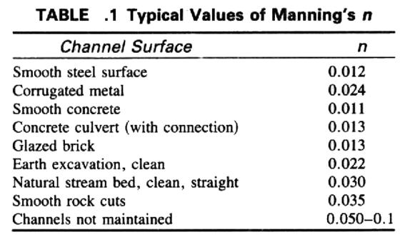
12 R h hdraulic radius or hdraulic mean depth area of flow ( wetted area ) R h wetted perimeter C Chez coefficient (Chez s resistance factor), m / /s, varies in relation of both the conditions of channel and flow. Manning derived the following empirical relation: A P C n R / 6 h where n Manning s coefficient for the channel roughness See the next table for tpical values of n.
13 3
14 Manning s formula Substituting into Chez equation, we obtain the Manning s formula for uniform flow: V n / 3 /3 R h S e OR Q VA A R h Se n Where: Q in m 3 /sec, V in m/sec, R h in m, S e in (m/m), n is dimensionless 4
15 Example Open channel of width 3m as shown, bed slope :5000, d.5m find the flow rate using Manning equation, n0.05. V Rh n A 0.5 P 3 S e ( 3 + 9) ( ) m m.5m A 9 Rh P V Q VA m 3 / m/s s 5
16 Example The cross section of an open channel is a trapezoid with a bottom width of 4 m and side slopes :, calculate the discharge if the depth of water is.5 m and bed slope /600. Take Chez constant C 50. 6
17 Example Open channel as shown, bed slope 69:584, find the flow rate using Chez equation, take C35. 7
18 8 ( ) ( ) s VA Q V P A R P A R S C V h e h / 3.84 m m/s m m
19 6.3 Hdraulic Efficienc of open channel sections Based on their existence, an open channel can be natural or artificial: Natural channels: such as streams, rivers, valles, etc. These are generall irregular in shape, alignment and roughness of the surface. Artificial channels: built for some specific purpose, such as irrigation, water suppl, wastewater, water power development, and rain collection channels. These are regular in shape and alignment with uniform roughness of the boundar surface. 9
 change, the channel is referred to as non-prismatic. It is obvious that onl artificial channel can be prismatic.")
20 Based on their shape, an open channel can be prismatic or nonprismatic: Prismatic channels: the cross section is uniform and the bed slop is constant. Non-prismatic channels: when either the cross section or the slope (or both) change, the channel is referred to as non-prismatic. It is obvious that onl artificial channel can be prismatic. The most common shapes of prismatic channels are rectangular, parabolic, triangular, trapezoidal and circular; see the next figure. 0
21 Most common shapes of prismatic channels
22 Most economical section is called the best hdraulic section or most efficient section as the discharge, passing through a given cross-sectional area A, slope of the bed S 0 and a resistance coefficient, is maximum. Hence the discharge Q will be maximum when the wetted perimeter P is minimum. Q AV AC R h S e AC A S P e const.* P
23 Economical Rectangular Channel A B D, P D + B A P D + D P should be minimum for a given area; dp dd A A 0 D D A B D D D R h 4 P B+ D D+ D dp 0 dd BD D D D R h B D D D B So, the rectangular channel will be most economical when either: the depth of the flow is half the width, or the hdraulic radius is half the depth of flow. 3
24 A (B + nd )D Economical Trapezoidal Channel P B+ D + n B A P ( nd ) + D + n D dp dd 0 A D nd dp A n+ + n 0 dd D (B+ nd)d B nd + n + n + D D or P B + B + n D ( B + n D ) D A + n D B+ nd + n + n A Rh P ( B + n D ) D ( B + n D ) D Rh 4
25 Other criteria for economic Trapezoidal section When a semi-circle is drawn with the trapezoidal center, O, on the water surface and radius equal to the depth of flow, D, the three sides of the channel are tangential to the semi-circle. To prove this condition, using the figure shown, we have: B OF OM sin α ( B + n D ) sin α ( + n D ) sin α OF sinα B + n D using triangle KMN, we have: MK sinα MN D D + n 5
26 OF ( B ) + n D + n B + n D using equation D + n to replace the numerator, we obtain: OF D + + n n OF D Thus, if a semi-circle is drawn with O as center and radius equal to the depth of flow D, the three sides of a most economical trapezoidal section will be tangential to the semicircle. 6
27 The best side slope for Trapezoidal section when n 3 θ 60 ο D P + n B+ n D B D ( + n n) B + B + n D ( B + n D ) A D n D D + n ( n ) D A + n n B A D n D 7
28 Now, from equations: P ( B + n D) B A P D n D A D squaring both sides dp dn n + n 0 A P 4( ) 4 A( + n n) D P dp 4 A [( + n ) *( n) ] dn 4n + n n 3 3 n tanθ θ ο 60 The best side slope is at 60 o to the horizontal, i.e.; of all trapezoidal sections a half hexagon is most economical. However, because of constructional difficulties, it ma not be practical to adopt the most economical side slopes 8
29 αd A 4 d 8 P α r αd sinα Circular section In the case of circular channels, the area of the flow cannot be maintained constant. Indeed, the cross-sectional area A and the wetted perimeter P both do not depend on D but the depend on the angle α. Referring to the figure shown, we can determine the wetted perimeter P and the area of flow A as follows: Thus in case of circular channels, for most economical section, two separate conditions are obtained:. Condition for maximum discharge, and. Condition for maximum velocit. 9
30 . Condition for Maximum Discharge for Circular Section: Q AV AC R S C A 3 h P S Q C S A P 3 dq dα 0 (Using the Chez formula) α ο 54 D d (Using Manning s formula) α ο 5 D d. Condition for Maximum Velocit for Circular Section: V C R S C A h P S V C S α ο. D d A P dv dα 0 30
31 Variation of flow and velocit with depth in circular pipes 3
32 6.4 Energ Principle in Open Channel Flow The total energ of a flowing liquid per unit weight is given b: Total Energ Z + + V g If the channel bed is taken as the datum, then the total energ per unit weight will be: V E specific + g Specific energ (Es) of a flowing liquid in a channel is defined as energ per unit weight of the liquid measured from the channel bed as datum. It is a ver useful concept in the stud of open channel flow. 3
33 E V + E + g E s p k Es + Q g A E p potential energ of flow E k kinetic energ of flow Valid for an cross section V g Specific Energ Curve: It is defined as the curve which shows the variation of specific energ (Es ) with depth of flow. 33
34 Specific Energ Curve (Rectangular channel) Consider a rectangular channel in which a constant discharge Q q discharge per unit width constant ( since Q and B are constants) V Q A Q B q B q E + E + s p g E p E k E K E P E s c 34
35 Sub-critical, critical, and supercritical flow The criterion used in this classification is what is known b Froude number, Fr, which is the measure of the relative effects of inertia forces to gravit force: F r V gd h Q T A g F r 3 T V mean velocit of flow of water, D h hdraulic depth of the channel D h Area of Flow (Wetted Area) Water Surface Width A T T Fr Fr < Fr Fr > Flow Sub-critical Critical Supercritical 35
36 Referring to the energ curve, the following features can be observed:. The depth of flow at point C is referred to as critical depth, c. (It is defined as that depth of flow of liquid at which the specific energ is E min c minimum, The flow that corresponds to this point is called critical flow (Fr.0).. For values of E s greater than E min, there are two corresponding depths. One depth is greater than the critical depth and the other is smaller then the critical depth, for example; E and ' s These two depths for a given specific energ are called the alternate depths. 3. If the flow depth > c the flow is said to be sub-critical (Fr <.0). In this case E s increases as increases. 4. If the flow depth < c the flow is said to be super-critical (Fr >.0). In this case E s decreases as increases. 36
37 37
38 de d Critical depth, c for rectangular channel Critical depth, c, is defined as that depth of flow of liquid at which the specific energ is minimum, E min, The mathematical expression for critical depth is obtained b differentiating energ equation with respect to and equating the result to zero; E s + q g d 0 d q g ( q q g ) g ( ) q g q c g
39 39 Critical velocit, V c for rectangular channel, 3 g q c q B Q A Q V V q c c OR g V c c c 3 V g c c r c c F g V
40 Minimum Specific Energ in terms of critical depth Emin c + 3 c q g q g c Emin c + c c Emin 3 OR E c 3 min 40
41 Critical depth, c, for Non- Rectangular Channels de d Q Q da s 0 ( + ) ( ) d 0 3 d g A g A d Q da OR ( ) 0 3 g A d (constant discharge is assumed) da/d the rate of increase of area with respect to T (top width). Q T 0 g A 3 Recalling that D h Q g A T 3 A condition must be satisfied for the flow at the critical depth. Q g T A D h The equation ma also be written in terms of velocit V g D h The velocit head is equal to one-half the hdraulic depth for critical flow. 4
42 Q A E s + E s + This equation represents g A T the critical state OR E c A c + ( T ) The general equation for the specific energ in critical state applicable to channels of all shapes. Rectangular section Trapezoidal section E c 3 c E c ( 3B + 5n ) c ( B + n ) c c Circular section Triangle section d d Ec ( + cos α ) 6 ( α sin α ) sinα E c 5 4 c 4
43 Constant Specific Energ The specific energ was varied and the discharge was assumed to be constant. Let us now consider the case in which the specific energ is kept constant and the discharge Q is varied. Q E s Q A g E s g A ( ) s s Q A ( g) ( E ) ga E ga The discharge will maximum if dq d 0 Q dq d g E A da g A da s( ) ( + A ) d d da/d T ge ( AT ) g ( AT ) ga 0 s 43
44 4EsT 4T A 0 T ( E s ) A E A s + T but Es + Q + g A Q g A A + T Q g 3 A T Thus for a given specific energ, the discharge in a given channel is a maximum when the flow is in the critical state. The depth corresponding to the maximum discharge is the critical depth. 44
45 6.5 Hdraulic Jump A hdraulic jump occurs when flow changes from a supercritical flow (unstable) to a sub-critical flow (stable). There is a sudden rise in water level at the point where the hdraulic jump occurs. Rollers (eddies) of turbulent water form at this point. These rollers cause dissipation of energ. A hdraulic jump occurs in practice at the toe of a dam or below a sluice gate where the velocit is ver high. 45
46 General Expression for Hdraulic Jump: In the analsis of hdraulic jumps, the following assumptions are made: () The length of hdraulic jump is small. Consequentl, the loss of head due to friction is negligible. () The flow is uniform and pressure distribution is due to hdrostatic before and after the jump. (3) The slope of the bed of the channel is ver small, so that the component of the weight of the fluid in the direction of the flow is neglected. 46

47 Location of hdraulic jump Generall, a hdraulic jump occurs when the flow changes from supercritical to subcritical flow. The most tpical cases for the location of hdraulic jump are:. Jump below a sluice gate.. Jump at the toe of a spillwa. 3. Jump at a glacis. (glacis is the name given to sloping floors provided in hdraulic structures.) 47
48 The net force in the direction of flow the rate of change of moment in that direction Q γ g ( V V ) The net force in the direction of the flow, neglecting frictional resistance and the component of weight of water in the direction of flow, R F - F. Therefore, the impulse-moment ields F γ Q F ( V V ) g Where F and F are the pressure forces at section and, respectivel. γ A γ A Q ga γ Q γ A ( V V ) g γ Q γ A ( ) g A A Q + A + ga A the distance from the water surface to the centroid of the flow area 48
49 Q ga Q + A + ga A Comments: This is the general equation governing the hdraulic jump for an shape of channel. The sum of two terms is called specific force (M). So, the equation can be written as: M M This equation shows that the specific force before the hdraulic jump is equal to that after the jump. 49
50 Q A ga B using Hdraulic Jump in Rectangular Channels Q + A + ga q Q B A B q g A Q g B Q + ( B )( ) + ( B )( ) g B, we get q + g ( ) q + 0 g 50
51 This is a quadratic equation, the solution of which ma be written as: q + + g + + 8q g 3 q + + g + + 8q g 3 where is the initial depth and is called the conjugate depth. Both are called conjugate depths. These equations can be used to get the various characteristics of hdraulic jump. 5
52 5 q g c c c ( ) 8 F + + F g V F F V g But for rectangular channels, we have Therefore, These equations can also be written in terms of Froude s number as:
53 Head Loss in a hdraulic jump (H L ): Due to the turbulent flow in hdraulic jump, a dissipation (loss) of energ occurs: H L E E E Where, E specific energ For rectangular channels: hence, Es + q g q q HL + g + g 3 After simplifing, we obtain E H L ( 4 ) 3 53
54 Height of hdraulic jump (h j ): The difference of depths before and after the jump is known as the height of the jump, h j Length of hdraulic jump (L j ): The distance between the front face of the jump to a point on the downstream where the rollers (eddies) terminate and the flow becomes uniform is known as the length of the hdraulic jump. The length of the jump varies from 5 to 7 times its height. An average value is usuall taken: L j 6h j 54
55 6.6 Graduall Varied Flow Non-uniform flow is a flow for which the depth of flow is varied. This varied flow can be either Graduall varied flow (GVF) or Rapidl varied flow (RVF). Such situations occur when: - control structures are used in the channel or, - when an obstruction is found in the channel, - when a sharp change in the channel slope takes place. 55
56 Classification of Channel-Bed Slopes The slope of the channel bed is ver important in determining the characteristics of the flow. Let S 0 : the slope of the channel bed, S c : the critical slope or the slope of the channel that sustains a given discharge (Q) as uniform flow at the critical depth ( c ). n is is the normal depth when the discharge Q flows as uniform flow on slope S 0. 56
57 The slope of the channel bed can be classified as: ) Critical Slope C : the bottom slope of the channel is equal to the critical slope. S0 Sc or n c ) Mild Slope M : the bottom slope of the channel is less than the critical slope. S0 < Sc or n > c 3) Steep Slope S : the bottom slope of the channel is greater than the critical slope. S0 > Sc or n < c 4) Horizontal Slope H : the bottom slope of the channel is equal to zero. S ) Adverse Slope A : the bottom slope of the channel rises in the direction of the flow (slope is opposite to direction of flow). S 0 negative 57
58 58
59 Classification of Flow Profiles (water surface profiles) The surface curves of water are called flow profiles (or water surface profiles). The shape of water surface profiles is mainl determined b the slope of the channel bed S o. For a given discharge, the normal depth n and the critical depth c ma be calculated. Then the following steps are followed to classif the flow profiles: - A line parallel to the channel bottom with a height of n is drawn and is designated as the normal depth line (N.D.L.) - A line parallel to the channel bottom with a height of c is drawn and is designated as the critical depth line (C.D.L.) 3- The vertical space in a longitudinal section is divided into 3 zones using the two lines drawn in steps & (see the next figure) 59
60 4- Depending upon the zone and the slope of the bed, the water profiles are classified into 3 tpes as follows: (a) Mild slope curves M, M, M 3. (b) Steep slope curves S, S, S 3. (c) Critical slope curves C, C, C 3. (d) Horizontal slope curves H, H 3. (e) Averse slope curves A, A 3. In all these curves, the letter indicates the slope tpe and the subscript indicates the zone. For example S curve occurs in the zone of the steep slope. 60
61 Flow Profiles in Mild slope Flow Profiles in Steep slope 6
62 Flow Profiles in Critical slope Flow Profiles in Horizontal slope Flow Profiles in Adverse slope 6
63 Dnamic Equation of Graduall Varied Flow Objective: get the relationship between the water surface slope and other characteristics of flow. The following assumptions are made in the derivation of the equation. The flow is stead.. The streamlines are practicall parallel (true when the variation in depth along the direction of flow is ver gradual). Thus the hdrostatic distribution of pressure is assumed over the section. 3. The loss of head at an section, due to friction, is equal to that in the corresponding uniform flow with the same depth and flow characteristics. (Manning s formula ma be used to calculate the slope of the energ line) 4. The slope of the channel is small. 5. The channel is prismatic.. 6. The velocit distribution across the section is fixed. 7. The roughness coefficient is constant in the reach. 63
64 Consider the profile of a graduall varied flow in a small length dx of an open channel the channel as shown in the figure below. The total head (H) at an section is given b: H Z + + V g Taking x-axis along the bed of the channel and differentiating the equation with respect to x: dh dx dz d + + dx dx d dx V g 64
65 dh/dx the slope of the energ line (S f ). dz/dx the bed slope (S 0 ). Therefore, d Sf S0 + + dx d dx V g Multipling the velocit term b d/d and transposing, we get d dx d dx + d d d dx S + 0 V g S f d V d g S 0 S f or d dx + d d V g S 0 S f This Equation is known as the dnamic equation of graduall varied flow. It gives the variation of depth () with respect to the distance along the bottom of the channel (x). 65
66 The dnamic equation can be expressed in terms of the discharge Q: d dx S 0 S f Q T g A 3 The dnamic equation also can be expressed in terms of the specific energ E : d dx de / dx Q T g A 3 66
67 Depending upon the tpe of flow, d/dx ma take the values: (a) d dx 0 The slope of the water surface is equal to the bottom slope. (the water surface is parallel to the channel bed) or the flow is uniform. (b) d dx positive The slope of the water surface is less than the bottom slope (S 0 ). (The water surface rises in the direction of flow) or the profile obtained is called the backwater curve. (c) d dx negative The slope of the water surface is greater than the bottom slope. (The water surface falls in direction of flow) or the profile obtained is called the draw-down curve. 67
68 Notice that the slope of water surface with respect to horizontal (S w ) is different from the slope of water surface with respect to the bottom of the channel (d/dx). A relationship between the two slopes can be obtained: Consider a small length dx of the open channel. The line ab shows the free surface, The line ad is drawn parallel to the bottom at a slope of S 0 with the horizontal. The line ac is horizontal. The water surface slope (Sw) is given b bc Sw sinφ ab cd bd ab Let θ be the angle which the bottom makes with the horizontal. Thus cd cd S0 sinθ ad ab 68
69 The slope of the water surface with respect to the channel bottom is given b d dx bd ad bd ab S w S 0 d dx This equation can be used to calculate the water surface slope with respect to horizontal. d dx S 0 S w 69
70 Water Profile Computations (Graduall Varied Flow) Engineers often require to know the distance up to which a surface profile of a graduall varied flow will extend. To accomplish this we have to integrate the dnamic equation of graduall varied flow, so to obtain the values of at different locations of x along the channel bed. The figure below gives a sketch of calculating the M curve over a given weir. 70
71 Direct Step Method One of the most important method used to compute the water profiles is the direct step method. In this method, the channel is divided into short intervals and the computation of surface profiles is carried out step b step from one section to another. For prismatic channels: Consider a short length of channel, dx, as shown in the figure. dx 7
72 Appling Bernoulli s equation between section and, we write: S dx V V g g 0 S dx f or S dx + E E + S dx 0 f or dx E S E 0 S f where E and E are the specific energies at section and, respectivel. This equation will be used to compute the water profile curves. 7
73 The following steps summarize the direct step method:. Calculate the specific energ at section where depth is known. For example at section -, find E, where the depth is known ( ). This section is usuall a control section.. Assume an appropriate value of the depth at the other end of the small reach. Note that: > if the profile is a rising curve and, < if the profile is a falling curve. 3. Calculate the specific energ (E ) at section - for the assumed depth ( ). 4. Calculate the slope of the energ line (S f ) at sections - and - using Manning s formula V n R / 3 S f and And the average slope in reach is calculated V n R / 3 S fm S S f + S f f 73
74 5. Compute the length of the curve between section - and - L E, dx S E 0 S fm or L, S 0 E S f E + S f 6. Now, we know the depth at section -, assume the depth at the next section, sa 3-3. Then repeat the procedure to find the length L,3. 7. Repeating the procedure, the total length of the curve ma be obtained. Thus L L, + L, L n, n where (n-) is the number of intervals into which the channel is divided. 74
CE 6403 APPLIED HYDRAULIC ENGINEERING UNIT - II GRADUALLY VARIED FLOW
 CE 6403 APPLIED HYDRAULIC ENGINEERING UNIT - II GRADUALLY VARIED FLOW Dynamic equations of gradually varied and spatially varied flows - Water surface flow profile classifications: Hydraulic Slope, Hydraulic
Hydraulics Part: Open Channel Flow
 Hydraulics Part: Open Channel Flow Tutorial solutions -by Dr. K.N. Dulal Uniform flow 1. Show that discharge through a channel with steady flow is given by where A 1 and A 2 are the sectional areas of
presented by Umut Türker Open Channel Flow
 presented by Umut Türker Open Channel Flow What is open channel flow? Open channel flow is a flow which has a free surface and flows due to the gravitational effect What is open channel flow? Open channel
STEADY UNIFORM FLOW IN OPEN CHANNEL
 11/4/018 School of Environmental Engineering STEY UNIFORM FLOW IN OEN CHNNEL ZULKRNIN BIN HSSN COURSE OUTCOMES CO1: ble to analyze and design the steady flow in pipeline (O1) CO: ble to analyze and design
Closed duct flows are full of fluid, have no free surface within, and are driven by a pressure gradient along the duct axis.
 OPEN CHANNEL FLOW Open channel flow is a flow of liquid, basically water in a conduit with a free surface. The open channel flows are driven by gravity alone, and the pressure gradient at the atmospheric
UNIFORM FLOW CRITICAL FLOW GRADUALLY VARIED FLOW
 UNIFORM FLOW CRITICAL FLOW GRADUALLY VARIED FLOW Derivation of uniform flow equation Dimensional analysis Computation of normal depth UNIFORM FLOW 1. Uniform flow is the flow condition obtained from a
Dr. Muhammad Ali Shamim ; Internal 652
 Dr. Muhammad Ali Shamim ali.shamim@uettaxila.edu.pk 051-904765; Internal 65 Channel Tranistions A channel transition is defined as change in channel cross section e.g. change in channel width and/or channel
OPEN CHANNEL FLOW. One-dimensional - neglect vertical and lateral variations in velocity. In other words, Q v = (1) A. Figure 1. One-dimensional Flow
 A. Figure 1. One-dimensional Flow") OPEN CHANNEL FLOW Page 1 OPEN CHANNEL FLOW Open Channel Flow (OCF) is flow with one boundary exposed to atmospheric pressure. The flow is not pressurized and occurs because of gravity. Flow Classification
OPEN CHANNEL FLOW Page 1 OPEN CHANNEL FLOW Open Channel Flow (OCF) is flow with one boundary exposed to atmospheric pressure. The flow is not pressurized and occurs because of gravity. Flow Classification
Gradually Varied Flow I+II. Hydromechanics VVR090
 Gradually Varied Flow I+II Hydromechanics VVR090 Gradually Varied Flow Depth of flow varies with longitudinal distance. Occurs upstream and downstream control sections. Governing equation: dy dx So Sf
Experiment 7 Energy Loss in a Hydraulic Jump
 Experiment 7 Energ Loss in a Hdraulic Jump n Purpose: The purpose of this experiment is to examine the transition from supercritical (rapid) flow to subcritical (slow) flow in an open channel and to analze
Hydromechanics: Course Summary
 Hydromechanics: Course Summary Hydromechanics VVR090 Material Included; French: Chapters to 9 and 4 + Sample problems Vennard & Street: Chapters 8 + 3, and (part of it) Roberson & Crowe: Chapter Collection
Local energy losses at positive and negative steps in subcritical open channel flows
 Local energ losses at positive and negative steps in subcritical open channel flows Nura Denli Toka and A Burcu Altan-Sakara* Middle East Technical niversit, Department of Civil Engineering, 63, Ankara,
NPTEL Quiz Hydraulics
 Introduction NPTEL Quiz Hydraulics 1. An ideal fluid is a. One which obeys Newton s law of viscosity b. Frictionless and incompressible c. Very viscous d. Frictionless and compressible 2. The unit of kinematic
VARIED FLOW IN OPEN CHANNELS
 Chapter 15 Open Channels vs. Closed Conduits VARIED FLOW IN OPEN CHANNELS Fluid Mechanics, Spring Term 2011 In a closed conduit there can be a pressure gradient that drives the flow. An open channel has
Presented by: Civil Engineering Academy
 Presented by: Civil Engineering Academy Open-Channel Flow Uniform Flow (See CERM Ch. 19) Characterized by constant depth volume, and cross section. It can be steady or unsteady Non-uniform Flow *Not on
LECTURE 9: Open channel flow: Uniform flow, best hydraulic sections, energy principles, Froude number
 LECTURE 9: Open channel flow: Uniform flow, best hydraulic sections, energy principles, Froude number Assist. Prof. Neslihan SEMERCİ Marmara University Department of Environmental Engineering Open channel
Lecture Note for Open Channel Hydraulics
 Chapter -one Introduction to Open Channel Hydraulics 1.1 Definitions Simply stated, Open channel flow is a flow of liquid in a conduit with free space. Open channel flow is particularly applied to understand
Uniform Flow in Open Channels
 1 UNIT 2 Uniform Flow in Open Channels Lecture-01 Introduction & Definition Open-channel flow, a branch of hydraulics, is a type of liquid flow within a conduit with a free surface, known as a channel.
Hydraulics for Urban Storm Drainage
 Urban Hydraulics Hydraulics for Urban Storm Drainage Learning objectives: understanding of basic concepts of fluid flow and how to analyze conduit flows, free surface flows. to analyze, hydrostatic pressure
NOTES ON OPEN CHANNEL FLOW
 NOTES ON OPEN CHANNEL FLOW Prof. Marco Pilotti DICATAM, niversità degli Studi di Brescia Profili di moto permanente in un canale e in una serie di due canali - Boudine, 86 OPEN CHANNEL FLOW: uniform motion
28.2 Classification of Jumps
 28.2 Classification of Jumps As mentioned earlier, the supercritical flow Froude number influences the characteristics of the hydraulic jump. Bradley and Peterka, after extensive experimental investigations,
1. Open Channel Hydraulics
 Open Channel Flow. Open Channel Hydraulics.... Definition and differences between pipe flow and open channel flow.... Types of flow.... Properties of open channels...4.4 Fundamental equations... 5.4. The
Fluid Mechanics Prof. S.K. Som Department of Mechanical Engineering Indian Institute of Technology, Kharagpur
 Fluid Mechanics Prof. S.K. Som Department of Mechanical Engineering Indian Institute of Technology, Kharagpur Lecture - 42 Flows with a Free Surface Part II Good morning. I welcome you to this session
Hydraulic jump (lab. scale)
") Hdraulic jump (lab. scale) http://www.outube.com/watch?v=c x6-_ejhdxy Hdraulic jump (field scale) http://www.outube.com/watch?v=h 45FauagdXw Downstream elevation (or Tail water) conditions are controlling
Hdraulic jump (lab. scale) http://www.outube.com/watch?v=c x6-_ejhdxy Hdraulic jump (field scale) http://www.outube.com/watch?v=h 45FauagdXw Downstream elevation (or Tail water) conditions are controlling
CIE4491 Lecture. Hydraulic design
 CIE4491 Lecture. Hydraulic design Marie-claire ten Veldhuis 19-9-013 Delft University of Technology Challenge the future Hydraulic design of urban stormwater systems Focus on sewer pipes Pressurized and
DEPARTMENT OF CIVIL AND ENVIRONMENTAL ENGINEERING Urban Drainage: Hydraulics. Solutions to problem sheet 2: Flows in open channels
 DEPRTMENT OF CIVIL ND ENVIRONMENTL ENGINEERING Urban Drainage: Hydraulics Solutions to problem sheet 2: Flows in open channels 1. rectangular channel of 1 m width carries water at a rate 0.1 m 3 /s. Plot
y 2 = 1 + y 1 This is known as the broad-crested weir which is characterized by:
 CEE 10 Open Channel Flow, Dec. 1, 010 18 8.16 Review Flow through a contraction Critical and choked flows The hydraulic jump conservation of linear momentum y = 1 + y 1 1 + 8Fr 1 8.17 Rapidly Varied Flows
Prof. B.S. Thandaveswara. A short horizontal reach of a prismatic channel is considered. Further, the external
 Hdraulics 9. Speciic Force short horizontal reach o a prismatic channel is considered. Further, the external rictional orce and the eect o weight component o water can be considered as negligible. Then
Open Channel Flow Part 2. Ch 10 Young, notes, handouts
 Open Channel Flow Part 2 Ch 10 Young, notes, handouts Uniform Channel Flow Many situations have a good approximation d(v,y,q)/dx=0 Uniform flow Look at extended Bernoulli equation Friction slope exactly
Open Channel Flow I - The Manning Equation and Uniform Flow COURSE CONTENT
 Open Channel Flow I - The Manning Equation and Uniform Flow Harlan H. Bengtson, PhD, P.E. COURSE CONTENT 1. Introduction Flow of a liquid may take place either as open channel flow or pressure flow. Pressure
Chapter 4: Non uniform flow in open channels
 Chapter 4: Non uniform flow in open channels Learning outcomes By the end of this lesson, students should be able to: Relate the concept of specific energy and momentum equations in the effect of change
Flow in Open Channel Flow Conditions
 Civil Engineering Hydraulics Flow The graduate with a Science degree asks, "Why does it work?" The graduate with an Engineering degree asks, "How does it work?" The graduate with an Accounting degree asks,
Hydraulics Prof. Dr. Arup Kumar Sarma Department of Civil Engineering Indian Institute of Technology, Guwahati
 Hydraulics Prof. Dr. Arup Kumar Sarma Department of Civil Engineering Indian Institute of Technology, Guwahati Module No. # 04 Gradually Varied Flow Lecture No. # 07 Rapidly Varied Flow: Hydraulic Jump
What about water... What about open channel flow... Continuity Equation. HECRAS Basic Principles of Water Surface Profile Computations
 What about water... HECRA Basic Principles o Water urace Proile Computations b G. Parodi WR ITC The Netherlands Incompressible luid must increase or decrease its velocit and depth to adjust to the channel
Chapter (3) Water Flow in Pipes
 Water Flow in Pipes") Chapter (3) Water Flow in Pipes Water Flow in Pipes Bernoulli Equation Recall fluid mechanics course, the Bernoulli equation is: P 1 ρg + v 1 g + z 1 = P ρg + v g + z h P + h T + h L Here, we want to study
Chapter (3) Water Flow in Pipes Water Flow in Pipes Bernoulli Equation Recall fluid mechanics course, the Bernoulli equation is: P 1 ρg + v 1 g + z 1 = P ρg + v g + z h P + h T + h L Here, we want to study
Uniform Channel Flow Basic Concepts Hydromechanics VVR090
 Uniform Channel Flow Basic Concepts Hydromechanics VVR090 ppt by Magnus Larson; revised by Rolf L Feb 2014 SYNOPSIS 1. Definition of Uniform Flow 2. Momentum Equation for Uniform Flow 3. Resistance equations
EFFECT OF BAFFLE BLOCKS ON THE PERFORMANCE OF RADIAL HYDRAULIC JUMP
 Fourth International Water Technology Conference IWTC 99, Alexandria, Egypt 255 EFFECT OF BAFFLE BLOCKS ON THE PERFORMANCE OF RADIAL HYDRAULIC JUMP O. S. Rageh Irrigation & Hydraulics Dept., Faculty of
Lecture 10: River Channels
 GEOG415 Lecture 10: River Channels 10-1 Importance of channel characteristics Prediction of flow was the sole purpose of hydrology, and still is a very important aspect of hydrology. - Water balance gives
OPEN CHANNEL FLOW. Computer Applications. Numerical Methods and. Roland Jeppson. CRC Press UNIVERSITATSB'BUOTHEK TECHNISCHE. INFORMATlONSBiBUOTHEK
 OPEN CHANNEL FLOW Numerical Methods and Computer Applications Roland Jeppson TECHNISCHE INFORMATlONSBiBUOTHEK UNIVERSITATSB'BUOTHEK HANNOVER Si. i. CRC Press Taylor &.Francis Group Boca Raton London New
1.060 Engineering Mechanics II Spring Problem Set 8
 1.060 Engineering Mechanics II Spring 2006 Due on Monday, May 1st Problem Set 8 Important note: Please start a new sheet of paper for each problem in the problem set. Write the names of the group members
Open-channel hydraulics
 Open-channel hydraulics STEADY FLOW IN OPEN CHANNELS constant discharge, other geometric and flow characteristics depended only on position Uniform flow Non-uniform flow S; y; v const. i i 0 i E y 1 y
Basic Hydraulics. Rabi H. Mohtar ABE 325
 Basic Hydraulics Rabi H. Mohtar ABE 35 The river continues on its way to the sea, broken the wheel of the mill or not. Khalil Gibran The forces on moving body of fluid mass are:. Inertial due to mass (ρ
P = 2Rθ. The previous Manning formulas are used to predict V o and Q for uniform flow when the above expressions are substituted for A, P, and R h.
 Uniform Flow in a Partly Full, Circular Pipe Fig. 10.6 shows a partly full, circular pipe with uniform flow. Since frictional resistance increases with wetted perimeter, but volume flow rate increases
P10.5 Water flows down a rectangular channel that is 4 ft wide and 3 ft deep. The flow rate is 15,000 gal/min. Estimate the Froude number of the flow.
 P10.5 Water flows down a rectangular channel that is 4 ft wide and ft deep. The flow rate is 15,000 gal/min. Estimate the Froude number of the flow. Solution: Convert the flow rate from 15,000 gal/min
Open Channel Hydraulics
 30 Open Channel Hydraulics Aldo Giorgini (deceased) Donald D. Gray West Virginia University 30. Definitions and Principles Classification of Flows Flow Regimes 30. Balance and Conservation Principles Conservation
conservation of linear momentum 1+8Fr = 1+ Sufficiently short that energy loss due to channel friction is negligible h L = 0 Bernoulli s equation.
 174 Review Flow through a contraction Critical and choked flows The hydraulic jump conservation of linear momentum y y 1 = 1+ 1+8Fr 1 8.1 Rapidly Varied Flows Weirs 8.1.1 Broad-Crested Weir Consider the
LECTURE NOTES - III. Prof. Dr. Atıl BULU
 LECTURE NOTES - III «FLUID MECHANICS» Istanbul Technical University College of Civil Engineering Civil Engineering Department Hydraulics Division CHAPTER KINEMATICS OF FLUIDS.. FLUID IN MOTION Fluid motion
Uniform Channel Flow Basic Concepts. Definition of Uniform Flow
 Uniform Channel Flow Basic Concepts Hydromechanics VVR090 Uniform occurs when: Definition of Uniform Flow 1. The depth, flow area, and velocity at every cross section is constant 2. The energy grade line,
3.2 CRITICAL DEPTH IN NONRECTANGULAR CHANNELS AND OCCUR- RENCE OF CRITICAL DEPTH
 3.2 CRITICAL DEPTH IN NONRECTANGULAR CHANNELS AND OCCUR- RENCE OF CRITICAL DEPTH Critical Depth in Non-Rectangular Channels Consider an irregular channel: da w dd dd d Specific energy is defined as: E
Department of Hydro Sciences, Institute for Urban Water Management. Urban Water
 Department of Hydro Sciences, Institute for Urban Water Management Urban Water 1 Global water aspects Introduction to urban water management 3 Basics for systems description 4 Water transport 5 Matter
FLUID MECHANICS. Chapter 3 Elementary Fluid Dynamics - The Bernoulli Equation
 FLUID MECHANICS Chapter 3 Elementary Fluid Dynamics - The Bernoulli Equation CHAP 3. ELEMENTARY FLUID DYNAMICS - THE BERNOULLI EQUATION CONTENTS 3. Newton s Second Law 3. F = ma along a Streamline 3.3
Fluid Mechanics II. Newton s second law applied to a control volume
 Fluid Mechanics II Stead flow momentum equation Newton s second law applied to a control volume Fluids, either in a static or dnamic motion state, impose forces on immersed bodies and confining boundaries.
Pressure Head: Pressure head is the height of a column of water that would exert a unit pressure equal to the pressure of the water.
 Design Manual Chapter - Stormwater D - Storm Sewer Design D- Storm Sewer Sizing A. Introduction The purpose of this section is to outline the basic hydraulic principles in order to determine the storm
We will assume straight channels with simple geometries (prismatic channels) and steady state flow (in time).
 and steady state flow (in time).") 56 Review Drag & Lift Laminar vs Turbulent Boundary Layer Turbulent boundary layers stay attached to bodies longer Narrower wake! Lower pressure drag! 8. Open-Channel Flow Pipe/duct flow closed, full,
56 Review Drag & Lift Laminar vs Turbulent Boundary Layer Turbulent boundary layers stay attached to bodies longer Narrower wake! Lower pressure drag! 8. Open-Channel Flow Pipe/duct flow closed, full,
CEE 3310 Open Channel Flow, Nov. 26,
 CEE 3310 Open Channel Flow, Nov. 6, 018 175 8.10 Review Open Channel Flow Gravity friction balance. y Uniform Flow x = 0 z = S 0L = h f y Rapidly Varied Flow x 1 y Gradually Varied Flow x 1 In general
Fluid Mechanics. du dy
 FLUID MECHANICS Technical English - I 1 th week Fluid Mechanics FLUID STATICS FLUID DYNAMICS Fluid Statics or Hydrostatics is the study of fluids at rest. The main equation required for this is Newton's
Advanced Hydraulics Prof. Dr. Suresh A. Kartha Department of Civil Engineering Indian Institute of Technology, Guwahati
 Advanced Hydraulics Prof. Dr. Suresh A. Kartha Department of Civil Engineering Indian Institute of Technology, Guwahati Module - 2 Uniform Flow Lecture - 1 Introduction to Uniform Flow Good morning everyone,
Chapter 6 The Impulse-Momentum Principle
 Chapter 6 The Impulse-Momentum Principle 6. The Linear Impulse-Momentum Equation 6. Pipe Flow Applications 6.3 Open Channel Flow Applications 6.4 The Angular Impulse-Momentum Principle Objectives: - Develop
Chapter 5 Equilibrium of a Rigid Body Objectives
 Chapter 5 Equilibrium of a Rigid Bod Objectives Develop the equations of equilibrium for a rigid bod Concept of the free-bod diagram for a rigid bod Solve rigid-bod equilibrium problems using the equations
The Impulse-Momentum Principle
 Chapter 6 /60 The Impulse-Momentum Principle F F Chapter 6 The Impulse-Momentum Principle /60 Contents 6.0 Introduction 6. The Linear Impulse-Momentum Equation 6. Pipe Flow Applications 6.3 Open Channel
Open Channel Flow - General. Hydromechanics VVR090
 Open Channel Flow - General Hydromechanics VVR090 ppt by Magnus Larson; revised by Rolf L Jan 2014, Feb 2015 SYNOPSIS 1. Introduction and Applications 2. The History of Open Channel Flow 3. Flow Classification
Open Channel Hydraulics I - Uniform Flow
 PDHonline Course H138 (2 PDH) Open Channel Hydraulics I - Uniform Flow Instructor: Harlan H. Bengtson, Ph.D., PE 2012 PDH Online PDH Center 5272 Meadow Estates Drive Fairfax, VA 22030-6658 Phone & Fax:
Advanced Hydraulics Prof. Dr. Suresh A. Kartha Department of Civil Engineering Indian Institute of Technology, Guwahati
 Advanced Hydraulics Prof. Dr. Suresh A. Kartha Department of Civil Engineering Indian Institute of Technology, Guwahati Module - 5 Channel Transitions Lecture - 1 Channel Transitions Part 1 Welcome back
Open Channel Flow - General. Open Channel Flow
 Open Channel Flow - General Hydromechanics VVR090 Open Channel Flow Open channel: a conduit for flow which has a free surface Free surface: interface between two fluids of different density Characteristics
vector H. If O is the point about which moments are desired, the angular moment about O is given:
 The angular momentum A control volume analysis can be applied to the angular momentum, by letting B equal to angularmomentum vector H. If O is the point about which moments are desired, the angular moment
The Bernoulli Equation
 The Bernoulli Equation The most used and the most abused equation in fluid mechanics. Newton s Second Law: F = ma In general, most real flows are 3-D, unsteady (x, y, z, t; r,θ, z, t; etc) Let consider
STEADY FLOW THROUGH PIPES DARCY WEISBACH EQUATION FOR FLOW IN PIPES. HAZEN WILLIAM S FORMULA, LOSSES IN PIPELINES, HYDRAULIC GRADE LINES AND ENERGY
 STEADY FLOW THROUGH PIPES DARCY WEISBACH EQUATION FOR FLOW IN PIPES. HAZEN WILLIAM S FORMULA, LOSSES IN PIPELINES, HYDRAULIC GRADE LINES AND ENERGY LINES 1 SIGNIFICANCE OF CONDUITS In considering the convenience
1 Branch: CIVIL ENGINEERING Sub: HYDRAULICS AND HYDRAULIC MACHINERY Date: 11/03/2017
 G.PULLAIAH COLLEGE OF ENGINEERING & TECHNOLOGY (AT) II B.Tech Objective Paper I MID EXAM 1 Branch: CIVIL ENGINEERING Sub: HYDRAULICS AND HYDRAULIC MACHINERY Date: 11/03/2017 Time: 20 min Max.Marks:10 Roll
Institute of Aeronautical Engineering
 Institute of Aeronautical Engineering Hydraulics & Hydraulic Machinery (ACE011) R16 B.Tech III Year V Semester Prepared by Dr. G. Venkata Ramana Professor& HOD Civil Engineering 1 Unit I OPEN CHANNEL FLOW
SOE2156: Fluids Lecture 7
 Weirs and SOE2156: Fluids Lecture 7 Vee Vee Last lecture { assumed the channel was uniform (constant depth, shape, slope etc.) { steady uniform Found that : location of free surface to be determined 2
New Website: M P E il Add. Mr. Peterson s Address:
 Brad Peterson, P.E. New Website: http://njut009fall.weebly.com M P E il Add Mr. Peterson s Email Address: bradpeterson@engineer.com If 6 m 3 of oil weighs 47 kn calculate its If 6 m 3 of oil weighs 47
Flow Characteristics and Modelling of Head-discharge Relationships for Weirs
 Chapter 8 Flow Characteristics and Modelling of Head-discharge Relationships for Weirs 8.1 Introduction In Chapters 5 and 7, the formulations of the numerical models for the simulations of flow surface
CHAPTER 07 CANAL DESIGN
 CHAPTER 07 CANAL DESIGN Dr. M. R. Kabir Professor and Head, Department of Civil Engineering University of Asia Pacific (UAP), Dhaka LECTURE 17 Canal Design Types Canal Design Drainage Channel Design Irrigation
EXPERIMENTAL STUDY OF BACKWATER RISE DUE TO BRIDGE PIERS AS FLOW OBSTRUCTIONS
 Tenth International Water Technology Conference, IWTC1 6, Alexandria, Egypt 19 EXPERIMENTAL STUDY OF BACKWATER RISE DUE TO BRIDGE PIERS AS FLOW OBSTRUCTIONS Kassem Salah El-Alfy Associate Prof., Irrigation
Chapter 7 The Energy Equation
 Chapter 7 The Energy Equation 7.1 Energy, Work, and Power When matter has energy, the matter can be used to do work. A fluid can have several forms of energy. For example a fluid jet has kinetic energy,
Chapter 3.8: Energy Dissipators. By Dr. Nuray Denli Tokyay
 Chapter 3.8: Energy Dissipators By Dr. Nuray Denli Tokyay 3.1 Introduction A stilling basin is a short length of paved channel placed at the foot of a spillway or any other source of supercritical flow
Beaver Creek Corridor Design and Analysis. By: Alex Previte
 Beaver Creek Corridor Design and Analysis By: Alex Previte Overview Introduction Key concepts Model Development Design Accuracy Conclusion Refresh v = Beaver Creek Site = Wittenberg Introduction Low head
Hydrology & Irrigation. Civil Engineering
 Hdrolog & Irrigation For Civil Engineering B wwwthegateacadeco Sllabus Sllabus for Hdrolog & Irrigation Hdrolog: Hdrologic Ccle, Precipitation, Evaporation, Evapo-Transpiration, Watershed, Infiltration,
Viscous Flow in Ducts
 Dr. M. Siavashi Iran University of Science and Technology Spring 2014 Objectives 1. Have a deeper understanding of laminar and turbulent flow in pipes and the analysis of fully developed flow 2. Calculate
Chapter 3 Bernoulli Equation
 1 Bernoulli Equation 3.1 Flow Patterns: Streamlines, Pathlines, Streaklines 1) A streamline, is a line that is everywhere tangent to the velocity vector at a given instant. Examples of streamlines around
Applications of Calculus I
 Applications of Calculus I Application of Maximum and Minimum Values and Optimization to Engineering Problems by Dr. Manoj Chopra, P.E. Outline Review of Maximum and Minimum Values in Calculus Review of
PROPERTIES OF FLUIDS
 Unit - I Chapter - PROPERTIES OF FLUIDS Solutions of Examples for Practice Example.9 : Given data : u = y y, = 8 Poise = 0.8 Pa-s To find : Shear stress. Step - : Calculate the shear stress at various
If a stream of uniform velocity flows into a blunt body, the stream lines take a pattern similar to this: Streamlines around a blunt body
 Venturimeter & Orificemeter ELEMENTARY HYDRAULICS National Certificate in Technology (Civil Engineering) Chapter 5 Applications of the Bernoulli Equation The Bernoulli equation can be applied to a great
Effect of Roughness on Discharge
 Effect of Roughness on Discharge T.W. Lau, and N.R. Afshar Abstract These Water resource projects and hydraulic engineering works have been developing rapidly throughout the world, thus prediction of water
3. Gradually-Varied Flow
 5/6/18 3. Gradually-aried Flow Normal Flow vs Gradually-aried Flow Normal Flow /g EGL (energy grade line) iction slope Geometric slope S Normal flow: Downslope component of weigt balances bed friction
Hydraulics and hydrology
 Hydraulics and hydrology - project exercises - Class 4 and 5 Pipe flow Discharge (Q) (called also as the volume flow rate) is the volume of fluid that passes through an area per unit time. The discharge
Fluvial Dynamics. M. I. Bursik ublearns.buffalo.edu October 26, Home Page. Title Page. Contents. Page 1 of 18. Go Back. Full Screen. Close.
 Page 1 of 18 Fluvial Dynamics M. I. Bursik ublearns.buffalo.edu October 26, 2008 1. Fluvial Dynamics We want to understand a little of the basic physics of water flow and particle transport, as so much
Chapter 4 DYNAMICS OF FLUID FLOW
 Faculty Of Engineering at Shobra nd Year Civil - 016 Chapter 4 DYNAMICS OF FLUID FLOW 4-1 Types of Energy 4- Euler s Equation 4-3 Bernoulli s Equation 4-4 Total Energy Line (TEL) and Hydraulic Grade Line
CIVL4120/7020 Advanced open channel hydraulics and design - Tutorial (1) Unsteady open channel flows
 Unsteady open channel flows") School of Civil Engineering at the University of Queensland CIVL4120/7020 Advanced open channel hydraulics and design - Tutorial (1) Unsteady open channel flows Attendance to tutorials is very strongly
School of Civil Engineering at the University of Queensland CIVL4120/7020 Advanced open channel hydraulics and design - Tutorial (1) Unsteady open channel flows Attendance to tutorials is very strongly
R09. d water surface. Prove that the depth of pressure is equal to p +.
 Code No:A109210105 R09 SET-1 B.Tech II Year - I Semester Examinations, December 2011 FLUID MECHANICS (CIVIL ENGINEERING) Time: 3 hours Max. Marks: 75 Answer any five questions All questions carry equal
OPEN CHANNELS (OPEN CHANNEL FLOW AND HYDRAULIC MACHINERY)
") OPEN CHANNELS (OPEN CHANNEL FLOW AND HYDRAULIC MACHINERY) UNIT I IARE Dr.G. Venkata Ramana Professor& HOD Civil Engineering Learning Objectives 1. Types of Channels 2. Types of Flows 3. Velocity Distribution
OPEN CHANNELS (OPEN CHANNEL FLOW AND HYDRAULIC MACHINERY) UNIT I IARE Dr.G. Venkata Ramana Professor& HOD Civil Engineering Learning Objectives 1. Types of Channels 2. Types of Flows 3. Velocity Distribution
53:071 Principles of Hydraulics Laboratory Experiment #3 ANALYSIS OF OPEN-CHANNEL FLOW TRANSITIONS USING THE SPECIFIC ENERGY DIAGRAM
 53:071 Principles of Hydraulics Laboratory Experiment #3 ANALYSIS OF OPEN-CHANNEL FLOW TRANSITIONS USING THE SPECIFIC ENERGY DIAGRAM Principle Adaptation of the Bernoulli equation to open-channel flows
Minimum Specific Energy and Critical Flow Conditions in Open Channels
 Minimum Specific Energy and Critical Flow Conditions in Open Channels by H. Chanson 1 Abstract : In open channels, the relationship between the specific energy and the flow depth exhibits a minimum, and
Chapter (3) Water Flow in Pipes
 Water Flow in Pipes") Chapter (3) Water Flow in Pipes Water Flow in Pipes Bernoulli Equation Recall fluid mechanics course, the Bernoulli equation is: P 1 ρg + v 1 g + z 1 = P ρg + v g + z h P + h T + h L Here, we want to study
Chapter (3) Water Flow in Pipes Water Flow in Pipes Bernoulli Equation Recall fluid mechanics course, the Bernoulli equation is: P 1 ρg + v 1 g + z 1 = P ρg + v g + z h P + h T + h L Here, we want to study
FLUID MECHANICS. Dynamics of Viscous Fluid Flow in Closed Pipe: Darcy-Weisbach equation for flow in pipes. Major and minor losses in pipe lines.
 FLUID MECHANICS Dynamics of iscous Fluid Flow in Closed Pipe: Darcy-Weisbach equation for flow in pipes. Major and minor losses in pipe lines. Dr. Mohsin Siddique Assistant Professor Steady Flow Through
Block 3 Open channel flow
 Numerical Hydraulics Block 3 Open channel flow Markus Holzner Contents of the course Block 1 The equations Block Computation of pressure surges Block 3 Open channel flow (flow in rivers) Block 4 Numerical
LECTURE NOTES - VIII. Prof. Dr. Atıl BULU
 LECTURE NOTES - VIII «LUID MECHNICS» Istanbul Technical Universit College of Civil Engineering Civil Engineering Department Hdraulics Division CHPTER 8 DIMENSIONL NLYSIS 8. INTRODUCTION Dimensional analsis
Chapter 4 Transport of Pollutants
 4- Introduction Phs. 645: Environmental Phsics Phsics Department Yarmouk Universit hapter 4 Transport of Pollutants - e cannot avoid the production of pollutants. hat can we do? - Transform pollutants
CE 6403 APPLIED HYDRAULIC ENGINEERING UNIT - III RAPIDLY VARIED FLOW
 CE 6 APPLIED HYDRAULIC ENGINEERING UNIT - III RAPIDLY VARIED FLOW Application of the energy equation for RVF - Critical epth an velocity - Critical, Sub-critical an Super-critical flow - Application of